saab 9-3 5d m06- - saabdocs.com is a dvd player behind the backrest ... saab 9-3 5d m06-1 connect...
TRANSCRIPT

Saab 9-3 5D M06-
900 Installation instructionsSCdefault
MONTERINGSANVISNING · INSTALLATION INSTRUCTIONS MONTAGEANLEITUNG · INSTRUCTIONS DE MONTAGE
SITdefault
Saab 9-3 5D M06- Navigation system
Accessories Part No. Group Date Instruction Part No. Replaces
32 025 681 9:51-05 Sep 05 32 025 682
F930A446

2 32 025 682
Saab 9-3 5D M06-
Basic kit1 DVD unit2 Wiring harness3 Console, lower section4 Console, upper section5 Head unit, radio6 Antenna GSM/GPS7 Antenna cable GPS8 Nut9 Cable tie (x20)
10 Fibre optic connector (x2)11 Fibre optic connector12 Connector casing (x2)13 Fibre optic cable (x3)
Depending on the equipment level of the car the kitmay need to be supplemented with:– Control panel (ICM3)– Telematics unit– Console, upper + lower section for telematics unit– Microphonewhich are ordered separately.
F930A447
2 7
5
813 9
1 4 3
6
1011
12

32 025 682 3
Saab 9-3 5D M06-
Bus CommunicationMany parts of the car's electrical system communi-cate using a bus. There are three types of bus com-munication: P-bus (Powertrain Bus), I-bus (Instru-ment Bus) and O-bus (Optical bus). The audiosystem communicates via the O-bus together withthe navigation system, the telephone system andothers.The O-bus is optical and is a ring bus. Two fibre opti-cal cables are connected to each control module onthe bus, one fibre optical cable for receiving and onefor sending. Messages received are converted byeach control module from a fibre optic signal to elec-trical and then converted back to optical for sending.The O-bus data transfer rate is 25 Mbit/s.
AMP2 is an amplifier by the right-hand rear wheelhousingCU/PU is a telematics unit behind the backrestDVD is a DVD player behind the backrest
When fitting new equipment to be connected to theO-bus it is important that it is connected into the cor-rect side of the existing equipment.
ImportantIt is very important that everything connected tothe O-bus is connected in a specific order, seeillustration, and that the ring is closed the wholetime.Connection in any other way than that describedin these fitting instructions may result in several ofthe car's systems failing to work.
F930A448
12
12
12
AMP2
DVD
CU/PU
2 1
12
12
AMP2
DVD
12
12
AMP2
CU/PU
12
12
DVD
CU/PU
12
AMP2
12
DVD
12
CU/PU
ImportantHandle the fibre-optic cables with care or the sig-nal may be distorted.
� It is very important that the two leads in theconnector are not confused with one another.
� Do not splice the cables.
� Do not bend the cable in a radius smaller than25 mm.
� Do not expose the cable to temperaturesexceeding 85 °C.
� Keep the cable ends free from dirt and grime.
� Do not expose the cable to impact as this maycause the transparent plastic to whiten,thereby reducing the intensity of the light andcausing possible communication interruptions.
� The cable should not lie against any sharpedges as this may cause increased signalreduction.

4 32 025 682
Saab 9-3 5D M06-
1 Connect the diagnostic tool and separate theinfotainment system's control panel and radiofrom the car.
2 Remove the key from the ignition switch.3 Remove the infotainment system control panel.4 Fit a new infotainment system (ICM3) control
panel.
5 Remove the radio.6 Fit the kit's radio.7 On cars with TEL1: Fit the microphone in the
roof console's vacant space on the passengerside.
– The connector is located by the microphonefor the driver's side.
– Remove the tape over the hole for themicrophone.
NoteFor more detailed information on the differentsteps in the removal/fitting methods, please referto the corresponding section in WIS.
ImportantThe control module is sensitive to electrostatic dis-charges. To avoid damaging the internal compo-nents in the control module, a replacement mustbe made with care in the following way:
� Never touch the pins on a control module withhands or clothes.
� Ground yourself by touching the car's body/engine. Remove the connector on the car'scontrol module.
� Ground yourself by touching the car's body/engine. Connect the connector on the car'scontrol module.
� Deposit the replaced control module in thereturns packaging without touching its pin.
� Keep the new control module in its packagingas long as possible.
F930A449
7
7
5,6
ImportantHandle the fibre-optic cables with care or the sig-nal may be distorted.
� Do not bend the cable in a radius smaller than25 mm.
� Do not expose the cable to impact as this maycause the transparent plastic to whiten,thereby reducing the intensity of the light andcausing possible communication interruptions.
� The cable should not lie against any sharpedges as this may cause increased signalreduction.

32 025 682 5
Saab 9-3 5D M06-
8 Fold down the rear seat backrests.9 Remove the cargo guard if fitted.
10 Remove the scuff plate and luggage compart-ment floor.
11 Steps 11-14 must be carried out on bothsides.Remove the C-pillar trim.
12 Remove the side bolsters.13 Remove the rear side trim and the covers over
the storage compartments.14 Remove the foam blocks.
F930A450
11
12
13
13
14 1410
9
10

6 32 025 682
Saab 9-3 5D M06-
15 Remove the headlining's rear and centre clipsby turning them 90°.
16 Remove the mountings above the sidewindows.
17 Lower the rear edge of the headlining, enoughto reach the antenna. Hold the headlining inplace using two removal tools 82 93 474.
18 Remove the antenna cable, if fitted, from theroof antenna, and remove the antenna.
19 Take the kit's antenna, guide the antenna cablesdown through the hole in the roof and fit theantenna.Tighten the antenna nut.Tightening torque 2 Nm (1.5 lbf ft)
20 Connect the kit's antenna cable to the antenna,blue connector to the blue connector from theantenna and violet connector to violet. Affix thekit's antenna cable up to the left-hand D-pillar.
F930A451
151516
15
15
16
17
20
18,19

32 025 682 7
Saab 9-3 5D M06-
21 Route the new antenna cable along the D-pillarand in front of the electrical centre down to thefloor. Follow the car's wiring harness to the loca-tion for the telematics unit.
22 Tape any removed cable along the new one.Apply anti-rattle tape to the connector.
23 Fit the headlining.Cars with rear amplifier (AMP2): Go tostep 49.
F930A452
22
21
20
23

8 32 025 682
Saab 9-3 5D M06-
24 Steps 24-48 apply to cars without AMP2Remove the front scuff plate and the lower sec-tion of the A-pillar trim on the left-hand side ofthe car.
25 Position the left-hand front seat in its most for-ward position and fold the backrest forwards.
26 Remove the two rear retaining screws from theseat.
27 Angle the seat forwards.28 Pull the seat back so that the fitting hooks
loosen from their positions. Fold the whole seatbackwards.
29 Remove the amplifier.
F930A453
2626
24
24
28
29
29

32 025 682 9
Saab 9-3 5D M06-
30 Locate the green marked fibre optic cable by theamplifier.
31 Unplug the fibre optic cables' connector (thesmall connector) from the amplifier's connector.
32 Remove the fibre optic cable connected to posi-tion 1 by opening the connector locking clip andcarefully lifting the catch.
33 Remove the protective cover from the connec-tion on the green marked fibre optic cable.
34 Fit the protective cover onto the removed fibreoptic cable connection and carefully move thefibre optic cable aside in order to preventdamage.
F930A454
30
31 32
32

10 32 025 682
Saab 9-3 5D M06-
35 Remove the cover from the cable duct, checkthat the green marked fibre optic cable cannotbend and fit it in position 1 in the amplifier's fibreoptic connector. Fit the locking clip.
36 Plug the fibre optic connector into the largeconnector.
37 Fit the cover to the cable duct, draw back thecarpet and guide out the connector and thecables through the hole in the carpet.
38 Connect and fit the amplifier.Cars with integrated phone: Go to step 49.
ImportantHandle the fibre-optic cables with care or the sig-nal may be distorted.
� Do not bend the cable in a radius smaller than25 mm.
� Do not expose the cable to impact as this maycause the transparent plastic to whiten,thereby reducing the intensity of the light andcausing possible communication interruptions.
� The cable should not lie against any sharpedges as this may cause increased signalreduction.
F930A455
38
35
35
38
35,37
36

32 025 682 11
Saab 9-3 5D M06-
39 Locate the loose fibre optic cable, and the con-nector with the fibre optic cables connected, bythe left-hand lower A-pillar (taped to the cableduct).
40 Lift up the connector lock tab.41 Remove the fibre optic cable from the position in
the connector where the arrow points outwards,to the fibre optic cable.
42 Remove the fixing tape from the loose fibre opticcable.
43 Remove the protective cover from theconnection.
44 Fit the protective cover onto the removed fibreoptic cable connection and carefully move thefibre optic cable aside in order to prevent dam-age, and position it behind the wiring harness.
45 Fit the loose fibre optic cable in the connectorand fit the lock tab.
46 Fit the A-pillar trim.47 Fit the scuff plate.48 Set the seat in its correct position, be careful that
the fitting hooks locate themselves correctly intotheir mountings, and fit the rear retainingscrews.Tightening torque 30 Nm (22 lbf ft)
ImportantHandle the fibre-optic cables with care or the sig-nal may be distorted.
� It is very important that the two leads in theconnector are not confused with one another.
� Do not bend the cable in a radius smaller than25 mm.
� Keep the cable ends free from dirt and grime.
� The cable should not lie against any sharpedges as this may cause increased signalreduction.
F930A456
403939
41

12 32 025 682
Saab 9-3 5D M06-
49 Fit the DVD unit with the kit's console behind therear seat backrest on the right-hand side.
50 Cars with telematics unit: Route the acces-sory harness from the DVD unit up to the 2-pinconnector by the left-hand wheel housing.
51 Cars with telematics unit: Plug the 2-pin con-nector into the cable splice terminal by thewheel housing.
52 Cars with telematics unit: Plug the connectorfor the DVD unit into the smaller connectorcasing.
53 Cars with telematics unit but without AMP2:Go to step 99.Cars with telematics and AMP2: Go tostep 114.
54 Cars with TEL1: Remove the existing consoleon the extra kit's telematics unit. Fit the telemat-ics unit with the extra kit's console behind therear seat backrest on the left-hand side.
WARNINGCheck that the wiring harness is not pinched.Incorrect fitting can damage the wiring harnessand cause a short-circuit/fire.
F930A457
505449
51
52
32 025 682 13
Saab 9-3 5D M06-
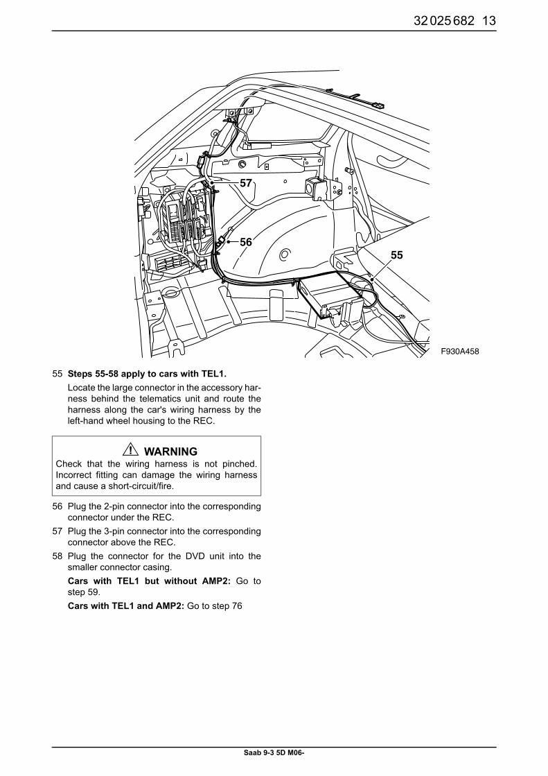
55 Steps 55-58 apply to cars with TEL1.Locate the large connector in the accessory har-ness behind the telematics unit and route theharness along the car's wiring harness by theleft-hand wheel housing to the REC.
56 Plug the 2-pin connector into the correspondingconnector under the REC.
57 Plug the 3-pin connector into the correspondingconnector above the REC.
58 Plug the connector for the DVD unit into thesmaller connector casing.Cars with TEL1 but without AMP2: Go tostep 59.Cars with TEL1 and AMP2: Go to step 76
WARNINGCheck that the wiring harness is not pinched.Incorrect fitting can damage the wiring harnessand cause a short-circuit/fire.
F930A458
55
57
56

14 32 025 682
Saab 9-3 5D M06-
59 Steps 59-75 apply to cars with TEL1 but without rear amplifier (AMP2).Locate the loose fibre optic cables by the spacefor the rear amplifier.
60 Remove the protective covers from the fibreoptic cables' connection.
61 Fit the green marked fibre optic cable in position1 in a fibre optic connector from the kit.
62 Fit the blue marked fibre optic cable in position2 in the same connector.
63 Fit the locking clip.64 Remove the protective cover from the long extra
fibre optic cable's connection and fit it in position1 in a fibre optic connector from the kit.
65 Remove the protective cover from the mediumlength extra fibre optic cable's connection and fitit in position 2 in the same connector.
66 Fit the locking clip. Plug the connectors intoeach other. Lock with the lock tab.
67 Route the fibre optic cables along the normalwiring harness so that the medium length fibreoptic cable reaches the DVD unit and the longone to the telematics unit.
68 Remove the protective cover from the mediumlength extra fibre optic cable's connection and fitit in position 2 in a fibre optic connector from thekit.
69 Remove the protective cover from the shortextra fibre optic cable's connection and fit it inposition 1 in the same connector.
70 Fit the locking clip.71 Plug the fibre optic connector into the DVD unit's
connector casing and plug it into the DVD unit.72 Remove the protective cover from the short
extra fibre optic cable's connection and fit it inposition 2 in a fibre optic connector from the kit.
73 Remove the protective cover from the long extrafibre optic cable's connection and fit it in position1 in the same connector.
74 Plug the fibre optic connector together with thewiring harness connector for the telematics unitinto the kit's large connector casing.
75 Plug the connector into the telematics unit.Go to step 131.
ImportantHandle the fibre-optic cables with care or the sig-nal may be distorted.
� It is very important that the two leads in theconnector are not confused with one another.
� Do not bend the cable in a radius smaller than25 mm.
� Keep the cable ends free from dirt and grime.
� The cable should not lie against any sharpedges as this may cause increased signalreduction.
F930A459
6561 62
63
60
74
66
61

32 025 682 15
Saab 9-3 5D M06-
76 Steps 76-98 apply to cars with TEL1 and rearamplifier (AMP2).Remove the connector from the rear amplifier.
77 Unplug the fibre optic cables' connector (thesmall connector) from the amplifier's connector.
78 Remove the fibre optic cable connected to posi-tion 1 by opening the connector locking clip andcarefully lifting the catch.
79 Fit the fibre optic cable in position 1 in a fibreoptic connector from the kit.
80 Fit the locking clip.81 Remove the protective cover from the connec-
tion on the longer extra fibre optic cable.
82 Fit the fibre optic cable in position 1 in a fibreoptic connector from the kit. Mark the other endwith tape.
83 Fit the locking clip.84 Plug the connectors into each other. Lock with
the lock tab.85 Remove the protective cover from the connec-
tion on the medium length extra fibre opticcable.
86 Fit the fibre optic cable in position 1 in the fibreoptic connector for AMP2.
87 Fit the locking clip.88 Plug the fibre optic connector into the connector
for the amplifier and plug it into the amplifier.
ImportantHandle the fibre-optic cables with care or the sig-nal may be distorted.
� Do not bend the cable in a radius smaller than25 mm.
� Do not expose the cable to impact as this maycause the transparent plastic to whiten,thereby reducing the intensity of the light andcausing possible communication interruptions.
� The cable should not lie against any sharpedges as this may cause increased signalreduction.
F930A460
77 78
81
78
88

16 32 025 682
Saab 9-3 5D M06-
89 Route the fibre optic cables along the normalwiring harness so that the unmarked fibre opticcable reaches the DVD unit and the marked oneto the telematics unit.
90 Remove the protective cover from the unmarkedfibre optic cable's connection and fit it in position2 in a fibre optic connector from the kit.
91 Remove the protective cover from the shortextra fibre optic cable's connection and fit it inposition 1 in the same connector.
92 Fit the locking clip.93 Plug the fibre optic connector into the DVD unit's
connector casing and plug it into the DVD unit.94 Remove the protective cover from the short
extra fibre optic cable's connection and fit it inposition 2 in a fibre optic connector from the kit.
95 Remove the protective cover from the connec-tion for the fibre optic cable marked with tapeand fit it in position 1 in the same connector.
96 Plug the 2-pin fibre optic connector together withthe wiring harness connector for the telematicsunit into the kit's large connector casing.
97 Plug the connector into the telematics unit.98 Secure the fibre optic cables and wiring harness
using cable ties starting from the telematics unit.Any excess should be pulled into a hoop byAMP2.Go to step 132.Important
Handle the fibre-optic cables with care or the sig-nal may be distorted.
� It is very important that the two leads in theconnector are not confused with one another.
� Do not bend the cable in a radius smaller than25 mm.
� Keep the cable ends free from dirt and grime.
� The cable should not lie against any sharpedges as this may cause increased signalreduction.
F930A461
9491 90
92
90,91
96
95
91

32 025 682 17
Saab 9-3 5D M06-
99 Steps 99-113 apply to cars with integratedphone but without rear amplifier (AMP2).Locate the loose fibre optic cable by the rearamplifier.
100Remove the protective cover from the fibre opticcable's connection.
101Fit the fibre optic cable in position 1 in a fibreoptic connector from the kit.
102Fit the locking clip.
103Remove the protective cover from the long extrafibre optic cable's connection and fit it in position1 in a fibre optic connector from the kit.
104Fit the locking clip. Plug the connectors intoeach other. Lock with the lock tab.
105Route the fibre optic cable along the normal wir-ing harness to the DVD unit.
106Remove the protective cover from the fibre opticcable's connection and fit it in position 2 in afibre optic connector from the kit.
107Remove the protective covers from the shortextra fibre optic cable's connections and fit oneend in position 1 in the same fibre opticconnector.
108Fit the locking clip.109Plug the fibre optic connector into the DVD unit's
connector casing and plug it into the DVD unit.110Unplug the fibre optic connector (the small con-
nector) from the telematics unit's connector.111 Remove the fibre optic cable connected to posi-
tion 2 by opening the connector locking clip andcarefully lifting the catch. Fit a protective coveron the loose end.
112Fit the fibre optic cable from the DVD unit inposition 2. Fit the locking clip.
113Plug the fibre optic connector into the large con-nector and plug it into the telematics unit.Go to step 131.
ImportantHandle the fibre-optic cables with care or the sig-nal may be distorted.
� Do not bend the cable in a radius smaller than25 mm.
� Do not expose the cable to impact as this maycause the transparent plastic to whiten,thereby reducing the intensity of the light andcausing possible communication interruptions.
� The cable should not lie against any sharpedges as this may cause increased signalreduction.
F930A462
107
108
109
106
110101
101

18 32 025 682
Saab 9-3 5D M06-
114Steps 114-136 apply to cars with integratedphone and rear amplifier (AMP2).Remove the connector from the rear amplifier.
115Unplug the fibre optic cables' connector (thesmall connector) from the amplifier's connector.
116Remove the fibre optic cable connected to posi-tion 1 by opening the connector locking clip andcarefully lifting the catch.
117Remove the protective cover from the connec-tion on the long extra fibre optic cable. Fit it onthe removed fibre optic cable.
118Fit the fibre optic cable in position 1 in the fibreoptic connector for AMP2.
119Fit the locking clip.120Plug the fibre optic connector into the large con-
nector and plug it into the amplifier.
ImportantHandle the fibre-optic cables with care or the sig-nal may be distorted.
� Do not bend the cable in a radius smaller than25 mm.
� Do not expose the cable to impact as this maycause the transparent plastic to whiten,thereby reducing the intensity of the light andcausing possible communication interruptions.
� The cable should not lie against any sharpedges as this may cause increased signalreduction.
F930A463
117
116115
116

32 025 682 19
Saab 9-3 5D M06-
121Route the fibre optic cable along the normal wir-ing harness to the DVD unit
122Remove the protective cover from the fibre opticcable's connection and fit it in position 2 in afibre optic connector from the kit.
123Remove the protective cover from the shortextra fibre optic cable's connection and fit it inposition 1 in the same connector.
124Fit the locking clip.125Plug the fibre optic connector into the DVD unit's
connector casing and plug it into the DVD unit.126Unplug the fibre optic cables' connector (the
small connector) from the telematics unit'sconnector.
127Remove the fibre optic cable connected to posi-tion 2 by opening the connector locking clip andcarefully lifting the hook.
128Remove the protective cover on the fibre opticcable from the DVD unit and fit it in position 2 ina fibre optic connector from the kit. Fit the pro-tective cover on the loose fibre optic cable.
129Fit the locking clip.130Plug the fibre optic connector into the large con-
nector and plug it into the telematics unit.ImportantHandle the fibre-optic cables with care or the sig-nal may be distorted.
� It is very important that the two leads in theconnector are not confused with one another.
� Do not bend the cable in a radius smaller than25 mm.
� Keep the cable ends free from dirt and grime.
� The cable should not lie against any sharpedges as this may cause increased signalreduction.
F930A464
128
129
130126
123
123
127

20 32 025 682
Saab 9-3 5D M06-
131Secure the fibre optic cables and wiring harnessusing cable ties starting from the telematics unit.Any excess should be pulled into a hoop byAMP2.
132Steps 132-135 must be carried out on bothsides.Fit the foam blocks
133Fit the rear side trims and the covers over thestorage compartments.
134Fit the side bolsters. Check that the seatbelt isnot twisted.
135Fit the C-pillar trim.136Fit the cargo guard (if the car was equipped with
one).137Fit the luggage compartment floor and scuff
plate.138Connect the diagnostic tool, select car and
model year, select “All”, select “Add/Remove”,select the current replaced/new fitted units(ICM, EHU, PU, DVD) and select “Add”.
139Place the map disc in the DVD player, check thesystem by test driving the car until the naviga-tion system makes contact with the satellites.The map should display on the screen.
NoteThe diagnostic tool will on some occasions needto retrieve a security code in TIS. Information onwhat to do will be displayed on the diagnostic tooldisplay.
F930A465
135
137
132137132
136
134
133
133