sa1 torsion - ch 4a - vtctycnw01.vtc.edu.hk/cbe2027/sa1_torsion.pdf · 2009-09-21 · when a steel...
TRANSCRIPT

CBE2027 Structural Analysis I Chapter 4 – Torsion
HD in Civil Engineering Page 4-1
TORSION
Torsional stress results from the action of torsional or twisting moments
acting about the longitudinal axis of a shaft. The effect of the application of
a torsional moment, combined with appropriate fixity at the supports, is to
cause torsional stresses within the shaft. These stresses, which are
effectively shear stresses, are greatest on the outer surface of the shaft.

CBE2027 Structural Analysis I Chapter 4 – Torsion
HD in Civil Engineering Page 4-2
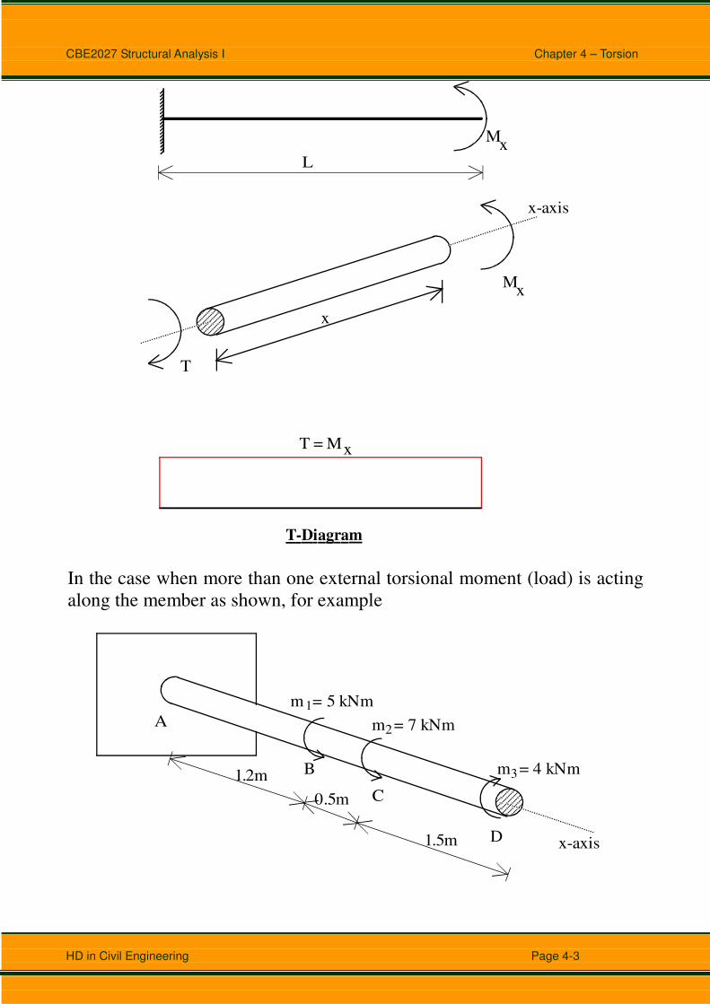
Internal Resisting Torsional Moment (T)
When a steel shaft (a circular section straight bar) with one end fixed and the
other end free is subject to a concentrated moment Mx at the free end. This
Mx is rotating about the longitudinal axis, x-axis of the shaft.
x-axis
Mx
x
The action of this moment Mx which is sometime called torque, will then
cause a twist (torsional rotation) of the shaft. The internal torsional
moment in the member under torsional load can be found by using the
equation of equilibrium.
∑ Mx = 0, ⇒ T = Mx
x
T
Mx
x-axis
It is seen in this example that the internal torsional moment T in all
cross-sections of this member remains constant.
CBE2027 Structural Analysis I Chapter 4 – Torsion
HD in Civil Engineering Page 4-3
x
T
Mx
x-axis
Mx
T-Diagram
L
T = Mx
In the case when more than one external torsional moment (load) is acting
along the member as shown, for example
x-axis 1.5m
0.5m
1.2m
A
B
C
D
m = 5 kNm
m = 7 kNm
m = 4 kNm
1
2
3
CBE2027 Structural Analysis I Chapter 4 – Torsion
HD in Civil Engineering Page 4-4
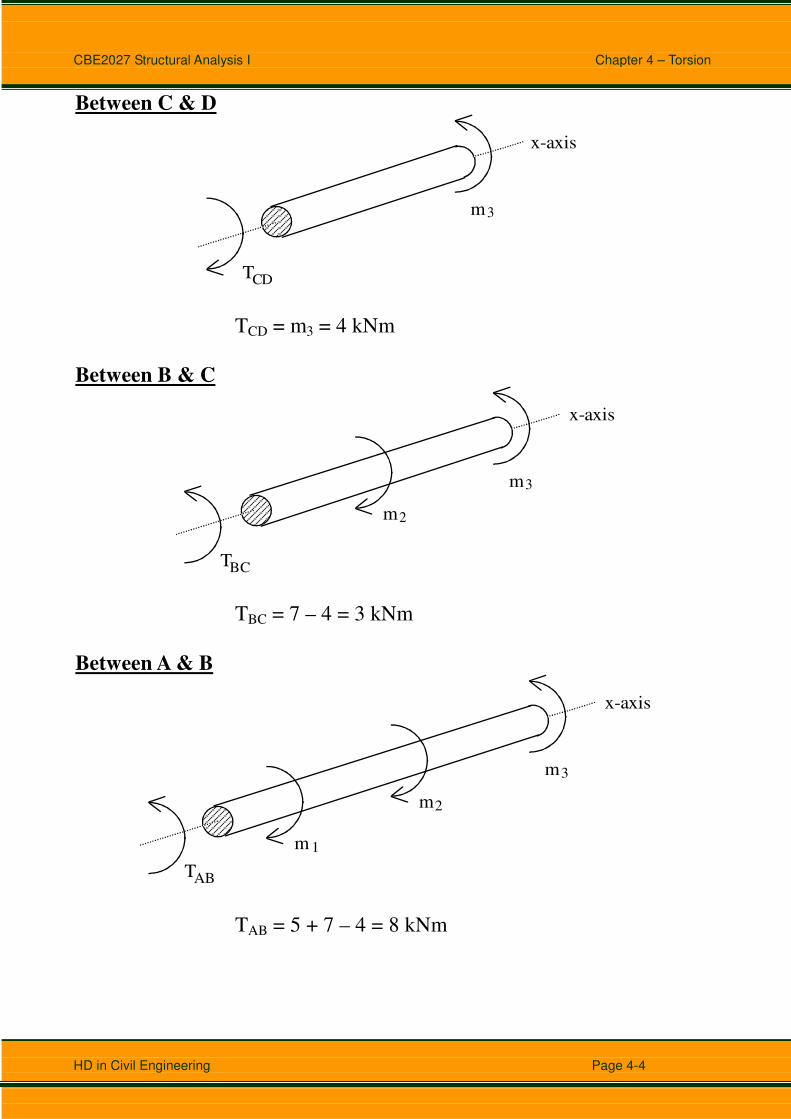
Between C & D
T
x-axis
m 3
CD
TCD = m3 = 4 kNm
Between B & C
T
x-axis
m 3
BC
m 2
TBC = 7 – 4 = 3 kNm
Between A & B
T
x-axis
m 3
AB
m 2
m 1
TAB = 5 + 7 – 4 = 8 kNm

CBE2027 Structural Analysis I Chapter 4 – Torsion
HD in Civil Engineering Page 4-5
A B C D
8 kNm
3 kNm
-4 kNm
CBE2027 Structural Analysis I Chapter 4 – Torsion
HD in Civil Engineering Page 4-6
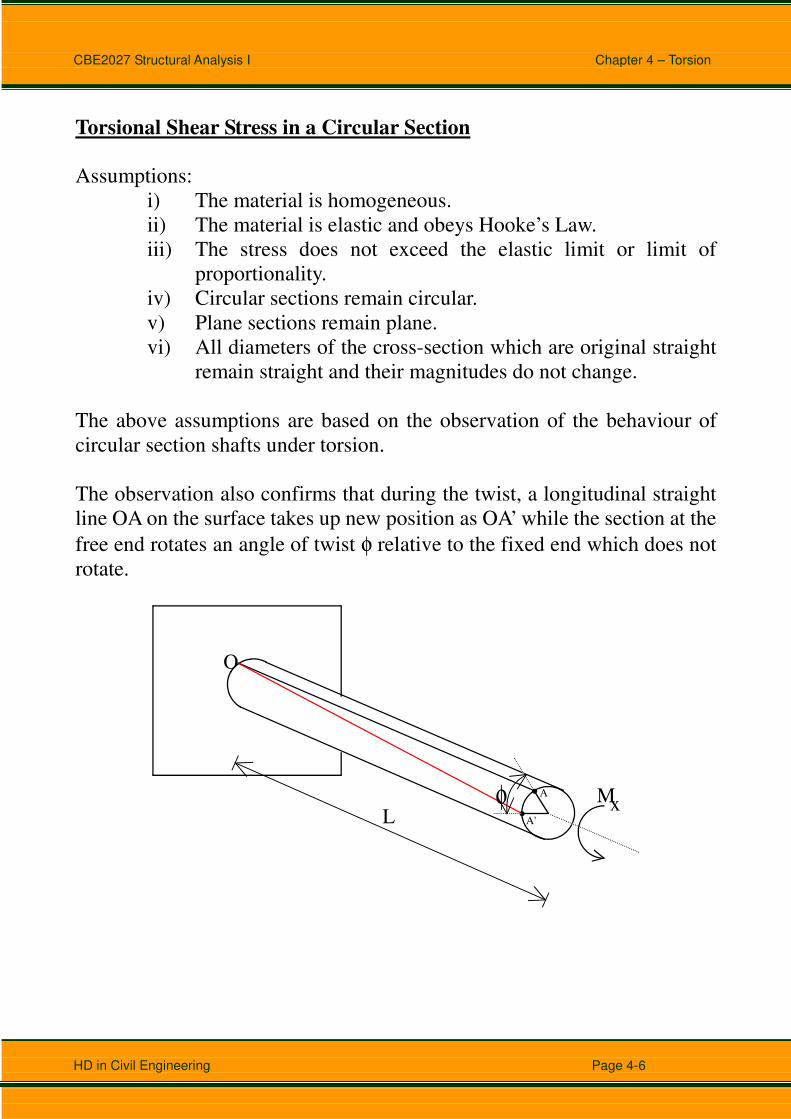
Torsional Shear Stress in a Circular Section
Assumptions:
i) The material is homogeneous.
ii) The material is elastic and obeys Hooke’s Law.
iii) The stress does not exceed the elastic limit or limit of
proportionality.
iv) Circular sections remain circular.
v) Plane sections remain plane.
vi) All diameters of the cross-section which are original straight
remain straight and their magnitudes do not change.
The above assumptions are based on the observation of the behaviour of
circular section shafts under torsion.
The observation also confirms that during the twist, a longitudinal straight
line OA on the surface takes up new position as OA’ while the section at the
free end rotates an angle of twist φ relative to the fixed end which does not
rotate.
L
A
A'
O
Mxφ
CBE2027 Structural Analysis I Chapter 4 – Torsion
HD in Civil Engineering Page 4-7
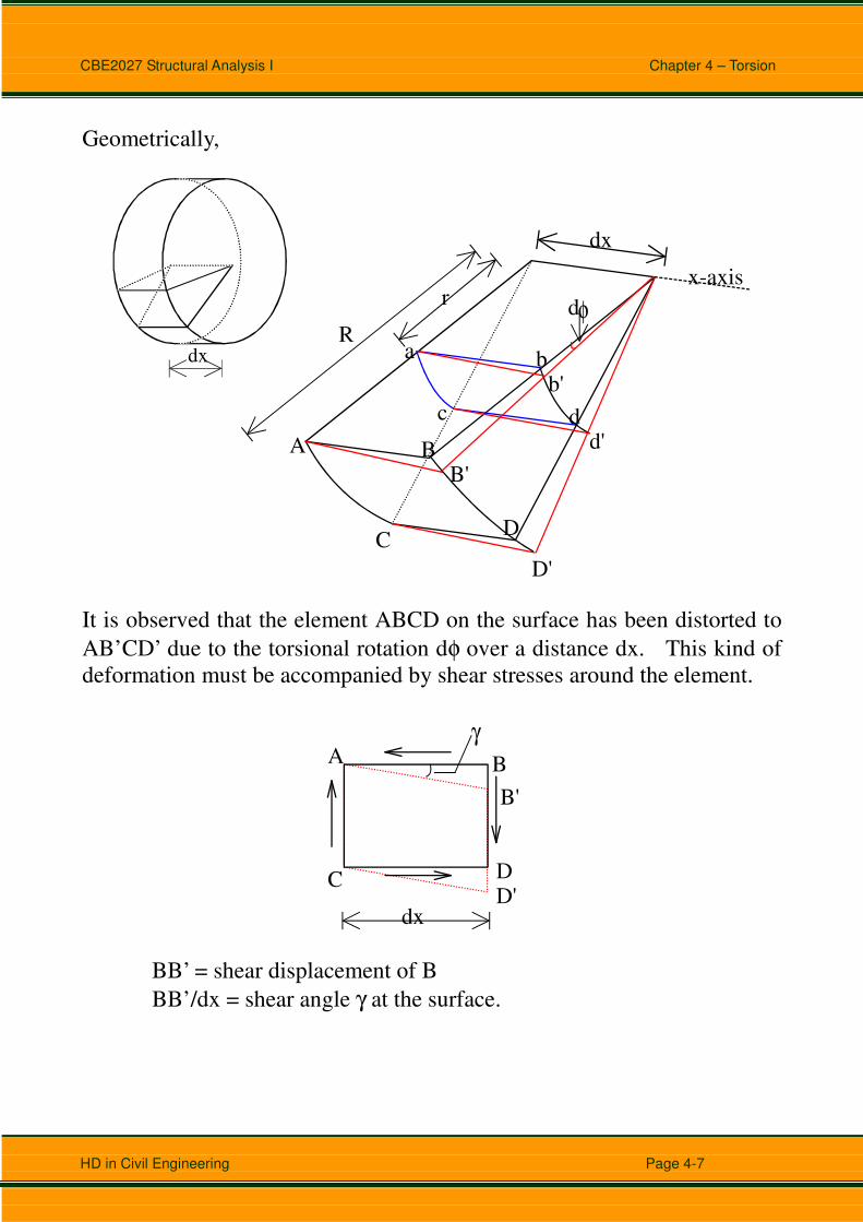
Geometrically,
R
rx-axis
A
C
B
D
B'
D'
a bb'
dd'
c
dφ
dx
dx
It is observed that the element ABCD on the surface has been distorted to
AB’CD’ due to the torsional rotation dφ over a distance dx. This kind of
deformation must be accompanied by shear stresses around the element.
A B
C DD'
B'
dx
γ
BB’ = shear displacement of B
BB’/dx = shear angle γ at the surface.

CBE2027 Structural Analysis I Chapter 4 – Torsion
HD in Civil Engineering Page 4-8
Somewhere between the centre (x-axis) & the surface, an element abcd also
has the similar deformation.
a b
c dd'
b'
dx
γr
γ r(dx)
bb’ = γr dx = shear displacement of b
γr = shear angle
On the other hand, bb’ = rdφ
dx
dr
r
φγ =
Physically, G
τγ =
Therefore, γτ G=
dx
dGr
r
φτ =
In which dx
dφ is the torsional rotation of the shaft per unit length.
Equation of equilibrium,
r
dA τr
CBE2027 Structural Analysis I Chapter 4 – Torsion
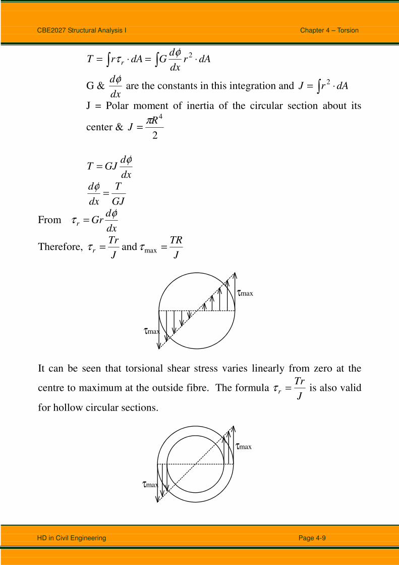
HD in Civil Engineering Page 4-9
∫∫ ⋅=⋅= dArdx
dGdArT
r
2φτ
G & dx
dφ are the constants in this integration and ∫ ⋅= dArJ
2
J = Polar moment of inertia of the circular section about its
center & 2
4R
Jπ
=
dx
dGJT
φ=
GJ
T
dx
d=
φ
From dx
dGr
r
φτ =
Therefore, J
TR
J
Trr
== max and ττ
τmax
τmax
It can be seen that torsional shear stress varies linearly from zero at the
centre to maximum at the outside fibre. The formula J
Trr
=τ is also valid
for hollow circular sections.
τmax
τmax

CBE2027 Structural Analysis I Chapter 4 – Torsion
HD in Civil Engineering Page 4-10
When a circular shaft is subjected to torsion, the elements between two
adjacent cross-sections are under pure shear.
τ
τ
τ
τ
τ
σ
σσ 12
From Mohr’s circle, it can be seen that the principal stresses, τσσ =−= 21 .
τ
τ
τ
τ
σ
σ σ
σ21
1 2
The occurrence of max1 τσ = at 45o to longitudinal axis causes cracking of
brittle shaft because brittle material is very weak in tension, like cast iron &
chalk.
mx
mx σσ1
1

CBE2027 Structural Analysis I Chapter 4 – Torsion
HD in Civil Engineering Page 4-11
If this shaft is made of mild steel which is ductile material strong in tension
& compression but is comparatively weak in shear. This shaft will
eventually fail in shear when the external torsional load keeps on increasing.
The failure section is the cross-section of the shaft perpendicular to its
longitudinal axis.
Ductile Material

CBE2027 Structural Analysis I Chapter 4 – Torsion
HD in Civil Engineering Page 4-12
Torsional Rotation
L
A
A'
O
Mxφ
The deformation of a shaft under pure torsion is the torsional rotation φ of a
cross-section.
From GJ
T
dx
d=
φ
∫=
=L
xGJ
TL
GJ
Tdx
0
= thereforeφφ
The φ is then the torsional rotation of the free end as the fixed end does not
rotate.

CBE2027 Structural Analysis I Chapter 4 – Torsion
HD in Civil Engineering Page 4-13
Summary of Formulae for Torsion of Circular Section
Maximum Shear Stress:
J
TR=maxτ
Shear Stress at any radial position r:
J
Trr
=τ
Polar Moment of Inertia for Solid Circular Section:
232
44RD
Jππ
==
D
Polar Moment of Inertia for Hollow Circular Section:
( ) ( )
232
4444ioio
RRDDJ
−=
−=
ππ
Do
iD
Angle of Twist for Circular Section:
GJ
TL=φ
CBE2027 Structural Analysis I Chapter 4 – Torsion
HD in Civil Engineering Page 4-14
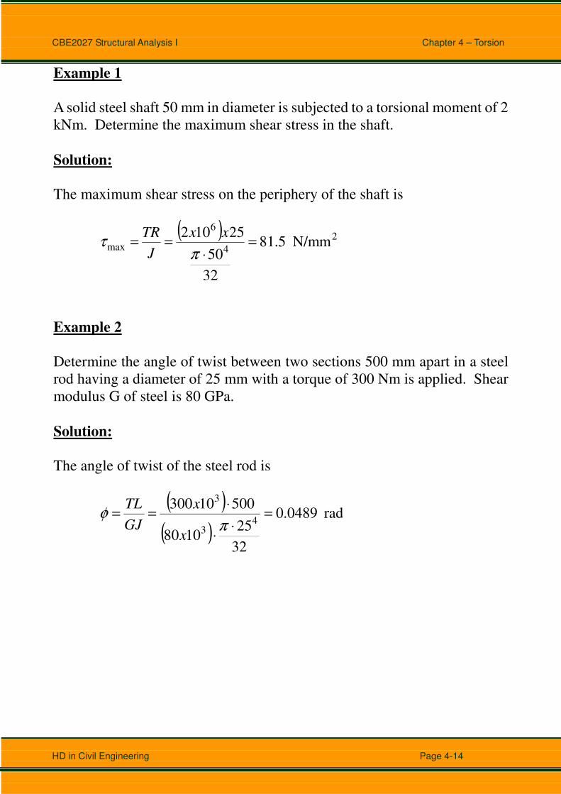
Example 1
A solid steel shaft 50 mm in diameter is subjected to a torsional moment of 2
kNm. Determine the maximum shear stress in the shaft.
Solution:
The maximum shear stress on the periphery of the shaft is
( ) 2
4
6
max N/mm 5.81
32
50
25102=
⋅==
πτ
xx
J
TR
Example 2
Determine the angle of twist between two sections 500 mm apart in a steel
rod having a diameter of 25 mm with a torque of 300 Nm is applied. Shear
modulus G of steel is 80 GPa.
Solution:
The angle of twist of the steel rod is
( )
( )rad 0489.0
32
251080
500103004
3
3
=⋅
⋅
⋅==
πφ
x
x
GJ
TL
CBE2027 Structural Analysis I Chapter 4 – Torsion
HD in Civil Engineering Page 4-15
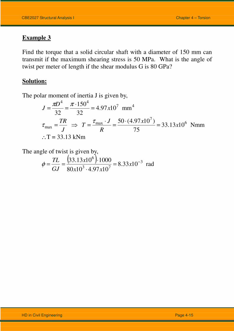
Example 3
Find the torque that a solid circular shaft with a diameter of 150 mm can
transmit if the maximum shearing stress is 50 MPa. What is the angle of
twist per meter of length if the shear modulus G is 80 GPa?
Solution:
The polar moment of inertia J is given by,
4744
mm 1097.432
150
32x
DJ =
⋅==
ππ
Nmm 1013.3375
)1097.4(50 6
7max
max xx
R
JT
J
TR=
⋅=
⋅=⇒=
ττ
∴T = 33.13 kNm
The angle of twist is given by,
( )
rad 1033.81097.41080
10001013.33 3
73
6−=
⋅
⋅== x
xx
x
GJ
TLφ
CBE2027 Structural Analysis I Chapter 4 – Torsion
HD in Civil Engineering Page 4-16
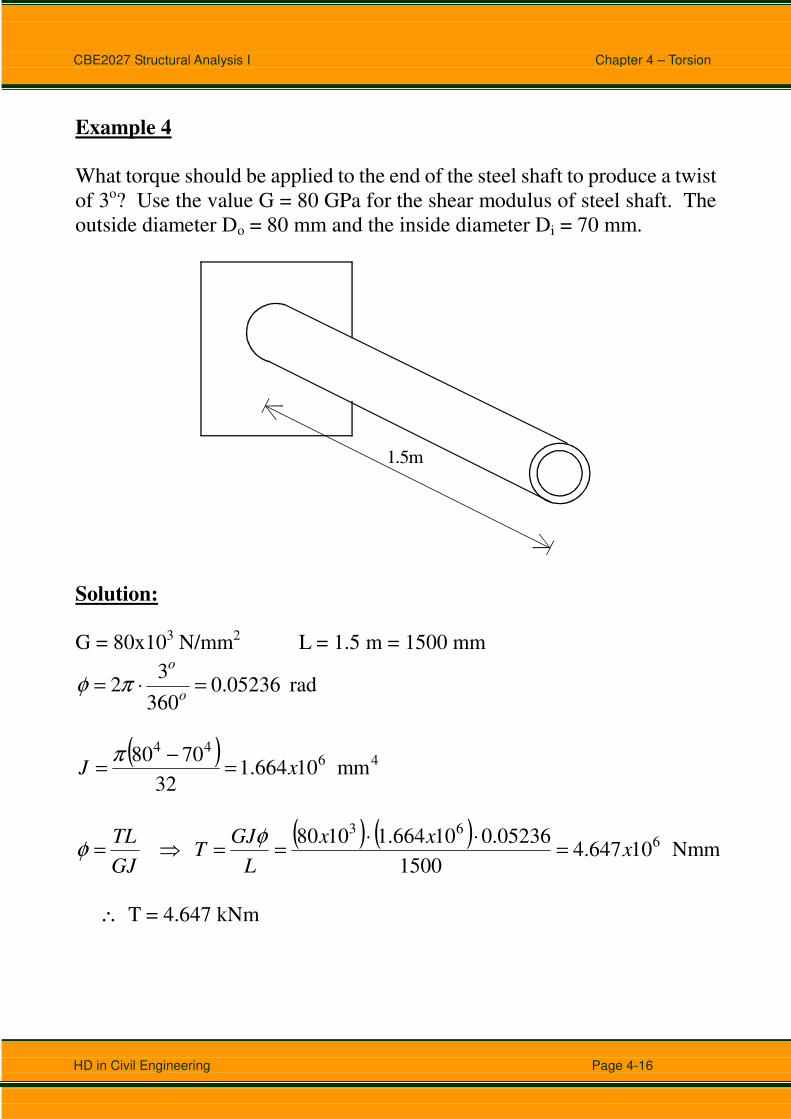
Example 4
What torque should be applied to the end of the steel shaft to produce a twist
of 3o? Use the value G = 80 GPa for the shear modulus of steel shaft. The
outside diameter Do = 80 mm and the inside diameter Di = 70 mm.
1.5m
Solution:
G = 80x103 N/mm2 L = 1.5 m = 1500 mm
rad 05236.0360
32 =⋅=
o
o
πφ
( ) 4644
mm 10664.132
7080xJ =
−=
π
( ) ( )Nmm 10647.4
1500
05236.010664.11080 6
63
xxx
L
GJT
GJ
TL=
⋅⋅==⇒=
φφ
∴ T = 4.647 kNm

CBE2027 Structural Analysis I Chapter 4 – Torsion
HD in Civil Engineering Page 4-17
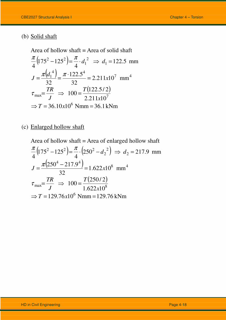
Example 5
The preliminary design of a large shaft connecting a motor to a generator
calls for the use of a hollow shaft with inner and outer diameters of 125 mm
and 175 mm respectively. Knowing that the allowable shearing stress is 100
MPa, determine the maximum torque which may be transmitted (a) by the
shaft as designed, (b) by a solid shaft of the same weight, (c) by a hollow
shaft of the same weight and 250 mm outside diameter.
Solution:
(a)
(b)
(c)
125
175
d1
d2
250
(a) Hollow shaft as Designed
( ) 47
44
mm 10811.632
125175xJ =
−=
π
( )
10811.6
2/175100
7maxx
T
J
TR=⇒=τ
kNm 77.84 Nmm 1084.77 6 ==⇒ xT
CBE2027 Structural Analysis I Chapter 4 – Torsion
HD in Civil Engineering Page 4-18
(b) Solid shaft
Area of hollow shaft = Area of solid shaft
( ) mm 5.122 4
1251754
12
122 =⇒⋅=− dd
ππ
( ) 4744
1 mm 10211.232
5.122
32x
dJ =
⋅==
ππ
( )
10211.2
2/5.122100
7maxx
T
J
TR=⇒=τ
kNm 36.1 Nmm 1010.36 6 ==⇒ xT
(c) Enlarged hollow shaft
Area of hollow shaft = Area of enlarged hollow shaft
( ) ( ) mm 9.217 2504
1251754
22
2222 =⇒−⋅=− dd
ππ
( ) 4844
mm 10622.132
9.217250xJ =
−=
π
( )
10622.1
2/250100
8maxx
T
J
TR=⇒=τ
kNm 129.76 Nmm 1076.129 6 ==⇒ xT
CBE2027 Structural Analysis I Chapter 4 – Torsion
HD in Civil Engineering Page 4-19
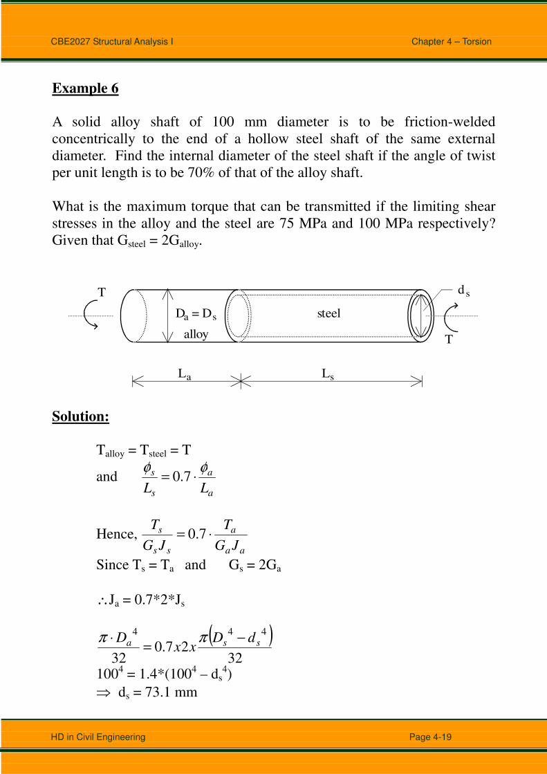
Example 6
A solid alloy shaft of 100 mm diameter is to be friction-welded
concentrically to the end of a hollow steel shaft of the same external
diameter. Find the internal diameter of the steel shaft if the angle of twist
per unit length is to be 70% of that of the alloy shaft.
What is the maximum torque that can be transmitted if the limiting shear
stresses in the alloy and the steel are 75 MPa and 100 MPa respectively?
Given that Gsteel = 2Galloy.
L La s
D = Da
d s
s
T
T
steel
alloy
Solution:
Talloy = Tsteel = T
and a
a
s
s
LL
φφ⋅= 7.0
Hence, aa
a
ss
s
JG
T
JG
T⋅= 7.0
Since Ts = Ta and Gs = 2Ga
∴Ja = 0.7*2*Js
( )32
27.032
444ssa
dDxx
D −=
⋅ ππ
1004 = 1.4*(1004 – ds4)
⇒ ds = 73.1 mm
CBE2027 Structural Analysis I Chapter 4 – Torsion
HD in Civil Engineering Page 4-20
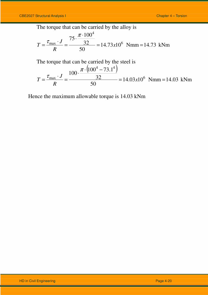
The torque that can be carried by the alloy is
kNm 14.73 Nmm 1073.1450
32
10075
6
4
max ==
⋅⋅
=⋅
= xR
JT
πτ
The torque that can be carried by the steel is
( )kNm 14.03 Nmm 1003.14
50
32
1.73100100
6
44
max ==
−⋅⋅
=⋅
= xR
JT
πτ
Hence the maximum allowable torque is 14.03 kNm
CBE2027 Structural Analysis I Chapter 4 – Torsion
HD in Civil Engineering Page 4-21
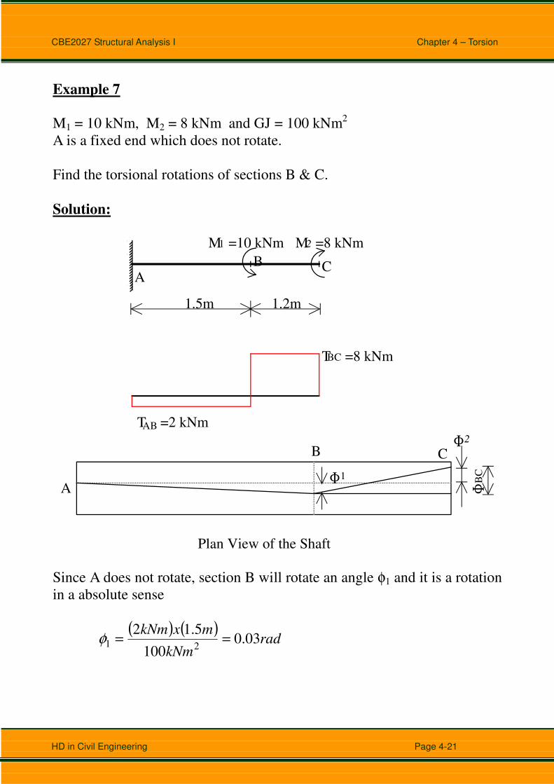
Example 7
M1 = 10 kNm, M2 = 8 kNm and GJ = 100 kNm2
A is a fixed end which does not rotate.
Find the torsional rotations of sections B & C.
Solution:
AB C
M =10 kNm M =8 kNm1 2
1.5m 1.2m
T =8 kNm
T =2 kNmAB
BC
A
B C
Plan View of the Shaft
ΦΦ
1 BC
Φ2
Since A does not rotate, section B will rotate an angle φ1 and it is a rotation
in a absolute sense
( ) ( )
radkNm
mxkNm03.0
100
5.1221 ==φ

CBE2027 Structural Analysis I Chapter 4 – Torsion
HD in Civil Engineering Page 4-22
If section B did not rotate, then section C rotates relative to B an angle of
( ) ( )
radx
BC096.0
100
2.18==φ
Since section B does not rotate, therefore section C rotates, relative to A, an
angle of
φ2 = φ1 - φBC = 0.03 – 0.096 = -0.066 rad.
CBE2027 Structural Analysis I Chapter 4 – Torsion
HD in Civil Engineering Page 4-23
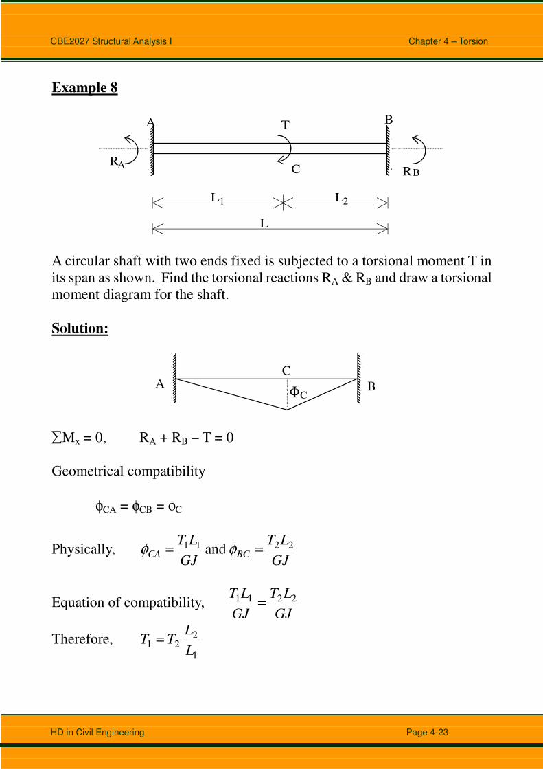
Example 8
A B
RR
L
AB
1 2L L
C
T
A circular shaft with two ends fixed is subjected to a torsional moment T in
its span as shown. Find the torsional reactions RA & RB and draw a torsional
moment diagram for the shaft.
Solution:
AC
B CΦ
∑Mx = 0, RA + RB – T = 0
Geometrical compatibility
φCA = φCB = φC
Physically, GJ
LT
GJ
LTBCCA
2211 and == φφ
Equation of compatibility, GJ
LT
GJ
LT 2211 =
Therefore, 1
221
L
LTT =
CBE2027 Structural Analysis I Chapter 4 – Torsion
HD in Civil Engineering Page 4-24
Note that L1 + L2 = L, RA = T1 and RB = T2
TTL
LT =+∴ 2
1
22
TL
LT =
+⇒
1
22 1
TL
LT =
⇒
12
TL
LTR
B⋅== 1
2
TL
LTR
A⋅== 2
1
A C
B
T
T
1
2

CBE2027 Structural Analysis I Chapter 4 – Torsion
HD in Civil Engineering Page 4-25
Tutorial 4 (Torsion)
Q1. (a) Determine the torque T which causes an angle of twist of 3o in
the hollow cylindrical steel shaft as shown below (G = 77 GPa).
(b) Determine the angle of twist caused by the same torque T in a
solid cylindrical shaft of the same cross-sectional area.
45mm30 mm
2.4
m
T
Q2. A solid steel shaft is loaded as shown below. Using G = 83 GPa,
determine the required diameter of the shaft if the shearing stress is
limited to 60 MPa and the angle of rotation at the free end is not to
exceed 4o.
2.5 m 2.5 m
750 Nm 1200 Nm
CBE2027 Structural Analysis I Chapter 4 – Torsion
HD in Civil Engineering Page 4-26
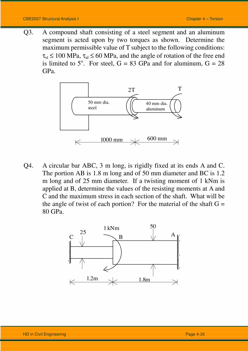
Q3. A compound shaft consisting of a steel segment and an aluminum
segment is acted upon by two torques as shown. Determine the
maximum permissible value of T subject to the following conditions:
τst ≤ 100 MPa, τal ≤ 60 MPa, and the angle of rotation of the free end
is limited to 5o. For steel, G = 83 GPa and for aluminum, G = 28
GPa.
50 mm dia.
steel40 mm dia.
aluminum
1000 mm 600 mm
T 2T
Q4. A circular bar ABC, 3 m long, is rigidly fixed at its ends A and C.
The portion AB is 1.8 m long and of 50 mm diameter and BC is 1.2
m long and of 25 mm diameter. If a twisting moment of 1 kNm is
applied at B, determine the values of the resisting moments at A and
C and the maximum stress in each section of the shaft. What will be
the angle of twist of each portion? For the material of the shaft G =
80 GPa.
ABC
1.2m 1.8m
25501 kNm

CBE2027 Structural Analysis I Chapter 4 – Torsion
HD in Civil Engineering Page 4-27
Q5. The solid cylinders AB and BC are bonded together at B and
attached to fixed supports at A and C. Knowing that AB is made of
aluminum (G = 26 GPa) and BC of brass (G = 39 GPa), determine for
the loading (acted at B) shown:
(a) the reaction at each support;
(b) the maximum shearing stress in AB;
(c) the maximum shearing stress in BC.
125 mm
75 mm
300 mm 200 mm
12.5 kNm
A
B
C