s6l1d-e4 wdg.311/312 - technical data sheetstandards quality assurance excitation and voltage...
TRANSCRIPT
Standards
Quality Assurance
Excitation and Voltage Regulators
AVR Type MX341 MX321 DECS100
Voltage Regulation ± 1% ± 0.5% ± 0.25%
AVR Power PMG PMG PMG
S6L1D-E4 Wdg.311/312 - Technical Data Sheet
STAMFORD industrial alternators meet the requirements of the relevant parts of the IEC EN 60034 and the relevant
section of other international standards such as BS5000, VDE 0530, NEMA MG1-32, IEC34, CSA C22.2-100 and
AS1359. Other standards and certifications can be considered on request.
Excitation System
Alternators are manufactured using production procedures having a quality assurance level to BS EN ISO 9001.
with 4% Engine Governing
No Load Excitation Voltage (V) 13.5 - 13.6
No Load Excitation Current (A) 0.69 - 0.68
Full Load Excitation Voltage (V) 62
Full Load Excitation Current (A) 2.8
Exciter Time Constant (seconds) 0.16
Page 1 S6L1D-E4_Wdg.311/312_A059B537_Rev.A_24.01.2018

50 Hz 60 Hz
THF<2% TIF<50
1.41 m³/sec 1.69 m³/sec
380 400 415 440 416 440 460 480
190 200 208 220 208 220 230 240
220 230 240 254 240 254 266 277
1000 1050 1050 1010 1150 1200 1250 1300
Saturated Values in Per Unit at Base Ratings and Voltages
2.79 2.64 2.45 2.10 3.21 2.99 2.85 2.72
0.18 0.17 0.16 0.13 0.20 0.19 0.18 0.17
0.14 0.14 0.13 0.11 0.16 0.15 0.15 0.14
2.17 2.05 1.91 1.63 2.50 2.33 2.22 2.12
0.34 0.32 0.30 0.25 0.39 0.36 0.34 0.33
0.08 0.07 0.07 0.06 0.09 0.08 0.08 0.08
0.20 0.19 0.18 0.15 0.23 0.21 0.20 0.20
0.08 0.07 0.07 0.06 0.09 0.08 0.08 0.08
Unsaturated Values in Per Unit at Base Ratings and Voltages
3.34 3.17 2.94 2.52 3.85 3.59 3.42 3.27
0.20 0.19 0.18 0.15 0.23 0.22 0.21 0.20
0.17 0.16 0.15 0.13 0.19 0.18 0.17 0.16
2.23 2.12 1.97 1.68 2.57 2.40 2.29 2.18
0.40 0.38 0.35 0.30 0.46 0.43 0.41 0.39
0.09 0.08 0.08 0.07 0.10 0.09 0.09 0.09
0.10 0.09 0.09 0.07 0.11 0.11 0.10 0.10
0.24 0.23 0.21 0.18 0.28 0.26 0.24 0.23
0.09 0.09 0.08 0.07 0.10 0.10 0.09 0.09
* Parallel Star connection only available with Wdg 311
S6L1D-E4 Wdg.311/312
Electrical Data
Insulation System H
Stator Winding Double Layer Concentric
Winding Pitch 2/3
Winding Leads 12/6
Winding Number 311/312
NO LOAD < 1.5% NON-DISTORTING BALANCED LINEAR LOAD < 5.0%
Short Circuit Ratio 1/Xd
Steady State X/R Ratio 22.07
4
IP Rating IP23
RFI Suppression BS EN 61000-6-2 & BS EN 61000-6-4,VDE 0875G, VDE 0875N.
Refer to factory for others
Cooling Air Flow
Voltage Series Star (V)
kVA Base Rating (Class H) for
Reactance Values (kVA)
Telephone Interference
Number of Poles
Waveform Distortion
Xq Quad. Axis Reactance
Xd Dir. Axis Synchronous
X'd Dir. Axis Transient
X''d Dir. Axis Subtransient
Voltage Parallel Star (V) *
Voltage Delta (V)
Xd Dir. Axis Synchronous
X''q Quad. Axis Subtransient
XL Stator Leakage Reactance
X2 Negative Sequence Reactance
X0 Zero Sequence Reactance
X'd Dir. Axis Transient
X''d Dir. Axis Subtransient
Xq Quad. Axis Reactance
X''q Quad. Axis Subtransient
XL Stator Leakage Reactance
Xlr Rotor Leakage Reactance
X2 Negative Sequence Reactance
X0 Zero Sequence Reactance
Page 2 S6L1D-E4_Wdg.311/312_A059B537_Rev.A_24.01.2018

400V 480V
SG1.0 0.29 0.289
SG1.2 1.181 1.063
S6L1D-E4 Wdg.311/312
Time Constants (Seconds)
T’d Transient Time Const. 0.101
T’’d Sub-Transient Time Const. 0.0161
Exciter Stator Winding Resistance 19.56
T’do O.C. Field Time Const. 3.57
Ta Armature Time Const. 0.0236
T’’q Sub-Transient Time Const. 0.0104
Resistances in Ohms (Ω) at 220C
Stator Winding Resistance (Ra), per
phase for series connected 0.0022
Rotor Winding Resistance (Rf) 1.91
Exciter Rotor Winding Resistance per
phase 0.1
PMG Phase Resistance (Rpmg) per
phase1.91
Positive Sequence Resistance (R1) 0.0028
Shaft and Keys
All alternator rotors are dynamically balanced to better than BS6861: Part 1 Grade 2.5 for
minimum vibration in operation. Two bearing generators are balanced with a half key.
Negative Sequence Resistance (R2) 0.0032
Zero Sequence Resistance (R0) 0.0028
Saturation Factors
Mechanical Data
1 Bearing 2 Bearing
SAE Adaptor SAE0,1 SAE0,1
Moment of Inertia 20.014 kgm² 19.49 kgm²
Weight Wound Stator 999kg 999kg
Shipping weight in a Crate 2063kg 2145kg
Weight Complete Alternator 2020kg 2102kg
Weight Wound Rotor 853kg 811kg
Packing Crate Size 170x90x153(cm) 170x90x153(cm)
Maximum Over Speed 2250 RPM for two minutes
Bearing Drive End - BALL 6224
Bearing Non-Drive End BALL 6317 BALL 6317
Page 3 S6L1D-E4_Wdg.311/312_A059B537_Rev.A_24.01.2018

50Hz 60Hz
THREE PHASE EFFICIENCY CURVES
S6L1D-E4 Wdg.311/312
Page 4 S6L1D-E4_Wdg.311/312_A059B537_Rev.A_24.01.2018

Locked Rotor Motor Starting Curves - Separately Excited
Transient Voltage Dip Scaling Factor
Locked Rotor Motor Starting Curves - Self Excited
Transient Voltage Rise Scaling Factor
For voltage rise multiply voltage dip by 1.25
S6L1D-E4 Wdg.311/312
0.9 0.83
0.6 0.93
0.7 0.9
0.8 0.85
PF Factor
< 0.5 1
0.5 0.97
50Hz
60Hz
Page 5 S6L1D-E4_Wdg.311/312_A059B537_Rev.A_24.01.2018
50Hz 60Hz 3-phase 2-phase L-L 1-phase L-N
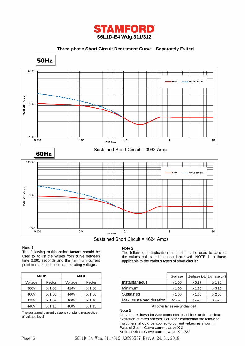
Voltage Factor Voltage Factor Instantaneous x 1.00 x 0.87 x 1.30
380V X 1.00 416V X 1.00 Minimum x 1.00 x 1.80 x 3.20
400V X 1.05 440V X 1.06 Sustained x 1.00 x 1.50 x 2.50
415V X 1.09 460V X 1.10 Max. sustained duration 10 sec. 5 sec. 2 sec.
440V X 1.16 480V X 1.15
The sustained current value is constant irrespective
of voltage level
All other times are unchanged
S6L1D-E4 Wdg.311/312
Three-phase Short Circuit Decrement Curve - Separately Exited
Sustained Short Circuit = 3963 Amps
Sustained Short Circuit = 4624 Amps
Note 1The following multiplication factors should beused to adjust the values from curve betweentime 0.001 seconds and the minimum currentpoint in respect of nominal operating voltage :
Note 2The following multiplication factor should be used to convertthe values calculated in accordance with NOTE 1 to thoseapplicable to the various types of short circuit :
Note 3Curves are drawn for Star connected machines under no-load excitation at rated speeds. For other connection the following multipliers should be applied to current values as shown : Parallel Star = Curve current value X 2Series Delta = Curve current value X 1.732
50Hz
60Hz
S6L1D-E4_Wdg.311/312_A059B537_Rev.A_24.01.2018Page 6

S6L1D-E4 Wdg.311/312
Typical Alternator Operating Charts
400V/50Hz
480V/60Hz
S6L1D-E4_Wdg.311/312_A059B537_Rev.A_24.01.2018Page 7

S6L1D-E4 Wdg.311/312
RATINGS AT 0.8 POWER FACTOR
Class - Temp Rise
Series Star (V) 380 400 415 440 380 400 415 440 380 400 415 440 380 400 415 440
kVA 1100 1125 1125 1100 1060 1100 1100 1060 1000 1050 1050 1010 900 945 945 900
kW 880 900 900 880 848 880 880 848 800 840 840 808 720 756 756 720
Efficiency (%) 94.8 94.9 95.0 95.2 94.9 95.0 95.1 95.3 95.1 95.1 95.2 95.4 95.3 95.3 95.4 95.5
kW Input 928 949 947 925 893 927 926 890 841 883 882 847 755 793 792 754
Series Star (V) 416 440 460 480 416 440 460 480 416 440 460 480 416 440 460 480
kVA 1250 1300 1350 1400 1206 1250 1300 1350 1150 1200 1250 1300 1063 1100 1150 1188
kW 1000 1040 1080 1120 965 1000 1040 1080 920 960 1000 1040 850 880 920 950
Efficiency (%) 95.0 95.1 95.1 95.1 95.1 95.2 95.2 95.2 95.2 95.3 95.3 95.3 95.3 95.4 95.4 95.5
kW Input 1053 1094 1136 1178 1015 1051 1093 1134 966 1008 1050 1091 892 922 964 996
De-Rates
All values tabulated above are subject to the following reductions:
- 5% when air inlet filters are fitted
- 3% for every 500 meters by which the operating altitude exceeds 1000 meters above mean sea level
- 3% for every 5°C by which the operational ambient temperature exceeds 40°C
- For any other operating conditions impacting the cooling circuit please refer to applications
Note: Requirement for operating in an ambient exceeding 60°C and altitude exceeding 4000 meters must be
referred to applications.
Dimensional and Torsional Drawing
For dimensional and torsional information please refer to the alternator General Arrangement and rotor drawings
available on our website (http://stamford-avk.com/)
Note: Continuous development of our products means that the information contained in our data sheets can
change without notice, and specifications should always be confirmed with Cummins Generator
Technologies prior to purchase.
Standby - 163/27°C Standby - 150/40°C Cont. H - 125/40°C Cont. F - 105/40°C
50Hz
60Hz
S6L1D-E4_Wdg.311/312_A059B537_Rev.A_24.01.2018Page 8