s4d-2 maunal · s4d-2 impotant notes ... do not install on asphalt or other similar unstable...
TRANSCRIPT


1
4,000KG
TWO-COLUMN AUTOMOTIVE LIFT
Model: S4D-2 MANUAL
2
Table of Contents WARRANTY ..................................................................................................................... 2
S4D-2 Definition ............................................................................................................... 3
S4D-2 Important Notes .................................................................................................... 3
S4D-2 BASIC SPECIFICATION ...................................................................................... 4
S4D-2 SET-UP DIMENSIONS ......................................................................................... 4
IMPORTANT FOUNDATION AND ANCHORING INFORMATION .................................. 5
ANCHORING TIP SHEET ............................................................................................... 6
PREPARATION ................................................................................................................ 6
GENERAL INFORMATION .............................................................................................. 7
RAISE LIFT .................................................................................................................... 11
LOWER LIFT ................................................................................................................. 11
SAFETY PROCEDURES .............................................................................................. 12
MAINTENANCE SCHEDULE ........................................................................................ 13
DAILY PRE-OPERATION CHECK(8 HOURS) .............................................................. 13
WEEKLY MAINTENANCE(40 HOURS) ........................................................................ 14
YEARLY MAINTENANCE .............................................................................................. 14
TROUBLESHOOTING ................................................................................................... 15
OWNER / EMPLOYER RESPONSIBILITIES ................................................................ 16
S4D-2 INSTALLATION / PARTS BREAKDOWN ........................................................... 17
S4D-2 PARTS LIST ....................................................................................................... 29
3
4,000KG CAPACITY MODEL: S4D-2
TWO-COLUMN AUTOMOTIVE LIFT READ THIS ENTIRE MANUAL BEFORE OPERATION BEGINS
RECORD BELOW THE FOLLOWING INFORMATION WHICH IS LOCATED ON THE
SERIAL NUMBER DATA PLATE Serial No.
Model No.
Date of Install

4
WARRANTY The structural components on your new automotive lift are warranted for five years on equipment. Operating components are warranted one year to the original purchaser, wiring are warranted six-months ,wearing parts only for purchasing,to be free of defects in material and workmanship.
The manufacturer shall repair or replace at their option for this period those parts returned to the factory freight prepaid which prove after inspection to be defective.
This warranty only applies to the original purchaser of the equipment. This warranty does not extend to defects caused by ordinary wear, abuse, misuse, shipping damage, or damage as the result of improper maintenance.
This warranty is exclusive and in lieu of all other warranties expressed or implied.
In no event shall the manufacturer be liable for special, consequential or incidental damages for breach or delay in performance of the warranty.
The manufacturer reserves the right to make design changes or add improvements to its product line without incurring any obligation to make such changes on product sold previously.
5
S4D-2 Definition This lift is a 4,000KG capacity, two-column lift. The safety system in this lift is attached to the back of the carriage to provide a single point release that saves time when operating.
S4D-2 Impotant Notes Please read the Safety Procedures and operation instructions in this manual before operating the lift. Proper installation is very important. To minimize the chance of making an error in installation, please read this manual through carefully before beginning installation. Check with building owner and/or architect’s building plans when applicable. The lift should be located on a relatively level floor with 4” thick,3000 psi sufficiently cured concrete.
This is a vehicle lift installation / operation manual and no attempt is made or implied herein to instruct the user in lifting methods particular to an individual application. Rather, the contents of this manual are intended as a basis for operation and maintenance of the unit as it stands alone or as it is intended and anticipated to be used in conjunction with other equipment.
Proper application of the equipment described herein is limited to the parameters detailed in the specifications and the uses set forth in the descriptive passages. Any other proposed application of this equipment should be documented and submitted in writing to the factory for examination. The user assumes full responsibility for any equipment damage or personal injury that occurs as the result of alteration of the equipment described in this manual or any subsequent damages.

6
S4D-2 BASIC SPECIFICATION
Capacity 4000kg Lifting Time 45 Seconds
Overall Height 3591mm
Overall Width (Including Power Unit) 3436mm
Between Columns 2799mm
Drive Through 2343mm
Height Shut-Off 3419.6mm
S4D-2 TWO POST LIFT
SET-UP DIMENSIONS
IMPORTANT FOUNDATION AND ANCHORING INFORMATION
7
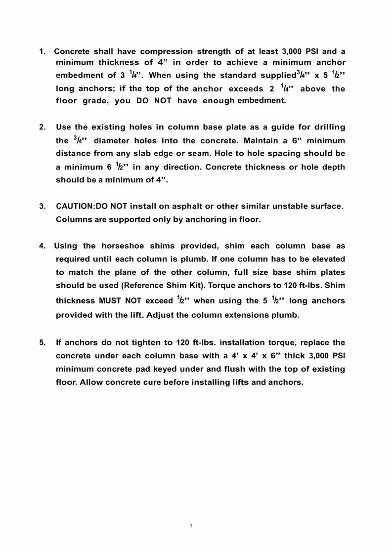
1. Concrete shall have compression strength of at least 3,000 PSI and a minimum thickness of 4” in order to achieve a minimum anchor embedment of 3 1/4”. When using the standard supplied3/4” x 5 1/2” long anchors; if the top of the anchor exceeds 2 1/4” above the floor grade, you DO NOT have enough embedment.
2. Use the existing holes in column base plate as a guide for drilling
the 3/4” diameter holes into the concrete. Maintain a 6” minimum distance from any slab edge or seam. Hole to hole spacing should be
a minimum 6 1/2” in any direction. Concrete thickness or hole depth should be a minimum of 4”.
3. CAUTION:DO NOT install on asphalt or other similar unstable surface. Columns are supported only by anchoring in floor.
4. Using the horseshoe shims provided, shim each column base as required until each column is plumb. If one column has to be elevated to match the plane of the other column, full size base shim plates should be used (Reference Shim Kit). Torque anchors to 120 ft-lbs. Shim
thickness MUST NOT exceed 1/2” when using the 5 1/2” long anchors
provided with the lift. Adjust the column extensions plumb.
5. If anchors do not tighten to 120 ft-lbs. installation torque, replace the concrete under each column base with a 4’ x 4’ x 6” thick 3,000 PSI minimum concrete pad keyed under and flush with the top of existing floor. Allow concrete cure before installing lifts and anchors.
8
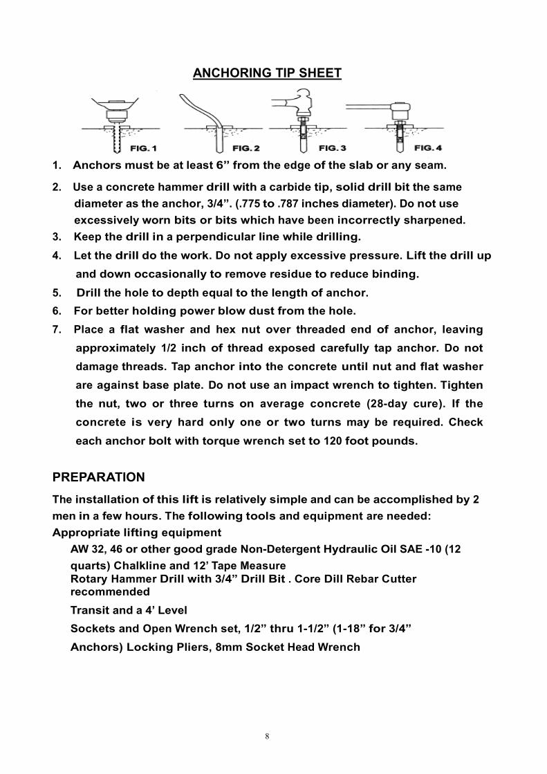
ANCHORING TIP SHEET
1. Anchors must be at least 6” from the edge of the slab or any seam.
2. Use a concrete hammer drill with a carbide tip, solid drill bit the same diameter as the anchor, 3/4”. (.775 to .787 inches diameter). Do not use excessively worn bits or bits which have been incorrectly sharpened.
3. Keep the drill in a perpendicular line while drilling.
4. Let the drill do the work. Do not apply excessive pressure. Lift the drill up and down occasionally to remove residue to reduce binding.
5. Drill the hole to depth equal to the length of anchor.
6. For better holding power blow dust from the hole.
7. Place a flat washer and hex nut over threaded end of anchor, leaving approximately 1/2 inch of thread exposed carefully tap anchor. Do not damage threads. Tap anchor into the concrete until nut and flat washer are against base plate. Do not use an impact wrench to tighten. Tighten the nut, two or three turns on average concrete (28-day cure). If the concrete is very hard only one or two turns may be required. Check each anchor bolt with torque wrench set to 120 foot pounds.
PREPARATION
The installation of this lift is relatively simple and can be accomplished by 2 men in a few hours. The following tools and equipment are needed: Appropriate lifting equipment
AW 32, 46 or other good grade Non-Detergent Hydraulic Oil SAE -10 (12 quarts) Chalkline and 12’ Tape Measure Rotary Hammer Drill with 3/4” Drill Bit . Core Dill Rebar Cutter recommended
Transit and a 4’ Level
Sockets and Open Wrench set, 1/2” thru 1-1/2” (1-18” for 3/4” Anchors) Locking Pliers, 8mm Socket Head Wrench

9
GENERAL INFORMATION
1. Any freight damage must be noted on the freight bill before signing and reported to the freight carrier with a freight claim established. Identify the components and check for shortages. If shortages are discovered, contact Shanghai Flying Tools Co., LTD immediately.
2. Consult building owner and/or architect’s plans when applicable to
establish the best lift location. The lift should be located on a relatively level floor with 4” minimum thickness, 3000 psi concrete slab that has been properly cured. There can be no cracks in the slab within 36” of the base plate location, and no seams in the foundation within 6” of its location! Remember: any structure is only as strong as the foundation on which it is located!
Check for ceiling clearance first to confirm the lift can be set up in your bay! STEP 1: After unloading the lift, place it near the intended installation
location. STEP 2: Remove the shipping bands and packing materials from the lift. The
power unit and cylinders will be unpacked from the top. STEP 3: Open the wrapping from the upper column and carefully remove the
parts from inside. Unbolt the column from the shipping brackets. STEP 4: Position the columns facing each other 107-1/4” inside base plates
Square the columns by measuring diagonally from corner points on base plates (within 1/4”).
STEP 5: Using a 3/4” diameter concrete drill, drill the anchor holes thru the main side column, installing anchors as you go. Use a block of wood or rubber mallet to drive anchor bolts in. Drill to a minimum depth of 4” to insure maximum holding power. Drilling thru concrete (recommended) will allow the anchor to be driven thru the bottom if the anchor needs to be replaced later.
STEP 6: Using a level, check column for side-to-side plumb and front-to-back plumb. If needed, use horseshoe shims provided by placing shims underneath the base plate and around the anchor bolt. This will prevent bending the column bottom plates (Shim thickness should not exceed 1/2” ). Tighten anchor bolts to 120 ft-lbs.
10
STEP 7: Install the overhead cross beam. Be sure to bolt them together by installing the bolts from inside the cross beam out. This is to avoid interference with the cable when operating the lift. Next, install the cross beam between two columns .
STEP 8: After fastening the cross beam, check and confirm that the remaining column is plumb.
STEP 9: Secure the remaining column by duplicating STEP 6 and STEP 7
STEP 10: Install the safety latch on both side columns. Connect the safety release cable between two latches. Check that the tension of the cable is tight. Pull the single point release handle several times and check the tension again by making sure both latches release at the same time when the handle is pulled.
STEP 11: Mount the power unit on the main side leg to the power unit bracket using the four 5/16” bolts and nuts. Connect the power unit to the fitting in- stalled on the back of the main leg by using a short hose supplied.
STEP 12: Connect the equalizing cables. Do not tighten at this stage of assembly.
NOTE!!! The cable stud that connects to the front right corner of the carriage should be connected first by pulling the stud throught the carriage hole and up where it is easy to be held by locking pliers. Pull the stud back into place after
threading at least 1/2” of the stud past the locknut. Connect the other ends to
the rear right corners of the carriage with at least 1/2” of thread showing past the lock nut (cables run on the inside of the carriage). It may be necessary to manually raise both carriages above the cylinder to provide enough space to use the locking pliers. Make sure the carriage is set in the LOCK position.
STEP 13: Adjust the carriage cable tension. This is accomplished by
tightening the carriage adjustment nut on top of each carriage. The rear carriage adjustment nut adjusts the opposite post carriage height. The left post carriage nut adjusts the right column carriage, and the right column carriage nut adjusts the left column carriage. Adjust each cable to approximately 1/2” side-to-side play. Check the latch releases to insure the carriage is still engaged in the appropriate latch.
STEP 14: Install all four swing arms, readjust the arm lock preinstalled to make sure that gear rack are engaging the moon gear on the arm properly.

11
STEP 15: Remove the vent plug from the power unit and fill the resevoir. Use a Ten Wdight (SAE-10) non-foaming, non-detergent hydraulic fluid. The unit will hold approximately twelve quarts of fluid.
STEP 16: Make the Electrical hookup to the power unit; 220V Single Phase. It is recommended that a 220 Volt, 30 Amp twist lock plug be installed in the power line just ahead of the power unit. Use wire capable of supporting a 30-amp circuit.
WARNING!!! The wiring must comply with local code. Have a certified electrician make the electrical hook-up to the power unit.
STEP 17: Locate each hole in the center of the up-rights, approximately 6” below the top edge, on the same side of the columns as the power unit. Install the two eye-bolts to the outside of each up-right with the hardware provided.
Insert the cable through the eye-bolt in the slave column side and secure with crimp fitting. Run cable across to the motor column side through the eye-bolt and down to the motor. Insert cable through the pull-pin on top of the motor and temporarily secure with locking pliers or small clamp. Operate lift and apply pressure to the safety cable to insure motor shuts ff
prior to any part of vehicle coming in contact with crossrail.
Adjust cadle if necessary and sevure with crimpfitting.Remove any excess cable with wire cutters.
STEP 19: Do not place any vehicle on the lift at this time. Cycle the lift up and down several times to insure latches engage properly and all air is re- moved from the system. To lower the lift, first raised the lift to clear the latches and then pull down the safety release handle to lower lift. lf latches func-tion out of sync,tighten the cable on the latch that engages first.
12
RAISE LIFT
1. Press button on power unit
The safety latch mechanism will ‘trip over’ when the lift raises and drop into each latch stop. To lock the lift you must press the Lower lever to relieve the hydraulic pressure and let the latch set tight in a lock position.
Note: It is normal for an empty lift to lower slowly - it may be necessary to add weight.
LOWER LIFT
1. Raise the lift until the latches clear the safety racks in both sides.
2. Pull down and hold the safety release handle.
WARNING!!! Always make sure latches on both sides clear the rack at same time
when pulling down the release handle by adjusting the cable.
3.Press the lowering lever at the power unit to lower the lift.
ATTENTION!!!
ALWAYS LOCK THE LIFT BEFORE GOING UNDER THE VEHICLE. NEVER ALLOW ANYONE TO GO UNDER THE LIFT WHEN RAISING OR LOWERING.
13
SAFETY PROCEDURES
Never allow unauthorized persons to operate lift. Thoroughly train new employees in the use and care of lift.
Caution-the power unit operates at high pressure.
Remove passengers before raising vehicle.
Prohibit unauthorized persons from being in shop area while lift is in use.
Total lift capacity is 4,000KG with 1,000KG per swivel pad. Do not exceed this capacity.
Prior to lifting vehicle,walk around the lift and check for any objects that might interfere with the operation of lift and safety latches; tools,air hoses, shop equipment.
When approaching the lift with a vehicle, center the vehicle between the columns so that the tires will clear the swing arms easily .Slowly drive the vehicle up between the posts. Have someone outside the vehicle guide the driver.
Always lift vehicle using all four pads.
Never use lift to raise one end or one side of vehicle.
Raise vehicles about 3" and check stability by rocking.
Prior to lowering vehicle, walk around the lift and check for any objects that might interfere with the operation of lift and safety latches; tools, air hoses, shop equipment. Swing the arms out and slowly drive the vehicle out. Have someone outside the vehicle guide the driver.

14
MAINTENANCE SCHEDULE The following periodic maintenance is the suggested minimum requirements and minimum intervals; accumulated hours or monthly period, which ever comes sooner. lf you hear a noise not associated with normal lift operation, or, if there is any indication of impending lift failure-CEASE OPERATION IMMEDLATELY!- inspect, correct and/or replace parts as required.
WARNING!!!
OSHA AND ANSI REQUIRE USERS TO INSPECT LIFTING EQUIPMENT AT THE START OF EVERY SHIFT.THESE AND OTHER PERIODIC INSPECTIONS ARE THE RESPONSIBILITY OF THE USER.
DAILY PRE-OPERATION CHECK(8 HOURS)
The user should perform daily check.
ATTENTION! Daily check of safety latch system is very important-the discovery of a potential device failure could prevent expensive property damage, lost production time, serious personal injury, and even death.
Check safety lock audibly and visually while in operation
Check safety latches for free movement and full engagement with rack.
Check hydraulic connections, and hoses for leakage.
Check chain connections-bends, cracks-and loose links.
Check cables connections-bends, cracks-and looseness.
Check for frayed cables in both raised and lowered position.
Check snap rings at all rollers and sheaves.
Check bolts, nuts, and screws and tighten if needed.
Check wiring & switches for damage.
Keep base plate free of dirt, grease or any other corrosive substances
Check floor for stress cracks near anchor bolts.
Check swing arm restraints.

15
WEEKLY MAINTENANCE(40 HOURS)
Check anchor bolts torque to 120 ft-lbs for the 3/4"anchor bolts. Do not use impact wrench.
Check floor for stress cracks near anchor bolts Check hydraulic oil level. Check and tighten bolts, nuts, and screws. Check cylinder pulley assembly for free movement or excessive wear on cylinder yoke or pulley pin Check cable pulley for free movement and excessive wear.
YEARLY MAINTENANCE
Lubricate chain. Grease rub blocks and column surface contacting rub blocks. Change the hydraulic fluid-good maintenance procedure makes it mandatory to keep hydraulic fluid clean. No hard fast rules can be established;-operating temperature, type of service, contamination levels, filtration, and chemical composition of fluid should be considered. lf operating in dusty environment shorter interval may be required.
The following items should only be performed by a trained maintenance expert.
Replace hydraulic hoses. Replace chains and rollers. Replace cables and sheaves. Replace or rebuild air and hydraulic cylinders as required. Replace or rebuild pumps / motors as required. Check hydraulic cylinder rod and rod end(threads)for deformation or damage.
Relocating or changing components may cause problems, Each component in the system must be compatible; an undersized or restricted line will cause a drop in pressure. All valve, pump, and hose connections should be sealed and/or capped until just prior to use. Air hoses can be used to clean fittings and other components. However, the air supply must be filtered and dry to prevent contamination. Most important-cleanliness-contamination is the most frequent cause of malfunction or failure of hydraulic equipment.
16
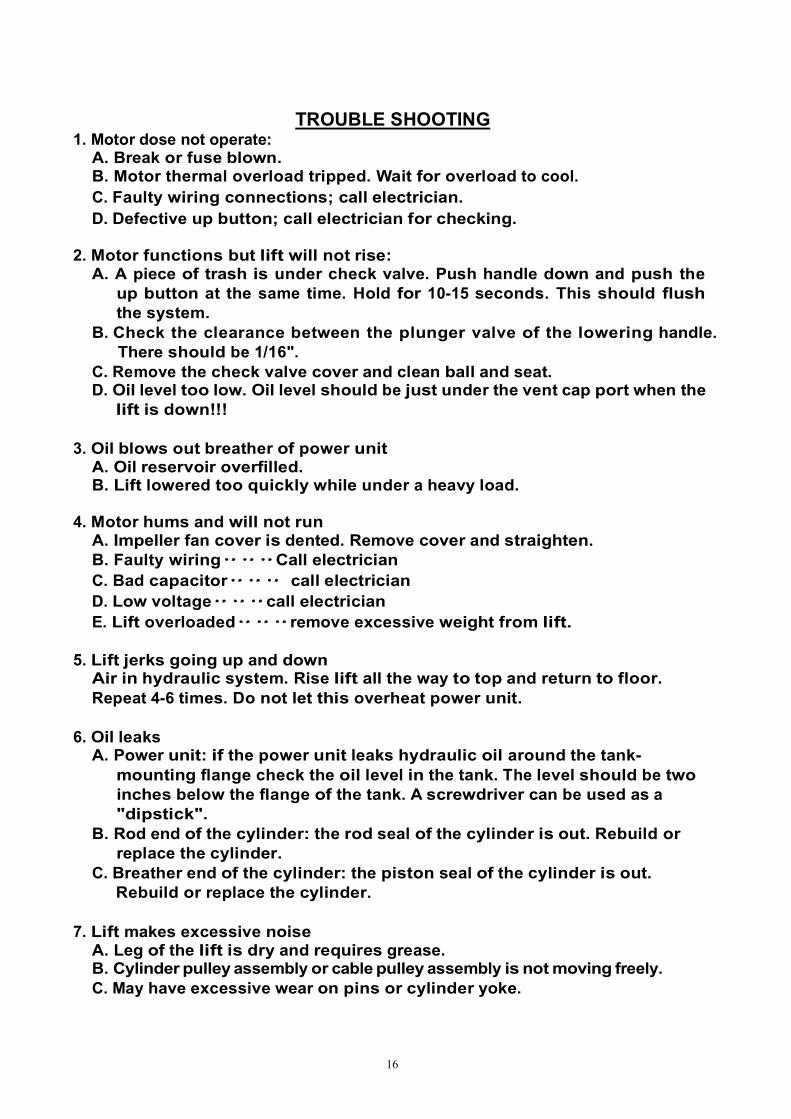
TROUBLE SHOOTING 1. Motor dose not operate:
A. Break or fuse blown. B. Motor thermal overload tripped. Wait for overload to cool. C. Faulty wiring connections; call electrician. D. Defective up button; call electrician for checking.
2. Motor functions but lift will not rise:
A. A piece of trash is under check valve. Push handle down and push the up button at the same time. Hold for 10-15 seconds. This should flush the system.
B. Check the clearance between the plunger valve of the lowering handle. There should be 1/16".
C. Remove the check valve cover and clean ball and seat. D. Oil level too low. Oil level should be just under the vent cap port when the
lift is down!!!
3. Oil blows out breather of power unit A. Oil reservoir overfilled. B. Lift lowered too quickly while under a heavy load.
4. Motor hums and will not run
A. Impeller fan cover is dented. Remove cover and straighten. B. Faulty wiring‥‥‥Call electrician C. Bad capacitor‥‥‥ call electrician D. Low voltage‥‥‥call electrician E. Lift overloaded‥‥‥remove excessive weight from lift.
5. Lift jerks going up and down
Air in hydraulic system. Rise lift all the way to top and return to floor. Repeat 4-6 times. Do not let this overheat power unit.
6. Oil leaks
A. Power unit: if the power unit leaks hydraulic oil around the tank- mounting flange check the oil level in the tank. The level should be two inches below the flange of the tank. A screwdriver can be used as a "dipstick".
B. Rod end of the cylinder: the rod seal of the cylinder is out. Rebuild or replace the cylinder.
C. Breather end of the cylinder: the piston seal of the cylinder is out. Rebuild or replace the cylinder.
7. Lift makes excessive noise
A. Leg of the lift is dry and requires grease. B. Cylinder pulley assembly or cable pulley assembly is not moving freely. C. May have excessive wear on pins or cylinder yoke.
17
OWNER / EMPLOYER RESPONSIBILE TIES The Owner/Employer:
Shall established procedures to periodically maintain, inspect and care for the lift in accordance with the manufactures recommended procedures to ensure its' continued safe operations.
Shall provide necessary lockout / tagouts of energy sources per ANSI Z244.1-1982 before beginning any lift repairs
Shall not modify the lift in any manner without prior written consent of the manufacturer.
Shall display the operating instructions, "Lifting lt Right" and "Safety Tips" supplied with the lift in a conspicuous location in the lift area convenient to the operator.
Shall insure that lift operators are instructed in the proper and safe use and operation of the lift.

18

19

20
21
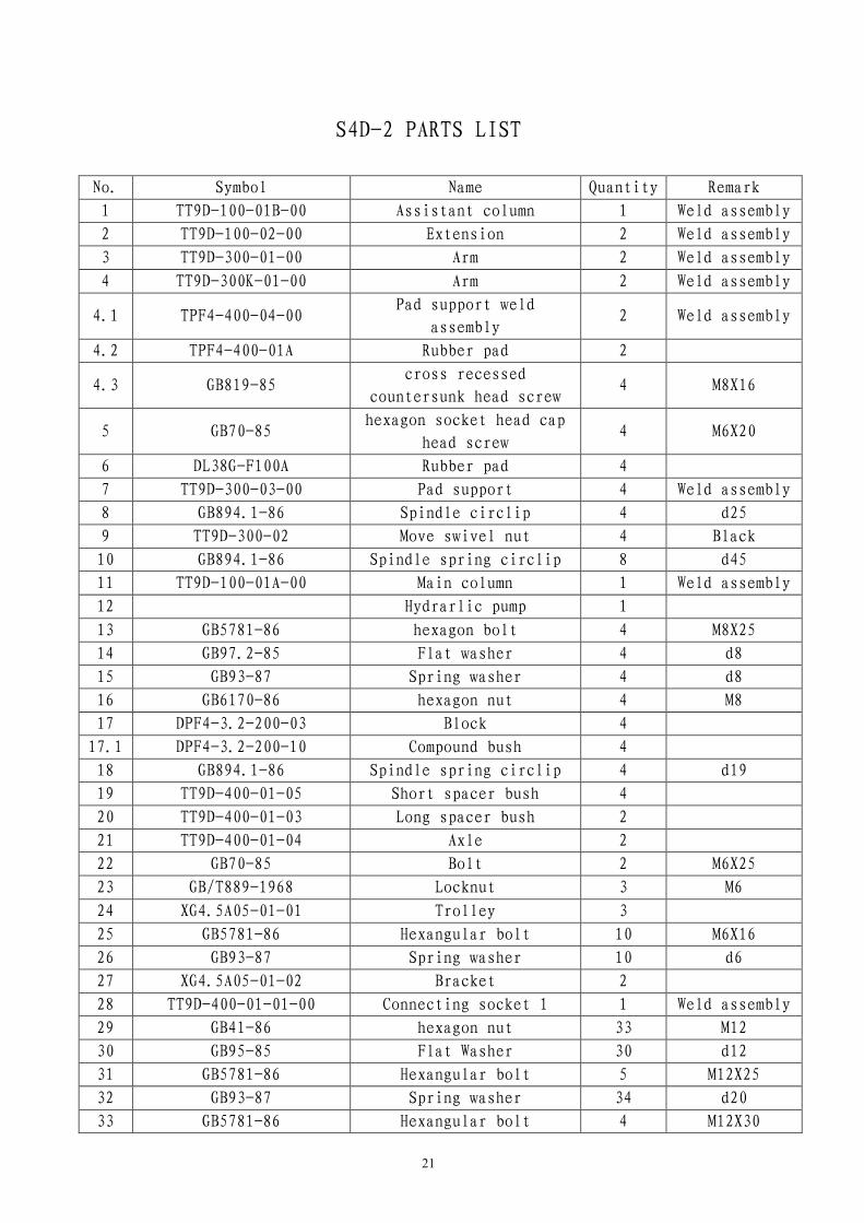
S4D-2 PARTS LIST
No. Symbol Name Quantity Remark
1 TT9D-100-01B-00 Assistant column 1 Weld assembly
2 TT9D-100-02-00 Extension 2 Weld assembly
3 TT9D-300-01-00 Arm 2 Weld assembly
4 TT9D-300K-01-00 Arm 2 Weld assembly
4.1 TPF4-400-04-00 Pad support weld
assembly 2 Weld assembly
4.2 TPF4-400-01A Rubber pad 2
4.3 GB819-85 cross recessed
countersunk head screw 4 M8X16
5 GB70-85 hexagon socket head cap
head screw 4 M6X20
6 DL38G-F100A Rubber pad 4
7 TT9D-300-03-00 Pad support 4 Weld assembly
8 GB894.1-86 Spindle circlip 4 d25
9 TT9D-300-02 Move swivel nut 4 Black
10 GB894.1-86 Spindle spring circlip 8 d45
11 TT9D-100-01A-00 Main column 1 Weld assembly
12 Hydrarlic pump 1
13 GB5781-86 hexagon bolt 4 M8X25
14 GB97.2-85 Flat washer 4 d8
15 GB93-87 Spring washer 4 d8
16 GB6170-86 hexagon nut 4 M8
17 DPF4-3.2-200-03 Block 4
17.1 DPF4-3.2-200-10 Compound bush 4
18 GB894.1-86 Spindle spring circlip 4 d19
19 TT9D-400-01-05 Short spacer bush 4
20 TT9D-400-01-03 Long spacer bush 2
21 TT9D-400-01-04 Axle 2
22 GB70-85 Bolt 2 M6X25
23 GB/T889-1968 Locknut 3 M6
24 XG4.5A05-01-01 Trolley 3
25 GB5781-86 Hexangular bolt 10 M6X16
26 GB93-87 Spring washer 10 d6
27 XG4.5A05-01-02 Bracket 2
28 TT9D-400-01-01-00 Connecting socket 1 1 Weld assembly
29 GB41-86 hexagon nut 33 M12
30 GB95-85 Flat Washer 30 d12
31 GB5781-86 Hexangular bolt 5 M12X25
32 GB93-87 Spring washer 34 d20
33 GB5781-86 Hexangular bolt 4 M12X30

22
34 TT9D-400-01-02-00 Connecting socket 2 1 Weld assembly
35 Rubber sponge washer 1
36 DL38G-L103A spindle 2
37 DL38G-L102A Rod 1
38 DL38G-L101A Rod seat 2
39 GB896-86 Open spindle circlip 2 d15
40 TT9D-600-09-00 Vitta support 2 Weld assembly
42 GB5781-86 Hexangular bolt 24 M12X40
43 GB96-85 Flat washer 32 d12
44 Journey switch 1 TZ-8104
45 TPF4-400-06-00 Spindle weld 4 Weld assembly
46 Ball handle 4 Black
bakelite ball
47 TPF4-200-11-01 Rack shaft 4
48 GB97.2-85 Flat washer 8 d10
49 GB93-87 Spring washer 4 d10
49.1 GB6170-86 Nut 4 M10
50 TPF4-200-11-04 Gear rack 4
51 TPF4-200-11-05 Baffle 4
52 TPF4-200-11-02 Spring 4
53 GB91-86 Open pin 4 d2x25
54 TT9D-500-07-00 Assistant cap 1 Weld assembly
55 TT9D-500-01-00 Main cap 1 Weld assembly
56 GB95-85 Flat washer 8 d6
57 GB818-85 Cross Recess Head Screw 16 M6X8
58 TPF4-500-05 Direct outside fitting 1
59 TPF4-500-07 Hydraulic fitting 1
60 TPF4-500-08 Washer 1
61 TPF4-500-09 Nut 2
62 TT9D-600-02 Hydraulic hose 1 L=320
64 TT9D-600-06 Three-way connection 1
65 TT9D-500-08-00 Safety thin steel cable 1 subassembly
66 TT9D-600-04 Hydraulic hose 1 L=1580
67 TT9D-600-03 Hydraulic hose 1 L=8520
68 TPF4-500-06 Direct inside and
outside fitting 2
69 TT9D-600-05-00 Straight joint 2 subassembly
70 GB819-85 Cross recessed
countersunk head screw 2 M6X10
71 TT9D-100-03-00 Rope sheave root spindle 2 Weld assembly
72 XG4.5A01-03 Trolley 2
73 Compound bush 2
74 Hydraulic cylinder 2 subassembly
75 TT9D-600-01 Steel cable 2 L=10M

23
76 GB95-85 Flat washer 4 D20
77 Hexangular nut 4 3/4"-16
78 TT9D-200-01-00 Carriage 2 Weld assembly
78.1 TT9D-200-03 Cover 2
79 TPF4A-200-12 Nylon 16
80 XG4.5A05-07 Main torsional spring 2
81 XG45A05-11 spindle 2
82 TT9D-500-04-00 Cliver 2
83 TT9D-500-02-03B sector 1
84 TT9D-500-06 nut 1
85 TT9D-500-05 spindle 1
86 XG45A05-08 Assistant torsional
spring 1
87 XG45A05-10 Cover 2
88 GB70-85 Sockets bolt 2 M10X16
89 Expand bolt 10 φ19
90 XG4.5A05-02-02 Bracket 1
91 GB5781-86 Hexangular bolt 1 M6X35
92 XG4.5A05-09 Cover 2
93 JN/T7271.1-94 Ball handle 1
94 TT9D-500-03 Handle 1
95 GB6170-86 hexagon nut 1 M10
96 GB95-85 Flat washer C 1 D10
97 GB93-87 Spring washer 1 D10
98 TT9D-500-02-00 Sector 1 Weld assembly
99 GB5781-86 Hexangular bolt 1 M6X35
100 GB6170-86 hexagon nut 1 M6