s scientific research associates, inc. - nasa · pdf files scientific research associates,...
TRANSCRIPT
. , - s
Scientific Research Associates, inc. 50 Nye Road, P.O. Box 1058 Glastonbury, Connecticut 06033 (203) 659-0333
a
VELOCIMETRY WITH REFRACTIVE INDEX MATCHING
FOR COMPLEX FLOW CONFIGURATIONS
B.E. Thompson, C. Vafidist and J.H. Whitelawtt
S c i e n t i f i c Research Assoc ia tes , Inc.
Glastonbury, CT 06033
August 1987
Final Report (SBIR Phase I )
Prepared under Contract NAS8-37320
Prepared for :
NASA
George C. Marshall Space Fl ight Center
Huntsville, Alabama
(NASA-CR-179160) VELUCIBETbY h I I E 887-27 1 5 1
BEFBACTIVE I I J G E X 2!ATCBIBG P G 6 CCBFLEX f L O U ( S c i e n t i f i c 6esrarch Associates) 43 p Onclas
a v a i l : NlJS i fC A C 3 / B F A01 CSCL 20D 63/34 0092575
https://ntrs.nasa.gov/search.jsp?R=19870017719 2018-05-20T14:24:54+00:00Z
VELOCIMETRY WITH REFRACTIVE INDEX PATCHING FOR COMPLEX nOW CONFIGURATIONS
PHASE I FINAL REPORT
B.E. Thompson, C. Vafidis t and J.H. Whitelawtt S c i e n t i f i c Research Assoc ia tes , Inc.
Glastonbury, CT 06033
Projec t Summary
The purpose of t he Phase I and I1 r e sea rch i s t o develop r e f r a c t i v e -
index-matching techniques f o r ve loc i ty measurements i n the l a rge Reynolds
number complex flows found i n rocket engines. I n t h e Phase I s tudy, t h e
f e a s i b i l i t y of ob ta in ing d e t a i l e d ve loc i ty f i e l d measurements i n l a rge
Reynolds number flow of t he SSME main i n j e c t o r bowl was demonstrated us ing
laser velocimetry and the developed refractive-index-matching technique. An
experimental system t o provide appropr ia te flow rates and temperature con t ro l
of refractive-index-matching f l u i d was designed and t e s t e d . Veloci ty
measurements were obtained with laser velocimetry i n a spec ia l ly-prepared
complex model of t he SSME main i n j e c t o r bowl. T e s t r e s u l t s are presented t o
e s t a b l i s h t h e f e a s i b i l i t y of ob ta in ing a c c u r a t e v e l o c i t y measurements t h a t
map the e n t i r e f i e l d inc luding the flow through the LOX’post bundles:
mean v e l o c i t y , turbulence i n t e n s i t y and s p e c t r a l r e s u l t s are presented. The
r e s u l t s i n d i c a t e t h a t a s u i t a b l e f l u i d and c o n t r o l system is f e a s i b l e f o r the
r e p r e s e n t a t i o n of complex rocket-engine conf igu ra t ions and t h a t measurements
of v e l o c i t y c h a r a c t e r i s t i c s can be obtained without t he o p t i c a l access
r e s t r i c t i o n s normally a s soc ia t ed with laser velocimetry.
sample
The ref ractive-index-matching technique considered he re needs t o be
f u r t h e r developed and extended t o represent o t h e r rocket-engine flows where
c u r r e n t methods e i t h e r cannot measure with adequate accuracy or they f a i l .
P o t e n t i a l i n d u s t r i a l developments would inc lude the provis ion of r e f r a c t i v e -
index-matching r i g s , models, and assoc ia ted ins t rumenta t ion . The
refractive-index-matching approach could a l s o be used on a commercial b a s i s
t o provide valuable experimental results i n a wide range of complex i n t e r n a l
geometr ies i nc lud ing , f o r example, rocket-engine duc t s , manifold, pumps,
t u r b i n e hea t exchangers and bear ings.
a Post Doctoral Assistant, Imperial College t t P ro fes so r Heat Transfer , Imperial College
- 1-
INTRODUCTION
The measurement of i n t e r n a l flows confined by complex boundaries is o f t e n
r e s t r i c t e d by a c c e s s i b i l i t y d i f f i c u l t i e s .
when using sensor probes i n narrow flow passages or t o o p t i c a l r e s t r i c t i o n s
imposed by the geometry of t he model boundaries when using o p t i c a l measurement
techniques. The non-intrusive nature of laser velocimeters (LV), combined with
t h e i r i n s e n s i t i v i t y t o f l u i d p rope r t i e s and flow cond i t ions , renders t h e i r use
p a r t i c u l a r l y a t t r a c t i v e f o r t he study of complex flow conf igura t ions , provided
t h a t adequate o p t i c a l access can be ensured.
o r t r anspa ren t models may w e l l provide t h e necessary o p t i c a l access i n many
flow conf igu ra t ions but i n some cases t h e presence of mul t ip le s o l i d
boundaries , o f t e n with complex surface cu rva tu re , poses a d d i t i o n a l measurement
l i m i t a t i o n s . These d i f f i c u l t i e s arise from differ .ences i n r e f r a c t i v e ind ices
of t he f l u i d and the boundaries of t h e t r anspa ren t model along the path of the
l a s e r beams which form the measurement volume of t he laser velocimeter. These
may a f f e c t the measurement p o s i t i o n and s e n s i t i v i t y f a c t o r of the laser
velocimeter , but i n most cases they w i l l prevent measurement because the laser
beams w i l l not i n t e r s e c t and w i l l not form the i n t e r f e r e n c e measurement volume.
The s imples t poss ib le case of the e f f e c t of a curved o p t i c a l boundary of a
c y l i n d r i c a l duct on the measurement p o s i t i o n and s e n s i t i v i t y f a c t o r of a l a s e r
velocimeter i s ou t l ined i n Appendix 1 of t h i s repor t . Only measurements of t h e
a x i a l and t r a n s v e r s a l ve loc i ty components are poss ib le i n t h i s case and even
these require co r rec t ions t o be appl ied. I f t he plane of t he laser beams does
not coincide with either the a x i a l or lateral piane of t he c y l i n d r i c a l duc t , a
laser-beam i n t e r s e c t i o n w i l l not occur un le s s t he r e f r a c t i v e index of a l l media
wi th non-planar o p t i c a l boundaries is the same. It is on t h i s observat ion t h a t
t he p r i n c i p l e of t he refractive-index-matching technique i s based.
These may be due t o flow o b s t r u c t i o n
The use of o p t i c a l l y f l a t windows
0
The absolu te r e f r a c t i v e index (n) of a t ransparent medium is defined as
the r a t i o of t he v e l o c i t y of propagation of l i g h t waves i n vacuum t o t h a t i n
t he medium and depends on l i g h t wavelength and temperature (Ref. 1). Most
information on f l u i d s with r e f r a c t i v e i n d i c e s matching those of t r anspa ren t
s o l i d s comes from c r y s t a l microscopy and f o r e n s i c g l a s s i d e n t i f i c a t i o n methods
(e.g., Refs. 2, 3). The use of r e f r a c t i v e index l i q u i d s i n f l u i d flow s t u d i e s ,
however, r equ i r e s o ther f l u i d p rope r t i e s , such as v i s c o s i t y and dens i ty , t o be a with in acceptab le margins.
-2-

One of the p ioneer ing app l i ca t ions of ref ractive-index-matching i n LV measurements concent ra ted on a simpler c i rcular duct f low wi th emphasis on t h e
near w a l l regions (Ref 4) This work concluded t h a t "disturbance-f ree
measurements i n t h e near w a l l region of t h e pipe were poss ib l e , u s ing t h e
refractive-index-matching technique and were i n agreement wi th t h e o r e t i c a l
r e s u l t s der ived from t h e momentum equations". Measurements as c l o s e as 300 pm
near t o the w a l l were obtained as opposed t o 1-1.5 mn when using convent ional
hot-wire o r hot-fi lm senso r probes. The l i q u i d used t o match t h e r e f r a c t i v e
index of the g l a s s wall (Duran 30 or Pyrex, nD = 1.4718) was a mixture of
l i g h t f u e l o i l (nD = 1.463) and d ibuty lphtha la te .
matched the r e f r a c t i v e index of the g la s s wi th in hi = but i ts v i s c o s i t y
was h igher than t h a t of water. A number of s u i t a b l e f l u i d s and mixtures t o
match the r e f r a c t i v e index of g l a s s were a l s o examined and c l a s s i f i e d according
t o t o x i c i t y , chemical a g g r e s s i v i t y and f lammabil i ty . In gene ra l , t h e s e f l u i d s
were organic so lven t s , not s u i t a b l e fo r use with a c r y l i c components . A more r ecen t a p p l i c a t i o n of-refractive-index-matching (Ref. 5 )
0
The r e s u l t i n g mixture
concent ra ted i n v e l o c i t y f i e l d measurements i n a rod bundle and between
c y l i n d r i c a l roughness e lements i n boundary layers . Most of t h e o p t i c a l
boundaries were made of g l a s s and the matching f l u i d s were p r imar i ly mineral
and s i l i c o n e o i l s . This r e s u l t e d i n h igh v i s c o s i t i e s and t h e t y p i c a l Reynolds
numbers f o r these experiments were i n t he laminar regime.
Considering t h e d i f f i c u l t i e s of manufacturing complex models with g l a s s ,
t he a l t e r n a t i v e choice leads t o c lear cast a c r y l i c s which have e x c e l l e n t
machinabi l i ty and t ransparency. Their disadvantage l ies wi th t h e i r
v u l n e r a b i l i t y t o chemdcal agents such as inorganic so lvents . The t y p i c a l
r e f r a c t i v e index of a cast a c r y l i c i s about 1.5 f o r t h e sodium D l i n e a t 20' C
(Ref. 6) , while i ts l i g h t t ransmit tance is 92% a t A = 600 nm, independent of
t h i ckness and makes it p e r f e c t l y s u i t a b l e f o r f a b r i c a t i o n of t r anspa ren t flow
models. An example of the use of ac ry l i c models f o r flow s t u d i e s us ing LV and
refractive-index-matching techniques is given i n (Ref. 7) where a number of
converging s w i r l chambers were examined. The f l u i d used f o r the matching of
the r e f r a c t i v e index of t h e cast a c r y l i c w a s a mixture of o i l and t u r p e n t i n e
with te t rahydronaphthalene and allowed d e t a i l e d scanning of the flow f i e l d ,
d e s p i t e the i r r e g u l a r i t i e s of t he f l o w boundaries.
-3-
Prel iminary s t u d i e s of ref ractive-index-matching technique are repor ted i n Refs. 8-11 and demonstrate t h e usefulness of t h e technique as a r e sea rch t o o l .
The flow f i e l d behind a confined d i s c i n a c i r c u l a r duct has been s tud ied i n
d e t a i l (Ref . 8 ) us ing refractive-indexmatching techniques and t h e r e s u l t s were
compared t o those obtained i n a i r flow (Ref. 12) and were found t o be i n very
good agreement. Furthermore, t he f e a s i b i l i t y of ob ta in ing a c c u r a t e v e l o c i t y
measurements i n two-phase flows with high p a r t i c l e concen t r a t ion (up t o l O O X
s o l i d volume f r a c t i o n s ) was demonstrated i n Refs. 9 and 10 by matching t h e
r e f r a c t i v e index of the t r anspa ren t so l id p a r t i c l e s (Diakon sphe res ) thus
minimizing t h e i r e f f e c t on the l a s e r beam path.
Laser velocimetry with ref rac t ive- indexmatching w a s a l s o used f o r s ing le -
and two-phase flow measurements around t h e t r anspa ren t b lades of t h e impel le r
of a mixer (Ref. 11) and t h e mapping of t he s teady flow f i e l d i n s i d e a
t r anspa ren t model of a d i r e c t e d po r t of an i n t e r n a l combustion engine.
favorable a p p l i c a t i o n of t h e technique is t h e flow through rod bundles of hea t
exchangers, wi th emphasis on t h e flow induced v i b r a t i o n s of t he rods , as
repor ted i n (Ref . 1 4 ) .
Another
The evidence i n t h e l i t e r a t u r e to d a t e sugges ts t h a t re f rac t ive- index-
matching is a powerful technique which can al low accura t e v e l o c i t y f i e l d
measurements t o be obta ined wi th l a s e r velocimetry i n flow conf igu ra t ions with
mul t ip l e flow boundaries and i r r e g u l a r geometry inc luding near-wall regions.
This prompted the present a t tempt t o develop and apply t h i s technique t o
measurement of the flow through a model of t he Main I n j e c t o r B o w l of t he Space
S h u t t l e Main Engine. This p a r t i c u l a r conf igu ra t ion is cha rac t e r i zed by
complex3 ty of the flow boundary, by l a r g e r Reynolds numbers than previous ly
used wi th refractive-index-matching techniques, and by t h e l a r g e number (over
600) of i n t e r n a l t ubu la r LOX pos t s which occupy most of the flow area. The
area of p a r t i c u l a r i n t e r e s t is the wake behind the LOX pos t s which, being so
c l o s e l y spaced, do not permit the use of any probe-based measurement technique.
a
The f e a s i b i l i t y of ob ta in ing d e t a i l e d v e l o c i t y f i e l d measurements i n the
l a r g e Reynolds number complex flow through a model of t he SSME Main I n j e c t o r
Bowl is demonstrated here us ing laser velocimetry and t h e developed r e f r a c t i v e -
index-matching technique. The design cons ide ra t ions of the experimental system
are descr ibed and sample measurements i n t h e complex flow f i e l d around t h e
s imulated LOX tubes are presented. Suggestions f o r improvements t o the
experimental procedures are made, based on t h e experience acqui red during t h i s
-4-

i n i t i a l study. This r e p o r t desc r ibes the des ign cons ide ra t ions of the
t r anspa ren t model of t h e SSME Main I n j e c t o r Bowl and t h e experimental f a c i l i t y
b u i l t around it f o r t he flow and temperature c o n t r o l of t h e r e f r a c t i v e -
index-matching-fluid. T e s t r e s u l t s are a l s o presented t o e s t a b l i s h t h e
f e a s i b i l i t y of ob ta in ing accu ra t e ve loc i ty measurements through the LOX posts :
sample v e l o c i t y and turbulence results are presented i n a 32% SSME I n j e c t o r
Bowl model conf igura t ion .
THE TRANSPARENT MODEL
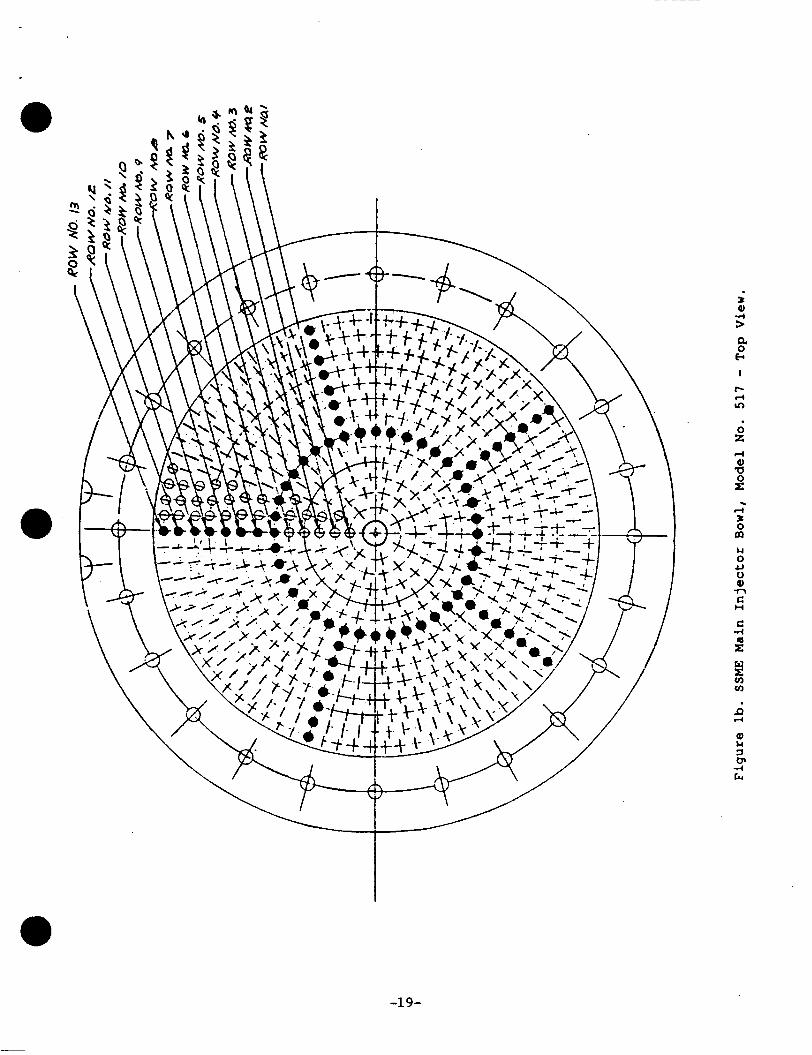
The model of the SSME Main In j ec to r Bowl used i n t h i s study o r i g i n a t e s
from t h e Model No. 517 Assembly used i n t h e NASA-MSFC water test f a c i l i t y . A
schematic of t h i s model is shown i n Fig. 1 and r ep resen t s a half-scale model of
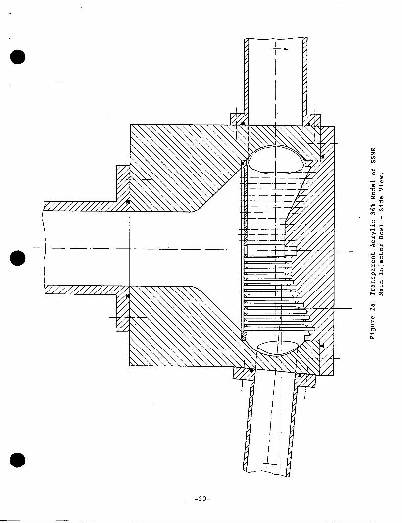
the actual SSME Main Engine. The t r anspa ren t model b u i l t f o r the r e f r a c t i v e -
index-matching s t u d i e s is shown i n Figs. 2a and 2b. Its i n t e r n a l geometry is
i d e n t i c a l t o t h a t of t h e Model No. 517, s c a l e d down t o 64%. This smaller s i z e
was chosen i n order t o reduce the volume of t he r e f r a c t i v e index f l u i d , while
t he exac t s c a l i n g w a s d i c t a t e d by the a v a i l a b i l i t y of clear cast a c r y l i c rods
of t h e requi red diameter (3 mn), i n order t o s imula te the LOX posts. The
e x t e r n a l shape of t h e t r anspa ren t model i s r ec t angu la r t o improve o p t i c a l
a c c e s s i b i l i t y . The material used is c l e a r cast a c r y l i c with r e f r a c t i v e index
nD = 1.4893 at 23.4OC f o r &-Ne laser l i g h t a t X = 632.8 nm.
model underwent a 38-hour anneal ing process a t 85" C i n order to r e l i e v e the
mechanical stresses induced by t h e machining. This is an e s s e n t i a l process
s i n c e it was found that the f l u i d contains an inorganic so lvent which a t t a c k s
the a c r y l i c , p r e f e r e n t i a l l y i n regions of concent ra ted stresses.
0 The f i n i s h e d
The LOX post assembly i s simulated by 464 s o l i d rods made of the same
a c r y l i c as t h e Bowl model and annealed a t 90" C f o r 12 hours. The p o s i t i o n i n g
of t hese rods is i d e n t i c a l t o t h a t of t h e Model No. 517 and provis ion was made
t o extend t h e i r number t o the o r i g i n a l 600, i f required. Due t o the small
diameter of the simulated LOX pos t s (3 mn), t he incorpora t ion of bleeding holes
a t t h e i r end as i n t h e Model No. 517 (see Fig. 3a) was not f e a s i b l e and,
i n s t e a d , an annular passage arrangement w a s adopted as shown i n Fig. 3b. The
whole LOX post assembly is supported between two aluminum p l a t e s and can be
e a s i l y removed from the model. It also inco rpora t e s two s h i e l d s of similar
geometry t o those of t he Model No. 517, made of thermo-formed a c r y l i c s h e e t ,
-5-

but pos i t ioned only i n f r o n t of t he e x i t s of t h e two p a i r s of t he t r a n s f e r
ducts. Provis ion w a s made t o enable the p o s i t i o n i n g of a d d i t i o n a l LOX s h i e l d s *
around the LOX post assembly i f required.
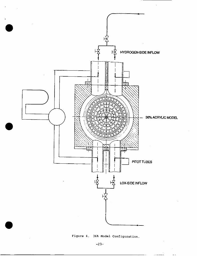
The two pa i rs of t r a n s f e r duc t s of t h e o r i g i n a l model are s imula ted by two
p a i r s of pipes extending more than twenty d iameters upstream of the model
(Fig. 4) so as t o ensure swi r l - f r ee , f u l l y developed t u r b u l e n t flow a t t h e
e n t r y t o , t h e model. This a l s o allowed the use of P i t o t probes f o r t he
monitoring of t h e flow r a t e i n each of t h e t r a n s f e r ducts. F i n a l l y , the e x i t
of the model c o n s i s t s of a s t r a i g h t pipe, extending t e n diameters downstream of
the model, t o avoid any upstream e f f e c t s from t h e rest of t h e p ip ing system.
THE EXPERIMENTAL FACILITY
The minimum flow rate through t h e model which would ensure Reynolds
numbers of approximately 20,000 i n the t r a n s f e r duc t s is three hundred l/min
and t h e combined volume of t h e piping a s s o c i a t e d wi th t h e model is e igh teen
l i tres. Considering the need f o r f ine temperature c o n t r o l of the r e f r a c t i v e
index f l u i d , a maximum of one r e c i r c u l a t i o n of t h e f u l l amount of f l u i d every
15 s was es t imated t o be s a t i s f a c t o r y , ( t h i s l i m i t was set i n conjunct ion with
the choice of t h e hea t ing element a s d i scussed below), and a minimum f l u i d
volume of 150 l i t res i n t h e system was chosen.
(I)
The flow c i r c u i t and arrangement of t h e temperature c o n t r o l l e d s t o r a g e
tank are shown i n Fig. 5. It is made of galvanized steel shee t and is equipped
with a hea t ing element of 2.6 kW and a coo l ing c o i l pos i t i oned eo-axially wi th
t h e hea te r . The power of t he heating element is s u f f i c i e n t t o raise the
temperature of t h e 150 litres of c i r c u l a t i n g f l u i d by 0.2' C i n 15 s and e a s i l y
ba lances the heat l o s s e s of t he system. Two independent c e n t r i f u g a l pumps
d r i v e t h e f l u i d t o the 'oxygen' and 'hydrogen' s i d e of t h e model through a
series of c o n t r o l and by-pass valves. The flow through t h e l a t t e r is a l s o used
t o ensure continuous s t i r r i n g of the working f l u i d i n t h e s to rage tank.
The temperature of t h e f l u i d is monitored a t the e x i t of the model by a
platinum f i l m (Pt100) sensor and is c o n t r o l l e d by a PID (Propor t iona l - In tegra l -
D i f f e r e n t i a l ) temperature c o n t r o l l e r . The primary output of the c o n t r o l l e r
ope ra t e s t he hea t ing element while a secondary output enab le s , v i a a so lenoid
va lve , t he flow of t a p water through the cool ing c o i l . This t y p e of
temperature c o n t r o l , combined with the thermal i n e r t i a of t he sys t em and t h e
-6-
r e l a t i v e l y low temperatures involved ( l e s s than 27' C) ensures temperature
@ s t a b i l i t y b e t t e r t han 0.05'C.
The flow rate i n the t r a n s f e r ducts is measured by four s e p a r a t e P i t o t
probes, us ing water f i l l e d U-tube manometers.
weight between water and r e f r a c t i v e index f l u i d (1 kg / l vs. 0.895 k g / l ) was
advantageous wi th r e spec t t o t h e s e n s i t i v i t y of t h i s simple monitoring system.
The small d i f f e r e n c e i n s p e c i f i c
SYSTEM PERFORMANCE
Pre l iminary tests of the experimental f a c i l i t y revea led d i f f i c u l t i e s
a s s o c i a t e d with a e r a t i o n of the r e f r a c t i v e index f l u i d , which p resen t s a
tendency t o foam.
s to rage tank and modifying the r e tu rn p ipe t o prevent a e r a t i o n . Another
d i f f i c u l t y a s s o c i a t e d wi th t h e p rope r t i e s of t h e working f l u i d is i ts tendency
t o p e n e t r a t e e a s i l y through ord inary pipe f i t t i n g s . It appears t h a t t h e most
s u i t a b l e p ip ing system would c o n s i s t of copper p ipes with compression f i t t i n g s .
This problem was cured by r a i s i n g t h e f l u i d l e v e l i n t h e
The maximum flow rate achieved through each of t he t r a n s f e r duc t s was
90 l/min and 170 l/min a t the 'oxygen' and 'hydrogen' s i d e r e s u l t i n g i n
Reynolds numbers of 32,000 and 45,000, r e spec t ive ly . A t t hese flow rates t h e
temperature c o n t r o l system a l s o performed s a t i s f a c t o r i l y , main ta in ing cons t an t
temperature wi th in measurement accuracy, ( b e t t e r than 0.1' C).
rl)
THE REFRACTIVE I N D E X FLUID
The f l u i d shosen t o match the r e f r a c t i v e index of the cast a c r y l i c m d e l
f o r t h i s s tudy was a mixture of o i l of t u r p e n t i n e with 1, 2, 3,
4-tetrahydronaphthalene ( T e t r a l i n ) . This mixture was chosen f o r its low
t o x i c i t y and f lammabi l i ty , combined with i ts r e l a t i v e l y low cos t .
p a r t i c u l a r advantage of t h i s l i q u i d is t h e low v i s c o s i t y as compared wi th many
mineral o i l s which are s u i t a b l e f o r refractive-index-matching. Its main
disadvantage is t h e e f f e c t of the T e t r a l i n on the c a s t acry l ic , the su r face of
which s o f t e n s and crazes a f t e r s ix months i n con tac t with i t and d i s s o l v e s
a f t e r one year (Ref . 6 ) . The small content of T e t r a l i n i n the mixture (less
than 30%) and t h e thermal treatment of t h e t r a n s p a r e n t model, however, prolong
i t s l i f e t o more than one year without obvious e f f e c t s on the su r face qua l i t y .
Despite t he i n e r t na tu re of t h e mixture t h e r e are some precaut ions t o be taken
One
-7-
with respec t t o f i r e hazard and v e n t i l a t i o n of the working area. The fumes of
the mixture a r e i r r i t a t i n g and prolonged exposure may cause i n j u r y t o t h e
kidneys and lungs (Ref 1 5 ) . a The r e f r a c t i v e index of cast ac ry l i c ( 1 . 4 9 ) l ies between the r e f r a c t i v e
ind ices of the o i l of t u rpen t ine (1 .468) and T e t r a l i n ( 1 . 5 4 6 ) . It is the re fo re
f e a s i b l e t o o b t a i n a mixture of t h e two f l u i d s which, a t a given temperature ,
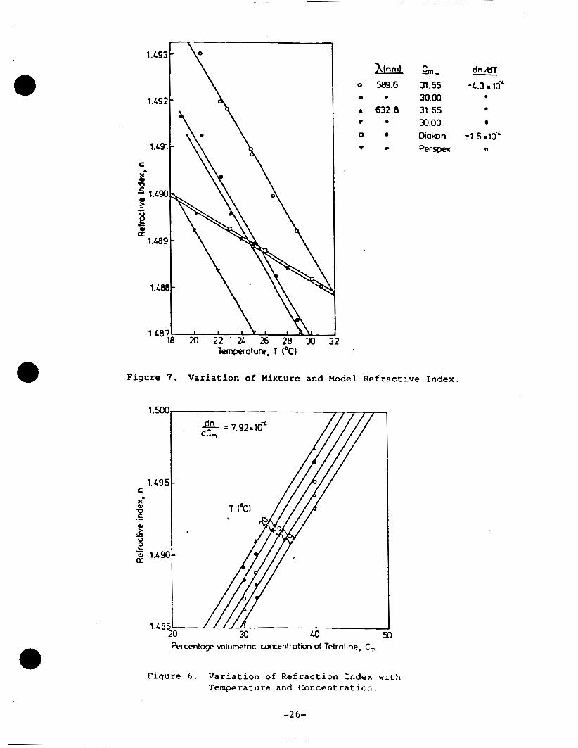
w i l l match t h a t of t he a c r y l i c . The ef . fect of mixture concent ra t ion (C,) i n
T e t r a l i n on the r e f r a c t i v e index as a func t ion of temperature is shown i n
Fig. 6 , which clearly i n d i c a t e s i t s s e n s i t i v i t y t o both parameters. Figure 7
shows the v a r i a t i o n of mixture r e f r a c t i v e index with temperature, as a func t ion
of T e t r a l i n concent ra t ion and l i g h t wavelength. This graph a l s o shows t h e
e f f e c t of temperature on the r e f r a c t i v e index of two common q u a l i t i e s of c l e a r
c a s t a c r y l i c (Perspex and Diakon). It can be concluded t h a t many combinations
of temperature and concent ra t ion w i l l achieve refractive-index-matching between
the two media. Figure 7 a l s o demonstrates t h a t t he matching temperature may
inc rease sharp ly by a small i nc rease i n T e t r a l i n concent ra t ion (7" C f o r 1.7%
i nc rease i n T e t r a l i n conten t ) . Since h igh temperatures w i l l shor ten t h e u s e f u l
l i f e of the t r anspa ren t model, t h e best p r a c t i c e is t o set the temperature
s l i g h t l y above ambient (e.g., 25" C) and a d j u s t t he conten t of T e t r a l i n t o
match the r e f r a c t i v e index of the acry l ic . 0
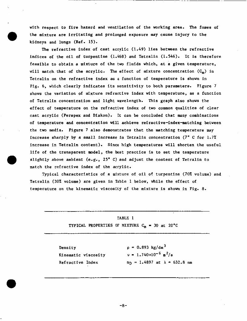
Typical c h a r a c t e r i s t i c s of a mixture of o i l of t u rpen t ine (70% volume) and
T e t r a l i n (30% volume) a r e given i n Table 1 below, while t he e f f e c t of
temperature on t h e kinematic v i scos i ty of t h e mixture i s shown i n Fig. 8 .
TABLE 1
TYPICAL PROPERTIES OF MIXTURE C, = 30 at 20°C
Dens i t y
Kinematic v i s c o s i t y
Ref rac t ive Index nD = 1.4897 a t A = 632.8 nm
p = 0.893 kg/dm3
v = 1 . 7 4 0 ~ 1 0 - ~ m 2 / s
-8-

THE LASER VELOCIMETER
A dual-beam, forward-scatter laser velocimeter was used for the present preliminary tests. A detailed description of the system is given in Ref. 16
and only a brief outline is given here. a rotating diffraction grating-based optical head on the transmission side and
integrated photomultiplier optical unit on the collection side. The signal processing system was based on a Doppler burst counter processor interfaced to a microcomputer for data acquisition and processing. Typical characteristics of the laser velocimeter are given in Table 2.
It consisted of a 5 mW &-Ne laser and
TABLE 2 CHARACTERISTICS OF THE LASER VELOCIMETER
Laser wavelength ~ 632.8 nm Beam intersection half angle 5.97 deg Length of measurement volume 780 w Diameter 80 IJm
Fringe spacing 3.04 pm
Frequency shift (variable) 0-7 MHz
The receiving optics of the system were suitable for off-axis light
collection which proved to be particularly useful for the present flow configuration in teras of reducing the effective dimensions of the measurement volume and improving the signal-to-noise ratio of the optical system.
PRELIMINARY TESTS
Three stages of preliminary tests were conducted prior to the final assembly of the experimental setup. The first two of these three preliminary tests were conducted as part of other programs (Refs. 9, 10, 11 and 13) and are included here for completeness in view of their support of the viability of the refractive-index-matching concept fo r the present application.
-9-

The f i r s t test is depic ted i n Fig. 9 and was designed t o examine the
a b i l i t y of t h e chosen mixture t o p e r f e c t l y match t h e r e f r a c t i v e index of t h e
a c r y l i c .
measured wi th bo th beams of t h e laser ve loc imeter c r o s s i n g a t r a n s p a r e n t
temperature c o n t r o l l e d tank containing the r e f r a c t i v e index f l u i d and t h r e e
p a i r s of c r o s s i n g rods.
The axial mean and turbulen t v e l o c i t y components of an a i r j e t were
Two sets of r e s u l t s are shown i n Fig. 10: one obta ined with the laser
beams pass ing through t h e rod bundle and one with t h e beams pass ing only
through the f l u i d . Both sets of results agree wi th in experimental accuracy,
sugges t ing t h a t n e i t h e r t h e p o s i t i o n nor t h e f r i n g e spac ing of t h e probe volume
were a l t e r e d when the a c r y l i c rods were i n the pathway of t h e beams. This tes t
proved t h a t t h e matching of t h e a c r y l i c material was f e a s i b l e with t h e chosen
mixture and allowed the f u r t h e r design of t he test rig.
The second test is i l l u s t r a t e d i n Fig. 11. The complete LOX post assembly
was immersed i n a temperature cont ro l led ba th of r e f r a c t i v e index f l u i d . The
laser beams of the ve loc imeter were made t o c r o s s t h e whole depth of t h e
assembly and t h e i r i n t e r s e c t i o n point was pro jec t ed wi th a microscope o b j e c t i v e
l e n s on to a screen. The a c t u a l c ross ing of t h e beams w a s t hen t e s t e d a t t h e
matching temperature and the q u a l i t y of t h e i n t e r f e r e n c e p a t t e r n was examined.
Both were found t o be accep tab le , i n d i c a t i n g t h a t t h e s u r f a c e q u a l i t y of t h e
rods w a s adequate t o allow accura t e measurements t o be obta ined i n t h e model.
Some sample measurements were also obtained i n s i d e t h e t ank t o prove t h i s
po in t .
The purpose of t h e t h i r d test was t o eva lua te t h e a b i l i t y of t h e system t o
main ta in cons tan t temperature a l l over the model space and t o allow the
matching of t h e r e f r a c t i v e index of the f l u i d under n e a r l y normal o p e r a t i n g
cond i t ions . It should be emphasized here t h a t temperature g r a d i e n t s i n s i d e a
model may be p re sen t , p a r t i c u l a r l y near t h e w a l l s and could o b s t r u c t t h e
near-wall measurements (Ref. 13). The des ign of the p re sen t model was such
t h a t , due t o t h e cons iderable th ickness of t h e o u t e r walls and t h e low
temperature of t he f l u i d , w a l l temperature g r a d i e n t s should be minimal. I n
a d d i t i o n , t h e s i z e of t h e rods and t h e i r arrangements i n s i d e t h e model should
be i d e a l f o r the uniform temperature d i s t r i b u t i o n i n s i d e the model.
During t h i s test , the o u t l e t of t he model was blocked with a f l a t p la te
wi th t h e temperature sensor posit ioned i n its cen te r . The f l u i d w a s then
c i r c u l a t e d , us ing one s i n g l e pump, en te r ing t h e model a t t h e oxygen-side and
-10-

e x i t i n g from the hydrogen-side t r ans fe r ducts . This opera t ion mode a l s o
e l imina ted t h e i n i t i a l l y observed ae ra t ion problems of t h e f l u i d .
flow cond i t ions , t he t i m e cons t an t s of t he e l e c t r o n i c temperature c o n t r o l l e r
were ad jus t ed t o keep t h e f l u i d temperature cons tan t w i th in 0.1" C.
matching of the r e f r a c t i v e index of the f l u i d was then performed us ing the
procedure descr ibed i n Refs. 7 and 8. A s i n g l e laser beam was passed through
the s o l i d boundary of t he model and projected on a screen , a few meters away.
The laser beam w a s then t r ave r sed ho r i zon ta l ly by a given amount so as t o c r o s s
the ou te r edge of t he curved boundary a t t he e x i t nozzle of the model. The
r e f r a c t e d laser beam w a s then observed, having moved s i g n i f i c a n t l y f u r t h e r .
The f l u i d temperature w a s k e p t constant a t 23.4" C and pure T e t r a l i n added t o
the c i r c u l a t i n g mixture u n t i l t he r e f r ac t ed beam r s tu rned t o i t s due pos i t i on .
A f i n e r adjustment of the mixture was a l s o performed by t r ave r s ing the laser
beam through t h e LOX post assembly and observ ing the excursion of t h e p ro jec t ed
beam on the screen. Small temperature adjustments f i n a l i z e d the matching
process .
Under t h e s e @ The
The p o s i t i v e outcome of a l l three tests confirmed the f e a s i b i l i t y of
ob ta in ing accu ra t e v e l o c i t y measurements i n t h e complex flow conf igu ra t ion of
t he model of the SSME Main I n j e c t o r Bowl, us ing the refractive-index-matching
technique. Some sample v e l o c i t y measurements i n t h i s conf igu ra t ion are
presented i n the fol lowing s e c t i o n and sugges t ions f o r f u r t h e r improvements of
the experimental system are made i n the l as t s e c t i o n of t h i s r epor t .
e
VELOCITY FIELD MEASUREMENTS
Mean and t u r b u l e n t component measurements were obtained i n s e v e r a l
l o c a t i o n s i n s i d e the model, configured as descr ibed i n the above t h i r d test .
The measurement l o c a t i o n s are indica teh by letters A-E i n Figs. 12-13. The axial v e l o c i t y d i s t r i b u t i o n at the e x i t of the 'oxygen' t r a n s f e r duc ts
( l o c a t i o n A-A) is shown i n Fig. 14. The v e l o c i t y p r o f i l e e x h i b i t s
c h a r a c t e r i s t i c s of f u l l y developed pipe f low with maximum v e l o c i t i e s of
1.9 ms" and measurements were obtained as c l o s e as 0.5 mm t o the pipe wall .
It should be noted t h a t during these measurements one of the laser beams was
c ross ing the curved o p t i c a l boundary of t h e race t r a c k a t incidence angles of
t he order of 70° and t h i s would have caused t o t a l r e f l e c t i o n of the beam ander
normal circumstances. However, the matching of t he r e f r a c t i v e i n d i c e s allowed
-1 1-

t h e s e measurements t o be obtained i n a s t r a igh t fo rward manner with r e l a t i v e
ease . Axial v e l o c i t y measurements were a l s o obta ined along a t r ave r se through
t h e LOX post assembly (B-B) and a t e shown by Fig. 13.
laser beams crossed a l a rge number of a c r y l i c rods under these condi t ions , t he
s i g n a l q u a l i t y was adequate f o r r e l i a b l e measurements t o be obtained.
l i m i t of ob ta in ing measurements a t t h e near-wall reg ion of the rods was found
t o be the l eng th of t he measurement volume so t h a t measurements were obta ined
as c lose as 300 pm t o the s u r f a c e s of the rods , when p a r t of the measurement
volume was loca ted i n s i d e the s o l i d boundary. In t h i s case, the c o l l e c t i o n
o p t i c s had t o be s l i g h t l y out of focus and the photomul t ip l ie r pinhole was
ad jus t ed t o 'see' t he f r e e p a r t of t h e l i g h t measurement volume. It was a t
these condi t ions t h a t off-axis l i g h t c o l l e c t i o n was found t o be p a r t i c u l a r l y
use fu l .
Although each of t h e
The
The a b i l i t y of the system t o measure very c l o s e t o the sur faces is
demonstrated i n Fig. 15 which presents a x i a l v e l o c i t y measurements between two
rods i n l o c a t i o n C. In t h i s case the diameter of the measurement volume w a s
t h e l i m i t i n g f a c t o r and s i n c e it was smaller than i t s l eng th (80 vs 780 pm),
al lowed measurements t o be obtained as c l o s e as 100 mn from the surface. These
r e s u l t s a l s o i l l u s t r a t e t h e complex na tu re of t h e wake of t h e rods and t h e h igh
turbulence i n t e n s i t y i n these regions.
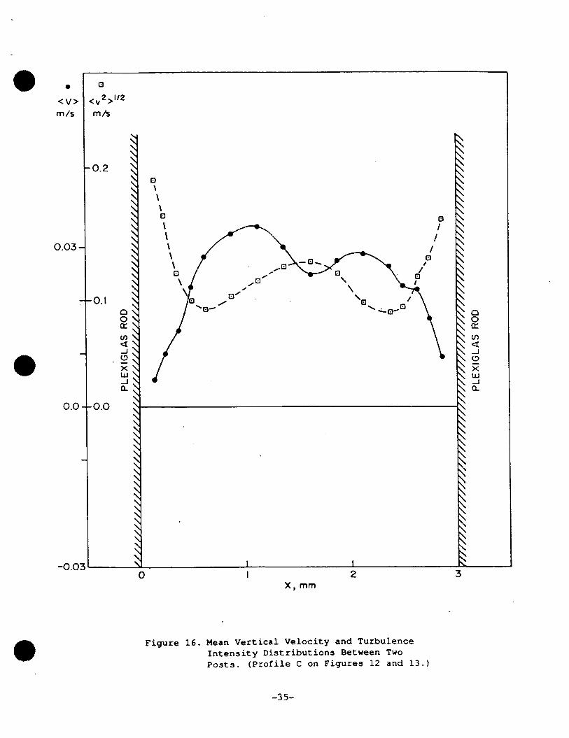
Figure 16 presen t s measurements ob ta ined aga in i n loca t ion C, but of t h e
v e r t i c a l ve loc i ty component. They were obta ined with the model opera t ing under
normal condi t ions (i.e. flow enter ing from a l l t r a n s f e r duc ts and e x i t i n g
through the nozzle) . Similar d e t a i l as t h a t of Fig. 15 could be obtained,
demonstrating t h e a b i l i t y t o measure two or thogonal v e l o c i t y components.
A test of the e f f e c t of f l u i d temperature on the measured ve loc i ty and
d a t a rate was a l s o conducted i n two l o c a t i o n s of t h e model, D and E, and t h e
r e s u l t s are shown i n Fig. 17. A t the f i r s t l o c a t i o n ( D ) , the axial component
was measured o u t s i d e the LOX post assembly f o r f l u i d temperatures ranging
between 21" and 23.5" C. The e f f e c t of r e f r a c t i v e index mis-match on the mean
v e l o c i t y and d a t a rate was found t o be small, but was l a r g e r on turbulence
i n t e n s i t y . This behavior was a t t r i b u t e d t o the f a c t t h a t the laser beams a t
t h i s point ( D ) only crossed t h e outer boundary of t h e race t rack .of the model;
a mis-match of the r e f r a c t i v e indices would only cause elongat ion of the
measurement volume and d i s t o r t i o n of t he f r i n g e p a t t e r n , thus sus t a in ing a h igh
d a t a r a t e and inc reas ing the a p p a r e n t tu rbulence i n t e n s i t y . e -12-

The test conducted a t po in t E of t he model w a s more seve re s ince , not only
t h e laser beams were c ross ing p a r t of t h e LOX pos t assembly, but t h e i r plane
was a l s o pos i t ioned a t an angle of 30' t o t h e ho r i zon ta l .
measure under t h e s e circumstances demonstrated t h e f e a s i b i l i t y of o b t a i n i n g
shea r as w e l l as normal stress measurements by r o t a t i n g the plane of t he laser
ve loc imeter by +45' and -45' (Ref. 17). The e f f e c t of temperature v a r i a t i o n on
t h e v e l o c i t y and da ta rate measurements a t t h i s po in t is a l s o shown i n Fig. 17
and i n d i c a t e s t h a t t h e r e f r a c t i v e index mis-match a f f e c t e d t h e d a t a rate as
w e l l as the mean and tu rbu len t ve loc i ty measurements due t o the r e s u l t i n g
pa r t i a l c ros s ing of t he laser beams and t h e simultaneous d i s t o r t i o n of t h e
range p a t t e r n on the measurements volume. It is shown t h a t a temperature
excurs ion of 0.7' C from t h e matching po in t may l ead t o 100% e r r o r i n mean
v e l o c i t y measurements.
The a b i l i t y t o
F i n a l l y , an a t t e m p t t o measure turbulence s p e c t r a a t two l o c a t i o n s i n t h e
model was made. This is an important c a p a b i l i t y of t h e sys t em i f vortex-
shedding c h a r a c t e r i s t i c s of t h e rods need t o be s tud ied . For t h i s tes t , a
frequency t r a c k e r and FFT ( f a s t Fourier transform) ana lyzer were used, although
t h e frequency counter system could be adapted t o perform t h e same ta sk , with
proper da t a a n a l y s i s software. The main l i m i t a t i o n i n t h i s case comes from the
v a l i d s i g n a l d a t a rate which, with the p re sen t c o n f i g u r a t i o n and without
a r t i f i c i a l seeding of the flow was of t he o rde r of 100 samples/s. The
turbulence s p e c t r a shown i n Fig. 18 may no t be a r e l i a b l e measurement of t h e
h igh f requencies . The a d d i t i o n of seeding par t ic les i n the flow, however,
would improve t h e i r r e l i a b i l i t y . It should a l s o be noted t h a t vor tex shedding
f r equenc ie s are expected t o be iii the lov frequency range, of the order of a
f e w Hertz, i n which case, t h e turbulence s p e c t r a measurements w i l l be easier t o
ob ta in .
The ques t ion of seeding particles is impor tan t , s i n c e t h e add i t ion of
commonly used l a t e x par t ic les i n the f l u i d is not d e s i r a b l e as they may a f f e c t
its p rope r t i e s . The choice of s o l i d , i n e r t p a r t i c l e s may be considered as a
b e t t e r s o l u t i o n provided t h a t t h e i r abras ive c h a r a c t e r i s t i c s can be t o l e r a t e d .
The use of aluminum oxide o r k a o l i n powder p a r t i c l e s would a l s o be under
c o n s i d e r a t i o n i n Phase 11.
-1 3-
CONCLUDING REMARKS
This r epor t has presented a study of t he f e a s i b i l i t y of applying
r e f r ac t ive - indexmatch ing and laser velocimetry methods for t h e d e t a i l e d
v e l o c i t y measurement of the flow f i e l d i n t h e complex geometry of a model of
t h e Main I n j e c t o r Bowl of t h e SSME.
revea led the following:
The pre l iminary tests and measurements
1. A f l u i d mixture c o n s i s t i n g of o i l of t u r p e n t i n e and tetrahydronaph-
tha l ene was found t o be s u i t a b l e f o r matching the r e f r a c t i v e index of
c l e a r cast a c r y l i c a t near ambient tempera tures and t o have e x c e l l e n t
rheo log ica l c h a r a c t e r i s t i c s .
The manufacture of a t r anspa ren t model of t h e SSME Main I n j e c t o r Bowl
i n clear cast a c r y l i c was f e a s i b l e and a tes t f a c i l i t y of t h e flow and
temperature c o n t r o l of ther r e f r a c t i v e index f l u i d was cons t ruc ted and
t e s t e d .
2.
3. Measurements of t h r e e ve loc i ty components and of t h e corresponding
normal and shear t u rbu len t stresses is poss ib l e i n most l o c a t i o n s of
t h e t r a n s p a r e n t model. The accuracy of t h e measurements is similar t o
t h a t of ord inary laser velocimetry provided t h a t t h e r e f r a c t i v e
i n d i c e s of t h e two media match c lose ly . Temperature c o n t r o l of t h e
f l u i d wi th in 0.10' C is necessary and can be obta ined i n the
experimental f a c i l i t y developed.
4. Near-wall v e l o c i t y f i e l d measurements are a l s o poss ib l e and are
l i m i t e d by t h e dimensions of the ve loc imeter ' s probe volume.
v e l o c i t y measurements as close as l O O u m t o the s i t i faces of the LGX
pos t s were shown t o be possible.
Re l i ab le
5 . The measurement of turbulence spectra i n the model was a l s o shown t o
be f e a s i b l e but l i m i t e d accuracy-was a t t a i n e d because of t h e a r r i v a l
rate of t he seeding p a r t i c l e s .
6. Severa l i s s u e s r equ i r ing f u r t h e r work were i d e n t i f i e d , mostly
regard ing t echn ica l a spec t s of t h e tes t f a c i l i t y . Those were the
following:
- Incompa t ib i l i t y between o rd ina ry pipe f i t t i n g s and working f l u i d .
- A r t i f i c i a l seeding of the flow i s requi red .
- Flu id a e r a t i o n problems may have t o be reconsidered.
-14-

- Data analysis software for turbulence spectra measurements with the
Doppler frequency counter needs to be developed.
Fine micropositioning of the laser velocimeter is required for the
near-wall measurements.
-
7 . Ref ractive-index-matching techniques are applicable to the study of
SSME and rocket-engine configurations, although there is a need to
quantify the similarity and measurement accuracy that can be attained.
ACKNOWLEDGEMENTS
The authors wish to thank Dr. H. McDonald and Mr. J.M. Nouri for their
helpful suggestions and assistance throughout this project.
-1 5-
REFERENCES
a 1.
2.
3.
4.
5 .
6.
7.
8.
9.
'10.
11.
12.
13.
Born, M. and Wolf, E.: P r inc ip l e s of OptAcs, Pergamon Pres s , 1970.
Dth Ed.,
R.P. C a r g i l l e Labora tor ies , Inc.: R e f r a c t i v e Index Liquids - Data Shee t , Cedar Grove, N J 07009.
Locke, J.: Improvements i n t h e Use of S i l i c o n e O i l s f o r t h e Determination of Glass Ref rac t ive Ind ices , J. of t h e Forensic Science Socie ty , Vol. 22, 257-262, 1982.
Durst , F., Keck, T. and Kleine, R.: Turbulence Q u a n t i t i e s and Reynolds S t r e s s i n Pipe Flow of Polymer Solu t ions , Proc. 6 th Symposium on Turbulence i n Liquids , Univ. Missouri-Rolla, 1979.
Edwards, R.V and Dybbs, A.: Refrac t ive Index Matching f o r Veloc i ty Measurements i n Complex Geometries, TSI Quar te r ly , Vol. X, I s sue . 4, 0ct.-Dec 1984.
Imper ia l Chemical I n d u s t r i e s PLC: Perspex Cell-Cast Acry l i c Sheet: P rope r t i e s and Fabr i ca t ion Techniques, Technical Serv ice Note PX127, 3rd Ed., 1981.
Horjay, M. and Leuckel, W.: LDA Measurements of Liquid Swirl Flow i n Converging Swir l Chambers with Tangential I n l e t s , Proc. 2nd I n t l . Symp. on Appl ica t ions f o r Laser Anemometry t o -Fluid Mechanics, Lisbon, 1984.
Nouri, J.M.: S ingle and Two-phase Flows i n Ducts and a S t i r r e d Reac tor , Ph.D. Thes is , Univ. of London, t o be submitted 1987.
Nouri, J.M., Whitelaw, J.H. and Yianneskis, M.: An Inves t iga t ion of Refractive-Index Matching of Continuous and Discontinuous Phases, Proc. 3rd I n t l . Symp. on Applications of Laser Anemometry t o F lu id Mechanics, Lisbon, 1986.
Yianneskis, M. and whitelaw, J.H.: Ve loc i ty Characteristics of Pipe and Jet Flows wi th High P a r t i c l e Concentration, Imperial College, Mech. Eng. Dept., Report FS/83/22, 1983.
Nouri, J.M: Turbulent Flow of Moderately Dense P a r t i c l e s Suspensions i n a S t i r r e d Reactor, Imperial College, Mech. Eng. Dept., Report FS/87/05, 1987.
Taylor, A.M.K.P. and Whitelaw, J.H.: Veloc i ty Characteristics i n t h e Turbulent Near Wakes of Confined Axisymmetric Bluff Bodies, J. Fluid Mech., Vol. 139, pp. 391-416, 1984.
Yianneskis, M., Tindal, M.J. and Pau l , G.R.: The Application of Laser Anemometry t o the Study of Flows I n s i d e Diesel Engine I n l e t . P o r t s , Proc. 3rd I n t l Symp on Appl ica t ions of Laser Anemometry t o Fluid Mechanics, Lisbon, 1986.
-16-

REFERENCES (Continued)
14. Elphick, I.G., Martin, W.W. and Curr ie , I.G.: Appl i ca t ion of LDA t o High Reynolds Number Cross Flow, Proc. 1st I n t l . Symp. on Appl ica t ions of Laser Anemometry t o F lu id Mechanics, Lisbon 1982.
15. Sax, N.I.: Dangerous P rope r t i e s of I n d u s t r i a l Materials, van Nostrand Rheinhold, New York, 1979, pp. 1017 and 1075.
16. Vaf id i s , C: FS/1 Laser Doppler Anemometry - I n s t r u c t i o n Manual, Imper ia l College, Mech. Eng. Dept., Report FS/86/49, 1986.
17. Durst, F., Melling, A. and Whitelaw, J.H.: P r i n c i p l e s and Practice of Laser-Doppler Anemometry, 2nd Ed., Academic Press, 1981.
-17-

-18-
& 0 JJ 0 d) n c n
-19-
Q cv
-23-

-21-

n P)
-0 X
X s
0 z
P) U 0 L:
-22-
.IC MODEL
LOXSIDE INFLOW
Figure 4. 36% Model Configuration.
-2 3-

-24-

-2 5-
~
Y c 4 CI
Q) P (II Lc 0 JJ v)
4 0 &
Tempe,mture, T (OC)
dn MT Cm-
0 569.6 3 .65 -L.3 m 10' 0 .I 30.00 a
A 632.8 31.65 v 30.00 0 Diabn -1.5 MI^‘ v 11 Perspex II
I
Figure 7 . Variat ion of Mixture and Model Refrac t ive Index.
1
1. C - X 0,
P
ti .', 1.L90-
Q, > .-
a
Percentoge dumetric concentration of Tetraline, C,,,
Figure 6 . Variat ion of Refract ion Index w i t h Temperature and Concentration.
-2 6-

1.80
X c
'v1 cu
1.70 . >
1.6C
1 .SO Temperature, T ("C]
Figure 8. Mixture Kinematic Viscosity.
v 30.00
0 40.00 * 31.65
-27-

c c, -d 3 Y c cd c, c:
0 u
B d
-28-

1 ..o
O . 4
0.6
WC 0 . 4
0.2
0.0
1.0
0.8
0.6
O / O C
0.4
0.2
0.0
2=3. ODe
6 0 0 : u/Uc Without rod bundle
v : U/Uc With rod bundle on the way of beans
z e: u/oc I/ // /I
v : u/uc N /I /I U b I f +
I/
8-v -v-v-v-g-v, 6’ 8 Z=O. 07De I
0 I I F b I\
l a 1,. 0
-0.1
-0.08
-0.06 z u/Oc
-0. c4
-0.02
-0.0
-0.1
-0.08
-0.06
-0 .04
-0.02
-0.0
I I I I I I I I 2.0 1.5 1.0 0.5 0.0 -0.5 -1.0 -1.5
Figure 1 0 . Mean Veloc i ty and Turbulence I n t e n s i t y i n a Rod Bundle.
-2 9-

Y H e o t e r
1-
cooling coil
31 LDA
Figure 11. 36% Model Immersed i n a Mixture Bath.
-30-

0 4
-31-

-32-

0”””
33mm,//// /
O”’/’/
33mm 4
B O
7
B lm
Figure 1 4 . Mean V e l o c i t y and Turbulence I n t e n s i t y D i s t r i b u t i o n at t h e Exi t of t h e I n l e t Ducts .
-33-

0
<lJ> m/r
0.03.
0.0
-0.0:
Q
c "2, ''2
\
m /s
0.2
,0.1
a g\
0.0
0 I 2 X, mm
3
Figure 15 . Mean Horizontal V e l o c i t y and Turbulence I n t e n s i t y D i s t r i b u t i o n s Between Two P o s t s . ( P r o f i l e C on Figures 12 and 1 3 . )
-34-
< V > m /s
0.03 -
0.0
-0.0:
m/s
- 0.2
-0.1
-0.0
0 0 U v)
J (3
X W J a
a -
0
<"*>"2
0 \ \ \ B B \ I \
X , mm
Figure 1 6 . Mean Vert i ca l V e l o c i t y and Turbulence I n t e n s i t y Di s tr ibut ions Between T w o P o s t s . ( P r o f i l e C on Figures 12 and 13.)
-35-

0
<U> m/s
1.95
0 t-
0 a z 1.90
1.85
0.4
0.3 W I- z a 5 0.2
0.1
B C" * >1'*
m/s
.I40 0 0
+ +
.I35
B .I30
0.4
,0.3
0.2
,0.1
0 + + 0 B 0
8 0 + + +
+
0 +
0
B B
8
0
+ Sampling
Time (Second8 for
1000 sampler)
35.
30.
25.
B 0
B B
+ 3 0
0
+ + + 0
0
120.
too
80
60
1 1 I
22 23 24 25 t I
MATCH1 NG TEMPERATURE
TEMPERATURE ("C)
Figure 17. Mean Horizontal Velocity, Turbulence Intensity, and Sampling Time vs. Temperature. Results Obtained at Points D and E as Indicated.
-36-

.
f U 0 1 a U 01 4 E I4
w 0
U 4 X w
2 A
4
w C 0 4 4J 4 0 0 84 Ll 4
z"
z a"
aJ 4
a m
a &
c H
A
0
w C 0 4 U
0 0 84 Ll a Q z Q 4 a C 5
a
m
4 tc c n
-37-
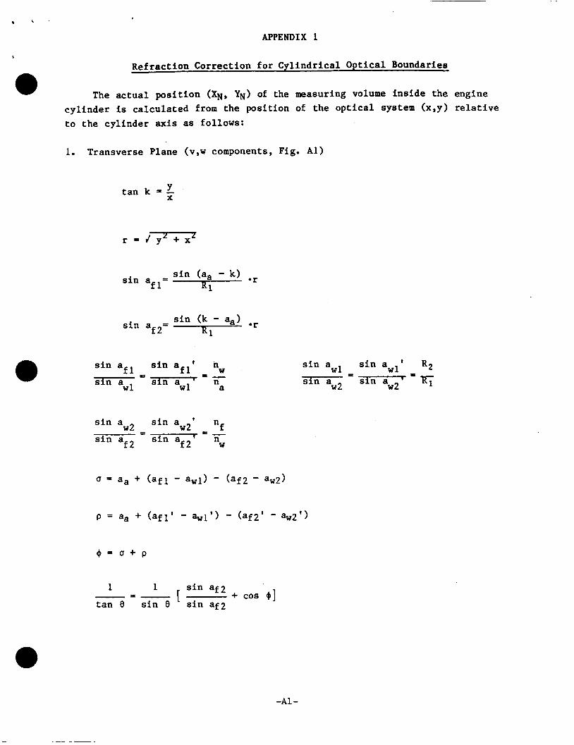
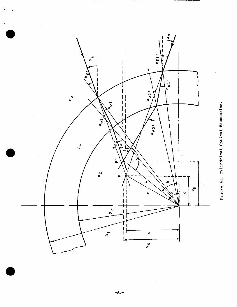
APPENDIX 1
. Ref rac t ion Correc t ion f o r Cy l ind r i ca l Op t i ca l Boundaries
The actual pos i t i on (XN, YN) of the measuring volume i n s i d e the engine c y l i n d e r is ca lcu la t ed from the posi t ion of t he o p t i c a l system (x,y) relative t o the cy l inder axis as fol lows:
a
Y t an k = - X
s i n (k - aa) s i n a f2= *r R1
W s i n a ' n f l
n w l a - - P
f l
w l
s i n a s i n a s i n a '
s i n a s i n awl' Rp
w 2 w2 s i n a =7 w1 si
s i n a '
f
f 2 W
s i n aw2' n n s i n a ' = = - w 2
f 2
s i n a
s i n a
+ cos + I 1 1
t a n 8 s i n 8 -3-
-A1 -

. '
1. Transverse Plane Continued
sin af2'
sin 0 r' = R p
XN = r' *COS k'
From the above relations the actual position of the measuring volume
(XN, m), the actual beam intersection angle (0) and the angle of the sensitivity vector (a, p) can be calculated.
-A2 -
0) Q) 4 Lc 4 a c =I 0 rn 4 4 V 4 c, a 0

2. Plane P a r a l l e l t o the Axis (U component, Fig. A2)
t a n a f l = Y K l
f s i n aw2 n = -
s i n a f 2 "w
( t ' = Rp - R p f o r y = 0)
A = v' n f Z 2 - - s i n a, "a
B = J nwz 2 - - s i n a, "a
A de = (1 -F) (t' - t )
-A4 -

I ' . I
t
Figure A2. Refrac t ive Index P o s i t i o n a l Correct ions .
4 5 -