s. rdso remarks final draft technical on the comments ... document... · butt welding plant...
TRANSCRIPT
Page 1 of 49
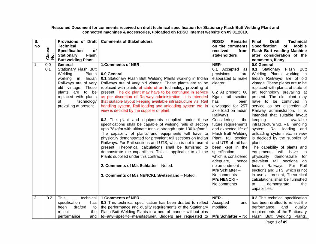
Reasoned Document for comments received on draft technical specification for Stationary Flash Butt Welding Plant and connected machines & accessories, uploaded on RDSO internet website on 09.01.2019.
S. No
Cla
use
No.
Provisions of Draft Technical Specification of Stationary Flash Butt welding Plant
Comments of Stakeholders RDSO Remarks on the comments received from stakeholders
Final Draft Technical Specification of Mobile Flash Butt welding Machine after consideration of the comments, if any.
1. 0.0 0.1
General Stationary Flash Butt Welding Plants working in Indian Railways are of very old vintage. These plants are to be replaced with plants of technology prevailing at present
1.Comments of NER – 0.0 General 0.1 Stationary Flash Butt Welding Plants working in Indian Railways are of very old vintage. These plants are to be replaced with plants of state of art technology prevailing at present. The old plant may have to be continued in service as per discretion of Railway administration. It is intended that suitable layout keeping available infrastructure viz. Rail handling system, Rail loading and unloading system etc. in view is decided by the supplier of plant. 0.2 The plant and equipments supplied under these specifications shall be capable of welding rails of section upto 78kg/m with ultimate tensile strength upto 130 kg/mm2. The capability of plants and equipments will have to physically demonstrated for prevalent rail sections on Indian Railways. For Rail sections and UTS, which is not in use at present, Theoretical calculations shall be furnished to demonstrate the capabilities. This is applicable to all the Plants supplied under this contract. 2. Comments of M/s Schlatter – Noted.
3. Comments of M/s NENCKI, Switzerland – Noted.
NER- 0.1 Accepted as provisions are elaborated to make clearer. 0.2 At present, 60 Kg/m rail section has been envisaged for 25T axle load on Indian Railways. Considering the future requirements and expected life of Flash Butt Welding Plant, rail section and UTS of rail has been kept in the specification; which is considered adequate, hence no amendment . M/s Schlatter – No comments M/s NENCKI - No comments
0.0 General 0.1 Stationary Flash Butt Welding Plants working in Indian Railways are of old vintage. These plants are to be replaced with plants of state of art technology prevailing at present. The old plant may have to be continued in service as per discretion of Railway administration. It is intended that suitable layout keeping available infrastructure viz. Rail handling system, Rail loading and unloading system etc. in view is decided by the supplier of plant. The capability of plants and equipments will have to physically demonstrate for prevalent rail sections on Indian Railways. For Rail sections and UTS, which is not in use at present, Theoretical calculations shall be furnished to demonstrate the capabilities.
2. 0.2 This technical specification has been drafted to reflect the performance and
1.Comments of NER - 0.3 This technical specification has been drafted to reflect the performance and quality requirements of the Stationary Flash Butt Welding Plants in a neutral manner without bias to any specific manufacturer. Bidders are requested to
NER - Accepted and modified. M/s Schlatter – No
0.2 This technical specification has been drafted to reflect the performance and quality requirements of the Stationary Flash Butt Welding Plants.
Page 2 of 49
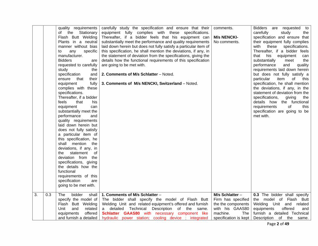
quality requirements of the Stationary Flash Butt Welding Plants in a neutral manner without bias to any specific manufacturer. Bidders are requested to carefully study the specification and ensure that their equipment fully complies with these specifications. Thereafter, if a bidder feels that his equipment can substantially meet the performance and quality requirements laid down herein but does not fully satisfy a particular item of this specification, he shall mention the deviations, if any, in the statement of deviation from the specifications, giving the details how the functional requirements of this specification are going to be met with.
carefully study the specification and ensure that their equipment fully complies with these specifications. Thereafter, if a bidder feels that his equipment can substantially meet the performance and quality requirements laid down herein but does not fully satisfy a particular item of this specification, he shall mention the deviations, if any, in the statement of deviation from the specifications, giving the details how the functional requirements of this specification are going to be met with. 2. Comments of M/s Schlatter – Noted. 3. Comments of M/s NENCKI, Switzerland – Noted.
comments. M/s NENCKI- No comments.
Bidders are requested to carefully study the specification and ensure that their equipment fully complies with these specifications. Thereafter, if a bidder feels that his equipment can substantially meet the performance and quality requirements laid down herein but does not fully satisfy a particular item of this specification, he shall mention the deviations, if any, in the statement of deviation from the specifications, giving the details how the functional requirements of this specification are going to be met with.
3. 0.3 The bidder shall specify the model of Flash Butt Welding Unit and related equipments offered and furnish a detailed
1. Comments of M/s Schlatter – The bidder shall specify the model of Flash Butt Welding Unit and related equipment’s offered and furnish a detailed Technical Description of the same. Schlatter GAAS80 with necessary component like hydraulic power station; cooling device ; integrated
M/s Schlatter – Firm has specified the the components with his GAAS80 machine. The specification is kept
0.3 The bidder shall specify the model of Flash Butt Welding Unit and related equipments offered and furnish a detailed Technical Description of the same.

Page 3 of 49
Technical Description of the same. System/sub-systems and working mechanisms of the machine shall be described in the “Technical Description” in detail along with the sketches to show the manner in which the requirements of the specifications are accomplished by the offered model of FBW machine.
stripping device and weld processing system and Weld Analyzer System for quality control and storage data base. System/sub-systems and working mechanisms of the machine shall be described in the “Technical Description” in detail along with the sketches to show the manner in which the requirements of the specifications are accomplished by the offered model of FBW machine. 2. Comments of M/s NENCKI, Switzerland – Noted. But NENCKI is not the principal manufacturer of Welding Machine. However, with the expertise from Projects like Bhilai Steel Plant and Setting up of New FBWP at Sabarmati, NENCKI is able to build the specifications of a Welding Machine too.
generic. Hence, suggested specification for a particular model of machine/firm is not accepted. M/s NENCKI – Comments are informative only.
System/sub-systems and working mechanisms of the machine shall be described in the “Technical Description” in detail along with the sketches to show the manner in which the requirements of the specifications are accomplished by the offered model of FBW machine.
4. 0.4 The tenderer shall furnish video compact disc showing the working of Machine in real time under field conditions. Photographs of the machines offered and technical literature shall also be enclosed with the offer. The photographs shall also show close-ups of various working assemblies/systems and the full Plant.
1.Comments of NER - 0.5 The tenderer shall furnish video compact disc showing the working of Machine in real time under field conditions. In case, the tenderer intends to offer the improved version of Automatic Flash Butt Welding machine for welding of rails, for which video is not available, he can submit the video of his existing working plant with description of changes proposed and a walk through 3-D simulation model of proposed plant. Photographs of the machines offered and technical literature shall also be enclosed with the offer. The photographs shall also show close-ups of various working assemblies/systems and the full Plant. 2. Comments of M/s Schlatter – The tenderer shall furnish video compact disc showing the working of Machine in real time under field conditions. Photographs of the machines offered and technical literature shall also be enclosed with the offer. The photographs shall also show close-ups of various working assemblies/systems and the full Plant. Presentation material included. Available videos CD will be submitted along with tender documents. 3. Comments of M/s NENCKI, Switzerland – Noted Technical description, Photographs and videos of the individual working machines (Grinding, Straightening,
NER – Accepted as provisions are elaborated to make clearer . M/s Schlatter – Comments are informative only. M/s NENCKI – Comments are Informative only.
0.4 The tenderer shall furnish video compact disc showing the working of Machine in real time under field conditions. In case, the tenderer intends to offer the improved version of Automatic Flash Butt Welding machine for welding of rails, for which video is not available, he can submit the video of his existing working plant with description of changes proposed and a walk through 3-D simulation model of proposed plant. Photographs of the machines offered and technical literature shall also be enclosed with the offer. The photographs shall also show close-ups of various working assemblies/systems and the full Plant.
Page 4 of 49
Brushing, Test press) are available and if required can be submitted with the offer.
5. 0.5 All machines including Flash Butt welding machine should be well synchronized, durable, easy to maintain and of robust design. Machines should be able to coup up the forces coming during the operation.
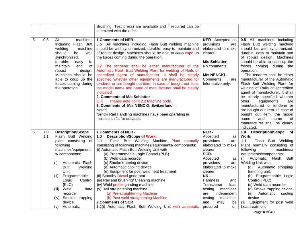
1.Comments of NER – 0.6 All machines including Flash Butt welding machine should be well synchronized, durable, easy to maintain and of robust design. Machines should be able to coup cope up the forces coming during the operation. 0.7 The tenderer shall be either manufacturer of the Automatic Flash Butt Welding Plant for welding of Rails or accredited agent of manufacturer. It shall be clearly specified whether other equipments are manufactured for tenderer or are bought out item. In case of bought out item, the model name and name of manufacturer shall be clearly indicated. 2. Comments of M/s Schlatter – O.K Please note point 2.2 Machine body. 3. Comments of M/s NENCKI, Switzerland – Noted Nencki Rail Handling machines have been operating in multiple shifts for decades
NER- Accepted as provisions are elaborated to make clearer M/s Schlatter – No comments. M/s NENCKI – Comments are Informative only.
0.5 All machines including Flash Butt welding machine should be well synchronized, durable, easy to maintain and of robust design. Machines should be able to cope up the forces coming during the operation. The tenderer shall be either manufacturer of the Automatic Flash Butt Welding Plant for welding of Rails or accredited agent of manufacturer. It shall be clearly specified whether other equipments are manufactured for tenderer or are bought out item. In case of bought out item, the model name and name of manufacturer shall be clearly indicated.
6. 1.0 1.1
Description/Scope Flash Butt Welding plant consisting of following machines/equipments/ components:
(i) Automatic Flash
Butt Welding Unit.
(ii) Programmable Logic Control (PLC)
(iii) Weld data recorder
(iv) Smoke trapping device
(v) Automatic
1.Comments of NER - 1.0 Description/Scope of Work: 1.1 Flash Butt Welding Machine Plant normally consisting of following machines/equipments/ components: (i) Automatic Flash Butt Welding Unit with
(a) Programmable Logic Control (PLC) (b) Weld data recorder (c) Smoke trapping device (d) Automatic cooling device (e) Equipment for post weld heat treatment
(ii) Standby Diesel generator (iii) Rail end brushing/ Cleaning machine (iv) Weld profile grinding machine (v) Rail straightening machine
(a) Pre-straightening Machine (b) Post weld straightening Machine
2.Comments of SCR 1.1(i) Automatic Flash Butt Welding Unit with automatic
NER - Accepted as provisions are elaborated to make clearer SCR- Accepted as provisions are elaborated to make clearer NR – Hardness and Transverse load testing machines are independent testing machines and may be procured on
1.0 Description/Scope of Work: 1.1 Flash Butt Welding Plant normally consisting of following machines/ equipments/components: (i) Automatic Flash Butt Welding Unit with
(a) Automatic stripping/ trimming unit. (b) Programmable Logic Control (PLC) (c) Weld data recorder (d) Smoke trapping device (e) Automatic cooling device
(ii) Equipment for post weld heat treatment

Page 5 of 49
cooling device (vi) Equipment for
post weld heat treatment
(vii) Standby generator
(viii) Rail end brushing machine
(ix) Weld grinding machine
(x) Rail straightening machine
stripping/ trimming unit. 1.1(ix) Fully automatic Weld grinding machine 1.1(x) Rail Pre-straightening machine & Post weld straightening machine 1.1 (xi) Automatic weld identification number punching machine 3. Comments of NR – Hardness and Transverse load testing machine should also be added. Capacity of transverse load testing machine and straightening press should also be compatible to heaviest section to be welded by welding machine in future. 4.Comments of M/s Mechelonic Semi-automatic profile grinding machine with manual grinding support is preferred as a automatic machine will take too long time for grinding, reducing production. 5.Comments of M/s Schlatter –
(i) Automatic Flash Butt Welding Unit
Subject of supply
(ii) Programmable Logic Control (PLC)
Siemens S700 machine control system and digital Weld processing System SWEP (programmable by weld Studio Programme
(iii) Weld data recorder
Schlatter WeldAnalyzer System
(iv) Smoke trapping device
Only the smoke extraction hood. Extraction device is part of the project scope of Maco Corporation.
(v) Automatic cooling device
Belongs to the scope of delivery point. Will be supplied as attachment
(vi) Equipment for post weld heat treatment
After weld -treatment not integrated in the FBW machine; separate air cooling device type Voest Alpine and associated
requirement basis, hence not required in this specification. Capacity of straightening machines is already mentioned at Clause 11. M/s Mechelonic – Not accepted as manual operation will give less accurate results. M/s Schlatter – Comments are Informative only. SR – Such measurement in welding line is not required hence not considered. M/s NENCKI – Comments are Informative only.
(iii) Standby Diesel generator (iv) Rail end brushing/ Cleaning machine (v) Fully automatic Weld profile grinding machine (vi) Rail straightening machine
(a) Pre-straightening Machine (b) Post weld straightening Machine
(vii) Automatic punching machine capable for punching weld identification number as per Para 9 of the Manual for Flash Butt Welding of Rails-Revised 2012. All above plant and equipments shall be capable of welding/ handling rails of section upto 68kg/m with ultimate tensile strength upto 130 kg/mm2.

Page 6 of 49
compressor is supplied as a separate part and must be used / operated manually. Standard machine so far supplied, no customer has demanded this provision. On specific requirement, provision could be made as per customers requirement.
(vii) Standby generator
not scope of supply by Schlatter. Part of project supply of Maco Corporation.
(viii) Rail end brushing machine
not scope of supply by Schlatter. Part of project supply of Maco Corporation.
(ix) Weld grinding machine
not scope of supply by Schlatter. Part of project supply of Maco Corporation.
(x) Rail straightening machine
not scope of supply by Schlatter. Part of project supply of Maco Corporation.
6.Comments of SR – Description/Scope shall include the following additional features: Digital Measuring Device for Rail Head Width and Height. Description/Scope shall include the measurement on head width or height of the rail etc. for selection or rejection of rail ends. One equipment for measurement shall be included under Para1.1. 7. Comments of M/s NENCKI, Switzerland – ii, v, vi, viii, ix and x are in the scope of Nencki for respective Machines. Rest is part of Flash Butt Welding Machine manufacturer.

Page 7 of 49
7. 1.2 Specification also covers installation of the plant, Training of the staff, Layout, Foundation of the machines, Instruction manuals, Inspection, Additional information, Equipment Environment, Warranty, etc.
1.Comments of NER – 1.2 All above plant and equipments shall be capable of welding rails of section upto 78kg/m with ultimate tensile strength upto 130 kg/mm2. 1.3 This specification broadly covers the Working Mechanism & Functional Requirements. The scope of work under this Specification also covers installation of the plant, Training of the staff, Layout, Foundation of the machines, Instruction manuals, Inspection, Additional information, Equipment Environment, Warranty, etc. 2.Comments of SCR - Specification also covers installation of the plant, commissioning of the plant including standardization of weld parameters by RDSO, Training of the staff, Layout, Foundation of the machines, Instruction manuals, Inspection, Additional information, Equipment Environment, Warranty, etc. 3. Comments of M/s Schlatter – Maco Corporation (India) Private Limited having adequate experience in setting up of FBW plants (latest being SAIL Bhilai Long Rail Welding Line – 02 Numbers), will do the installations, commissioning, AMC as well as provide all the support mentioned above. 4. Comments of M/s NENCKI, Switzerland – Noted
NER- 1.2 Provisions covered under clause 0.1 1.3 Accepted as provisions are elaborated to make clearer. SCR – Standardization of welding parameters by RDSO already mentioned in Manual for FB welding of rails-2012. Hence not considered. M/s Schlatter – Comments are Informative only. M/s NENCKI- No comments.
1.2 This specification broadly covers the Working Mechanism & Functional Requirements. The scope of work under this specification also covers installation of the plant, Training of the staff, Layout, Foundation of the machines, Instruction manuals, Inspection, Additional information, Equipment Environment, Warranty, Annual Maintenance Contract (AMC), etc.
8. 2.0 Working Mechanism & Functional Requirements:
1.Comments of NER – 2.0 Automatic Flash Butt Welding Machine: 2.1 General: Automatic Flash Butt Welding machine complete with integral upset removal device, automatic rail alignment crown adjusting and de-twist unit, power transformers and 02 years maintenance spares for welding rails up to 78 Kg/m (including special high wear resistant steel rails having tensile strength up to 130 Kg/mm²).
NER – 2.0 Considered. 2.1 Not accepted as provisions have already given in subsequent clauses.
2.0 Automatic Flash Butt Welding Machine:
9. 2.1 Weldability and range of application : The FBW Machine should be designed
1.Comments of NER- 2.2 Weldability and Range of application: The FBW Machine should be designed for welding rails up to 78 Kg/m having ultimate tensile strength up to 130 Kg/mm².
NER- Accepted except rail section 78 Kg/m and modified as provisions are
2.1 Weldability and range of application : The FBW Machine should be designed for welding rails up to 68 Kg/m having ultimate

Page 8 of 49
to weld new rails/ released but serviceable rails of various sections and metallurgies specified in Indian Railway’s Standard Specification for Flat Bottom Rails(IRS-T-12-2009) with up to date Addendum and Corrigendum slips (hereinafter called Specification of Rails) viz. 52/60/68Kg/m of grades 880(C-Mn, Cu-Mo, Ni-Cr-Cu, Niobium, Vanadium), 1080(HH, Cr). Plant would also be capable of welding of 60/68 Kg/m rails having mechanical & chemical properties of R350HT of BS EN 13674-1:2011+A1:2017.
The plant shall be capable to weld new rails/ released but serviceable rails of various sections and metallurgies specified in Indian Railway’s Standard Specification for Flat Bottom Rails (IRS-T-12-2009) with up to date Addendum and Corrigendum slips (hereinafter called Specification of Rails) viz. 52/60/68Kg/m of grades 880 (C-Mn, Cu-Mo, Ni-Cr-Cu, Niobium, Vanadium), 1080(HH, Cr). Plant would also be capable of welding of 60/68 Kg/m rails having mechanical & chemical properties of R350HT of BS EN 13674-1:2011+A1:2017. The machine should incorporate special post heat treatment facilities necessary to ensure quality welding results on special grade steels. The machine should have facility for traversing by atleast 500mm to facilitate central positioning of the ends of long welded rails 2.Comments of SCR- Cr may be written as Chromium 3. Comments of NR - Plant should be capable to weld rails upto 75 Kg/m and 12000 sqmm area. 4.Comments of M/s Schlatter - Standard by Schlatter 5.Comments of SR – Additional Para to be included as below: The Flash Butt welding Machine should be capable for welding of new rails/released serviceable rails of sectional area upto 12,000 Sq.mm. The recommended butting pressure for different types of rails are included below: 72 UTS Rails: 5 Kg/Sq.mm on cross sectional area. 90 UTS & HH Rails: 6 Kg/Sq.mm. 110 UTS Rails: 7 Kg/Sq.mm. 6. Comments of M/s NENCKI, Switzerland – Not applicable for Nencki. Part of Flash Butt Welding manufacturer
elaborated to make clearer. The post weld heat treatment facility is covered in clause 7.0. SCR- Abbreviation of elements are well known, hence full name is not required. NR – At present, 60 Kg/m rail section has been envisaged for 25T axle load on Indian Railways. Considering the future requirements and expected life of Flash Butt Welding Plant, rail section and UTS of rail has been kept in the specification; which is considered adequate, hence no amendment . M/s Schlatter - No comments SR – Rail sections specified in Indian Railway’s Standard Specification for Flat Bottom Rails(IRS-T-12-2009) have been incorporated in the
tensile strength up to 130 Kg/mm². The plant shall be capable to weld new rails/ released but serviceable rails of various sections and metallurgies specified in Indian Railway’s Standard Specification for Flat Bottom Rails(IRS-T-12-2009) with up to date Addendum and Corrigendum slips (hereinafter called Specification of Rails) viz. 52/60/68Kg/m of grades 880(C-Mn, Cu-Mo, Ni-Cr-Cu, Niobium, Vanadium), 1080(HH, Cr). Plant would also be capable of welding of 60/68 Kg/m rails having mechanical & chemical properties of R350HT of BS EN 13674-1:2011+A1:2017. The machine should have facility for traversing by at least 500mm to facilitate central positioning of the ends of long welded rails.

Page 9 of 49
specification. M/s NENCKI – Comments are Informative only.
10. 2.2 Machine Body : The Machine body should be preferably of a frame type construction capable of taking clamping and upset force to their axes of action. The machine frame assembly should be sturdy, all welded steel fabrication suitably braced and stiffened at points of stresses to minimize deflection and thermally stress relieved. The machine frame top should have a single continuous beam structure to minimize welded joints, so that deflection/ distortion/ cracks may be avoided. The weld zone should be fully covered with spatter guards to trap the flash and a fume extractor to be provided to exhaust this chamber. Guides should be provided at entry, and within the machine, to enable free passage for rails
1.Comments of NER - 2.3 Machine Body: The Machine body should be preferably of a frame type construction capable of taking clamping and upset force to their axes of action. The machine frame should have large openings in front of the welder to facilitate quick removal and replacement of welder dies and clamps and to provide maximum visibility for operation and maintenance. The machine frame assembly should be sturdy, all welded steel fabrication suitably braced and stiffened at points of stresses to minimize deflection and thermally stress relieved. The machine frame top should have a single continuous beam structure to minimize welded joints, so that deflection/ distortion/ cracks may be avoided. The weld zone should be fully covered with spatter guards to trap the flash and a fume extractor to be provided to exhaust this chamber. Guides should be provided at entry, and within the machine, to enable free passage for rails during entry and transport. The welding standard followed for manufacturing of machine should be to ISO:3834, EN:15085 or any other equivalent standard for welding railway vehicles and components. The manufacturer should specify the standard followed and certify that it meets the welding standard mentioned above. 2. Comments of M/s NENCKI, Switzerland – Not applicable for Nencki Machines. Part of Flash Butt Welding manufacturer In general: Our machines are produced according to the standard ISO 3834. For us it would also possible to manufacture the steel structures according to the EN 15085, since we are a EN 15085-certified company. A production according to EN 15085 is connected with additional costs and is not our basic standard.
NER – Modification accepted to facilitate welder for quick replacement of dies/electrode and to provide maximum visibility for operation and maintenance. M/s NENCKI – Comments are Informative only.
2.2 Machine Body: The Machine body should be preferably of a frame type construction capable of taking clamping and upset force to their axes of action. The machine frame should have large openings in front of the welder to facilitate quick removal and replacement of welder dies and clamps and to provide maximum visibility for operation and maintenance. The machine frame assembly should be sturdy, all welded steel fabrication suitably braced and stiffened at points of stresses to minimize deflection and thermally stress relieved. The machine frame top should have a single continuous beam structure to minimize welded joints, so that deflection/ distortion/ cracks may be avoided. The weld zone should be fully covered with spatter guards to trap the flash and a fume extractor to be provided to exhaust this chamber. Guides should be provided at entry, and within the machine, to enable free passage for rails during entry and transport. The welding standard followed for manufacturing of machine should be to ISO:3834,

Page 10 of 49
during entry and transport. The welding standard followed for manufacturing of machine should be to ISO:3834, EN:15085 or any other equivalent standard for welding railway vehicles and components. The manufacturer should specify the standard followed and certify that it meets the welding standard mentioned above.
EN:15085 or any other equivalent standard for welding railway vehicles and components. The manufacturer should specify the standard followed and certify that it meets the welding standard mentioned above.
11. 2.3 Production Capacity: The hourly output in terms of number of welded joints should be more than 20 in continuous rail panels including all activities from Pre-Straightening of rail ends to Post Straightening of produced welded joints. The plant should be capable of welding 260m long rail panels by continuous welding of 13/26/65m rail lengths. The actual welding cycle (insertion of rails, clamping and aligning rail ends, matching
1.Comments of NER 2.4 Production Capacity: The hourly output in terms of number of welded joints should be more than 20 for 60 kg 90UTS rails in continuous rail panels including all activities from Pre-Straightening of rail ends to Post Straightening of produced welded joints. The plant should be capable of welding 260m long rail panels by continuous welding of 13/26/65m rail lengths. The actual welding cycle (insertion of rails, clamping and aligning rail ends, matching rail ends through power adjustment, welding cycle, stripping of upset, unclamping and resetting of machine) should not take more than 120 seconds for 60kg/m 90 UTS Rails. The time in seconds for various operations per joint like positioning of welding machine, Clamping and aligning the rail ends, matching rail ends through powered adjustments, welding cycle, placing stripper in position, stripping of upset metal, unclamping and resetting of machine etc. shall be indicated. Total rail usage per weld should be within 30mm. 2.Comments of SCR Production Capacity: The hourly output in terms of number of welded joints should be more than 20 in continuous rail panels including all activities from Pre-Straightening of rail ends to Post
NER – Considered. Specification reviewed and modified. SCR- Provision has been made clear for 60 kg/m 90 UTS rails. M/s Schlatter - Considered. Specification
2.3 Production Capacity: The hourly output in terms of number of welded joints should not be less than 20 for 60 kg 90UTS, 13m rails including insertion of rails, clamping and aligning rail ends, matching rail ends through power adjustment, welding cycle, stripping of upset, unclamping and resetting of machine. The plant should be capable of welding 260m long rail panels by continuous welding of 13/26/65m rail lengths. The time in seconds for various operations per joint like positioning of welding machine, Clamping and aligning the rail ends, matching rail ends through powered adjustments, welding cycle, placing stripper in

Page 11 of 49
rail ends through power adjustment, welding cycle, stripping of upset, unclamping and resetting of machine) should not take more than 120 seconds. Total rail usage per weld should be within 30mm.
Straightening of produced welded joints. The plant should be capable of welding 260m long rail panels by continuous welding of 13/26/65m rail lengths. The hourly output may slightly vary in case of 65m rail lengths. The actual welding cycle (insertion of rails, clamping and aligning rail ends, matching rail ends through power adjustment, welding cycle, stripping of upset, unclamping and resetting of machine) should not take more than 120 seconds. Total rail usage per weld should be within 30mm. 3.Comments of M/s Schlatter - Schlatter Industries AG offer a welding machine, which according to the construction and the design is able to produce 20 welds on rails UIC60 (thermal design of the components). In reality, the hourly output depends on the time which is the slowest machine in the welding line. As a rule (existing welding plants), it is the grinding machine which carries out the fine grinding at the end of a line. This operation takes approx. 5 - 6 minutes and thus determines the hourly output of a long rail welding plant. The hourly output can also be affected by the length of rails, speed of the conveyor system, handling and human interference. An overview / description of the time schedule for one weld with GAAS80 are included in the attached presentation. The ideal welding cycle is 180 seconds (right from entry of rails inside the FBW machine till its exit). As a rule, no more than 30 mm of rail material including upsetting length is required for welding. Slight differences - depending on rail type and welding program or national standard (determination of the upsetting way) can occur in a span of 28 mm to 36 mm. 4.Comments of SR – The rail usage is given as within 30mm appears high. The aspect may be brought under Forging unit under Para 2.6 also. 5. Comments of M/s NENCKI, Switzerland – It is not realistic to have an hourly output of 20 welds. Machine cycles (for example welding machine, grinding) and the necessary unforced cooling time (avoidance of micro structural changes) demand a minimum of time which
reviewed and modified. SR – 30 mm rail usage per weld is maximum. This can be less also. M/s NENCKI – Considered and provisions have been modified.
position, stripping of upset metal, unclamping and resetting of machine etc. shall be indicated. Total rail usage per weld should be within 30mm.
Page 12 of 49
succeeds 120 seconds per cycle.
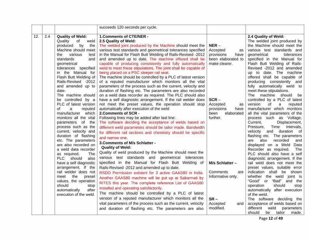
12. 2.4 Quality of Weld: Quality of weld produced by the Machine should meet the various test standards and geometrical tolerances specified in the Manual for Flash Butt Welding of Rails-Revised -2012 and amended up to date. The machine should be controlled by a PLC of latest version of a reputed manufacturer which monitors all the vital parameters of the process such as the current, velocity and duration of flashing etc. The parameters are also recorded on a weld data recorder as required. The PLC should also have a self diagnostic arrangement. If the rail welder does not meet the preset values, the operation should stop automatically after execution of the weld.
1.Comments of CTE/NER - 2.5 Quality of Weld: The welded joint produced by the Machine should meet the various test standards and geometrical tolerances specified in the Manual for Flash Butt Welding of Rails-Revised -2012 and amended up to date. The machine offered shall be capable of producing consistently and fully automatically weld to meet these stipulations. The joint shall be capable of being placed on a PSC sleeper rail seat. The machine should be controlled by a PLC of latest version of a reputed manufacturer which monitors all the vital parameters of the process such as the current, velocity and duration of flashing etc. The parameters are also recorded on a weld data recorder as required. The PLC should also have a self diagnostic arrangement. If the rail welder does not meet the preset values, the operation should stop automatically after execution of the weld 2.Comments of SCR - Following lines may be added after last line: The software deciding the acceptance of welds based on different weld parameters should be tailor made. Bandwidth for different rail sections and chemistry should be specific and narrow one. 3.Comments of M/s Schlatter - Quality of Weld:
Quality of weld produced by the Machine should meet the various test standards and geometrical tolerances specified in the Manual for Flash Butt Welding of Rails-Revised -2012 and amended up to date. RSDO Permission existent for 3 active GAAS80 in India. Another GAAS80 machine will be put up at Sabarmati by RITES this year. The complete reference List of GAAS80 installed and operating satisfactorily. The machine should be controlled by a PLC of latest version of a reputed manufacturer which monitors all the vital parameters of the process such as the current, velocity and duration of flashing etc. The parameters are also
NER – Accepted as provisions have been elaborated to make clearer. SCR – Accepted as provisions have been elaborated further. M/s Schlatter – Comments are Informative only. SR – Accepted and modified.
2.4 Quality of Weld: The welded joint produced by the Machine should meet the various test standards and geometrical tolerances specified in the Manual for Flash Butt Welding of Rails-Revised -2012 and amended up to date. The machine offered shall be capable of producing consistently and fully automatically weld to meet these stipulations. The machine should be controlled by a PLC of latest version of a reputed manufacturer which monitors all the vital parameters of the process such as Voltage, Current, Displacement, Pressure, Time intervals, velocity and duration of flashing etc. The parameters are also recorded and displayed on a Weld Data Recorder as required. The PLC should also have a self diagnostic arrangement. If the rail weld does not meet the preset values, suitable error indication shall be shown whether the weld joint is “Good” or “Bad” and the operation should stop automatically after execution of the weld. The software deciding the acceptance of welds based on different weld parameters should be tailor made.

Page 13 of 49
recorded on a weld data recorder as required. Fulfilled – Schlatter WeldAnalyzer system The PLC should also have a self- diagnostic arrangement. If the rail welder does not meet the preset values, the operation should stop automatically after execution of the weld. The digital, PLC welding processor system SWEP is the only system that monitors the welding process during the process in real time (self-diagnosis) and in case of deviations from the set parameters can independently interrupt the welding process until before the moment of upsetting. The WeldAnalyzer system displays the erroneous value in red on the monitor. A new welding can only be started after the cause of the error has been eliminated. The incorrect welding remains in the database for evaluation / quality control of the system / job. When the welding is restarted, the welding number is automatically reset so that the welding numbering of the long rail remains consistent. 4.Comments of SR – Existing Para shall be revised as below: The machine should be controlled by a PLC of latest version of a reputed manufacturer which monitors all the vital parameters of the process such as Voltage, Current, Displacement, Pressure and Time intervals, etc. at each stage. The parameters are also recorded and displayed on a Weld Data Recorder as required. The PLC should also have a self diagnostic arrangement. If the rail weld does not meet the preset values, suitable error indication shall be shown whether the weld joint is “Good” or “Bad”.
Bandwidth for different rail sections and chemistry should be specific and narrow one.
13. 2.5 Clamping Units Multiple clamps to be provided for holding the rails to prevent slippage during butting operation and to prevent abnormal indentation of the
1.Comments of NER - 2.6 Clamping Units The clamping unit should be capable of applying a load suitable for different section of rails i.e. upto 78 kg/m. Multiple clamps to be provided for holding the rails to prevent slippage during butting operation and to prevent abnormal indentation of the rails. The tenderer should specify the details of clamping cylinders and ratio of
NER – Accepted except rail section 78Kg/m.
2.5 Clamping Units: The clamping unit should be capable of applying a load suitable for different section of rails i.e. upto 68 Kg/m. Multiple clamps to be provided for holding the rails to prevent slippage during butting
Page 14 of 49
rails. The tenderer should specify the details of clamping cylinders.
Clamping and forging force 2.Comments of M/s Schlatter – An overview / description of the clamping system with GAAS80 are included in the attached presentation. 3.Comments of SR – Existing Para shall be revised as below. The Tenderer should specify the details of clamping cylinders to indicate the type of clamping, number of clamping cylinders and interfacing with the Brushing machine.
The clamping force should be sufficient enough to withstand the butting forces to avoid slippage of rails during butting. There should be no clamping marks on the rail head and rail foot to avoid fatigue break of the rail.
M/s Schlatter – Comments are Informative only. SR – Considered and modified.
operation and to prevent abnormal indentation of the rails. The bidder should specify the details of clamping cylinders and ratio of Clamping and forging force.
14. 2.6 Forging Unit: Forging unit should be of air/oil intensified type capable of applying forging force suitable for welding rails up to 68 Kg/meter. The control includes a servo system, which should be controlled by the PLC for fine control on the velocity of flashing. The forging action, which has to be as fast as possible, should be accomplished with the help of a gas charged accumulator. The accumulator system must be connected to filled/charged Nitrogen cylinder with required pressure gauge and other
1.Comments of NER 2.7 Forging Unit: Forging unit should be of air/oil intensified type capable of applying forging force suitable for welding rails up to 68 78 Kg/meter. The rams of forging unit shall be so placed so as to ensure equal distribution of the forging load across the interfaces. The control includes a servo system, which should be controlled by the PLC for fine control on the velocity of flashing. The forging action, which has to be as fast as possible, should be accomplished with the help of a gas charged accumulator. The accumulator system must be connected to filled/charged Nitrogen cylinder with required pressure gauge and other necessary fixture. If any deficiency of nitrogen gas is observed in accumulator, then it must be easily recouped by nitrogen cylinder. The unit should be capable of delivering suitable force for welding 68 78 Kg/m rails with UTS of 130Kg/mm2. In view of the heavy force involved, certain interlocks should be incorporated in the system. The weld initiation should not be done without clamping. Similarly, the machine should not retract after welding unless declamped. This is to avoid application of tensile force on the still plastic joint inadvertently after welding. 2.Comments of CTE/SCR Following lines may be added after last line: Forging unit’s hydraulic circuit should be isolated from other
NER – Accepted except rail section 78Kg/m, as it is not available in worldwide. Other changes made the provisions more clear. SCR – Suitable Hydraulic circuits may be used for welding of rails upto 68 Kg/m and upto 65m length. Hence, comments not considered.
2.6 Forging Unit: Forging unit should be of air/oil intensified type capable of applying forging force suitable for welding rails up to 68 Kg/meter. The rams of forging unit shall be so placed so as to ensure equal distribution of the forging load across the interfaces. The control includes a servo system, which should be controlled by the PLC for fine control on the velocity of flashing. The forging action, which has to be as fast as possible, should be accomplished with the help of a gas charged accumulator. The accumulator system must be connected to filled/charged Nitrogen cylinder with required pressure gauge and other necessary fixture. If any deficiency of nitrogen gas is observed in accumulator, then it must be easily recouped by nitrogen cylinder. The unit

Page 15 of 49
necessary fixture. If any deficiency of nitrogen gas is observed in accumulator, then it must be easily recouped by nitrogen cylinder. The unit should be capable of delivering suitable force for welding 68 Kg/m rails with UTS of 130Kg/mm2. In view of the heavy force involved, certain interlocks should be incorporated in the system. The weld initiation should not be done without clamping. Similarly, the machine should not retract after welding unless de-clamped. This is to avoid application of tensile force on the still plastic joint inadvertently after welding.
hydraulic circuits consisting of clamping, de-twisting, lifting cylinders, etc. as mentioned in para 2.11. 3.Comments of M/s Schlatter – Fulfilled - An description and picture of the forging accumulator system with GAAS80 are included in the attached presentation.
M/s Schlatter – Comments are Informative only.
should be capable of delivering suitable force for welding 68 Kg/m rails with UTS of 130Kg/mm2. In view of the heavy force involved, certain interlocks should be incorporated in the system. The weld initiation should not be done without clamping. Similarly, the machine should not retract after welding unless de-clamped. This is to avoid application of tensile force on the still plastic joint inadvertently after welding.
15. 2.7 Electrodes These are to be of copper alloy, water cooled with quick release facilities for maintenance before replacement. Suitable welding electrodes should be provided for the rail sections to
1.Comments of NER 2.8 Welding Electrodes: These are to be of copper alloy, water cooled with quick release facilities for maintenance and before replacement. Suitable welding electrodes should be provided for the rail sections as per IRS/T-12 to be welded. Arrangement should be provided to blow off scale and flash from the electrodes. Electrodes supplied with machine shall be the part of welding machine and will have the same warranty as specified for the welding machine. The codal life of the
NER - Partially accepted and modified. Warranty of electrodes equal to welding machine is not justified. SCR- Accepted as
2.7 Welding Electrodes: These are to be of copper alloy with high abrasion with relatively good conductivity and water cooled with quick release facilities for maintenance and replacement. Metallurgical composition of copper alloy of electrodes to be specified to take care of

Page 16 of 49
be welded. Arrangement should be provided to blow off scale and flash from the electrodes. Electrodes supplied with machine shall be the part of welding machine and will have the same warranty as specified for the welding machine. The codal life of the electrodes in terms of number of welds should not be less than 25000. The number of spare electrodes supplied with the machine shall be two sets. The electrode holders shall have a provision for vertical adjustment to compensate the wear up to 25 mm.
electrodes in terms of number of welds should not be less than 25000. The number of spare electrodes supplied with the machine shall be two sets. The electrode holders shall have a provision for vertical adjustment to compensate the wear up to 25 mm. The equipment to cool the water circulated in Electrode should be included with the machine. 2.Comments of SCR Electrodes These are to be of copper alloy, water cooled with quick release facilities for maintenance before replacement. Metallurgical composition of copper alloy of electrodes to be specified to take care of replacement of electrodes in case manufacturers do not support servicing of FBW unit after certain period. Suitable welding electrodes should be provided for the rail sections to be welded. Arrangement should be provided to blow off scale and flash from the electrodes. Electrodes supplied with machine shall be the part of welding machine and will have the same warranty as specified for the welding machine. The codal life of the electrodes in terms of number of welds should not be less than 25000. The number of spare electrodes supplied with the machine shall be two sets. The electrode holders shall have a provision for vertical adjustment to compensate the wear up to 25 mm. 3.Comments of M/s Schlatter - Fulfilled. Schlatter GAAS80 electrodes have much longer life span than your requirement as they are not directly involved in the clamping of the rails. However, as a rule, our electrodes meet the required service life when used under optimum conditions. The actual service life can also be shorter if the pre-cleaning of the electrode contact surfaces and / or the daily maintenance and care of the machines are not carried out correctly. The main advantage of Schlatter FBW machine is that the electrodes are independent of the clamping unit, hence the life expectancy is much higher. 4.Comments of SR - Existing Para shall be revised as below. These are to be of copper alloy with high abrasion with relatively good conductivity and water cooled with quick
provision is elaborated further. M/s Schlatter – Comments are Informative only. SR - Considered and incorporated. M/s NENCKI – No comments.
replacement of electrodes in case manufacturers do not support servicing of FBW unit after certain period. Suitable welding electrodes should be provided for the rail sections upto 68 Kg/m to be welded. Arrangement should be provided to blow off scale and flash from the electrodes. Electrodes supplied with machine shall be the part of welding machine. The codal life of the electrodes in terms of number of welds should not be less than 25000. The number of spare electrodes supplied with the machine shall be two sets. The electrode holders shall have a provision for vertical adjustment to compensate the wear up to 25 mm. The equipment to cool the water circulated in Electrode should be included with the machine.

Page 17 of 49
release facilities for maintenance before replacement. 5. Comments of M/s NENCKI, Switzerland – Not applicable for Nencki Machines. Part of Flash Butt Welding manufacturer.
16. 2.8 Breaking & Inching Mechanism: The welding machine should be provided with an independent breaking and inching mechanism on each side so as to permit the welding operator to correct position of the rails without any impact.
1.Comments of M/s Schlatter – The welding machine has an emergency stop system to avoid damage to the machine or the operators. At the control panel, at the switch cabinet and at the ends of the machine, the corresponding shutters are open and accessible. 2. Comments of M/s NENCKI, Switzerland – Not applicable for Nencki Machines. Part of Flash Butt Welding manufacturer.
M/s Schlatter – Comments are Informative only. M/s NENCKI – No comments.
2.8 Breaking & Inching Mechanism: The welding machine should be provided with an independent breaking and inching mechanism on each side so as to permit the welding operator to correct position of the rails without any impact.
17. 2.9 Rail Alignment & Twist Correction: Flash Butt Welding Machine should be equipped with automatic rail ends alignment facility. Rail alignment (lateral and vertical) and de-twist facility should be incorporated in the fixed and moving heads of the machine for execution of the weld in perfect geometric alignment fully automatically over a length of 1 m. There should be provision of manual adjustment in case cross section of two rail ends being welded have major
1.Comments of NER - 2.10 Rail Alignment & Twist Correction: Flash Butt Welding Machine should be equipped with automatic rail ends alignment facility. Rail alignment (lateral and vertical) and de-twist facility should be incorporated in the fixed and moving heads of the machine for execution of the weld in perfect geometric alignment fully automatically over a length of 1 m. There should be no need of any manual adjustment while welding the new rails. Arrangement through sensors which reads and records maximum mismatch in alignment between Gauge faces should be provided. Automatic selection of Gauge face should be possible. The aligning force and de twisting force shall be sufficient for maximum rail section to be welded. Visual indication should be available for correct alignment. Automatic rail alignment setup should be capable to perform alignment as per stipulations of Manual for Flash Butt Welding of Rails-2012. There should be provision of manual adjustment in case cross section of two rail ends being welded have major mismatch for welding of released rails. Adequate lighting arrangement should be available inside the machine to enable visual check of alignment and matching of rail ends
NER - Provision is elaborated further, hence accepted.
2.9 Rail Alignment & Twist Correction: Flash Butt Welding Machine should be equipped with automatic rail ends alignment facility. Rail alignment (lateral and vertical) and de-twist facility should be incorporated in the fixed and moving heads of the machine for execution of the weld in perfect geometric alignment fully automatically over a length of 1 m. There should be no need of any manual adjustment while welding the new rails. Arrangement through sensors which reads and records maximum mismatch in alignment between Gauge faces should be provided. Automatic selection of Gauge face should be possible. The aligning force and detwisting

Page 18 of 49
mismatch. Visual indication should be available for correct alignment. Automatic rail alignment setup should be capable to perform alignment as per stipulations of Manual for Flash Butt Welding of Rails-2012. Adequate lighting arrangement should be available inside the machine to enable visual check of alignment and matching of rail ends.
2.Comments of SCR - Rail Alignment & Twist Correction: Flash Butt Welding Machine should be equipped with automatic rail ends alignment facility. Rail alignment (lateral and vertical) and de-twist facility should be incorporated in the fixed and moving heads of the machine for execution of the weld in perfect geometric alignment fully automatically over a length of 1 m. There should be provision of manual adjustment in case cross section of two rail ends being welded have major mismatch. Visual display indication should be available for correct alignment. Automatic rail alignment setup should be capable to perform alignment as per stipulations of Manual for Flash Butt Welding of Rails-2012. Adequate lighting arrangement should be available inside the machine to enable visual check of alignment and matching of rail ends. (The guides of rail aligning device should be suitable for 52/60kg rail sections). 3.Comments of M/s Schlatter – Fulfilled - A description and some picture of the alignment and clamping system which meets the requirements described is an integral part of the machine. And are included in the attached presentation. 4. Comments of M/s NENCKI, Switzerland – Not applicable for Nencki Machines. Part of Flash Butt Welding manufacturer.
SCR – Modified and corrected. Rail section already considered in para 2.0 M/s Schlatter – Comments are Informative only. M/s NENCKI – No comments.
force shall be sufficient for maximum rail section to be welded. Visual display should be available for correct alignment. Automatic rail alignment setup should be capable to perform alignment as per stipulations of Manual for Flash Butt Welding of Rails-2012. There should be provision of manual adjustment in case cross section of two rail ends being welded have major mismatch for welding of released rails. Adequate lighting arrangement should be available inside the machine to enable visual check of alignment and matching of rail ends.
18. 2.10 Automatic Stripping Unit: The welding unit should have a trimming arrangement as an integral part of the unit so that it can trim the excess upset immediately after welding. The weld should be in compression during trimming and removal of excess upset. The
1.Comments of NER - 2.11 Automatic Stripping Unit: The welding unit should have a trimming arrangement as an integral part of the unit so that it can trim the excess upset immediately after welding. The weld should be in compression during trimming and removal of excess upset. The action of stripping should be controlled completely by the welder automatic sequence panel. The trimmer should have the capability to trim excess hot upset metal all round the rail section in such a way that minimum grinding is required to achieve final finished profile at weld as prescribed in Flash Butt Welding Manual. The maximum thickness of trimmed surface shall be in accordance with provisions of item (v) of Part ‘A’ & ‘B’ of Annexure-IV of Flash Butt Welding Manual-2012.
NER - Provision is elaborated further, hence accepted. SCR – Specifications of trimming dies/cutting edges etc. have covered
2.10 Automatic Stripping Unit:
The welding unit should have a trimming arrangement as an integral part of the unit so that it can trim the excess upset immediately after welding. The action of stripping should be controlled completely by the welder automatic sequence panel. The trimmer should have the capability to trim excess hot upset metal all round the rail section in such a way that minimum grinding is

Page 19 of 49
trimmer should have the capability to trim excess hot upset metal all round the rail section in such a way that minimum grinding is required to achieve final finished profile at weld as prescribed in Flash Butt Welding Manual. The maximum thickness of trimmed surface shall be in accordance with provisions of item (v) of Part ‘A’ & ‘B’ of Annexure-IV of Flash Butt Welding Manual-2012. Suitable trimming dies should be provided for the rail sections to be welded. There should be a well designed weld chips collection trolley which shall be capable to dispose the burn chips away from trench of Main Welding Machine.
Suitable trimming dies should be provided for the rail sections to be welded. Sufficient force shall be available for stripper for upset removal from any rail section/ Metallurgy which the machine is capable of welding. There should be a well designed weld chips collection trolley which shall be capable to dispose the burn chips away from trench of Main Welding Machine. 2.Comments of SCR - Automatic Stripping Unit: The welding unit should have a trimming arrangement as an integral part of the unit so that it can trim the excess upset immediately after welding. The weld should be in compression during trimming and removal of excess upset. The trimmer should have the capability to trim excess hot upset metal all round the rail section in such a way that minimum grinding is required to achieve final finished profile at weld as prescribed in Flash Butt Welding Manual. The maximum thickness of trimmed surface shall be in accordance with provisions of item (v) of Part ‘A’ & ‘B’ of Annexure-IV of Flash Butt Welding Manual-2012. 5 sets of Suitable trimming dies should be provided for the rail sections to be welded. Metallurgical specifications of trimming dyes/cutting edges and specification of welding electrodes for reconditioning to be specified. There should be a well designed weld chips collection trolley which shall be capable to dispose the burn chips away from trench of Main Welding Machine. 3.Comments of M/s Schlatter – Fulfilled - A description and some picture of the automatic stripping system which meets the requirements described is an integral part of the machine. Picture and drawings are included in the attached presentation. 4.Comments of SR – Additional Para to be included as below. The stripping unit should be of movable design against the rails clamped in position. 5. Comments of M/s NENCKI, Switzerland – Not applicable for Nencki Machines. Part of Flash Butt Welding manufacturer.
under “Maintenance Spare” in clause 12. M/s Schlatter – Comments are Informative only. SR – The welding unit should have a trimming arrangement as an integral part of the unit so that it can trim the excess upset immediately after welding. This provision covers the movable design
required to achieve final finished profile at weld as prescribed in Flash Butt Welding Manual. The maximum thickness of trimmed surface shall be in accordance with provisions of item (v) of Part ‘A’ & ‘B’ of Annexure-IV of Flash Butt Welding Manual-2012. Suitable trimming dies should be provided for the rail sections to be welded. Sufficient force shall be available for stripper for upset removal from any rail section/ Metallurgy which the machine is capable of welding. There should be a well designed weld chips collection trolley which shall be capable to dispose the burn chips away from trench of Main Welding Machine.
Page 20 of 49
of stripping unit M/s NENCKI – No comments.
19. 2.11 Hydraulic Power Pack The machine shall have a Hydraulic power pack consisting of suitable units for the servo valve system and other requirements of the welding machine. The servo system should be sensitive to contamination, isolated and maintained with greater care. The unit should include oil reservoir, oil cooler, motor pump assemblies, associated filters, gauges, sensors, pressure relief valves, etc. for protection and long life of the hydraulic system. The equipment should be capable of operation at an ambient temperature up to 550C. Onboard system for filtration and monitoring the quality of hydraulic oil in hydraulic circuit should be provided. The gauge should
1.Comments of NER 2.12 Hydraulic Power Pack: The machine shall have a Hydraulic power pack consisting of suitable units for the servo valve system and other requirements of the welding machine. The servo system should be sensitive to contamination, isolated and maintained with greater care. The unit should include oil reservoir, oil cooler, motor pump assemblies, associated filters, gauges, sensors, pressure relief valves, etc. for protection and long life of the hydraulic system. The equipment should be capable of operation at an ambient temperature up to 550 C. On board system for filtration and monitoring the quality of hydraulic oil in hydraulic circuit should be provided. The gauge should clearly indicate that the hydraulic oil is contaminated beyond the permissible limits and requires immediate replacement. The manifolds of valve system should preferably be placed and fixed outside the machine frame to avoid damage due to constant vibration and should be placed at convenient height. The hydraulic parts should be of renowned brand and its spare parts and service facilities should be available in India. 2.Comments of SCR Following line may be added after last line: A separate filtering unit to be provided for hydraulic oil used in circuits before it enters hydraulic oil cooling system. 3.Comments of M/s Schlatter – Fulfilled - A description and picture of the hydraulic power pack which meets the requirements described as an integral part of the machine. Picture are included in the attached presentation. Note - Schlatter uses Bosch Rexroth, Germany make hydraulic unit which is the best in the world. The service and parts are easily available through their local subsidiary worldwide and in particular India. 4.Comments of SR - Existing Para shall be revised as below. The machine shall have two separate Hydraulic power
NER – Accepted. It is required to avoid damage of valve system due to vibration. SCR – Accepted as provisions are elaborated to make clearer. M/s Schlatter – Comments are Informative only.
2.11 Hydraulic Power Pack: The machine shall have a Hydraulic power packs consisting of suitable units for the servo valve system and other requirements of the welding machine. The servo system should be sensitive to contamination, isolated and maintained with greater care. The unit should include oil reservoir, oil cooler, motor pump assemblies, associated filters, gauges, sensors, pressure relief valves, etc. for protection and long life of the hydraulic system. The equipment should be capable of operation at an ambient temperature up to 550 C. On board system for filtration and monitoring the quality of hydraulic oil in hydraulic circuit should be provided. The gauge should clearly indicate that the hydraulic oil is contaminated beyond the permissible limits and requires immediate replacement. The Hydraulic oil used shall be of commercially available specification. The manifolds of valve system should preferably be placed and fixed outside the machine frame to avoid damage due to constant vibration and should

Page 21 of 49
clearly indicate that the hydraulic oil is contaminated beyond the permissible limits and requires immediate replacement.
packs consisting of suitable units for the servo valve system and other requirements of the welding machine. The servo system should be sensitive to contamination, isolated and maintained with greater care. The unit should include oil reservoir, oil cooler, motor pump assemblies, associated filters, gauges, sensors, pressure relief valves, etc. for protection and long life of the hydraulic system. The equipment should be capable of operation at an ambient temperature up to 550C. Onboard system for filtration and monitoring the quality of hydraulic oil in hydraulic circuit should be provided. The gauge should clearly indicate that the hydraulic oil is contaminated beyond the permissible limits and requires immediate replacement. The Hydraulic Oil used shall be of commercially available specification. 5. Comments of M/s NENCKI, Switzerland – Not applicable for Nencki Machines. Part of Flash Butt Welding manufacturer.
SR - Instead of two suitable units, it may be any number, hence not considered. Second para considered and added. M/s NENCKI – No comments.
be placed at convenient height. The hydraulic parts should be of renowned brand and its spare parts and service facilities should be available in India. A separate filtering unit to be provided for hydraulic oil used in circuits before it enters hydraulic oil cooling system.
20. 2.12 Electrical power Pack The welding process will be based on Direct Current for a uniform and fast heat accumulation in the work piece. The three phase mains connection shall have a uniform power load possible and has a power factor better than 0.85.
1.Comments of NER - 2.13 Electrical power Pack: The Electrical equipments should be fully tropicalized. The equipment should suit connection to 400/440 volts 3 phase 50 cycle (HZ) supply. The machine shall be capable of adjusting/withstanding to a voltage fluctuation up to +10% while in operation. A voltage stabilizer of 440 volt shall be provided in mains supply of main welding machine to minimize the voltage fluctuation and provide appropriate voltage to mains of electrical power pack. The welding process will be based on Direct Current for a uniform and fast heat accumulation in the work piece. The three phase mains connection shall have a uniform power load possible and has a power factor better than 0.85. The secondary circuits of the transformers should be cooled to prevent over-heating. A wide range of secondary voltages should be available to allow for the correct heating conditions to be selected for individual rail sizes. The energy consumption per weld in KWH should be indicated for different rail sections. 2.Comments of SCR Following line may be added after last line: The manufacturer needs to stipulate the specifications of the
NER – Accepted as provisions are elaborated to make clearer. SCR – Accepted and
2.12 Electrical power Pack: The Electrical equipments should be fully tropicalized. The equipment should suit connection to 400/440 volts 3 phase 50 cycle (HZ) supply. The machine shall be capable of adjusting/withstanding to a voltage fluctuation up to +10% while in operation. A voltage stabilizer of 440 volt shall be provided in mains supply of main welding machine to minimize the voltage fluctuation and provide appropriate voltage to mains of electrical power pack. The welding process will be based on Direct Current for a uniform and fast heat accumulation in the work piece. The three phase mains connection shall have a

Page 22 of 49
transformers required for functioning of FBW plant. 3.Comments of M/s Schlatter – Fulfilled - A detailed description and some picture and drawing are included in the attached presentation. 4. Comments of M/s NENCKI, Switzerland – Not applicable for Nencki Machines. Part of Flash Butt Welding manufacturer.
modified. M/s Schlatter – Comments are Informative only. M/s NENCKI – No comments
uniform power load possible and has a power factor better than 0.85. The secondary circuits of the transformers should be cooled to prevent over-heating. A wide range of secondary voltages should be available to allow for the correct heating conditions to be selected for individual rail sizes. The energy consumption per weld in KWH should be indicated for different rail sections. The manufacturer needs to stipulate the specifications of the transformers required for functioning of FBW plant.
21. 2.13 Centralised Lubrication - Automatic Lubrication to be provided for the machine. The frequency of lubrication shall be programmable.
1.Comments of M/s Schlatter – Fulfilled. 2. Comments of M/s NENCKI, Switzerland – Not applicable for Nencki Machines. Part of Flash Butt Welding manufacturer.
M/s Schlatter – No comments. M/s NENCKI – No comments
2.13 Centralised Lubrication - Automatic Lubrication is to be provided for the machine. The frequency of lubrication shall be programmable.
22. 2.14 Cooling System: The cooling system shall be efficient and designed for maximum ambient temperature of 55°C. Supplier may note that the Machine shall be working under extreme dusty conditions and the cooling mechanism should be
1.Comments of NER - 2.15 Cooling System of Machine: The cooling system shall be efficient and designed for maximum ambient temperature of 55°C. Supplier may note that the Machine shall be working under extreme dusty conditions and the cooling mechanism should be maintainable under these conditions for all prime movers. Adequate heat transfer arrangement for the hydraulic system shall be designed and provided so that under extreme heat conditions, the temperature of system oil does not go beyond limit recommended by Oil Company. The installation of requisite device/system for temperature control of machine/ welding electrodes will be part of this
NER – Accepted as provisions are elaborated to make clearer. M/s Schlatter – No comments.
2.14 Cooling System of Machine:
The cooling system shall be efficient and designed for maximum ambient temperature of 55°C. Supplier may note that the Machine shall be working under extreme dusty conditions and the cooling mechanism should be maintainable under these conditions for all prime movers. Adequate heat

Page 23 of 49
maintainable under these conditions for all prime movers. Adequate heat transfer arrangement for the hydraulic system shall be designed and provided so that under extreme heat conditions, the temperature of system oil does not go beyond limit recommended by Oil Company.
item. 2.Comments of M/s Schlatter – Fulfilled.
transfer arrangement for the hydraulic system shall be designed and provided so that under extreme heat conditions, the temperature of system oil does not go beyond limit recommended by Oil Company. The installation of requisite device/system for temperature control of machine/ welding electrodes will be part of this item.
23. 3.0 Programmable Logic Control (PLC) Flash Butt welding of rails involves accurate and dependable control of current of the order of 70,000 Amps. PLC, AD/DA conversions, sensor-actuator links etc. enables accurate performance. The tenderer should specify the details of PLC incorporating with the machine.
1.Comments of NER - 2.16 Programmable Logic Control (PLC) Flash Butt welding of rails involves accurate and dependable control of current of the order of 70,000 Amps. PLC, AD/DA conversions, sensor-actuator links etc. enables accurate performance. The tenderer should specify the details of PLC incorporating with the machine. 2.Comments of M/s Schlatter – Pls refer point 1.1 (ii) above. 3.Comments of SR – Additional Para to be included as below. The PLC Software listing shall be issued in the form of a Ladder Diagram along with the Operating Manual. 4. Comments of M/s NENCKI, Switzerland – Not applicable for Nencki Machines. Part of Flash Butt Welding manufacturer.
NER – No change, only paragraph has been changed. M/s Schlatter – No comments. SR – Considered and modified. M/s NENCKI – No comments
3.0 Programmable Logic Control (PLC): Flash Butt Welding of rails involves accurate and dependable control of current of the order of 70,000 Amps. PLC, AD/DA conversions, sensor-actuator links etc. enables accurate performance. The bidder should specify the details of PLC incorporating with the machine. The PLC Software listing shall be issued in the form of a Ladder Diagram along with the Operating Manual.
24. 4.0 Weld Data Recorder:
Automatic microprocessors weld control recorder
1.Comments of NER 3.0 Computer based Weld Data Recording and Monitoring Equipment:
This equipment should be capable of being wired/ connected directly to the rail welding machine and give an
NER – Accepted as provisions are elaborated to make clearer.
4.0 Computer based Weld Data Recording and Monitoring Equipment:
This equipment should be capable of being wired/

Page 24 of 49
should be provided to record data pertaining to each weld such as temperature, voltage, current, upset pressure and total welding time. It should be of the digital print out type in which the various values are printed in one colour (say blue) when they are within limits. Otherwise these are printed in other colour (say red). For every red print there should be a small audible beep. The weld data recorder must be capable for online monitoring of weld sequence and quality of weld joints. The recording system should be a computer based data acquisition system specifically designed to record entire weld process in detail for complete weld process analysis. The data logger will have a minimum capacity to store one lakh welds data for retrieval and study. The hardware consists of a single
immediate read out which in comparison with pre-fed master data should automatically identify any inconsistency in welding machine operation. Automatic microprocessors weld control recorder should be provided to record data pertaining to each weld such as temperature, voltage, current, upset pressure and total welding time. It should be of the digital print out type in which the various values are printed in one colour (say blue) when they are within limits. Otherwise these are printed in other colour (say red). For every red print there should be a small audible beep. The weld data recorder must be capable for online monitoring of weld sequence and quality of weld joints. The recording system should be a computer based data acquisition system specifically designed to record entire weld process in detail for complete weld process analysis. The data logger will have a minimum capacity to store one lakh welds data for retrieval and study. The hardware consists of a single processing unit, a processor unit (PC type) with hard memory, disk drive a touch screen video display unit and Keyboard. The second remote monitoring unit will consist of a basic computer with laser/ink jet printer. The weld parameters sensed and operated upon by the machine control are to be communicated to the recorder through a suitable communication port. All these signals are to be recorded in coded form in the memory in the recorder for further retrieval, if desired. Parameters to be recorded for each weld: Date & time of welding Joint serial number Section of the rail Pre weld alignment Welding current in Amps (2 channels) Line voltage in Volts Welding voltage in Volts (2 channels) Clamping pressure Kg/cm2 Butting pressure Kg/cm2 Number of Pre-Heats Pre Heat time On - Off in sec. Burn off time in sec. Flashing time in sec.
.
connected directly to the rail welding machine and give an immediate read out which in comparison with pre-fed master data should automatically identify any inconsistency in welding machine operation. Automatic microprocessors weld control recorder should be provided to record data pertaining to each weld such as temperature, voltage, current, upset pressure and total welding time. It should be of the digital print out type in which the various values are printed in one colour (say blue) when they are within limits. Otherwise these are printed in other colour (say red). For every red print there should be a small audible beep. The weld data recorder must be capable for online monitoring of weld sequence and quality of weld joints. The recording system should be a computer based data acquisition system specifically designed to record entire weld process in detail for complete weld process analysis. The data logger will have a minimum capacity to store one lakh welds data for retrieval and study. In order to minimize intervention to alter standardized input parameters, the software should have the facility of password protection for

Page 25 of 49
processing unit, a processor unit (PC type) with hard memory, disk drive a touch screen video display unit and Keyboard. The second remote monitoring unit will consist of a basic computer with laser/ink jet printer. The weld parameters sensed and operated upon by the machine control are to be communicated to the recorder through a suitable communication port. All these signals are to be recorded in coded form in the memory in the recorder for further retrieval, if desired. Parameters to be recorded in each weld: Date & time of welding Joint Sr. No. Section of the rail Welding current in Amps (2 channels) Line voltage in Volts Welding voltage in Volts (2 channels) Clamping pressure Kg/cm2
Total stroke in mm. Butting stroke in mm. Total time in sec. Upset length i.e. rail consumed per weld (mm) Heat soak back duration Post heat delay Post Heat ON Time Post Heat OFF Time Number of post Heats The system offered should be capable of building upto limit of 99 sets of parameters. The supplier shall describe the elements employed in the system with the details of the manufacturer. It should be ensured that consumable spares and repair facilities of the system are available in India. It should be possible to locate the system in a separate room situated upto 40 meters away from the welding machine. The system shall be compatible with other machines supplied with plant for automatic feeding and maintaining the data base of complete weld from Pre-straightening to final finishing phase. 2.Comments of SCR - Weld Data Recorder: Automatic microprocessors weld control recorder should be provided to record data pertaining to each weld such as temperature, voltage, current, upset pressure and total welding time. It should be of the digital print out type in which the various values are printed in one colour (say blue) when they are within limits. Otherwise these are printed in other colour (say red). For every red print there should be a small audible beep. The weld data recorder must be capable for online monitoring of weld sequence and quality of weld joints. The recording system should be a computer based data acquisition system specifically designed to record entire weld process in detail for complete weld process analysis. The data logger will have a minimum capacity to store one lakh welds data for retrieval and study. In order to minimize intervention to alter standardized input parameters, the software should have the facility of password protection for modification of these parameters.
SCR – Accepted as prevents data from vandalism.
modification of these parameters. The hardware consists of a single processing unit, a processor unit (PC type) with hard memory, disk drive a touch screen video display unit and Keyboard. The second remote monitoring unit will consist of a basic computer with laser/ink jet printer. The weld parameters sensed and operated upon by the machine control are to be communicated to the recorder through a suitable communication port. All these signals are to be recorded in coded form in the memory in the recorder for further retrieval, if desired. Parameters to be recorded for each weld: Date & time of welding Joint serial number Section of the rail Pre weld alignment Welding current in Amps
(2 channels) Line voltage in Volts Welding voltage in Volts (2
channels) Clamping pressure Kg/cm2 Butting pressure Kg/cm2 Number of Pre-Heats Pre Heat time On - Off in sec. Burn off time in sec. Flashing time in sec. Total stroke in mm. Butting stroke in mm.

Page 26 of 49
Butting pressure Kg/cm2 Number of Pre-Heats Pre Heat time On - Off in sec. Burn off time in sec. Flashing time in sec. Total stroke in mm. Butting stroke in mm. Total time in sec. Upset length i.e. rail consumed per weld (mm) The supplier shall describe the elements employed in the system with the details of the manufacturer.
No change in other Para 3. Comments of NR- Butting force and total time of weld should also be recorded as in mobile plant. 4. Comments of M/s Schlatter – Fulfilled - Schlatter WeldAnalyzer- System based on a Windows operated PC integral Part of scope of supply with detailed description and some picture are included in the attached presentation. 5.Comments of SR – “Weld Data Recorder” – This title should be as “weld Data digital display and weld recorder”. The machine should have to display the parameters for every weld in a lively manner and printing as and when required. Copying to other PC/System also shall be feasible even during welding process. Existing Para-2 shall be corrected as below. The hardware shall consist of a Signal Conditioning Unit and a Data Logger unit (PC type) with hard memory, external USB disk drive port, a Touch screen video display unit and keyboard. The second remote monitoring unit will consist of a basic computer with laser/inkjet printer. Following additional points to be included under Parameters to be recorder for each weld : Duration of Butting Slippage of Rail (Yes or No) Weld Analysis (GOOD or BAD) 6. Comments of M/s NENCKI, Switzerland – Not applicable for Nencki Machines. Part of Flash Butt Welding manufacturer.
NR – Butting pressure and total time of weld already mentioned in specification. M/s Schlatter – Comments are Informative only. SR – Conidered and modified. M/s NENCKI – No comments.
Total time in sec. Upset length i.e. rail consumed per weld (mm) Heat soak back duration Post heat delay Post Heat ON Time Post Heat OFF Time Number of post Heats Duration of Butting Slippage of Rail (Yes or
No) Weld Analysis (GOOD or
BAD) The system offered should be capable of building upto 99 sets of parameters.
The supplier shall describe the elements employed in the system with the details of the manufacturer. It should be ensured that consumable spares and repair facilities of the system are available in India. It should be possible to locate the system in a separate room situated upto 40 meters away from the welding machine. The system shall be compatible with other machines supplied with plant for automatic feeding and maintaining the data base of complete weld from Pre-straightening to final finishing phase.
25. 5.0 Smoke Trapping Device- All smoke and spark
1.Comments of NER - 4.0 Smoke Trapping Device/ Fume Extraction Equipment:
NER – Accepted as provisions are
5.0 Smoke Trapping Device/ Fume Extraction Equipment:
Page 27 of 49
material shall be trapped by device and deposited in the receptacle. Fumes and dust must be sucked out from the welding chamber and passes through a cyclone separator and exhausted to the atmosphere though a chimney of suitable height. The particulate matter must be collected in a bin at the bottom of the separator. It must ensure that there is no discomfort to operator due to welding fumes and dust. The cyclone separator should be mounted outside the shed which houses the flash butt welder. Only the suction ducting should be brought in and connected through suitable flexible ducting to permit the machine traverse for rail panel positioning. The motor control should be mounted inside the shed for easy access to the rail flash butt welding operator. The fume extractor should be
All smoke and spark material shall be trapped by device and deposited in the receptacle. Fumes and dust must be sucked out from the welding chamber and passes through a cyclone separator and exhausted to the atmosphere though a chimney of suitable height. The particulate matter must be collected in a bin at the bottom of the separator. The bin shall have adequate capacity for at least day’s production to avoid frequent removal. It must ensure that there is no discomfort to operator due to welding fumes and dust and operator is fully protected from the spatter. The cyclone separator should be mounted outside the shed which houses the flash butt welder. Only the suction ducting should be brought in and connected through suitable flexible ducting to permit the machine traverse for rail panel positioning. The motor control should be mounted inside the shed for easy access to the rail flash butt welding operator. The fume extractor should be interlocked with the Flash butt welder to ensure that it is in operation before welding commences. 2.Comments of M/s Schlatter - Part of the scope of delivery is a smoke extraction hood to which an exhaust system can then be connected. Exhaust system is part of the scope of delivery of project by Maco Corporation. 3. Comments of M/s NENCKI, Switzerland – Not applicable for Nencki Machines. Part of Flash Butt Welding manufacturer.
elaborated to make clearer. M/s Schlatter – No change referred. M/s NENCKI – No comments.
All smoke and spark material shall be trapped by device and deposited in the receptacle. Fumes and dust must be sucked out from the welding chamber and passes through a cyclone separator and exhausted to the atmosphere though a chimney of suitable height. The particulate matter must be collected in a bin at the bottom of the separator. The bin shall have adequate capacity for atleast day’s production to avoid frequent removal. It must ensure that there is no discomfort to operator due to welding fumes and dust and operator is fully protected from the spatter. The cyclone separator should be mounted outside the shed which houses the flash butt welder. Only the suction ducting should be brought in and connected through suitable flexible ducting to permit the machine traverse for rail panel positioning. The motor control should be mounted inside the shed for easy access to the rail flash butt welding operator. The fume extractor should be interlocked with the Flash butt welder to ensure that it is in operation before welding commences.

Page 28 of 49
interlocked with the Flash butt welder to ensure that it is in operation before welding commences.
26. 6.0 Automatic Cooling Device: Adequate cooling arrangements (Air/liquid) for cooling of welded rails to normal temperature should be provided.
1.Comments of NER - 2.17 Automatic Cooling Device: Adequate cooling arrangements (Air/liquid) for cooling of welded rails to normal temperature should be provided. The cooling arrangement for all rail sections and rail steel should be quick enough so as not to reduce the capacity of plant i.e. 20 joints per hour. The arrangement shall be specified by tenderer. 2.Comments of M/s Schlatter - Air cooling device type Voest Alpine and associated compressor is supplied as a separate part and must be used / operated manually. 3. Comments of M/s NENCKI, Switzerland – Welds must cool down to a certain temperature naturally, see RDSO handbook. If cool down is forced, microstructural changes in the rail may apply.
NER – Accepted as provisions are elaborated to make clearer. M/s Schlatter – System should be automatic. M/s NENCKI – Provisions are as per RDSO’s Manual for Flash Butt Welding of Rails, Revised 2012. Air/water cooling can be done when temperature 3500C as per provisions of the Manual for Flash Butt Welding of Rails-2012.
6.0 Automatic Cooling Device: Adequate cooling arrangements (Air/liquid) for cooling of welded rails to normal temperature should be provided. The cooling arrangement for all rail sections and rail steel should be quick enough so as not to reduce the capacity of plant i.e. 20 joints per hour. The arrangement shall be specified by the bidder.
27. 7.0 Post Weld heat treatment: Equipment should provide for post heat treatment facilities with necessary control features. This device among other thing shall enable the post heating sequence being set to pre-determine temperature and
1.Comments of NER - 2.18 Post Weld heat treatment: Equipment should provide for post heat treatment facilities with necessary control features. This device among other thing shall enable the post heating sequence being set to pre-determine temperature and cooling time with a selector switch to bring in the automatic post heat cycle whenever required. In case of welding of 1080 grade chromium rails and 1080 grade Head Hardened rails, controlled cooling and fast cooling (quenching) shall be required respectively to maintain the properties of parent rail in heat affected zone. The facility should preferably be in-built with the welding machine.
NER - Accepted as provisions are elaborated to make clearer.
7.0 Post Weld heat treatment: Alloy steel rails and heat treated/head hardened rails need post weld heat treatment to ensure variation in hardness within acceptable limits in heat affected zone. Suitable equipment should be provided for post heat treatment facilities with necessary control features. This device among other thing shall enable the

Page 29 of 49
cooling time with a selector switch to bring in the automatic post heat cycle whenever required. In case of welding of 1080 grade chromium rails and 1080 grade Head Hardened rails, controlled cooling and fast cooling (quenching) shall be required respectively to maintain the properties of parent rail in heat affected zone. These facilities should be either in built with the machine or provided separately on the welding line at the adjustable distance from the machine. The up-gradation should be possible by adding new component or the system should be compatible for up-gradation.
The facilities, if proposed to be provided separately on the welding line at the adjustable distance from the machine, should have proper interlock with main welding machine to be incorporated in welding cycle. The up-gradation should be possible by adding new component or the system should be compatible for up-gradation. 2.Comments of M/s Mechelonic- Built in post heat facility will increase cycle time. 3.Comments of M/s Schlatter - The FBW GAAS80 is not equipped with an integrated after heat treatment module for forced cooling of head hardened rails. We supply a separate cooling unit type VoestAlpine with an electric compressor for installation near the welding machine. 4. Comments of M/s NENCKI, Switzerland – Post weld heat treatment: described in RDSO Handbook, Annex. I, Para 5.4 (Page 22), here described features are not necessary, production time will be much higher, recommended distances available in handbook. The solution described in RDSO Handbook, Annex. I, Para 5.4 (Page 22) is a very practical and simple solution and is more than sufficient to get good results. Post weld air quenching treatment: described in RDSO Handbook, Annex. II, Para 5.4 (Page 23).
M/s Mechelonic- Considered and provision has made optional. M/s Schlatter - considered and provision has made optional. M/s NENCKI – Suitable equipments may be provided.
post heating sequence being set to pre-determine temperature and cooling time with a selector switch to bring in the automatic post heat cycle whenever required. The facility should preferably be in-built with the welding machine. The facilities, if proposed to be provided separately on the welding line at the adjustable distance from the machine, should have proper interlock with main welding machine to be incorporated in welding cycle.
28. 8.0 Specification for Stand by Generator- A suitable diesel operated generating set with adequate capacity to feed welding transformer, compressor, electric hoists, Goliath crane
1.Comments of NER - 5. Specification for Stand by Diesel Generator:
A suitable diesel operated generating set with adequate capacity to feed welding transformer, compressor, electric hoists, Goliath crane and motorized line etc. to be supplied with the welding plant as standby for welding operation. The basis for deciding capacity should be clearly brought out in the offer.
NER - Accepted as provisions are elaborated to make clearer.
8.0 Stand by Diesel Generator:
8.1 A suitable diesel operated generating set with adequate capacity to feed welding transformer, compressor, electric hoists, Goliath crane and motorized line etc. to be
Page 30 of 49
and motorized conveyer line etc. to be supplied with the welding plant as standby for welding operation.
The generator shall be powered by indigenous diesel engine and shall have proven record of service in tropical conditions. The detailed technical literature and specifications along with manufacturer’s literature should accompany the offer. 2. Comments of NR- All the machines including generators should be sound proof (sound level should be within the limit) 3. Comments of M/s Schlatter – Noted. Part of scope of supply of Maco Corporation. Pls refer technical specification sheet attached. 4. Comments of SR- Existing Para shall be corrected as below. Backup power supply shall be provided with Two Diesel operated Gensets. One Genset with adequate capacity shall feed the Welding Machine including Control Panel, Weld Data Recorder, Hydraulic Power Packs, Chiller Unit, Stripping Unit, Brushing Device, Smoke Trapping Device which are essential for the Welding process. The second GenSet with suitable capacity shall feed the flow line machinery such as Conveyors, Hoist, Air Compressors, Grinding Machines, Rail Straightening Machine, Testing equipments, etc. 5. Comments of M/s NENCKI, Switzerland – Not applicable for Nencki Machines. Part of Flash Butt Welding manufacturer. 6. Comments of TMM Dte – 8.1 A suitable diesel operated generating set with adequate capacity to feed welding transformer, compressor, electric hoists, Goliath crane and motorized line etc. to be supplied with the welding plant as standby for welding operation. The basis for deciding capacity should be clearly brought out in the offer. The generator shall be powered by indigenous diesel engine and shall have proven record of service in tropical conditions. The detailed technical literature and specifications along with manufacturer’s literature should accompany the offer.
8.2 The engine should have Electronic Control Module (ECM) or similar arrangement for taking out operating
NR- Modified provision incorporated as clause 20.3 M/s Schlatter – Comments are Informative only. SR- A suitable diesel operated generating set with adequate capacity will fulfil the requirement. M/s NENCKI – No comments. TMM Dte – Accepted and modified accordingly.
supplied with the welding plant as standby for welding operation. The basis for deciding capacity should be clearly brought out in the offer.
The generator shall be powered by indigenous diesel engine and shall have proven record of service in tropical conditions. The detailed technical literature and specifications along with manufacturer’s literature should accompany the offer.
8.2 The engine should have Electronic Control Module (ECM) or similar arrangement for taking out operating parameters on real time basis such as RPM, load, temperature, pressure and diagnostic data as well as trip and historical data. These data should be displayed and stored on a centralized computer and monitoring system. It should also be possible to transfer these data on USB device through the centralized computer based control.
8.3 In order to adhere to pollution Control norms, the diesel engine should be electronically controlled emmissionized engine with minimum compliance of tier 2 stage.
8.4 The engine should be enclosed in a weather

Page 31 of 49
parameters on real time basis such as RPM, load, temperature, pressure and diagnostic data as well as trip and historical data. These data should be displayed and stored on a centralized computer and monitoring system. It should also be possible to transfer these data on USB device through the centralized computer based control.
8.3 In order to adhere to pollution Control norms, the diesel engine should be electronically controlled emmissionized engine with minimum compliance of tier 2 stage.
8.4 The engine should be enclosed in a weather protective, sound and dust resistant enclosure to minimize engine noise and to prevent oozing out of oil spills etc. from engine area to the adjacent components like alternator, hoses, electrical cables fittings as a protection against fire. All doors on the enclosure shall be strategically located in areas as to allow ease of maintenance of the engine and allow good access to and visibility of instruments, controls, engine gauges, etc. sufficient louvers shall be provided to allow the total engine cooling air requirements used in this application.
protective, sound and dust resistant enclosure to minimize engine noise and to prevent oozing out of oil spills etc. from engine area to the adjacent components like alternator, hoses, electrical cables fittings as a protection against fire. All doors on the enclosure shall be strategically located in areas as to allow ease of maintenance of the engine and allow good access to and visibility of instruments, controls, engine gauges, etc. Sufficient louvers shall be provided to allow the total engine cooling air requirements used in this application.
29. 9.0 9.1
Rail End Brushing Machine: Brushing Machine for cleaning of rail end along with dust evacuation before welding in order to establish uniform contact on running surface. The machine shall be capable to remove the scale rust and other grit from the rails using steel wire brushes. The brushing process should ensure optimal contact resistance between the rails and the welding electrodes.
1.Comments of NER - 6.0 Automatic Rail End Brushing Machine: 6.1 Brushing Machine shall be so designed that it will automatically clean the specified area of rail along with dust evacuation before welding in order to establish uniform contact on running surface. The machine shall be capable to remove the scale rust and other grit from the rails using steel wire brushes. The brushing process should ensure optimal contact resistance between the rails and the welding electrodes. The operation shall meet the provisions of the Manual for flash butt welding of rails issued by RDSO. 2.Comments of NR - Suction and dust collection system should also be available in machine. 3. Comments of M/s Schlatter – Noted. Part of scope of supply of Maco Corporation as bought out in case of Turnkey execution of FBWP. Pls refer technical specification sheet attached. 4. Comments of M/s NENCKI, Switzerland – Noted. Draft specifications are enclosed herewith for your reference.
NER – Accepted as provisions are elaborated to make clearer. NR – Accepted and incorporated as clause 9.6. M/s Schlatter – Comments are Informative only.
9.0 Automatic Rail End Brushing Machine: 9.1 Brushing Machine shall be so designed that it will automatically clean the specified area of rail along with dust evacuation before welding in order to establish uniform contact on running surface. The machine shall be capable to remove the scale, rust and other grit from the rails using steel wire brushes. The brushing process should ensure optimal contact resistance between the rails and the welding electrodes. The operation shall meet the provisions of the Manual for flash butt welding of rails issued by RDSO.
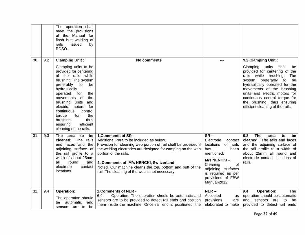
Page 32 of 49
The operation shall meet the provisions of the Manual for flash butt welding of rails issued by RDSO.
30. 9.2 Clamping Unit : Clamping units to be provided for centering of the rails while brushing. The system preferably to be hydraulically operated for the movements of the brushing units and electric motors for continuous control torque for the brushing, thus ensuring efficient cleaning of the rails.
No comments --- 9.2 Clamping Unit : Clamping units shall be provided for centering of the rails while brushing. The system preferably to be hydraulically operated for the movements of the brushing units and electric motors for continuous control torque for the brushing, thus ensuring efficient cleaning of the rails.
31. 9.3 The area to be cleaned: The rails end faces and the adjoining surface of the rail profile to a width of about 25mm all round and electrode contact locations.
1.Comments of SR - Additional Para to be included as below. Provision for cleaning web portion of rail shall be provided if the welding electrodes are designed for camping on the web portion of the rails. 2. Comments of M/s NENCKI, Switzerland – Noted. Our machine cleans the top, bottom and butt of the rail. The cleaning of the web is not necessary.
SR – Electrode contact locations of rails has been mentioned.
M/s NENCKI – Cleaning of adjoining surfaces is required as per provisions of FBW Manual-2012
9.3 The area to be cleaned: The rails end faces and the adjoining surface of the rail profile to a width of about 25mm all round and electrode contact locations of rails.
32. 9.4 Operation: The operation should be automatic and sensors are to be
1.Comments of NER - 6.4 Operation: The operation should be automatic and sensors are to be provided to detect rail ends and position them inside the machine. Once rail end is positioned, the
NER – Accepted as provisions are elaborated to make
9.4 Operation: The operation should be automatic and sensors are to be provided to detect rail ends
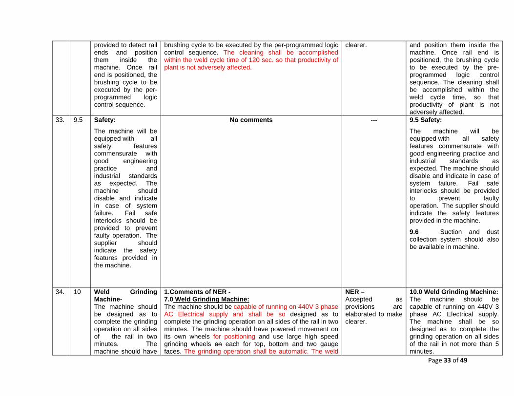
Page 33 of 49
provided to detect rail ends and position them inside the machine. Once rail end is positioned, the brushing cycle to be executed by the per-programmed logic control sequence.
brushing cycle to be executed by the per-programmed logic control sequence. The cleaning shall be accomplished within the weld cycle time of 120 sec. so that productivity of plant is not adversely affected.
clearer. and position them inside the machine. Once rail end is positioned, the brushing cycle to be executed by the pre-programmed logic control sequence. The cleaning shall be accomplished within the weld cycle time, so that productivity of plant is not adversely affected.
33. 9.5 Safety: The machine will be equipped with all safety features commensurate with good engineering practice and industrial standards as expected. The machine should disable and indicate in case of system failure. Fail safe interlocks should be provided to prevent faulty operation. The supplier should indicate the safety features provided in the machine.
No comments --- 9.5 Safety: The machine will be equipped with all safety features commensurate with good engineering practice and industrial standards as expected. The machine should disable and indicate in case of system failure. Fail safe interlocks should be provided to prevent faulty operation. The supplier should indicate the safety features provided in the machine.
9.6 Suction and dust collection system should also be available in machine.
34. 10 Weld Grinding Machine- The machine should be designed as to complete the grinding operation on all sides of the rail in two minutes. The machine should have
1.Comments of NER - 7.0 Weld Grinding Machine: The machine should be capable of running on 440V 3 phase AC Electrical supply and shall be so designed as to complete the grinding operation on all sides of the rail in two minutes. The machine should have powered movement on its own wheels for positioning and use large high speed grinding wheels on each for top, bottom and two gauge faces. The grinding operation shall be automatic. The weld
NER – Accepted as provisions are elaborated to make clearer.
10.0 Weld Grinding Machine: The machine should be capable of running on 440V 3 phase AC Electrical supply. The machine shall be so designed as to complete the grinding operation on all sides of the rail in not more than 5 minutes.

Page 34 of 49
powered movement on its own wheels and use large high speed grinding wheels on each for top, bottom and two gauge faces. Wheel dressing arrangement must be designed to run on 440V AC 3 phase.
finish tolerance as specified in the “Manual for flash butt welding of rails” issued by RDSO should be achieved after grinding. Wheel dressing arrangement should be built in the machine. It shall be ensured that indigenously available grinding stones can be used on this machine. 2. Comments of NR – Machine should have PLC control, dust collection system, Internal digital measuring and recording system. 3.Comments of M/s Mechelonic Semi-automatic profile grinding machine with manual grinding support is preferred as a automatic machine will take too long time for grinding, reducing production.3. 4. Comments of M/s Schlatter – Noted. Part of scope of supply of Maco Corporation as bought out in case of Turnkey execution of FBWP. Pls refer technical specification sheet attached. Firm has also mentioned at Para 2.3 that grinding operation takes approx. 5 - 6 minutes and thus determines the hourly output of a long rail welding plant. 5. Comments of M/s NENCKI, Switzerland – Not possible in 2 minutes No Machine in the world is able to grind the rail profile in 2 mins. Cycle time of the Nencki Grinding Machine is approx. 5 minutes (if tolerances of the rail and weld are met). Our machine grinds the top and both sides of the Railhead. The dressing of the grinding wheel is not necessary.
NR – Accepted and incorporated. M/s Mechelonic – Not accepted as automatic grinding operation is more reliable. M/s Schlatter – Accepted and provisions made for one or two grinding machines, so that production may not hamper. M/s NENCKI – Accepted and provisions made for one or two grinding machines, so that production may not hamper.
In order to maximize the output of the welding plant as a whole, more than one automatic grinding machine may be planned in the same welding line or an alternative line, as per layout of the plant. The machine should have powered movement on its own wheels for positioning and use large high speed grinding wheels each for top, bottom and two gauge faces. The grinding operation shall be automatic. The weld finish tolerance as specified in the “Manual for flash butt welding of rails” issued by RDSO should be achieved after grinding. It shall be ensured that indigenously available grinding stones can be used on this machine. Machine should have PLC control, dust collection system, Internal digital measuring and recording system.
35. 11 Specification for Rail Straightening Machine (Pre and Post Weld) The post straightening machine should be capable of re-moving the bad alignment in
1.Comments of NER - 8.0 Specification for Rail Straightening Machine (Pre and Post Weld):
8.1 The Pre Straightening machine is required to correct rail end of rails to be welded and this machines shall be stationary with suitable inching movement for placement of rails in the press. The Post Straightening machine is required to correct the weld alignment and this machine
NER - Accepted except rails section 78 Kg/m as provisions are elaborated to make clearer.
11.0 Rail Straightening Machine (Pre and Post Weld): 11.1 The Pre Straightening machine is required to correct rail end of rails to be welded and this machine shall be stationary with suitable inching movement for placement of

Page 35 of 49
the welded flash butt joints and should suit various rail sections i.e. 52Kg, 60Kg & 68 Kg. The machine should provide alignment correction in vertical and lateral direction and should have powered travelling arrangement for adjusting to different lengths of rails being welded. The machine should also have misalignment measuring device and also visual indicator to point out the location and extent of misalignment. The alignment correction supports should be moveable so as to handle short and long kinks. The pre-straightening press should be provided as a stationary press, where as the post-straightening press should be a mobile press. The press should be self-propelled for positioning on the rail to be straightened. A straightness measuring device
should be self propelled to adjust itself to correct weld location without affecting the welding line. Both the machines should be capable of correcting both vertical and lateral alignment for all the rail sections to be welded i.e. rails upto 78 kg/m. 8.2 The post straightening machine should be capable of re-moving the bad alignment in the welded flash butt joints and should suit various rail sections i.e. 52Kg, 60Kg & 68 Kg. The machine should provide alignment correction in vertical and lateral direction and should have powered travelling arrangement for adjusting to different lengths of rails being welded. The machine should also have misalignment measuring device and also visual indicator to point out the location and extent of misalignment. The alignment correction supports should be moveable so as to handle short and long kinks. 8.3 The pre-straightening press should be provided as a stationary press, where as the post-straightening press should be a mobile press. The press should be self propelled for positioning on the rail to be straightened. A straightness measuring device should be provided to measure and record the straightness of the rail at the joint. 8.4 The frame of presses must be of robust design. Adequate stiffeners and gusseting is to be provided for structural strength. All welded structures must be suitably stress relieved by heat treatment. The horizontal and vertical cylinders should not be integral with the main machine body to facilitate maintenance of the cylinders as modular units. 8.5 The laser measurement system should measure the straightness of the welded joint, and display it in a graphical form and stores the data in the tabular form. The laser measurement device must measure the head of the rail on the three surfaces, namely; Top Side, Front gauge face and Rear gauge face. The measurement should be done with the help of laser displacement sensor and the final straightness data should be stored in memory for later retrieval and analysis. If the rail is within the acceptable tolerance band the operation is complete or else the operator will have to repeat the cycle till the required straightness is achieved. 8.6 The Rail Straightening Machines should have a control system with PLC, key board and other required
rails in the press. The Post Straightening machine is required to correct the weld alignment and this machine should be self propelled to adjust itself to correct weld location without affecting the welding line. Both the machines should be capable of correcting both vertical and lateral alignment for all the rail sections to be welded i.e. rails upto 68 kg/m. 11.2 The post straightening machine should be capable of re-moving the bad alignment in the welded flash butt joints and should suit various rail sections. The machine should provide alignment correction in vertical and lateral direction and should have powered travelling arrangement for adjusting to different lengths of rails being welded. The machine should have misalignment measuring device and also visual indicator to point out the location and extent of misalignment. The alignment correction supports should be moveable so as to handle short and long kinks. 11.3 The pre-straightening press should be provided as a stationary press. A straightness measuring device should be provided to measure and record the straightness of the rail. 11.4 The frame of presses

Page 36 of 49
should be provided to measure and record the straightness of the rail at the joint. The frame must be of robust design. Adequate stiffeners and gusseting is to be provided for structural strength. All welded structures must be suitably stress relieved by heat treatment. The horizontal and vertical cylinders should not be integral with the main machine body to facilitate maintenance of the cylinders as modular units. The laser measurement system should measures the straightness of the welded joint, and displays it in a graphical form and stores the data in the tabular form. The laser measurement device must measure the head of the rail on the three surfaces, namely; Top Side, Front gauge face and Rear gauge face. The measurement should be done with the help of laser displacement sensor
devices. It should also have software to visualize the straightness of the rails, force supplied on the rails, the deformation process induced by straightening force and shall be displayed on the screen. The final alignment achieved shall automatically get recorded and stored for further analysis. This should be compatible with weld data recorder so that the data of press is fed to recorder for comprehensive record. 8.7 The design shall be such that manual verification of alignment is easily possible and area is well illuminated. The control panel should have provision for emergency stop for emergency and interlock to stop machine if deflection beyond pre-specified limit is exceeded to prevent breakage of rail. 2.Comments of SCR - No change in Para 1 & 2 The horizontal and vertical cylinders should not be integral with the main machine body to facilitate maintenance of the cylinders as modular units. The laser measurement system should measure the straightness of the welded joint, and displays it in a graphical form and stores the data should be stored in the tabular form. The laser measurement device must measure the head of the rail on the three surfaces, namely; Top Side, Front gauge face and Rear gauge face. No change in next Para 3.Comments of NR – Machine should have digital measurement system. 4. Comments of M/s Schlatter – Noted. Part of scope of supply of Maco Corporation as bought out in case of Turnkey execution of FBWP. Pls refer technical specification sheet attached. 5.Comments of SR – Additional Para to be included as below. Adequate spare dies for various rail sections such as 52kg / 60kg / 68kg shall be provided. In addition to various rail sections, various steel grades shall also be mentioned to include in 70 UTS, 90 UTS and 110 UTS and this should be included in under the Para 2.1 itself.
SCR – Accepted and modified. NR – Already incorporated. M/s Schlatter – Comments are Informative only.
must be of robust design. Adequate stiffeners and gusseting is to be provided for structural strength. All welded structures must be suitably stress relieved by heat treatment. The horizontal and vertical cylinders should not be integral with the main machine body to facilitate maintenance of the cylinders as modular units. 11.5 The laser measurement system should measure the straightness of the welded joint, and display it in a graphical form and data should be stored in the tabular form. The laser measurement device must measure the head of the rail on the three surfaces, namely; Top Side, Front gauge face and Rear gauge face. The measurement should be done with the help of laser displacement sensor and the final straightness data should be stored in memory for later retrieval and analysis. If the rail is within the acceptable tolerance band the operation is complete or else the operator will have to repeat the cycle till the required straightness is achieved. 11.6 The Rail Straightening Machines should have a control system with PLC, key board and other required devices. It should also have software to visualize the

Page 37 of 49
and the final straightness data should be stored in memory for later retrieval and analysis. If the rail is within the acceptable tolerance band the operation is complete or else the operator will have to repeat the cycle till the required straightness is achieved. The Rail Straightening Machines should have a control system with PLC, key board and other required devices. It should also have software to visualize the straightness of the rails, force supplied on the rails, the deformation process induced by straightening force shall be displayed on the screen.
6. Comments of M/s NENCKI, Switzerland – Post straightening: ok Note: Offset/steps between two welded rails cannot be aligned. Pre-straightening: A separate/additional machine will be necessary for pre-straightening the rail ends. It is not a part of the Nencki Straightening Machine.
SR – Suitable dies for different rail sections to be welded are included in clause 2.11. Rail sections and grades to be welded are mentioned at clause 2.1. M/s NENCKI – Requirement of two separate machines (Pre and Post Straightening) is mentioned.
straightness of the rails, force supplied on the rails, the deformation process induced by straightening force and shall be displayed on the screen. The final alignment achieved shall automatically get recorded and stored for further analysis. This should be compatible with weld data recorder so that the data of press is fed to recorder for comprehensive record. 11.7 The design shall be such that manual verification of alignment is easily possible and area is well illuminated. The control panel should have provision for emergency stop for emergency and interlock to stop machine if deflection beyond pre-specified limit is exceeded to prevent breakage of rail.
36. 12 Maintenance spares- The tenderers are required to furnish a detailed list of essential spare parts along with detailed drawings and specifications required for operation of entire plant for a
1.Comments of NER- 10.0 Maintenance spares: 10.1 The tenderers are required to furnish a detailed list of essential spare parts along with detailed drawings and specifications required for operation of entire plant for a period of two years. These spares should be included with the price of each equipment. 10.2 It should be necessary for the tenderer to indicate as to which of the parts listed can be procured indigenously and identifying the remaining items which are required to be necessarily imported.
NER – Accepted as provisions are elaborated to make more clear.
12.0 Maintenance spares: 12.1 The tenderers are required to furnish a detailed list of essential spare parts along with detailed drawings and specifications/metallurgical specifications required for operation of entire plant for a period of two years. These spares should be included with

Page 38 of 49
period of two years. These spares should be including with the price of each equipment. It should be necessary for the tenderer to indicate as to which of the parts listed can be procured indigenously identifying the remaining items which are required to be necessarily imported. The tenderer should give full particulars of the parts, part number, name of manufacturer etc. The unit price of all such items should also be furnished.
10.3 The tenderer should provide the itemized list of spare parts giving full particulars of the parts indicating part number, description, name of manufacturer, unit price, recommended quantity etc. The sketches/ drawings wherever required unit price of all such items should also be furnished. 2. Comments of NR – There should be provision of sufficient quantity of spare parts of various machines so as to maintain the machines for minimum 3 years after warranty period. List of spare parts with machine manual alongwith their stipulated life, the name of manufacturer etc. should be provided. 3. Comments of M/s Schlatter – Noted. Will be part of tender documents. 3. Comments of M/s NENCKI, Switzerland – A detailed spare part list is part of the offer.
NR – These have been covered under item of AMC. M/s Schlatter – No comments. M/s NENCKI – No comments.
the price of each equipment. 12.2 It should be necessary for the tenderer to indicate as to which of the parts listed can be procured indigenously and identifying the remaining items which are required to be necessarily imported. 12.3 The tenderer should provide the itemized list of spare parts giving full particulars of the parts indicating part number, description, name of manufacturer, unit price, recommended quantity etc. The sketches/ drawings wherever required should also be furnished.
37. 13 Consumable Stores- The tenderer should furnish detailed specification of all consumable stores except fuel required for the operation of the equipment offered including stripping unit and weld recorder together with the average expected
1.Comments of NER - 11.0 Consumable Stores:
The tenderer should furnish detailed specification of all consumable stores except fuel required for the operation of the equipment offered including stripping unit, grinding machines and weld recorder together with the average expected consumption rate for one single 08 hours shift per day, clearly indentifying whether all such items are indigenously available or whether any item is required to be imported on continuing counting basis. The unit price and quantity of all such items should be quoted. The consumable stores except fuel for a period of two years should be included in the quotation for the welding plant.
NER - Accepted and modified.
13.0 Consumable Stores:
The tenderer should furnish detailed specification of all consumable stores except fuel required for the operation of the equipment offered including stripping unit, grinding machines and weld recorder together with the average expected consumption rate for one single 08 hours shift per day, clearly indentifying whether all

Page 39 of 49
consumption rate for one single 08 hours shift per day, clearly indentifying whether all such items are indigenously available or whether any item is required to be imported on counting basis. The price of all such items should be quoted. The consumable stores except fuel for a period of two years should be included in the quotation for the welding plant.
2.Comments of SCR- Consumable Stores- The tenderer should furnish detailed specification of all consumable stores except fuel required for the operation of the equipment offered including stripping unit and weld recorder together with the average expected consumption rate for one single 08 hours shift per day, clearly indentifying whether all such items are indigenously available or whether any item is required to be imported on counting basis. The price of all such items should be quoted. The consumable stores except fuel for a period of two years should be included in the tendered offer quotation for the welding plant. 3. Comments of M/s Schlatter – Noted. Will be part of tender documents 4. Comments of M/s NENCKI, Switzerland –A detailed list of the consumables is part of the offer.
SCR- Accepted and modified. M/s Schlatter – No Comments. M/s NENCKI – No comments.
such items are indigenously available or whether any item is required to be imported on continuing basis. The unit price and quantity of all such items should be quoted. The consumable stores except fuel for a period of two years should be included in the tendered offer for the welding plant.
38. 14 14.0 Installation of plant- 14.1 The installation of the plant should be undertaken by the suppliers of the plant or their agents in India, who should commission the same. The services of firm Engineer should be made available to install and operate the same for at least two months. Railway staff will also be trained by the supplier of the plant for 02 months in
1.Comments of NER - 9.0 Installation of plant: 9.1 The installation of the plant should be undertaken by the suppliers of the plant or their agents in India, who should commission the same. The services of firm’s Engineers should be made available to install and operate the same for at least two months. Railway staff will also be trained by the supplier of the plant for 02 months in regular operation of the plant, as part of the contract.
9.2 The installation includes the making foundation for machines as per requirement and design finalized by supplier, supply and providing all the Installation materials like bolts and nuts, brackets etc complete in all respect. should be provided in adequate quantities, quoting unit price and quantity recommended. Special tools required for installation/maintenance shall provided by the tenderer. 2. Comments of M/s Schlatter – Noted. The above scope of work is under Maco Corporation
NER – Accepted as provisions are elaborated to make clearer. M/s Schlatter –
14.0 Installation of plant: 14.1 The installation of the plant should be undertaken by the suppliers of the plant or their agents in India, who should commission the same. The services of firm’s Engineers should be made available to install and operate the same for at least two months. Railway staff will also be trained by the supplier of the plant for 02 months in regular operation of the plant, as part of the contract.
14.2 The installation includes the making foundation for machines as per requirement and design

Page 40 of 49
regular operation of the plant, as part of the contract. 14.2 Installation materials like bolts and nuts, brackets should be provided in adequate quantities, quoting unit price and quantity recommended. Special tools required for installation/ maintenance shall provided by the tenderer.
(India) Private Ltd. 3. Comments of M/s NENCKI, Switzerland – 14.1 Noted Installation will be done by Nencki service engineers from India and/or Switzerland. Training: For each Nencki-Machines (Brushing, Grinding, Straightening, testing) there will not more than 1 to 2 weeks per machine of training necessary. 14.2 Noted Installation materials like bolts, nuts and brackets are part of the scope of supply.
Comments are Informative only. M/s NENCKI – Comments are Informative only.
finalized by supplier, supply and providing all the Installation materials like bolts and nuts, brackets etc complete in all respect. Special tools required for installation/maintenance shall provided by the tenderer.
39. 15 15.0 Training of staff- 15.1 Two persons from the Railway will be trained, as part of this contract (including transportation from India and back, boarding, lodging etc.) for a period of one month each in country where similar machines are working. 15.2The audio visual material like films, video tapes, slides etc. will also be made available by the suppliers which may facilitate general training of the staff.
1.Comments of NER 12.0 Training of staff: 12.1 Two persons from the Railway will be trained, as part of this contract (including transportation from India and back, boarding, lodging etc.) for a period of one month each in Manufacturerer’s country or any other country where similar machines are working. The cost of training includes lodging, boarding, air passage etc. and training material to be provided. 12.2 In addition to above, the operating staff will be trained for day to day operation and maintenance during the two months period the plant is under operation of the supplier and thereafter for another period of 4 months. 12.3 The audio visual material like films, video tapes, slides etc. will also be made available by the suppliers which may facilitate general training of the staff. 2. Comments of NR – Three persons from the railway should be trained for period of one month at two countries 15 days each to learn best of the practices. 3. Comments of M/s Schlatter – Noted. Will be fulfilled. 4. Comments of M/s NENCKI, Switzerland – 15.1 Training from Indian person of one month at a similar factory is unusual and not necessary
NER - Accepted as provisions are elaborated to make clearer. NR – Two person training for a month will suffice the purpose. M/s Schlatter – No Comments. M/s NENCKI- Advance training is
15.0 Training of staff: 15.1 One copy of complete technical literature of machines/tools/equipments including installation, operation and service manuals/instructions and complete electrical & hydraulic, trouble shooting charts, component drawings/ description and other relevant technical details as a reference documents in soft & hard copies in English language. . 15.2 In addition to above, the operating staff will be trained for day to day operation and maintenance during the two months period the plant is under operation of the supplier and thereafter for another period of 4 months. 15.3 The audio visual
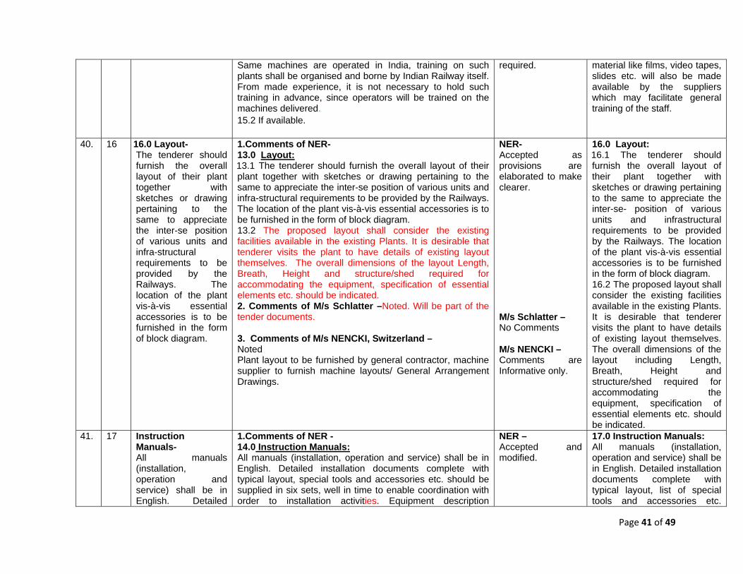
Page 41 of 49
Same machines are operated in India, training on such plants shall be organised and borne by Indian Railway itself. From made experience, it is not necessary to hold such training in advance, since operators will be trained on the machines delivered. 15.2 If available.
required. material like films, video tapes, slides etc. will also be made available by the suppliers which may facilitate general training of the staff.
40. 16 16.0 Layout- The tenderer should furnish the overall layout of their plant together with sketches or drawing pertaining to the same to appreciate the inter-se position of various units and infra-structural requirements to be provided by the Railways. The location of the plant vis-à-vis essential accessories is to be furnished in the form of block diagram.
1.Comments of NER- 13.0 Layout: 13.1 The tenderer should furnish the overall layout of their plant together with sketches or drawing pertaining to the same to appreciate the inter-se position of various units and infra-structural requirements to be provided by the Railways. The location of the plant vis-à-vis essential accessories is to be furnished in the form of block diagram. 13.2 The proposed layout shall consider the existing facilities available in the existing Plants. It is desirable that tenderer visits the plant to have details of existing layout themselves. The overall dimensions of the layout Length, Breath, Height and structure/shed required for accommodating the equipment, specification of essential elements etc. should be indicated. 2. Comments of M/s Schlatter –Noted. Will be part of the tender documents. 3. Comments of M/s NENCKI, Switzerland – Noted Plant layout to be furnished by general contractor, machine supplier to furnish machine layouts/ General Arrangement Drawings.
NER- Accepted as provisions are elaborated to make clearer. M/s Schlatter – No Comments M/s NENCKI – Comments are Informative only.
16.0 Layout: 16.1 The tenderer should furnish the overall layout of their plant together with sketches or drawing pertaining to the same to appreciate the inter-se- position of various units and infrastructural requirements to be provided by the Railways. The location of the plant vis-à-vis essential accessories is to be furnished in the form of block diagram. 16.2 The proposed layout shall consider the existing facilities available in the existing Plants. It is desirable that tenderer visits the plant to have details of existing layout themselves. The overall dimensions of the layout including Length, Breath, Height and structure/shed required for accommodating the equipment, specification of essential elements etc. should be indicated.
41. 17 Instruction Manuals- All manuals (installation, operation and service) shall be in English. Detailed
1.Comments of NER - 14.0 Instruction Manuals: All manuals (installation, operation and service) shall be in English. Detailed installation documents complete with typical layout, special tools and accessories etc. should be supplied in six sets, well in time to enable coordination with order to installation activities. Equipment description
NER – Accepted and modified.
17.0 Instruction Manuals: All manuals (installation, operation and service) shall be in English. Detailed installation documents complete with typical layout, list of special tools and accessories etc.

Page 42 of 49
installation documents complete with typical layout special tools and accessories etc. should be supplied in six sets, well in time to enable coordination with order to installation activity. Equipment description including installation, testing, schematic wiring, physical location, drawings, etc. shall be supplied.
including installation, testing, schematic wiring, physical location, drawings, etc. shall be supplied. 2.Comments of SCR Instruction Manuals- All manuals (installation, operation and service) shall be in English. Detailed installation documents complete with typical layout, list of special tools and accessories etc. should be supplied in six sets, well in time to enable coordination for with order to installation activity. Equipment description including installation, testing, schematic wiring, physical location, drawings, etc. shall be supplied. 3. Comments of M/s Schlatter – Noted. Will be fulfilled. 4. Comments of M/s NENCKI, Switzerland – Noted.
SCR – Change of wording does not change any meaning. M/s Schlatter – No Comments
should be supplied in six sets, well in time to enable coordination with order to installation activities. Equipment description including installation, testing, schematic wiring, physical location, drawings, etc. shall be supplied.
42. 18.0 18.1
Inspection of the Welding Plant All the equipment will be tested before dispatch by the technical inspection officers of Indian Embassy or authorized representative of Indian Railways. While inspecting the machine before dispatch from the supplier’s premises, the inspecting officer shall verify the conformity of the machine with respect to individual specification as above. The machine’s conformity/non-conformity issue in
1.Comments of NER - 15.0 Inspection of the Equipments of Welding Plant 2.Comments of SCR – 18.1 All the equipment will be tested before dispatch by the technical inspection officers of Indian Embassy or authorized representative of Indian Railways. In view of specialization of FBW machine, it is desirable that officials from RDSO (Metallurgical & chemical and Track directorate) and Zonal Railways shall comprise of members of technical inspection team. While inspecting the machine before dispatch from the supplier’s premises, the inspecting officer shall verify the conformity of the machine with respect to individual specification as above. The machine’s conformity/non-conformity issue in respect to each item shall be jointly recorded before issue of the inspection certificate and approval for dispatch of the machine as per Annexure –I enclosed. 3. Comments of M/s Schlatter – Noted. Will be fulfilled. 4.Comments of SR – Additional Para to be included as below. During the inspection, conformity tests shall be carried out as per Manual for Flash Butt Welding of Rails-Revised-2012
NER- Accepted and modified. SCR – Inspection team may be decided at later stage, this may not be part of specification. M/s Schlatter – No Comments SR – “The inspecting
18.0 Inspection of the Equipments/ Welding Plant 18.1 All the equipment will be tested before dispatch by the technical inspection officers of Indian Embassy or authorized representative of Indian Railways. While inspecting the machine before dispatch from the supplier’s premises, the inspecting officer shall verify the conformity of the machine with respect to individual specification as above. The machine’s conformity/non-conformity issue in respect to each item shall be jointly recorded before issue of the inspection certificate and approval for dispatch of the machine as per Annexure –I enclosed.
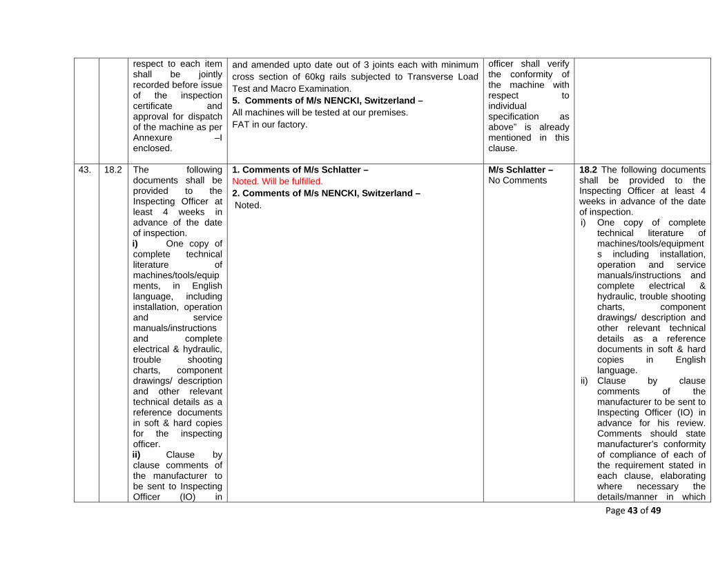
Page 43 of 49
respect to each item shall be jointly recorded before issue of the inspection certificate and approval for dispatch of the machine as per Annexure –I enclosed.
and amended upto date out of 3 joints each with minimum cross section of 60kg rails subjected to Transverse Load Test and Macro Examination. 5. Comments of M/s NENCKI, Switzerland – All machines will be tested at our premises. FAT in our factory.
officer shall verify the conformity of the machine with respect to individual specification as above” is already mentioned in this clause.
43. 18.2 The following documents shall be provided to the Inspecting Officer at least 4 weeks in advance of the date of inspection. i) One copy of complete technical literature of machines/tools/equipments, in English language, including installation, operation and service manuals/instructions and complete electrical & hydraulic, trouble shooting charts, component drawings/ description and other relevant technical details as a reference documents in soft & hard copies for the inspecting officer. ii) Clause by clause comments of the manufacturer to be sent to Inspecting Officer (IO) in
1. Comments of M/s Schlatter – Noted. Will be fulfilled. 2. Comments of M/s NENCKI, Switzerland – Noted.
M/s Schlatter – No Comments
18.2 The following documents shall be provided to the Inspecting Officer at least 4 weeks in advance of the date of inspection. i) One copy of complete
technical literature of machines/tools/equipments including installation, operation and service manuals/instructions and complete electrical & hydraulic, trouble shooting charts, component drawings/ description and other relevant technical details as a reference documents in soft & hard copies in English language.
ii) Clause by clause comments of the manufacturer to be sent to Inspecting Officer (IO) in advance for his review. Comments should state manufacturer’s conformity of compliance of each of the requirement stated in each clause, elaborating where necessary the details/manner in which

Page 44 of 49
advance for his review. Comments should state manufacturer’s conformity of compliance of each of the requirement stated in each clause, elaborating where necessary the details/manner in which the requirement has been complied. The proforma for the clause-wise comments is given below:
iii) Manufacturer’s Internal Quality Inspection Report of the machine. iv) Manufacturer’s quality certificate and/or test reports for
Cla
use
no.
Cla
use
Com
men
ts
of
man
ufac
ture
r
Com
men
ts
of
Insp
ectin
g O
ffice
r
the requirement has been complied. The proforma for the clause-wise comments is given below:
iii) Manufacturer’s Internal Quality Inspection Report of the machine.
iv) Manufacturer’s quality certificate and/or test reports for bought out assemblies/sub-assemblies to be provided to IO, containing serial number wherever applicable.
v) Draft Inspection Report to be prepared by the manufacturer, containing all Annexure mentioned at clause 18.3
Cla
use
no.
Cla
use
Comments of manufacturer
Comments of Inspecting Officer

Page 45 of 49
bought out assemblies/sub-assemblies to be provided to IO, containing serial number wherever applicable. v) Draft Inspection Report to be prepared by the manufacturer, containing all Annexure mentioned at clause 18.3
44. 18.3 List of documents to be annexed in the draft Inspection Report should include:
i. Maker’s Test Certificate.
ii. Manufacturer’s Internal Quality Inspection Report
iii. Quality Certificates of Bought out assemblies/sub-assemblies
iv. List of spare parts to be dispatched along with the machine
v. List of tools to be dispatched along with the machine
vi. List of Manuals, Drawings,
1. Comments of M/s Schlatter – Noted. Will be part of tender documents 2. Comments of M/s NENCKI, Switzerland – Noted
M/s Schlatter – No Comments
18.3 List of documents to be annexed in the draft Inspection Report should include: i. Maker’s Test Certificate. ii. Manufacturer’s Internal
Quality Inspection Report iii. Quality Certificates of
Bought out assemblies/sub-assemblies
iv. List of spare parts to be dispatched along with the machine
v. List of tools to be dispatched along with the machine
vi. List of Manuals, Drawings, Spare Parts Catalogues, etc. to be dispatched along with the machine, duly indicating the number of sets of each.

Page 46 of 49
Spare Parts Catalogues, etc. to be dispatched along with the machine, duly indicating the number of sets of each.
45. 19 Additional
information – 19.1 Names and address of the administration to which the equipment quoted has already been supplied by the tenderer should also be indicated. 19.2 The supply of drawing will in no way absolve the tenderer of his responsibilities of supplying the equipments strictly according to the specifications. 19.3 Four copies of test and inspection certificates for each equipment should be supplied along with the equipment.
1. Comments of NR- Any updation of plant with the upgradation of technology or as per requirement of railway in future upto 10 years which is possible with minor alteration/addition etc should be acceptable to OEM through agency. Most of the upgradation would be based on changes/modification in software of control panels of machine(s) in this regard. 2. Comments of M/s Schlatter – Noted. Will be part of the tender documents. 3. Comments of M/s NENCKI, Switzerland – 19.1 We suggest a specific eligibility/pre-qualification criteria to be imposed in order to assure the past supply and performance of the machine. 19.2 Noted 19.3 Noted
NR – Accepted and incorporated as new clause 19.4. M/s Schlatter – No Comments.
19.0 Additional information – 19.1 Names and address of the administration to which the equipment quoted has already been supplied by the tenderer should also be indicated. 19.2 The supply of drawing will in no way absolve the tenderer of his responsibilities of supplying the equipments strictly according to the specifications. 19.3 Four copies of test and inspection certificates for each equipment should be supplied along with the equipment. 19.4 Any updation of plant with the upgradation of technology or as per requirement of railway in future upto 10 years which is possible with minor alteration/addition etc should be acceptable to OEM through agency. Most of the upgradation would be based on changes/modification in software of control panels of machine(s) in this regard.
46. 20.0 Equipment Environment-
--- ---- 20.0 Equipment Environment-

Page 47 of 49
47. 20.1 Equipment It shall be capable of continuous operation during the varying atmospheric and climatic conditions prevailing throughout the year in India. The range of climatic conditions is as follows: - a. Ambient
temperature : -100 to 550C
b. Altitude: : Sea level to 1800 m above mean sea level
c. Humidity: : 40% to 100%
d. Rail temperature : (-) 10° C to (+) 75° C
1. Comments of M/s Schlatter – Noted. Fulfilled. There are 3 active machines already running in India. 2. Comments of M/s NENCKI, Switzerland – Noted
M/s Schlatter – Comments are informative only.
20.1 Equipment shall be capable of continuous operation during the varying atmospheric and climatic conditions prevailing throughout the year in India. The range of climatic conditions is as follows: - a. Ambient temperature : -
100 to 550C b. Altitude: : Sea level to
1800 m above mean sea level
c. Humidity: : 40% to 100% d. Rail temperature : (-) 10°
C to (+) 75° C
48. 20.2 The entire equipment should be thoroughly tropicalised for working in Indian conditions.
1. Comments of M/s Schlatter – Noted. Fulfilled. 2. Comments of M/s NENCKI, Switzerland – Noted
M/s Schlatter – No Comments.
20.2 The entire equipment should be thoroughly tropicalised for working in Indian conditions.
49. New ----- 2. Comments of NR against clause 8 All the machines including generators should be sound proof (sound level should be within the limit) 3. Comments of NR as a new clause mentioned at Sl. No. 58 – Various parameters regarding sound and air pollution should be provided by manufacturer with machine so that the same may be addressed rightly in case the plants are situated now at built up area.
NR- Accepted as modified in new clause 20.3.
20.3 All the machines including generators should be sound proof. Various parameters regarding sound and air pollution should be provided by manufacturer with machine so that the same may be addressed rightly in case the plants are situated at built up area.
50. 21 Warranty Clause: In addition to the special conditions of
1. Comments of NER- 18.0 Warranty Clause: In addition to the special conditions of contract dealing with
NER – Accepted and modified.
21.0 Warranty Clause: In addition to the special conditions of contract dealing

Page 48 of 49
contract dealing with warranty, the following will apply: Should any design modification be made in any part of the equipment offered, the period of 24 months would commence from the date of the modified part is commissioned in service for the purpose of that part and those parts which may get damaged due to defects in the new replaced part, the cost of such modification should be borne by the supplier.
warranty, the following will apply: Should any design modification be made in any part of the equipment offered, the period of Warranty (24 months) would commence from the date of the modified part is commissioned in service for the purpose of that part and those parts which may get damaged due to defects in the new replaced part, the cost of such modification should be borne by the supplier. 2. Comments of NR- 21&22. Warranty Clause/extended warranty & annual maintenance clause Warranty clause should have provision of extended warranty upto 3 years after the period of 2 years original warranty with moderate charges. It may also be looked into for the provision of 5 years AMC (after 2+3years warranty & extended warranty) so that smooth working at plant after commissioning of new plant may be ensured with good quality of machines and there critical parts. This will also help to establish the trend of maintenance required in machine at later stage. Proper safeguard of extended warranty and AMC may be ensured through appropriate clause of penalty clause. 3. Comments of M/s Schlatter – Noted. Will be part of the tender documents. 4. Comments of M/s NENCKI, Switzerland – We can grant 24 months on exchanged/modified parts.
NR – Two years warranty and five years AMC will suffice the purpose. M/s Schlatter – No Comments.
with warranty, the following will apply: Should any design modification be made in any part of the equipment offered, the period of Warranty (24 months) would commence from the date the modified part is commissioned in service for the purpose of that part and those parts which may get damaged due to defects in the new replaced part, the cost of such modification should be borne by the supplier.
51. 22 Annual Maintenance Contract (AMC): Tenderers are required compulsorily to quote for comprehensive annual maintenance contract per year for all machines and plants for a period of 5 years. The duration of AMC shall be of five years from the date of expiry of the warranty. The AMC
1.Comments of NER 19.0 Annual Maintenance Contract (AMC): 19.1 The Plant and connected machines will be required to be maintained for a period of Five (5) years after the expiry of warranty period. 19.2 For above, Tenderers are required compulsorily to quote for comprehensive annual maintenance contract per year for all machines and plants for a period of 5 years. The duration of AMC shall be of five years from the date of expiry of the warranty. The AMC will be inclusive of preventive maintenance services, day-to-day services, supply of all spares, maintenance material required and labour cost. All consumables except fuel, lubricating oils, hydraulic oil, toolings, drills and tapes shall form part of the scope of comprehensive AMC. 2.Comments of M/s Mechelonic
NER – Accepted as provisions are elaborated to make clearer.
22.0 Annual Maintenance Contract (AMC):
22.1 The Plant and connected machines will be required to be maintained for a period of Five (5) years after the expiry of warranty period. 22.2 For above, tenderers are required compulsorily to quote for comprehensive annual maintenance contract per year for all machines for a period of 5 years. The duration of AMC shall be of five years

Page 49 of 49
will be inclusive of preventive maintenance services, day-to-day services, supply of all spares, maintenance material required and labour cost. All consumables except fuel, lubricating oils, hydraulic oil, toolings, drills and tapes shall form part of the scope of comprehensive AMC.
It is suggested to train one Electrical and one Mechanical person from the operation side, who will maintain the plant on a day-to-day basis. We will provide daily maintenance schedule for this purpose. 3. Comments of M/s Schlatter – Noted. Will be submitted with the tender documents. 4. Comments of M/s NENCKI, Switzerland – Noted
M/s Mechelonic – Accepted. Day-to-day services have been removed from specification. M/s Schlatter – No Comments.
from the date of expiry of the warranty. The AMC will be inclusive of preventive maintenance services, supply of all spares, maintenance material required and labour cost. All consumables except fuel, lubricating oils, hydraulic oil, toolings, drills and tapes shall form part of the scope of comprehensive AMC.
52. -- New clause Comments of SCR - 22.1 Technical audit for every 20000 joints by OEM during AMC period shall be part of AMC.
SCR- Accepted and new clause 22.0 added.
22.3 Technical audit for every 20000 joints by OEM during AMC period shall be part of AMC.
53. -- New clause 1. Comments of NR- Various parameters regarding sound and air pollution should be provided by manufacturer with machine so that the same may be addressed rightly in case the plants are situated now at built up area.
NR – Accepted and added in clause 20.3
----