s. n. bose national centre for basic...
TRANSCRIPT
S. N. Bose National Centre for Basic SciencesBlock JD, Sector III, Salt Lake, Kolkata – 700098
(An autonomous national centre funded by the Department of Science & Technology, Government of India)
Tender No.SNB/PUR/OT/23/33 Date: 22/12/2013
OPEN TENDER
Sealed tender in two parts (separate technical bid and price bid) are invited in the name of Director, S. N. Bose National Centre for Basic Sciences from reputed equipment vendors for supply, installation, testing and commissioning for the following listed items. The detailed technical specifications and terms & conditions can be obtained from the website: http://www.bose.res.in. The sealed tenders must reach this office within 14 days from the date of publication of this advertisement.
Sl.No. Name of Item
1. 160kVA Uninterrupted Power Supply (UPS)2. High Performance Precision direct expansion air cooled, floor discharge type
Air Conditioning System
___________________
Registrar
S. N. Bose National Centre for Basic SciencesBlock JD, Sector III, Salt Lake, Kolkata – 700098
(An autonomous national centre funded by the Department of Science & Technology, Government of India)
NOTICE INVITING TENDERTender No.SNB/PUR/OT/23/33 Date: 22/12/2013
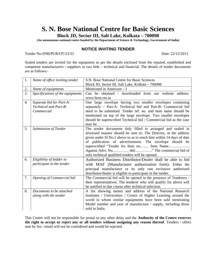
Sealed tenders are invited for the equipment as per the details enclosed from the reputed, established and competent manufacturers / suppliers in two bids – technical and financial. The details of tender documents are as follows:-
1. Name of office inviting tender S.N. Bose National Centre for Basic SciencesBlock JD, Sector III, Salt Lake, Kolkata – 700098
2. Name of equipments Mentioned in Annexure – I3. Specifications of the equipments Can be obtained / downloaded from our website address:
www.bose.res.in4. Separate bid for Part-A:
Technical and Part-B: Commercial
One large envelope having two smaller envelopes containing separately – Part-A: Technical bid and Part-B: Commercial bid need to be submitted. Tender ref. no. and item name should be mentioned on top of the large envelope. Two smaller envelopes should be superscribed Technical bid / Commercial bid as the case may be.
5. Submission of Tender The tender documents duly filled in arranged and sealed in aforesaid manner should be sent to: The Director, at the address given under Sl.No.1 above so as to reach him within 14 days of date of publication of advertisement. The envelope should be superscribed “Tender for Item no.…… Item Name.……………. Against Advt. No.………… dtd:………….” The commercial bid of only technical qualified tenders will be opened.
6. Eligibility of bidder to participate in the tender
Authorized Business Distributor/Dealer shall be able to bid with MAF (Manufacturer authorization form). Either the principal manufacturer or its only one exclusive authorized distributor/dealer is eligible to participate in the tender.
7. Opening of Commercial bid The Commercial bid will be opened in the presence of Tenderers / their representatives. The tenderer who will qualify for above will be notified in due course after technical selection.
8. Documents to be attached along with the tender
A list showing names and address of the National Research Institutes / Universities / Centre of Higher Learning around the world to whom similar equipments have been sold mentioning Model number and year of manufacture / supply, including those sold in India.
This Centre will not be responsible for postal or any other delay and the Authority of the Centre reserves the right to accept or reject any or all tenders without assigning any reason thereof. Tenders / offers sent by fax / email will not be considered and would be rejected.

DIRECTORS.N. BOSE NATIONAL CENTRE FOR BASIC SCIENCES

Annexure – I
Sl.No. Name of Item
1. 160kVA Uninterrupted Power Supply (UPS)2. High Performance Precision direct expansion air cooled, floor discharge type
Air Conditioning System
General Terms & Conditions:
1) The bid should be submitted in two bid system each of which is to be submitted in separate envelope. One envelope should contain “techno commercial bid” i.e., technical specifications, terms and condition, terms of payment except price and another envelope should contain price of the quoted item. Both the envelopes should be separately sealed and kept in another large envelope which should be marked with tender reference number, name of the equipment and tender opening date. Separate bid should be submitted for each of the items. Combined bids will not be entertained.
2) The tenderer should have high technical, financial reputation with sufficient experience and capable enough for supply, installation & commissioning of similar type of equipment to actual users. Documentary evidence should be submitted in this respect.
3) Against such offers, if statutory requirement demands clearance from concerned Governments the tenderers should confirm in their offer that “Export License” in that respect would be arranged by them at their cost.
4) Offers should be complete in all respect indicating therein the unit price(s) including manuals, make, model, duties and taxes, delivery period, gross and net weight of the consignment, terms of payment, together with the descriptive leaflet/catalogue/pamphlet/manufacturer’s brochure.
5) The offers shall remain valid at least for a period of 90 days. The period starts from the date of closing of tender submission.
6) The Institute shall not be responsible for delay, loss or non-receipt of the tender through post/Air Mail
7) The aforesaid Open Tender is being issued with no financial commitment and purchaser reserves the right to change / vary any items or items thereof at any stage.
8) No tenderer shall be entitled for any compensation what so ever for rejection/non consideration of their tender.
9) Invitation of tender does not constitute any right or claim for issue of purchase order to the tenderer.
10) Only Price Bids will be opened in presence of the technically qualified bidders or their authorized representative who choose to attend on the date and time informed to them after opening of technical bids and its evaluation.
11) The Centre will not be responsible for any misprinting by the news papers concerned and inaccessibility of the downloading facility for any reason whatsoever and in that case the tenderer(s) should contact to the tendering authority to verify the fact in case of confusion.
12) If any information furnished by the tenderer is found incorrect or false at a later stage he shall be liable to be debarred from ordering / tendering

13) For items originating from abroad 80% payment shall be made by letter of credit against sipping document and the balance 20% payment will be released after successful completion of supply, installation, testing & commissioning at site.
14) For indigenous item, payment will be made after supply, satisfactory installation, testing & commissioning of the equipment / instrument at site.
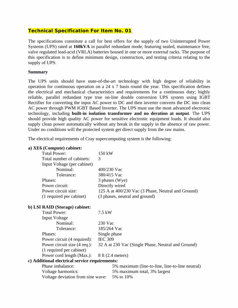
Technical Specification For Item No. 01
The specifications constitute a call for best offers for the supply of two Uninterrupted Power Systems (UPS) rated at 160kVA in parallel redundant mode, featuring sealed, maintenance free, valve regulated lead-acid (VRLA) batteries housed in one or more external racks. The purpose of this specification is to define minimum design, construction, and testing criteria relating to the supply of UPS.
Summary
The UPS units should have state-of-the-art technology with high degree of reliability in operation for continuous operation on a 24 x 7 basis round the year. This specification defines the electrical and mechanical characteristics and requirements for a continuous duty; highly reliable, parallel redundant type true on-line double conversion UPS system using IGBT Rectifier for converting the input AC power to DC and then inverter converts the DC into clean AC power through PWM IGBT Based Inverter. The UPS must use the most advanced electronic technology, including built-in isolation transformer and no deration at output. The UPS should provide high quality AC power for sensitive electronic equipment loads. It should also supply clean power automatically without any break in the supply in the absence of raw power. Under no conditions will the protected system get direct supply from the raw mains.
The electrical requirements of Cray supercomputing system is the following:
a) XE6 (Compute) cabinet:Total Power: 150 kWTotal number of cabinets: 3Input Voltage (per cabinet)
Nominal: 400/230 VacTolerance: 380/415 Vac
Phases: 3 phases (Wye)Power circuit: Directly wiredPower circuit size: 125 A at 400/230 Vac (3 Phase, Neutral and Ground)(1 required per cabinet) (3 phases, neutral and ground)
b) LSI RAID (Storage) cabinet:Total Power: 7.5 kWInput Voltage
Nominal: 230 VacTolerance: 185/264 Vac
Phases: Single phasePower circuit (4 required): IEC 309Power circuit size (4 req.): 32 A at 230 Vac (Single Phase, Neutral and Ground)(1 required per cabinet)Power cord length (Max.): 8 ft (2.4 meters)
c) Additional electrical service requirements:Phase imbalance: 5% maximum (line-to-line, line-to-line neutral)Voltage harmonics: 5% maximum total, 3% largestVoltage deviation from sine wave: 5% to 10%

Voltage modulation: <3%Transient voltage surges: +5%Transient voltage sags: -5%Frequency tolerance: 5%
The Technical specifications of the construction of UPS unit are as follows:
Design Specifications:
The Uninterruptible Power System (UPS) should include the following operational components:• Full IGBT Rectifier and battery charger
• IGBT Inverter
• Maintenance bypass switch
• Static switch at bypass
• Inbuilt within UPS panel double wound isolation transformer
• Batteries
Non-linear load Tolerance: Output voltage distortion < 3%Phase angle precision < 2%Frequency tolerance: < 3%Voltage Stability: < 2%
IGBT Rectifier and Battery charger: The IGBT Rectifier/Battery charger should have an input isolating switch and a PWM digital vector control system (DSP based) which, in addition to normal functions (AC/DC conversion), will automatically correct the input power factor to a value > 0.99 and limit the harmonic rejection to the mains at a THDi value < 3% at full output load, and a THDi value < 5% for any other condition.For the battery charger function, this converter should include built-in fuses and a control circuit for the voltage and battery recharging current. The ripple current to the batteries should be less than 0.05 C. A microprocessor control function should perform the following operations:
1. Test the battery by automatically performing a partial battery discharge at weekly intervals or at intervals defined by the user
2. Adjust battery float voltage as a function of ambient temperature
3. Calculate the remaining battery autonomy time during discharge
4. Automatically compensate battery shutdown voltage as a function of the time for prolonged discharges

IGBT Inverter:
The IGBT inverter should have a PWM digital vector control system (DSP based), capable of converting DC voltage from the IGBT rectifier or battery into AC voltage. A rated output filter should create an output voltage sinusoidal envelope. The control circuit, in addition to normal functions, should automatically adjust nominal output power in accordance with ambient temperature. Inverter should be able to deliver full active power at minimum 0.9 load power factor. Further, the unit should be able to deliver up to 10% additional power at 25º C.
The scope of work should cover the supply, installation & commissioning of 2x160 KVA parallel redundant UPS system along with isolation transformer (built in) and individual battery bank for each of the UPS unit. No additional hardware (direct) should be implemented in parallelization of two UPS.
UPS compatibility to Load Power factor :
UPS should support the full Power factor range (Lagging & leading) of load without any deration in power rating.
Supply Protection with Transient Voltage Surge Suppressors (TVSS):
All UPS should be protected from transient over-voltages by TVSS located at the input of the UPS and if required at the output also. TVSS device for equipment shall be as per following specifications.
• Surge Current Capacity : minimum of 50kA
• All Modes Protection : L-L, L-N, L-G, N-G
• Connection Type : Parallel
• Protection Level : < 1 kV
• MCOV : Min. 320 Volts
• Response Time : < 0.5 nanoseconds
• EMI/RFI Attenuation : 40 dB typical
• Status Indication : LED, Dry contacts
• Monitoring : Monitoring of All Modes, including N-E
• Fusing : Individual Fusing of MOV’s including N-G
• Certification : UL 1449-3 listing
• Enclosure : NEMA Tested
• Mounting : Wall Mounting
• Warranty : 5 Years

Static bypass switch:
The static bypass switch should feature a separate power input and will consist of the following:• Static switches (SCR type), which can support overloads and short circuits downstream of
the UPS
• A backfeed detection circuit as specified by IEC/EN 62040-1-1, clause 5.1.4
• A bypass and maintenance bypass input isolating switch with auxiliary indicator contact
• An output load switch
The control logic should be handled by digital algorithms (using vector control techniques), similar to those used for the rectifier and the inverter. The static bypass should be equipped with a backfeed protection device compliant with clause 5.1.4 of IEC/EN 62040-1-1; and a relay signal contact for the control of the external backfeed isolator to be installed on the bypass line upstream from the UPS.
Batteries:
The batteries should be 12V SMF lead acid and shall feature an enclosure made of self-extinguishing material. The batteries should be housed in one or more racks/cubicles and will be protected by fuses located on each pole and via a dedicated switch.
Batteries will have an operating life of minimum 3 years and, in the event of total failure of the mains power source, will guarantee the supply of nominal UPS output power for a minimum of (15 + 15) total 30 minutes in full load condition. Number of battery block per bank should be clearly mentioned, and the total VAhrs should be clearly stated. Battery bus-bar voltage should not exceed 600 V. The batteries should be from approved makes of Global Batteries (Rocket), Exide, Quanta only.
Operating Modes:
This section describes the different operating modes of the Uninterruptible Power System.
The UPS systems should work in parallel redundant mode of operation with equal sharing of the load. Each UPS will have its own battery bank providing the requisite backup time as mentioned under “batteries”.
The UPS, using the above-mentioned digital vector control (DSP system), will be able to operate both in double conversion and digital interactive modes.
The operating mode may be factory set by the manufacturer during testing or by the customer using the appropriate diagnostic and control software.
The IGBT inverter should be synchronized with the bypass line so that the load can be transferred from the inverter (conditioned line) to the bypass supply (direct line) and vice versa, without any break in the supply to the load.
In all operating modes, the battery charger will provide the power necessary to keep the battery fully charged.
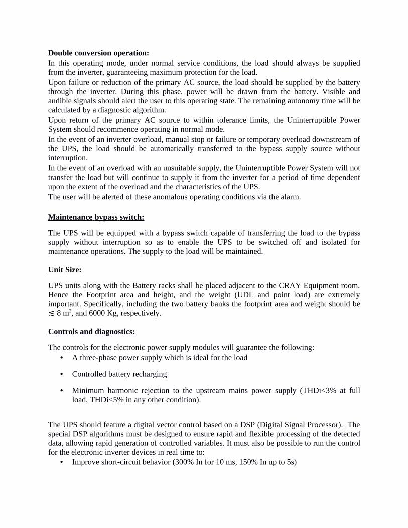
Double conversion operation: In this operating mode, under normal service conditions, the load should always be supplied from the inverter, guaranteeing maximum protection for the load.Upon failure or reduction of the primary AC source, the load should be supplied by the battery through the inverter. During this phase, power will be drawn from the battery. Visible and audible signals should alert the user to this operating state. The remaining autonomy time will be calculated by a diagnostic algorithm.Upon return of the primary AC source to within tolerance limits, the Uninterruptible Power System should recommence operating in normal mode.In the event of an inverter overload, manual stop or failure or temporary overload downstream of the UPS, the load should be automatically transferred to the bypass supply source without interruption.In the event of an overload with an unsuitable supply, the Uninterruptible Power System will not transfer the load but will continue to supply it from the inverter for a period of time dependent upon the extent of the overload and the characteristics of the UPS.The user will be alerted of these anomalous operating conditions via the alarm.
Maintenance bypass switch:
The UPS will be equipped with a bypass switch capable of transferring the load to the bypass supply without interruption so as to enable the UPS to be switched off and isolated for maintenance operations. The supply to the load will be maintained.
Unit Size:
UPS units along with the Battery racks shall be placed adjacent to the CRAY Equipment room. Hence the Footprint area and height, and the weight (UDL and point load) are extremely important. Specifically, including the two battery banks the footprint area and weight should be ≲ 8 m2, and 6000 Kg, respectively.
Controls and diagnostics:
The controls for the electronic power supply modules will guarantee the following:• A three-phase power supply which is ideal for the load
• Controlled battery recharging
• Minimum harmonic rejection to the upstream mains power supply (THDi<3% at full load, THDi<5% in any other condition).
The UPS should feature a digital vector control based on a DSP (Digital Signal Processor). The special DSP algorithms must be designed to ensure rapid and flexible processing of the detected data, allowing rapid generation of controlled variables. It must also be possible to run the control for the electronic inverter devices in real time to:
• Improve short-circuit behavior (300% In for 10 ms, 150% In up to 5s)

• Have a synchronized (precise phase) angle between UPS output and bypass network, in the event of mains voltage distortion
• Highly flexible parallel operation.
Microprocessor control and diagnostics:
Operation and control of the UPS should be provided through the use of micrroprocessor-controlled logic. Indications, measurements and alarms, together with battery autonomy, should be shown on a graphic liquid crystal display (LCD). The procedures for start up, shutdown and manual transfer of the load to and from bypass should be explained in clear step-by-step sequences on the LCD display.Warning/fault: This page should contain information regarding various anomalies concerning power converters such as the bypass, rectifier, inverter and booster/charger. In addition to this there should be warning and fault information relating to the battery and the load.
Events log: To displays the date and time of important UPS events, alarms and other warnings.
Measurements: This page should hold the full set of measurements for each functional block (rectifier, bypass, booster/charger, batteries, inverter and load).
Battery: Should displays the battery status/values including temperature, cell voltage, capacity and run time as well as commands for allowing the user to configure battery testing.
Tools: This page should allow users to customize the settings of the LCD display and to select the desired language.
Controls:
The UPS will be provided with the following controls:• Inverter start
• Inverter stop
• Reset faults
• Buzzer/mute alarm
Measurements:
The UPS should provide the measurements (voltage, current and frequency) for every single internal functional block and this information will be directly accessible on the display, via the measurements button.
Signals and alarms: The UPS must provide signals and alarms for every single functional block. These signals must be directly accessible via the display, by clicking the warning and fault button.

The UPS should also:• Clearly display, upon mains failure, the remaining battery autonomy which will be a
function of battery status and charge (discharge curve, degradation, operating temperature, etc).
• Have three serial RS232 ports for compatibility and communications with special peripheral units and for remote connections.
• Be able to support remote graphic measurement and signaling software.• Have interface with a network monitoring system using SNMP slot-in cards compatible
with Linux.• Provide a telemonitoring function
A voltage-free input will also be provided to disable the static switches and all power converters (EPO) in case of emergency.Programmable I/O contacts (at least 4 voltage-free outputs and 2 inputs).
Monitoring and control : The system should be capable of analyzing UPS operation and electrical supply in order to identify faults and thus prevent the occurrence of conditions likely to damage the equipment protected by the UPS. The system should guarantee single or parallel UPS surveillance, 24 hours a day for 365 days a year by authorized technical personnel operating remotely. The system should provide a detailed, preventive analysis of connected UPS, without any of the disruption associated with an on-site visit. The telemonitoring system should offer the following main features:
• Continuous monitoring and control of the performance of end-user UPS.• Bi-directional communications between end-user UPS, Authorized Service Centre and its
authorized field service engineers.• Automatic location of Service Engineers in the event of anomalous UPS functioning (even
at night and during public holidays).• Possibility of using graphic software for remote in-depth analysis and control.• Periodic reports on UPS performance with advice from Service Centre engineers.
The whole UPS, Batteries, and accessories installation have to be done in tandem with the false floor and ceiling work at the site.
Warranty: At least two years on site comprehensive warranty followed by three years or more AMC (Annual Maintenance Contract) for UPS is required. For battery, two years warranty is required. Price should be quoted including the warranty and AMC. Service should be provided by the OEMs directly, and not by any other vendors/franchises.
Price & Payment: Price should be quoted for S. N. Bose National Centre for Basic Sciences, inclusive of warranty and AMC. The quotation once submitted will not be allowed to be withdrawn.The total award price for indigenous item will be released after supply,successful installation, testing, & commissioning of the system at the Centre and completion of all contractual obligations of the supplier.

MISCELLANEOUS PROVISIONS :
Authorized Business Distributor/Dealer shall be able to bid with MAF (Principal Manufacturer’s authorization certificate). Either the principal manufacturer or its only one exclusive authorized distributor/dealer is eligible to participate in the tender.This section defines details of services, activities and means necessary to complete the supply of the Uninterruptible Power System.The constructional and functional characteristics of UPS must be in line with the state-of-the-art technology in this field.The supplying company must be able to provide proof that it is ISO 9001-2000 and ISO 14001 certified for design and manufacturing and for the provision of services.The UPS will be guaranteed for trouble free operation for one year during which time the Supplier will provide technical assistance.The offer must include:
• A draft maintenance contract providing for 24 hour service with guaranteed minimum service call response time of 4 hours.
• The addresses of all Service Centres, divided according to geographical areas, and the number of engineers working for each centre.
• Indication of main tele-monitoring installations in operation.Documentation:All technical documents issued by the supplier, in particular the user handbook and the installation, maintenance and troubleshooting guides must be in English.Spare parts: The supplier may include a list of recommended spare parts along with the technical bid for at least five years.Packaging:The supplier will ensure that all equipment is suitably packaged.Shipment:The supplier should ensure that the equipment is shipped to the specified address on the agreed date.Quality Assurance, Inspection and Testing: The units should be manufactured and tested as per approved Quality Assurance Plan.Inspection and Testing: The tenderer shall include and provide in the offer all facilities, which shall enable inspection by the purchaser at tenderer’s premises/factory.The inspection by the purchaser shall not relieve the tenderer of liability for rectification of any defects, which may subsequently appear or be detected during and after commissioning. The successful tenderer shall rectify all such defects without any extra cost to the purchaser. Materials shall be dispatched only after getting the clearance from the purchaser. Test certificates for the equipment shall be provided by the tenderer.Factory Testing: Before shipment, the manufacturer shall fully and completely test the system to ensure compliance with the specification and as per prevalent national and international standards viz. IEC 62040-3.

Factory Acceptance Test: The tenderer shall carry out Factory Acceptance Test (FAT) on the system to establish functioning of the system as whole and independent equipment as part of the system.The following Tests to be conducted during FAT for each 160 KVA UPS unit
1. Checking various electrical parameters on UPS display panel and monitoring input/output voltage, current, frequency, power, battery voltage, battery charging current etc.
2. Operation of static bypass switch.3. System performance under change-over condition from mains to battery and vice-versa4. Parallel redundant system operation.5. Stable operation at No load for 48 hrs.6. Various protection features of the system.7. Interfacing & monitoring of UPS & PC with SNMP/LAN/Web management software.8. Any other tests that may be desired for successful operation of UPS system.
Final Acceptance T est: Final Acceptance test shall be carried out after installation, testing of all equipment, submission of all drawings, documents, operation and service manual. Commissioning:Commissioning costs will be payable by the Supplier who will be responsible for the work done and the personnel involved.Technical personnel will be trained to meet the requirements of current work safety standards.Training:The purchaser intends that a maximum of four technical personnel shall be trained in operation and maintenance of the UPS system at tenderer site/manufacturer works in Kolkata, India. The successful tenderer shall make arrangement for their training for a period of five working days of the system to the purchaser. The to and fro travel charges, boarding and lodging of the persons deputed for training shall be borne by the purchaser.Service hot line: The supplier shall indicate the service centre nearest to the place of installation of the equipment supplied under the contract. The service centre indicated must be able to provide routine maintenance services and must be able to respond urgent calls at the terms and conditions specified. Bidder ’ s qualification criteria:
• Manufacturer/OEM should have experience in manufacturing & installation of UPS in India for last 10 (Ten) years;
• Manufacturer should have ISO 9001, ISO 14001 Certification;
• Manufacturer should have installation base in the respective location for such Units and fully equipped Service center to give prompt & efficient service; Reporting time shall be less than 2 Hours and Resolution time within 4 Hours. Provide reference/escalation matrix. The declaration should be supported by at least two end users of similar systems.
• Manufacturer/OEM should have minimum 10 nos of Installations base of UPS with same capacity (160kVA) or more with proposed model.

• All certificates mentioned above should be furnished along with the technical bid.
• Authorized Business Distributor/Dealer shall be able to bid with MAF (Manufacturer authorization form). Either the principal manufacturer or its only one exclusive authorized distributor/dealer is eligible to participate in the tender.
General Instructions for Vendors1. Vendor must design and quote two number of units of Uninterrupted Power Supply
(UPS) systems with redundancy to meet their proposed design. They also need to provide a detail calculations on their rational of the proposed solution.
2. Vendors shall provide weight and dimensions for each units of UPS including batteries.
3. Any deviations or exceptions to the minimum requirements must be clearly stated in the offer in a separate sheet under the head “ Deviation from the technical specifications”.
4. Incomplete & conditional tenders and tenders received after due date will be summarily rejected without assigning any reasons thereof.
5. Tender submitted shall remain valid at least for three months. Validity beyond three months from the date of opening the tender will be under mutual consent.
6. Tender should accompany technical compliance sheet.
7. The rate should be inclusive of all taxes, transportation etc. Nothing extra will be paid in addition to the quoted rate. The price should be quoted with out excise duty & custom duty as the Centre is exempted from payment excise & custom duty.
8. Proposed delivery schedule should be mentioned specifically. The delivery, installation, testing, and commissioning of the system should be completed within 10 weeks of time from the issue date of purchase order.
9. Warranty certificates, user manuals etc. Are to be handed over to the user after successful installation & commissioning.
10. The institute shall not be responsible for any delay, loss, or non-receipt of the tender through post.
11. The tender is being issued with no financial commitment, and purchaser reserves the right to change/vary any item or items thereof at any stage.
12. No tenderer shall be entitled for any compensation what so ever for rejection/non consideration of this tender.
13. Invitation of tender does not constitute any right or claim for the issue of purchase order to the tenderer.
14. Only price bids will be opened in presence of the bidders or their authorized representatives, who chose to attend on the date and time informed to them after opening of technical bids and evaluation. The technical bids will be opened internally and
evaluated by the technical committee and if required clarifications will be obtained through email, fax, phone etc. From the tenderer.
15. The Centre is not responsible for any misprint by the newspapers.
16. In case of any dispute, the decision of the competent authority of the Centre shall be final and binding on the bidders. Jurisdiction for any dispute shall be in kolkata.
17. For any clarification contact Dr. Amitava Moitra at [email protected].
18. The decision of the technical committee is final and incontrovertible regarding the qualification of the technical bids.
Quantity Required: 01 no.

Technical Specification For Item No. 02
The specifications constitute a call for best offers for the supply, installation, testing & commissioning of High Performance Precision direct expansion (DX) air-cooled, floor discharge type Air Condition (AC) units, suitable for the CRAY XE6 Super-computing system at the Centre. The purpose of this specification is to define minimum design, construction, and testing criteria relating to the supply of Precision AC.Design conditions: Air-conditioning system shall be designed for 24 hours operation with following specifications:
Ambient Air:Room Temperature: 20° ± 3°C Relative Humidity: 50% ± 5% non-condensing
Underfloor Air Temperature: 13°C ± 2°CRelative Humidity: 50% ± 5% non-condensing
Air flow : minimum 9000 cfm (4.26 m3/s) Allowed Dust Content: ~5 Microns Other Specifications:
1. The capacity of CRAY Equipment, specified above, is actual capacity at operating condition during peak Summer. Bidder is requested to check and confirm the Capacity, before submission of the quotation. Bidder is requested to select the air-cooled condenser for 45º C ambient condition to avoid any deration during peak Summer condition.
2. Scheme: The air-conditioning system consists of Precision Packaged air-conditioners as indicated in the Equipment schedule above. Precision AC units shall be of Variable capacity type. The cold & de-humidified air shall be pumped into the space between true floor and false floor and fed to the CRAY equipment through the bottom and return shall be taken from top of the CRAY equipment.
3. The CRAY equipment room shall be air-conditioned with at least four (three + one redundant) Variable Capacity Precision Air-conditioning Unit each of at least 17 TR actual capacity in order to compensate the total estimated heat load of 175 kW. The air-conditioning unit shall be designed specifically for high sensible heat ratio (>0.90) applications.
4. The system shall contain steep-less variable capacity Scroll compressor (If compressor is variable frequency driven, Electromagnetic Interference filter need to incorporate) Evaporator blower (Backward curved Centrifugal Fan with Electronically Commutated Motor) & coil, Heater, Humidifier, Specific De-humidification cycle, Microprocessor & electrical and Expansion valve all of which shall be contained within the cabinet of the unit. The outdoor condenser unit shall be air-cooled type comprising of coil, fan, motor and fan speed controller.
The Technical specifications of the construction of unit are as follows:
The Precision Environmental Control Systems shall be of self contained factory assembled unit with down flow air delivery (Evaporator Fan shall be below false floor for better energy efficiency). The Precision Air conditioner shall be High sensible cooling capacity and high Sensible Heat Ratio (i.e. the sensible to total cooling capacity ratio)
Frame & Casing:
The frame shall be constructed of galvanized steel. The external panels shall be constructed of at least 1.2 mm zinc coated sheet steel. Front, rear and end panels shall be fitted with at least 25 mm glass fiber insulation, fire rated to Australian Standard. The cabinet shall be powder coated and have a texture finish. The hinged front panels shall be removable and include captive ¼ turn fasteners. The cabinet shall be assembled with pop rivets providing ease of dis-assembly.
Filter:
The filter chamber shall be an integral part of the system and withdrawable from the front of the unit. Filtration shall be provided by dry media disposable filters capable of filtering air to 95% down to 5 micron efficiency and shall be replaceable from the top of the unit. Filtration shall be provided by deep V form, dry disposable should be housed in a metal frame.
Evaporator Fan:
Units should be offered with backward curve direct drive fan, high efficiency, external rotor electronically commutated (EC) motor with integrated electronics, true soft start characteristics (inrush current lower than operating current), Backward curve, corrosion resistant aluminum fan wheel, Maintenance free design and construction. The fan section shall be designed for higher air flow. The unit shall be fitted with at least one direct-driven, high efficiency, single inlet, backward curved; the fan motors shall be Electronically Commutated (EC), with internal protection and speed regulation via controller signal. They shall be statically and dynamically balanced. (Evaporator Fan shall be below false floor for better energy efficiency)
Compressor:
One refrigeration circuit, incorporating a high efficiency, fully hermetic Variable Capacity Scroll Compressor with crankcase heater. The compressor shall be charged with R407C. The compressor solenoid valve shall unload the compressor & allow the variable capacity operation, i.e. the Scroll compressor shall modulate its capacity from 20% to 100% without frequency variation. Each compressor is equipped with pre-set high and low pressure switches for protection against high condensing and low evaporating temperatures. Each compressor should work in a power efficient mode, and shall have internal motor protection and be mounted on vibration isolators.
Refrigeration Circuit:
The refrigeration system shall be of the direct expansion type and incorporate one compressor, complete with crankcase heaters. The system shall include a manual reset high pressure control, auto reset low pressure switch, externally equalized expansion valve, high sensitivity refrigerant sight glass, large capacity filter drier and charging/access ports in each circuit. Each refrigeration

circuit shall include rigidly mounted isolation valves in the discharge and liquid lines to aid servicing and installation.
Evaporator Cooling Coil:
The evaporator coil shall be A-coil (for down flow) incorporating draw-through air design for uniform air distribution. The coil shall be constructed of rifled bore copper tubes and louvered aluminum fins, with the frame and drip tray fabricated from heavy gauge aluminum. All metal parts in contact with condensate shall be the same material to prevent electrolytic corrosion. The drip trays shall ensure the collection of condensate and be accessible for cleaning. The cooling shall be maximum of 4 rows and minimum 11 fins per inch and the face velocity shall not be more than 2.5m/s.
Remote Air-cooled Condenser:
The Air-cooled condenser shall be the low profile, weatherproof type incorporating high efficiency, direct drive, external rotor motors with axial blade fans & fan speed controller. The condenser shall be constructed from heavy duty aluminum and corrosion resistant through special anticorrosive epoxy coatings for any specific polluted areas. Heavy duty mounting legs and all assembly hardware shall be included. Condensers shall be suitable for 24 hours operation and be capable of providing vertical or horizontal discharge. The condenser shall be fully factory wired and require a 230 volt, single phase, 60 Hz electrical service. The high performance heat exchanger shall include mechanically expanded cross-hatched copper tubes and louvered aluminum fins for maximum heat transfer.
Humidifier:
The humidifier shall be of the infrared type consisting of high intensity quartz lamps mounted above and out of the water supply. The humidifier pan shall be stainless steel and arranged to be removable without disconnecting high voltage electrical connections. The complete humidifier section shall be pre-piped, ready for field connection to water supply. The humidifier shall be equipped with an automatic water supply system and shall have an adjustable water-overfeed to prevent mineral precipitation. A high-water detector shall shut down the humidifier to prevent overflowing.
Electrical Heating:
The electrical heating elements shall not operate at a level exceeding 60 W/Sq. m. The low watt density elements shall be of finned tubular construction. The heating circuit coil shall include dual safety protection through loss of air and high temperature controls. Electric heating shall be provided in a single stage. The elements shall be low watt density, 304 stainless steel fin tubular construction, protected by thermal safety switches. The heating system shall include dual safety protection through loss of air and manual reset high temperature controls.
Unit Size:
Precision AC Indoor units shall be placed inside the CRAY Equipment room only. Hence the footprint area (high kW to footprint area) and the height of the Unit, and the weight (UDL and point load) are extremely important to accommodate the same inside the existing Equipment Room. Specifically, the total indoor unit footprint area and weight should be ≲ 6 m2, and 2500 Kg, respectively. The unit shall require front access only for routine service and installation work.
Microprocessor Controller: The unit control shall be factory-set for Intelligent Control which uses "fuzzy logic" and "expert systems" methods. Proportional and Tunable PID shall also be user selectable options. Internal unit component control shall include the following:
• System Auto Restart
The auto restart feature will automatically restart the system after a power failure. Time delay shall be programmable.
• Sequential Load Activation
On initial startup or restart after power failure, each operational load is sequenced with a minimum of one second delay to minimize total inrush current.
• Predictive Humidity Control
Calculates the moisture content in the room and prevents unnecessary humidification and dehumidification cycles by responding to changes in dew point temperature. The control shall be compatible with all remote monitoring and control devices. Solution should be provided for Building Management Systems (BMS) interface via MODbus, BACNet and SNMP. The control processor shall be microprocessor based with a 128x64 or better dot matrix graphic front monitor display and control keys for user inputs mounted in an ergonomic, aesthetically pleasing housing. The controls shall be menu driven. The display & housing shall be viewable while the unit panels are open or closed. The display shall be organized into three main sections: User Menus, Service Menus and Advanced Menus. The system shall display user menus for: active alarms, event log, graphic data, unit view/status overview (including the monitoring of room conditions, operational status in % of each function, date and time), total run hours, various sensors, display setup and service contacts. A password shall be required to make system changes within the service menus. Service menus shall include: setpoints, standby settings (lead/lag), timers/ sleep mode, alarm setup, sensor calibration, maintenance/wellness settings, options setup, system/network setup, auxiliary boards and diagnostics/service mode. Another password shall be required to access the advanced menus.
• User Menus shall be defined as Follows:
Active AlarmsUnit memory shall hold at least 200 most recent alarms with time and date stamp for each alarm.

Event LogUnit memory shall hold at least 400 most recent events with event ID number, time and date stamp for each event.Graphic Data ViewTwo graphic records shall be available: return air temperature and return air humidityUnit View - Status OverviewSimple or Graphical. Unit View summary displays shall include temperature and humidity values, active functions (and percent of operation) and any alarms of the host unit.Total Run HoursMenu shall display accumulative component operating hours for major components including compressors, fan motor, humidifier and reheat.Microprocessors should be intelligent enough to do the following task:
• Save Energy using Predictive Humidity Control
• Built-in Lead/Lag Functions for enhanced system reliability
• Wellness Calculation alerts service personnel before problems occur
• Unit to Unit (U2U) Communications allows Lead/Lag and optional teamwork settings for maximum flexibility and control
• IntelliSlot cards to offer external monitoring through Modbus RTU and HTTP/SNMP protocols
• IntelliSlot SNMP protocols should be compatible with Linux
• The microprocessor shall activate an audible, visual and general alarm in the event of any of the following conditions:
• High Temperature• Low Temperature• High Humidity• Low Humidity• Loss of Air• High Pressure• Low Pressure• Humidifier Low Water• Water Under Floor• Spare Alarm 1 and 2 (Customized text)
The unit shall also incorporate the following protections:• Single phasing preventors.• Reverse phasing• Phase imbalancing• Phase failure
Overload tripping (MPCB) of all componentsStandby Settings/Lead-LagMenu shall allow planned rotation or emergency rotation of operating and standby units.
Timers/Sleep ModeMenu shall allow various customer settings for turning on/off unit.Teamwork Modes of OperationSaves energy by preventing operation of units in opposite modes multiple units.Auxiliary BoardsMenu shall allow setup of optional expansion boards.
Diagnostics/Service Mode: Control input and output values and status shall be displayed to aid in unit diagnostics and troubleshooting.Control inputs shall be indicated as on or off at the front display. Control outputs shall be able to be turned on or off from the front display without using jumpers or a service terminal. Each control output shall be indicated by an LED on a circuit board.The unit shall also incorporate the following protections:
1. Single phasing preventers.
2. Reverse phasing
3. Phase unbalancing
4. Phase failure
5. Overload tripping (MPCB) of all components
Safety Interlocks: Operation of heaters & humidifiers shall be possible only when blower fan is in operation.Fire detection signal from fire detector system shall be able to switch off the package unit operation in event of fire in conditioned space.
Refrigerant Piping: Each refrigerant circuit shall be suitable for operation on R-407C and shall include the following items:a) Expansion valve with pressure equalization
b) Removable liquid line drier / filter.
c) Liquid line sight glass with moisture indicator.
d) Hand shut off valves.
e) High quality Nitrile based insulation material.
Sequencing of Operation of Unit: The Precision AC units for the room shall be clubbed in individual group, so that Stand-by unit should start on after specific time of operation of working unit, as well as during break down of working unit. This sequencing operation feature should be integral part.
Electrical Work: Each Precision AC units should be provided with in-built electrical panel. Balance distribution of power is in the Scope of Bidder. All Electrical cabling should be of Copper. The minimum input power factor of the whole system should be 0.85.
The whole Precision AC, and accessories installation have to be done in tandem with the false floor and ceiling work at the site.
Warranty: At least two years comprehensive warranty followed by a three years or more AMC (Annual Maintenance Contract) for Precision AC is required. Price should be quoted including the warranty and AMC rate should be quoted seperatly. Service should be provided by the OEMs directly, and not by any other vendors/franchaises.
Bidder ’ s qualification criteria: • Manufacturer should have ISO 9001, ISO 14001 Certification;
• Manufacturer/OEM should have experience in manufacturing & installation of Precision AC units in India for last 10 (Ten) years;
• Manufacturer should have installation base at Kolkata for such Units and fully equipped Service center to give prompt & efficient service; Reporting time shall be less than 2 Hours and Resolution time within 4 Hours. Provide reference/escalation matrix. The declaration should be supported by at least two end users of similar systems.
• Manufacturer/OEM should have minimum 10 nos of Installations base of Precision Air-conditioning system capacity more than 50 TR throughout India.
• All certificates mentioned above including the installation certificates of the completed works should be furnished along with technical bid.
• Authorized Business Distributor/Dealer shall be able to bid with MAF (Manufacturer authorization form). Either the principal manufacturer or its only one exclusive authorized distributor/dealer is eligible to participate in the tender.
MISCELLANEOUS PROVISIONS :
Authorized Business Distributor/Dealer shall be able to bid with MAF (Manufacturer authorization form). Either the principal manufacturer or its only one exclusive authorized distributor/dealer is eligible to participate in the tender.
The supplying company must be able to provide proof that it is ISO 9001-2000 and ISO 14001 certified for design and manufacturing and for the provision of services.
The offer must include:• A draft maintenance contract providing for 24 hour service with guaranteed minimum
service call response time of 4 hours. Provide reference/escalation matrix.
• The addresses of all Service Centres, divided according to geographical areas, and the number of engineers working for each centre.
• Indication of main tele-monitoring installations in operation.
Documentation:
All technical documents issued by the supplier, in particular the user handbook and the installation, maintenance and troubleshooting guides must be in English.Spare parts:
The supplier may include a list of recommended spare parts in the offer for at least five years.
Packaging:
The supplier will ensure that all equipment is suitably packaged.
Shipment:
The supplier should ensure that the equipment is shipped to the specified address on the agreed date
Quality Assurance, Inspection and Testing:
The units should be manufactured and tested as per approved Quality Assurance Plan.
Inspection and Testing:
The tenderer shall include and provide in the offer all facilities, which shall enable inspection by the purchaser at tenderer’ premises/factory. The inspection by the purchaser shall not relieve the tenderer of liability for rectification of any defects, which may subsequently appear or be detected during and after commissioning. The successful tenderer shall rectify all such defects without any extra cost to the purchaser. Materials shall be dispatched only after getting the clearance from the purchaser. Test certificates for the equipment shall be provided by the tenderer.
Factory Testing:
Before shipment, the manufacturer shall fully and completely test the system to ensure compliance with the specification and as per prevalent national and international standards viz. IEC 62040-3.
Factory Acceptance Test:
The tenderer shall carry out Factory Acceptance Test (FAT) on the system to establish functioning of the system as whole and independent equipment as part of the system.The following Tests to be conducted during FAT for each unit of the Precision AC system:
1. Various protection features of the system.2. Parallel redundant system operation.3. Interfacing & monitoring of PAC & PC with SNMP/Web management software.4. Any other tests that may be desired for successful operation of PAC system.

Final Acceptance T est:
Final Acceptance test shall be carried out after installation, testing of all equipment, submission of all drawings, documents, operation and service manual.
Commissioning:
Commissioning costs will be payable by the Supplier who will be responsible for the work done and the personnel involved.Technical personnel will be trained to meet the requirements of current work safety standards.
Training:The purchaser intends that a maximum of four technical personnel shall be trained in operation and maintenance of the Precision AC system at tenderer site/manufacturer works in Kolkata, India. The successful tenderer shall make arrangement for their training for a period of five working days of the system to the purchaser.
Service hot line:
The supplier shall indicate the service centre nearest to the place of installation of the equipment supplied under the contract. The service centre indicated must be able to provide routine maintenance services and must be able to respond urgent calls at the terms and conditions specified.
General Instructions for Vendors1. Vendor must design and quote appropriate number of units of Precision Air Conditioning
(PAC) systems with redundancy to meet their proposed design. They also need to provide a detail calculations on their rational of the proposed solution.
2. Vendors shall provide weight and dimensions for each units of Precision AC including outdoor units.
3. Any deviations or exceptions to the stated requirements must be clearly stated in the offer in a separate sheet under the head “Deviation from technical specifications”.
4. Incomplete & conditional tenders and tenders received after due date will be summarily rejected without assigning any reasons thereof.
5. Tender submitted shall remain valid at least for three months. Validity beyond three months from the date of opening the tender will be under mutual consent.
6. Tender should accompany technical compliance sheet.
7. The rate should be inclusive of all taxes, transportation etc. Nothing extra will be paid in addition to the quoted rate. The price should be without excise/custom duty as the Centre is exempted from payment of excise/custom duty.

8. Proposed delivery schedule should be mentioned specifically. The delivery, installation, testing, and commissioning of the system should be completed within 10 weeks of time from the issue date of purchase order.
9. Warranty certificates, user manuals etc. Are to be handed over to the user after successful installation & commissioning.
10. The institute shall not be responsible for any delay, loss, or non-receipt of the tender through post.
11. The tender is being issued with no financial commitment, and purchaser reserves the right to change/vary any item or items thereof at any stage.
12. No tenderer shall be entitled for any compensation what so ever for rejection/non consideration of this tender.
13. Invitation of tender does not constitute any right or claim for theissue of purchase order to the tenderer.
14. Only price bids will be opened in presence of the bidders or their authorized representatives, who chose to attend on the date and time informed to them after opening of technical bids and evaluation. The technical bids will be opened internally and evaluated by the technical committee and if required clarifications will be obtained through email, fax, phone etc. From the tenderer.
15. The Centre is not responsible for any misprint by the newpapers.
16. In case of any dispute, the decision of the competent authority of the Centre shall be final and binding on the bidders. Jurisdiction for any dispute shall be in kolkata.
17. For any clarification contact Dr. Amitava Moitra at [email protected].
18. The decision of the technical committee is final and incontrovertible regarding the qualification of the technical bids.
Quantity Required: 01 no.