s modeling of p m - adapt software help · of the models. the balanced loading, primary actions,...
TRANSCRIPT

STRUCTURAL MODELING OF POSTTENSIONED MEMBERS
By Bijan O. Aalami1
INTRODUCTIONPrestressing is used to control crack formation in concrete,
reduce deflections, and add strength to the prestressed member.Prestressing thus plays a significant role in the structural integ-rity and desired response of the member.
The authenticity and relevance of the analysis of a pre-stressed concrete member rests, first and foremost, on appropri-ate modeling of the tendons. Several different modeling schemesare used to represent prestressing tendons, each of which hassome degree of approximation [Scordelis 1984]. This paper pro-vides a brief description of each scheme and places their com-parative features in perspective.
The focus of the paper is on the post-tensioning tendons.These are groups of prestressing strands, wires, or rods, whichare stressed against the concrete member after the concrete isset. The tendons are typically given a profile in the vertical planeto enhance their load resisting characteristics.
The contribution of a tendon to the response of the pre-stressed member depends on the stress in the tendon at bothservice and strength limit conditions, the tendon’s profile and itscross-sectional area. There has been little difficulty in represent-ing the tendon profile accurately in structural analysis. The chal-lenge facing the various modeling schemes has been the accu-rate determination and representation of the stress in the tendon,including immediate and long-term effects. Depending on thestructure, the validity of the overall analysis may depend uponthe inclusion of such effects into the model.
The most critical considerations in the structural modelingof post-tensioned tendons are:
Immediate Loss of Stress in TendonFig.1-a shows a post-tensioned tendon within a partially
displayed concrete member. When the tendon is pulled with aforce F
o at the stressing end, it will elongate.
The elongation will be resisted by friction between the strandand its sheathing or duct, however. As a result of this friction,there will be a drop in the force in the tendon with distance fromthe jacking end. The friction is composed of two effects: curva-
ABSTRACT: This state-of-the-art paper offers a comprehensive overview of the modeling techniques used for theanalysis of post-tensioned structures. The merits and limitations of each of the modeling schemes are discussedwithin a consistent and comparative framework. Several numerical examples are used to illustrate the tacit featuresof the models. The balanced loading, primary actions, hyperstatic (secondary) actions, and prestressing momentconcepts commonly used in the analysis of prestressed structures are revisited and clarified. The work concludeswith an example of the most recent modeling technology - the discrete modeling of tendons. The example illustratesthe calculation of long-term prestress losses as an integral part of the analysis as opposed to the traditionalapproach where long-term losses are computed independently from the solution.
ture friction which is a function of the tendon’s profile, and wobblefriction which is the result of minor horizontal or vertical devia-tions from the specified profile.
After they are stressed, the tendons are typically anchoredwith conical wedges. The strand retracts upon release and pullsthe wedges into the housing of the anchorage device; this forcesthe wedges together and locks the strand in place. The retrac-tion of the tendon results in an additional stress loss over ashort length of the tendon at the stressing end. This loss isillustrated by the difference between the jacking force and thefinal force at the left end of the force profile in Fig. 1-b.
Fig. 1-b shows the variation in force along the tendon. Ingeneral, the stress loss will depend on the tendon’s length, itsprofile, its friction characteristics, the design of its locking mecha-nism and the stressing force. The combined loss due to all ofthese effects is commonly referred to as the friction and seatingloss. The force profile will be similar for a tendon stressed at twoends; although there will be a seating loss at each end the totalloss due to friction will be less.
Elastic Shortening
Most prestressed members are reinforced with several ten-dons which are stressed and anchored one after another. Aseach tendon is stressed, the compression in the concrete mem-ber increases. The elastic shortening of the concrete due to theincrease in compressive stress causes a loss of prestressing forcein tendons which were previously stressed and anchored. Thestress loss in each tendon will depend on the total number of
FIG. 1. Loss of Prestressing due to Friction and Seating
1 Emeritus Prof., San Francisco State Univ., San Francisco, CA 94123;and Prin., ADAPT Corp., 1733 Woodside Rd., #220, Redwood City, CA94061 Note. Associate Editor: Julio Ramirez. Discussion open until July 1,2000. To extend the closing date one month, a written request must befiled with the ASCE Manager of Journals. The manuscript for this paperwas submitted for review and possible publication on April 29, 1999.This paper is part of the Journal of Structural Engineering, Vol. 126,No. 2, February, 2000. Ó ASCE, ISSN 0733-9445/00/0002-0157-0162/$8.00 + $.50 per page. Paper No. 20815

tendons in the concrete member and the sequence of stressingamong other factors.
Long-Term Losses
Long-term losses cause a reduction in tendon stress withtime. These losses are due to several factors:
· Relaxation of the prestressing steel: Prestressing tendonslose a fraction of their initial stress with time due to themetallurgical characteristics of the prestressing material.The loss in stress at any location along a tendon dependson the current value and duration of the stress at thatlocation.
· Shrinkage in concrete: A significant cause of prestress-ing loss is shrinkage shortening of the concrete whichhouses the tendon. This results in a corresponding short-ening of the tendon and thus a direct reduction in tendonstress. The reduced tendon stress slightly reduces therate and amount of stress loss due to relaxation of theprestressing steel.
· Creep in concrete: In grouted (bonded) post-tensioningsystems, there is strain compatibility between the tendonand the concrete. Creep strain in the concrete adjacent tothe tendon thus causes a decrease in tendon stress. Forunbonded tendons, the decrease in stress along the ten-dons due to creep of the concrete is generally a functionof the overall (average) precompression of the concretemember.
Change in Stress Due to Bending of the Memberunder Applied Loading
As with nonprestressed steel, the bending of a concretemember due to applied (dead and live) loading results in a changein stress of the prestressing tendons. The stress change forgrouted tendons is the same as that of any nonprestressed steellocated at the tendon position. The stress change due to bend-ing is usually not viewed as a stress loss since, in most cases,there is an increase in stress. For a rigorous evaluation of theaffected member, however, this change in stress must be ac-counted for, particularly when large deflections are anticipated.
TENDON MODELING
For structural analysis, the prestressing tendons can bemodeled either as a loading applied to the hosting member or asa component which resists the applied loading in conjunctionwith the hosting member. Techniques which model the tendonas applied loading include load balancing, modeling through pri-mary moments, and equivalent load through discretization of thetendon force.
Modeling of Tendon as Applied Loading
Simple Load Balancing
Load balancing, the method introduced by T. Y. Lin [1981] isthe simplest and most expedient method of modeling tendons. Itis the most commonly used method in building design and whenit is applied judiciously and its limitations are recognized, it is apowerful technique.
In its simplest form, load balancing can be applied under thefollowing conditions:
· The member is prismatic with no change in the position ofits centroidal axis.
· The tendon profile in each span can be approximated as asingle, continuous parabola.
· The change in stress along the length of the tendon issmall and does not affect the analysis. In other words, aneffective (average) force can be assumed for the tendon.
· The effect of axial loading due to prestressing and theflexure of the member due to prestressing are independentfrom one another (decoupled).
If the given conditions are met, the impact of a tendon, removedfrom its housing, can be approximated by uniform loads on eachspan, as illustrated in the example of Fig. 2.
For each span of length L the tendon’s upward force (wb) is
given by:
wb = 8Pa/L2
where P is the force in the tendon and a is the tendon’s drape (thedifference between the high and low points).
For the left span of Fig. 2, the drape is:
a = 0.5(400+700) – 60 = 470 mm
The upward force is thus:
wb= 8*1200*0.470/202 = 11.76 kN/m
The force of the tendon on the concrete is considered to balance(offset) a portion of the load on the member, hence the “loadbalancing” terminology. The loading from the removed tendon(Fig. 2-a) is in self-equilibrium with the reactions it causes at theend of each tendon parabola. The uniform tendon force and its
FIG. 2. Simple Load Balancing

associated concentrated loads are collectively referred to as thebalanced loading. The balanced loading is independent of thesupport conditions of the structural member. Additional infor-mation on load balancing is provided in [Aalami, 1990].
In practice, tendons can not be placed with sharp anglesover the supports as shown in 2.1.1-1 (a). A gradual curvature,as illustrated in 2.1.1-1(c), is the common selection. Tendon lowpoints are at pre-determined locations (mid-span in most build-ing construction) and there is a gradual reversed curvature overthe supports. The force imparted by a tendon to the concretethus becomes more complex and less amenable to hand calcula-tion. This refinement in simple load balancing is used primarily inassociation with automated (computer) analysis.The principal shortcoming of the simple load balancing model-ing procedure is that it does not apply to members whosecentroidal axis changes along their length, such as members withdifferences in thickness, or steps. The other shortcoming is thatthe immediate and long-term stress losses in prestressing mustbe approximated and accounted for separately.
Extended Load Balancice
Consider the two-span beam shown in Fig. 3. Because thetwo spans are different depths, the tendon ends on either end ofthe beam are not aligned. In order to decouple the axial andflexural actions, in accordance with the load balancing concept,it is necessary to add a moment at the point at which the centroidalaxis shifts i.e. over the central support. This is shown in 2.1.2-1(b) and is described in more detail in [Aalami, 1990]. Since thisapproach assumes a constant effective force, the added momentis simply 1200*0.15 = 180kNm where 0.15m is the distance be-tween the centroids of the two spans.
The principal advantage of the extended load balancing ap-proach is its ability to account for nonprismatic members. Itdoes not include a calculation of the prestressing losses.
Tendon Modeling Through Primary Moments
The primary moment, Mp, due to the prestressing force, P,at any location along a member is defined as the prestressingforce times its eccentricity, e.
Mp = P *e
The eccentricity of the force is the distance between theresultant of the tendon force and the centroid of the member. Forthe example shown in Fig. 4, the moment at the right end of thefirst span is:
Mp = 1200 (400-100)/1000 = 360 kNm
The primary moment can be used as an applied loading inlieu of the balanced loading for structural analysis. This model-ing technique is more commonly used by bridge designers thanbuilding designers. It has the advantage of implicitly accountingfor nonprismatic sections – a condition which is common in bridgeconstruction. An added advantages is that by considering theprimary moment at each section to be the duly adjusted force atthat section times the eccentricity at the section, prestress lossesalong the tendon can be included. Note that if this option isadopted, the axial component of the prestress loading must be
FIG. 3. Extended Load Balancing (Note: Value in mm UnlessNoted Otherwise)
FIG. 4. Modeling through Primary Moments
FIG. 5. Discretization and Application of Primary Momentsas Loading

represented in its variable form to maintain an equilibrium offorces.
The primary moment, whether or not is adjusted for prestresslosses, depends only on the force in the tendon, the tendonprofile and the cross-sectional geometry of member. It is inde-pendent of the number and location of member supports or thesupport conditions.
In practice, the primary moment diagram is discretized into anumber of steps as illustrated schematically in Fig. 5. Each dis-crete moment shown in part (b) of the figure is equal to thechange in the value of moment between two adjacent steps inthe primary moment diagram. Note that the change of momentdue to the shift in the centroidal axis (M
5) is automatically ac-
counted for.For the example shown
M1 + M
2 = 408 kNm
Equivalent Load Through Discretization of Tendon Force
In this modeling scheme, the tendon force is discretizedalong its length to achieve the following improvements in accu-racy:
· The method accounts for the variation of force along thetendon length caused by the friction and seating of thetendon at stressing.
· The method accounts for losses in prestressing due tocreep and shrinkage using an approximate procedure.
Consider a span of a continuous member and its prestress-ing as shown in Fig. 6. The tendon length is idealized as a seriesof straight line segments, typically 20 segments per span. Fig. 7shows a portion of the discretized tendon. The actual distribu-tion of prestressing force is the smooth curve marked “actual” inpart (b) of the figure. For a tendon idealized as a series of straightsegments there is a gradual stress loss along each segment dueto wobble friction. The component of friction due to curvature(angle change), however, is concentrated at the intersection ofthe segments (marked as node i, i+1, …). Hence the force distri-bution would be represented by a series of sloping lines withsteps at the discretization points as shown in part (b). The forcedistribution can be further simplified by considering the force ineach tendon segment to be equal to the force at the mid-point ofthe segments, as shown in part (c).
For a representative tendon node i, the tendon forces of theadjacent segments are F
i and F
i-1, as shown in Fig. 8. The two
segment forces can be resolved into equivalent forces Fxi and
Fyi, parallel and perpendicular to the centroidal axis of the host-
ing member. These two force components can be transferred tothe centroid of the section with the addition of a moment, M
i,
equal to Fxi*e, where e is the eccentricity of the tendon at tendon
node i. Fig. 9 illustrates a series of equivalent tendon actionsplaced at the member centroid using this method.
This scheme, an iterative solution strategy which involvesthe coupling of the tendon force and its equivalent loading, re-sults in an analysis in which immediate prestress losses can berigorously accounted for and long term losses can be approxi-
mated. At each iteration the prestress losses are computed onthe basis of the current prestressing force. The current force isthen used to compute the equivalent forces, which will, in turn,change the long-term losses. The iteration is continued until con-vergence is achieved [ADAPT-PT, 1999].
Modeling of Tendon as a Load Resisting Element
Unlike the modeling schemes described in the previous sec-tions, when the tendon is modeled as a load resisting element, itis not considered as removed from the concrete member. Rather,the tendon is modeled as a distinct element linked to the concretemember. One other characteristic of this approach is that theallowance for long-term stress loss becomes an implicit featureof the computations. Separate stress loss computations are notrequired.
FIG. 6. Tendon Presentation by Discretization
FIG. 7. Idealization of Tendon Force

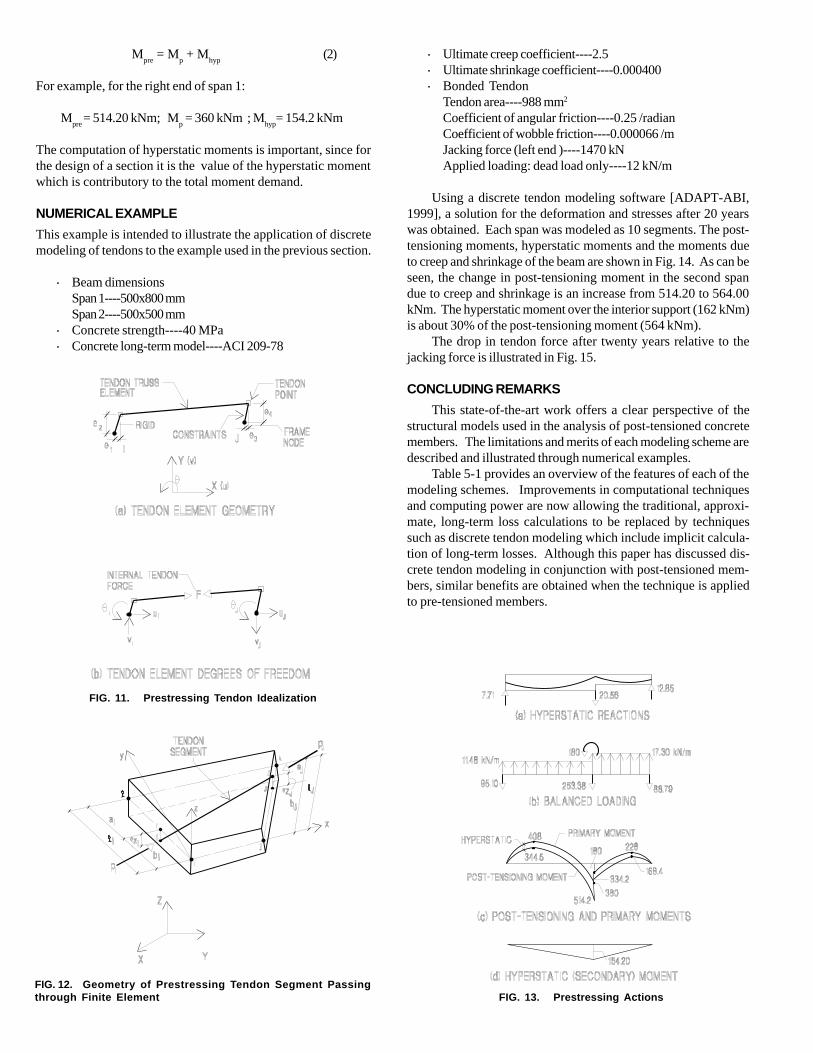
This modeling scheme is the core of analysis software suchas ADAPT-ABI [1999]. A similar modeling scheme can be ap-plied to three dimensional problems such as floor slabs and bridgedecks where the constituent elements of the slab can be viewedas consisting of concrete plate elements with embedded pre-stressing tendon elements (Fig. 12).
HYPERSTATIC (SECONDARY) ACTIONS
The structural modeling and analysis of prestressed mem-bers is not complete unless the hyperstatic (secondary) actionscaused by prestressing are considered. Hyperstatic actions arethe forces and moments generated in the member as a result ofconstraint by the member’s supports to free deformation of themember. Consider an extension of the example of Fig. 3 in Fig. 13.When the balanced loading shown in part (b) of the figure isapplied to the structure, the supports constrain the deformationof the structure. As a result, the forces at the supports shown inpart (a) are generated. These reactions are referred to as hyper-static (secondary) actions. They are in self-equilibrium, and arein response to the application of the balanced loading, which isalso in self-equilibrium. The hyperstatic reactions cause a distri-bution of moment in the structure (hyperstatic moments) asshown in part (d).As the terminology implies, hyperstatic moments are character-istic of indeterminate structures. The application of balancedloading to a structure results in prestressing (post-tensioning)moments. In an indeterminate structure, the prestressing (post-tensioning) moments (M
pre) are the sum of the primary (M
p) and
hyperstatic (Mhyp
) moments.
FIG. 8. Resolution of Tendon Actions at Discretization Points
Fig. 10, which shows a partial elevation of a bridge deck, isused to illustrate the modeling. For simplicity, only one prestress-ing tendon is shown. Before describing the discrete tendon mod-eling option however, the equivalent load tendon modeling isreviewed.
Parts (b), (d) and (f) of the figure illustrate the representationof a tendon by means of equivalent loading. Note that the ten-don is considered removed from its housing. The initial forcesimparted by the tendon to the segment are transferred to thecentroid of the segment (part d). These forces are considered asa constant applied loading which is not affected by creep, shrink-age, or deformation of the segment. Long-term loss effects areaccounted for at a later stage.
In contrast, in the discrete tendon modeling scheme, thetendon is retained in position (Fig. 10-c). Each tendon in thesegment is viewed as an independent element, subject to dis-placement and change in stress based on the deformation of thesegment within which it is housed, or to which it is locked (exter-nal tendons). Each tendon element is assumed to have an initialforce which is determined from friction loss calculations. Anysubsequent deformation of the concrete segment, such as shownin (g), will be accompanied by a compatible displacement of thetendon element, using the requirement of plane sections remain-ing plane (Fig. 11). The displacement of the tendon ends at thefaces of the hosting concrete segment results in a change intendon force.
Observe that in this modeling scheme there is an implicitinteraction between the deformation of the hosting concrete seg-ment and the force in tendon, irrespective of the cause of thedeformation. As a result, it is not necessary to calculate the de-formations due to creep and shrinkage separately in order tomodify the tendon force. Likewise, the change in prestressingforce due to relaxation is automatically accounted for in the equi-librium equations set up for the analysis of the segment.
FIG. 9. Equivalent Tendon Actions at Centroidal Axes
FIG. 10. Equivalent Load and Discrete Modelings
Mpre
= Mp + M
hyp(2)
For example, for the right end of span 1:
Mpre
= 514.20 kNm; Mp = 360 kNm ; M
hyp= 154.2 kNm
The computation of hyperstatic moments is important, since forthe design of a section it is the value of the hyperstatic momentwhich is contributory to the total moment demand.
NUMERICAL EXAMPLE
This example is intended to illustrate the application of discretemodeling of tendons to the example used in the previous section.
· Beam dimensionsSpan 1----500x800 mmSpan 2----500x500 mm
· Concrete strength----40 MPa· Concrete long-term model----ACI 209-78
· Ultimate creep coefficient----2.5· Ultimate shrinkage coefficient----0.000400· Bonded Tendon
Tendon area----988 mm2
Coefficient of angular friction----0.25 /radianCoefficient of wobble friction----0.000066 /mJacking force (left end )----1470 kNApplied loading: dead load only----12 kN/m
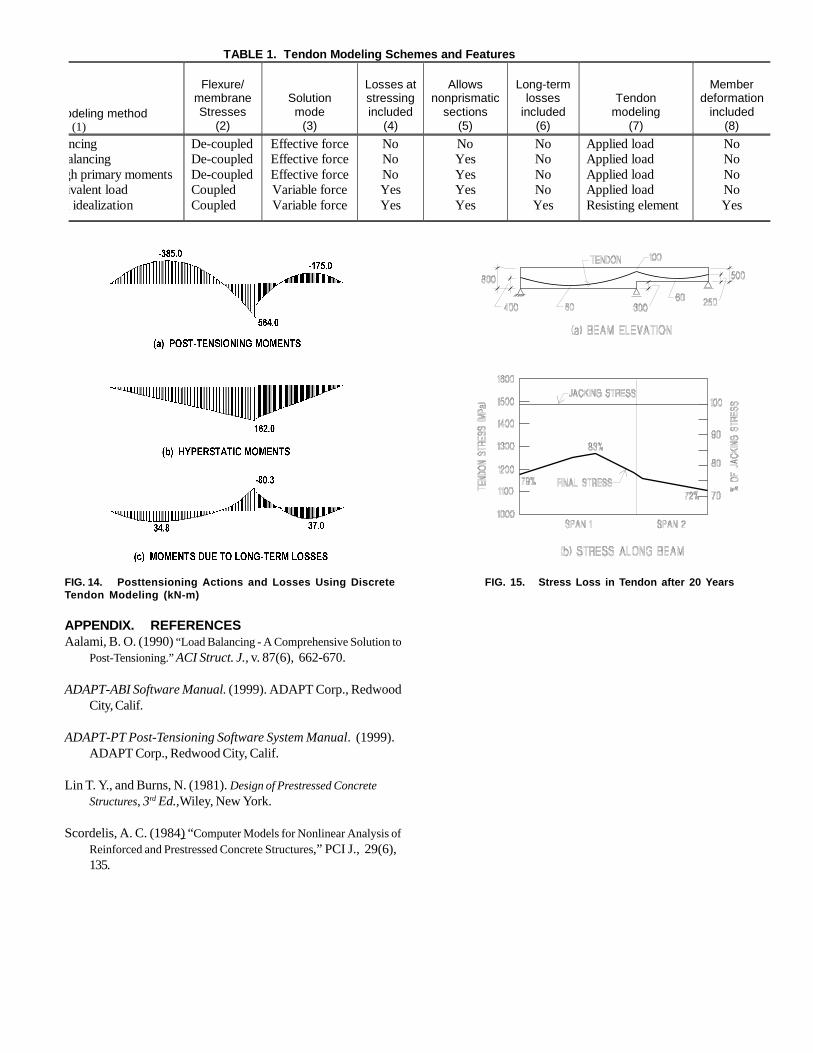
Using a discrete tendon modeling software [ADAPT-ABI,1999], a solution for the deformation and stresses after 20 yearswas obtained. Each span was modeled as 10 segments. The post-tensioning moments, hyperstatic moments and the moments dueto creep and shrinkage of the beam are shown in Fig. 14. As can beseen, the change in post-tensioning moment in the second spandue to creep and shrinkage is an increase from 514.20 to 564.00kNm. The hyperstatic moment over the interior support (162 kNm)is about 30% of the post-tensioning moment (564 kNm).
The drop in tendon force after twenty years relative to thejacking force is illustrated in Fig. 15.
CONCLUDING REMARKS
This state-of-the-art work offers a clear perspective of thestructural models used in the analysis of post-tensioned concretemembers. The limitations and merits of each modeling scheme aredescribed and illustrated through numerical examples.
Table 5-1 provides an overview of the features of each of themodeling schemes. Improvements in computational techniquesand computing power are now allowing the traditional, approxi-mate, long-term loss calculations to be replaced by techniquessuch as discrete tendon modeling which include implicit calcula-tion of long-term losses. Although this paper has discussed dis-crete tendon modeling in conjunction with post-tensioned mem-bers, similar benefits are obtained when the technique is appliedto pre-tensioned members.
FIG. 11. Prestressing Tendon Idealization
FIG. 12. Geometry of Prestressing Tendon Segment Passingthrough Finite Element FIG. 13. Prestressing Actions
APPENDIX. REFERENCESAalami, B. O. (1990) “Load Balancing - A Comprehensive Solution to
Post-Tensioning.” ACI Struct. J., v. 87(6), 662-670.
ADAPT-ABI Software Manual. (1999). ADAPT Corp., RedwoodCity, Calif.
ADAPT-PT Post-Tensioning Software System Manual. (1999).ADAPT Corp., Redwood City, Calif.
Lin T. Y., and Burns, N. (1981). Design of Prestressed ConcreteStructures, 3rd Ed.,Wiley, New York.
Scordelis, A. C. (1984) “Computer Models for Nonlinear Analysis ofReinforced and Prestressed Concrete Structures,” PCI J., 29(6),135.
TABLE 1. Tendon Modeling Schemes and Features
odeling method (1)
Flexure/
membrane Stresses
(2)
Solution mode
(3)
Losses at stressing included
(4)
Allows
nonprismatic sections
(5)
Long-term
losses included
(6)
Tendon modeling
(7)
Member
deformation included
(8)
ncing alancing gh primary moments ivalent load
n idealization
De-coupled De-coupled De-coupled Coupled Coupled
Effective force Effective force Effective force Variable force Variable force
No No No Yes Yes
No Yes Yes Yes Yes
No No No No Yes
Applied load Applied load Applied load Applied load Resisting element
No No No No Yes
FIG. 15. Stress Loss in Tendon after 20 YearsFIG. 14. Posttensioning Actions and Losses Using DiscreteTendon Modeling (kN-m)

This Page Left Intentionally
BLANK