s. l. painter j. lyo
TRANSCRIPT
3 4456 0334514 b -117
f
S. L. Painter J. E Lyo

-. . . . . . . . . . . . . . . . . . . . . . . . . . . . . .. '. ... . ... .. ............ ._..__ _...,,

ORNL/TM-11756 Dist. Category UC-426
Fusion Energy Division
TRANSPORT ANALYSIS OF STELLARATOR REACTORS
S. L. Painter*,t J. F. Lyon
Date published-February 1991
Prepared for submission to Nuclear f i s h
*Nuclear Engineering Department, The University of Tennessee, Knoxville.
t Permanent address: Research School of Physical Sciences, Australian National University, P.O. Box 4, Canberra, A.C.T. 2601, Australia.
Prepared for the Office of Fusion Energy
under Budget Activity No. AT 10 10 15 B
Prepared by the OAK RIDGE NATIONAL LABORATORY
Oak Ridge, Tennessee 37831-6285 managed by
MARTIN MARIETTA ENERGY SYSTEMS, INC. for the
U.S. DEPARTMENT OF ENERGY MARTIN MAPIETTA ENERGY EYblEMS LIBRAPI'S
under contract D E-AC05-840R2 1400
3 4 4 5 b 0334514 b


CONTENTS
ABSTRACT . . . . . . . . . . . . . . . . . . . . . . . . . . . . . v 1 . INTRODUCTION . . . . . . . . . . . . . . . . . . . . . . . . . 1 2 . PREVIOUS STELLARATOR REACTOR TRANSPORT STUDIES . . . 2 3.APPROACH . . . . . . . . . . . . . . . . . . . . . . . . . . . 4 4 . ELECTRON-ROOT AND ION-ROOT OPERATION . . . . . . . . . 9
4.1 Role of the radial electric field . . . . . . . . . . . . . . . . . 9 4.2 Electron-root operation . . . . . . . . . . . . . . . . . . . . 11 4.3 Ion-root operation . . . . . . . . . . . . . . . . . . . . . . 13 4.4 Sensitivity to the magnitude of the electric field . . . . . . . . . . 18
5 . EFFECT OF ALPHA-PARTICLE LOSSES . . . . . . . . . . . . . 20 6 . SENSITIVITY TO DEVICE PARAMETERS
AND ASSUMPTIONS . . . . . . . . . . . . . . . . . . . . . . . 22 6.1 Device parameter sensitivity . . . . . . . . . . . . . . . . . . 22 6.2 Sensitivity to profile assumptions . . . . . . . . . . . . . . . . 24 6.3 Sensitivity to anomalous transport . . . . . . . . . . . . . . . 26
7 . RESULTS WITH AN EMPIRICAL TRANSPORT SCALING . . . . . 27 8 . OPERATION WITH D-3He . . . . . . . . . . . . . . . . . . . . 30 9 . IMPLICATIONS FOR STELLARATOR REACTORS . . . . . . . . . 33
L4ppendix A . THE COLTRANE TRANSPORT CODE . . . . . . . . . . 37 Appendix B . ESTIMATES OF THE AMBIPOLAR ELECTRIC FIELD . . . 39 A4CKNOTVLEDGMENTS . . . . . . . . . . . . . . . . . . . . . . . 42 REFERENCES . . . . . . . . . . . . . . . . . . . . . . . . . . . . 43
... 111


ABSTRACT
The performance of deuterium-tritium stellarator reactors is studied with a
new, fast one-dimensional (1-D) transport survey code that is based on the spectral
collocation method. Two operating modes with different signs of the assumed radial
electric field are identified. The operating mode with a positive electric field is
characterized by high temperatures and moderate densities, whereas the other inode
has lower ternperatures and higher densities. Both modes lead to possible reactors
that could tolerate a large alpha-particle energy loss. The sensitivity to device
parameters and to profile assumptions is cxamined. Scaling expressions useful for
parametric studies are obtained for different quantities of interest, and the 1-D
code results are compared with results derived from an empirical scaling relation.
Deuterium-helium-3 ( D3He) operation is also feasible but is more demanding. The
implications for stellarat or reactor design optimization are discussed.
V


1. INTRODUCTION
Studies of stellarator reactors have become more relevant as improvements in
toroidal physics understanding have led to optimization of stellarator concepts
[l], new experiments have started operation [2], design studies of new large next-
generation stellarators have begun [3], and the potential limitations of tokamaks
as reactors have become more appreciated [4]. Stellarators offer the possibility of
ignited, steady-state fusion reactors without the need for current drive or pulsed
loads, or the danger of current-driven disruptions. Modern stellarator reactor
designs [l, 5 , 61 have high beta capability (volume-average beta (p ) > &lo%)
and feasible coil designs and maintenance schemes. Torsatron configurations also
have a naturally occuring bundle of diverted field lines that channels particles to
the region outside the main coils and simplifies the design of the power and particle
collection systems.
Adequate confinement is probably the key issue for stellarator reactors. It is
a potential concern because of the combination of the inherent non-axisymmetry,
which leads to a population of particles trapped in the helical modulation of the
magnetic field, and the poloidal variation of the magnetic field inherent in toroidal
devices, which causes the helically trapped particles to drift radially. Direct loss of
helically trapped alpha particles can occur and the diffusive heat loss associated with
helically trapped thermal particles can be large, unless measures are taken to reduce
these losses. The thermal losses can be reduced by radial electric fields that develop
to ensure quasi-neutrality by modifying, through E x B poloidal orbit rotation, the
otherwise non-ambipolar neoclassical losses of helically trapped particles [TI . Both
alpha-particle losses and thermal losses can be reduced by magnetic configuration
optimizations that reduce the effective helical ripple or increase the effective plasma
aspect ratio [8, 91. This paper exansines stellarator reactors with regard to these
losses and assesses the acceptable limits on the neoclassical (and anomalous) losses
for low-aspect-ratio rcactors (in particular, for A, EE &/a , - 5) for a range of
assumptions. Here Ro is the major radius and u p is the average radius of these
non-circular (and non-axisyrnmetric) plasmas.
Low-aspect-ratio reactors were chosen to assess the effect of helical-ripple-
induced losses on stellarator reactor performance because the coinbination of low
aspect ratio and large helical ripple in these devices enhances these losscs. Also, a
particular type of these devices, the Compact Torsatrons [lo], has attractive physics
properties (high beta capability in the second stability regime) and attractive
1

2
reactor properties (excellent access €or blankets and maintenance), and such devices
lead to reactors that are one-third to one-half the size of other stellarator reactors
[SI. Although configuration parameters similar to those of Compact Torsatrons
are used for specific examples, the treatment and conclusions apply in general to
stellarator reactors. Specific results applying to Advanced Stellarators are also
noted. Previous stiidies of stellara,tor reactors are summarized briefly in Section 2.
Section 3 discusses the approach used in our studies. The two modes of operation
obtained, which depend on the sign of the radial electric field, are described in
Section 4. Section 5 discusses the impact of alpha-particle losses on the two modes
of operation. The sensitivity of reactor performance to device parameters, profiles,
and other assuiriptions is disciissed in Section 6, and scalings for various quantities of
interest are obtained and compared with scalings obtained from simple arguments.
Section 7 describes the results obtained when an empirical global confinement
scaling relation is used instead of the more complete transport description. Rcactors
using B 3 H e are discussed in Section 8. Finally, Section 9 discusses implications for
future stellarator reactor optimization. Appendices give more detailed information
on the one-dimensional (1-U) transport code and estimates of the neoclassical
amhipolar electric field,
2. PREVIOUS STELLARATOR REACTOR
TRANSPORT STUDIES
Studies of stellarator reactors [I, 111 are not as extensive as those of tokamak
reactors. In particular, engineering features of stellarator reactors and global models
for energy confinement have been given more attention than have assessments of
reactor performance based on the more complete l -D transport equations, and
point designs have generally been emphasized over scoping studies. Studies of the
Heliotron H ( A , 2 11.7) reactor [12] used fixed temperature and density profiles
and assumed central values to calculate the total power output and the neutron
wall loading. These stiidies were extended to lower aspect ratio (A , = 8) in the
Bcliotron I study [13], again with fixed plasma profiles and assumed pararnelcrs.
The Modular Stellarator Reactor studies [14] analysed the paranietric dependences
of modular stellarator reactors for .4, = 11-28 but assumed a tokamak (Alcator)
scaling to obtain a global energy coifineirient time. Studies at the Kharkov
Institute of Physics and 'I'echnology of the U-2M R reactor (A , = 9.4) [15]
3
used an elec tric-field-dependent expression for the neoclassical fluxes derived by
Kovrizhnykh [16] to estimate a global energy confinement time and hence the
reactor parameters. Hitchon [17] has analysed low-aspect-ratio stellarator reactors
by developing approximate analytic expressions relating magnetic configuration
properties to parameters describing the shape of simplified modular stellarator coils.
The most-developed stellarator reactor perforniance studies for large-aspect-
ratio ( A , > 10) stellarators are those of the Garching modular Advanced Stellarator
reactor concept ASRAGC ( A , = 12.5) [GI. A steady-state 1-D code with the Shaing
model for ripple-induced neoclassical diffusion [ 181 was used to calculate profiles
of density, electron temperature, and ion temperature. At the Kharkov Institute
of Physics and Technology, the large-aspect-ratio Thermonuclear Power Plant with
A, = 1’5.5-25 was analysed with a 1-D transport code using plateau and extended-
plateau transport [19]. The most-developed low-aspect-ratio ( A , < 10) stellarator reactor studies [5]
have been based on the Compact Torsatron sequence [lo]. Three helical winding
configurations were examined with A, = 7.8, 4.7, and 3.9. The WHIST 1-D
transport code [20] was modified to includc the diagonal (only VT term) version of
the Shaing model with assumed profiles for density and electric field. In addition,
Houlberg et al. [21] used the time-depcndent WHIST transport code and the Shaing
model to study a point design based on a scaleup of an A, = 7 approximation to the
Advanced Toroidal Facility (ATF) experiment [22]. The ambipolar electric field was
determined self-consistently during the reactor startup and was forced to a preset
value as the fusion powcr increased to its design value.
The present study differs from these earlier studies in several ways. The direct
loss of alpha particlcs, which was shown to be significant in Ref. [8], is taken
into account. The transport simulations summarized in Refs. [5 , 6, 211 were for
fixed designs, in contrast to this study which considers a multidimensional space of
configuration and device parameters. Greater emphasis is placed on thc sensitivities
to design variables and to modeling assumptions, similar to the approach taken in
Ref. [5 ] . The transport models employed here are, however, different from those
used in Ref. [5] in that the off-diagonal terms proportional to the density gradient
and to the radial electric field are included in addition to the usual temperature
gradient term in the heat flux equations.

3. APPROACH
A self-consistent treatment of transport in stella,rators requires solutions to the
particle balance equation and to power balance equations for the electrons and
ions. The electron and ion particle fluxes To and I?; result from a combination
of several processes, some of which are not well understood, including anomalous
(fluctuation-induced) particle losses, convectioii processes, and direct particle losses
(due to orbit loss regions). In addition, the electron and ion loss rates are not
intrinsically ambipolar, and large radial electric fields (E,) develop to insure that
the plasma remains quasi-neutral. These radial electric fields could be determined
in principle by solving the ambipolarity constraint l?,(E,j = Fi(Er) on each
flux surface. However, these solutions are sensitive to the large uncertainty in the
particle flux.
To prevent this uncerta.inty Trom propagating through the transport equations,
the particle density and radial electric field profiles are held fixed while the
electron and ion power balance equations are solved. Special attention is given
to determining the sensitivity of the results to the profile a.ssumptions. This
approach is reasonable because it should be possible to control the density profile
arid the potential profile using a variety of techniques. The density profile could be
controlled by adjusting the particle deposition profile (gas pufing, pellet injection,
neutral beam injection) and by modifying the local particle confinement (through
localized field perturbations, modification of the plasma edge conditions, etc.). It
may be possible to control the electric potentia.1 profile either directly through biased
plates or indirectly through enhancing either electron or ion losses by an appropriate
heating method (perpendicular neutral beam injection, electron cyclotron heating,
ion cyclotron heating ) I
The following parameterization was chosen to describe the density profiles used
in this study:
2 112 .(p) = no[(l P)(1- p2)>*" + P(1 -YnP ) 1
The broadness parameter P controls the ratio of the central density nJo to the
volume-averaged density (n) . Values of P < 1 result in peaked profiles, 'P E 1
yields broad density profiles, and 'P > 1 produces h o l l o ~ profiles; the parameter yn
controls the edge density. Mere p is the average radius of a flux surface divided by
ap. The three density profiles used in this paper are shown in Fig. '1. Each profile
has an edge densiky that is 10% of the central value. The broad (reference) profile

1.2
g 1.0 m Z W L3 Z 0.8 0 cc t- 8 0.6
n E 0.4 a 5 0 0.2
-I W
-..I
LI
z
0
5
ORNL-DWG 90-251 1 FED
a"= 1 -11 P = 1
p = 1/3\ a , = 4
I I I 1
0 0.2 0.4 0.6 0.8 1 .o RADIAL VARIABLE p
Fig. 1. Density profiles used in this paper.
has P = 1 and yn = 0.99, so no = 1.49(n); the peaked profile has P = 1/3, a, = 4, and yn = 0.91, so no = 2.7(n); and the hollow profile has P = 3, an =I 1, and
yn = 0.999, so no = (n). The electric potential CP is parameterized by 50,
where T i 0 is the central ion temperature. The reference electric potential is parabolic
( t = 1, s = 1). Because of the large uncertainties in the transport models, it is sufficient to use
cylindrical geometry instead of the actual flux surface geometry and to treat the
deuterons and tritons as a single species with an effective atomic mass of 2.5 amu.
The steady-state 1-D heat transport equations for the ions (i) and electrons (e) are

6
solved in integral-differential form,
The heat flux qa = q:' + qa tok + q:nom, where q,"' is the neoclassical contribution
due to the helically trapped particles developed by Shaing [18],
arid qFk is the contribution from axisyinmetric neoclassical transport (Chang-
Hinton tokamak formulation [23]), which overestimates this component of the
diffusive loss in a stellarator because of the much smaller fraction of banana-trapped
particles. Because of the large helical ripple, the q,"" ripple-loss component usually
dominates the power balance; it can be much larger than the axisymmetric neoclas-
sical and anomalous losses occurring in tokamaks. An anomalous contribution of
the form qznom = - K : ~ ~ ~ ~ V T ~ is also incliided to simulate the effect of turbulence,
10l8 m-' .s-l and rianom - 0 are the reference values. The Karioin - - 5 x e
effect of larger levels of anomalous transport is addressed in Section 6.3.
The power density pa - p a j a + fapx + pint,a, where p, is the alpha-particle
heating, px is the external heating with fa the fraction delivered to species a, and
pint represents all remaining heat sources and sinks. The form chosen for p, is
p,o(l - p2)2 . The magnitude of p,o is varied to give a desired value of the density-
averaged temperature ( T ) W/(2(n)) , where W is the plasma stored energy.
When pwo is greater than zero, it simply represents the amount of external power
required to maintain thermal equilibrium at the specified temperature. A zero value
for p,o corresponds to ignition, while negative values indicate that additional power
losses are needed to mainta.in a thermal equilibrium.
-
It is usually assumed that all alpha particles thermalize on their birth flux
surface without being lost. However, a.nalytic descriptions of the trapped-particle
orbits [24] suggest that a significant fraction of the alpha particles born on trapped
orbits can be lost when Apeha N 1, which is the situation of interest here. Here €ha
is the amplitude of the helical ripple at the plasma edge. This has been confirmed
by niiiiierical calculations of alpha-particle orbits in the full t hree-dimensiona.1 (3-D)
magnetic configurations of Compact Torsatrons [SI. Although this direct loss can
be reduced or even eliminated by modification of the magnetic configuration [8],
finite-beta effects can undo this optimization and result in the loss of nearly all

7
- .- - e-
TO ELE~TRONS
the helically trapped alpha particles [25]. Trapped alpha particles can also be lost
from Advanced Stellarator configurations (despite the fact that these configurations
were optimized to reduce the drift of trapped particles) because of stochastic drifts
induced by modular coil ripple [26]. In addition, alpha particles not initially on lost
orbits can pitch-angle scatter into the near-perpendicular (small-wll) loss region as
they slow down in energy on the background plasma. This alpha-particle energy
loss [8] is included in our calculations; an example of the magnitude of this loss and
the fraction of the energy transferred to the ions and electrons is shown in Fig. 2
as a function of electron temperature where Z e ~ = 1.5 due to oxygen has been
assumed. For T, = 20 keV, the fraction of the alpha-particle energy going to the
ions is reduced from 30% to 11% when these losses are considered. After giving up
most of their energy to the background plasma, the remaining alpha particles are
rapidly scattered into the near-perpendicular loss region; this provides a mechanism
for efficient ash removal [$I.
1 .o
W 5 0.8
w --I 2 I- C 0.6 2
-I Q 0.4
15 z 0 I= 0.2 0
3 LI
0
ORNL-DWG 90M-2522R FED
TO IONS 0
I I
0 10 20 30 40 50
T, Fig. 2. Fraction of the alpha-particle energy delivered to the electrons and ions
with (solid curves) and without (dashed curve) the velocity-space loss region.

8
The internal heat sourccs and sinks in pint include radiation losses (classical
bremsstrahlung, impurity linc radiation, and synchrotron radiation) and electron-
ion Coulomb collisions. Synchrotron radiation losses are computed using Trub-
nikov’s formulation [27] with a wall reflectivity of 90%. Impurity radiation is
calculated from Post’s coronal model [28] using an impurity fraction of
for carbon and
( 2 , ~ = 1.37 and ni/ne L=I 0.94). for iron to represcnt typical low-Z and high-Z impurities
A new transport survey code, COLTRANE (COLlocation method €or TRANs-
port Equations), was developed for this study. In COLTRANE, the spectral
collocation method is applied to the transport equations in their integral-differential
form. Each of the resulting algebraic equations represents a power balance over a
finite volume, similar to the finite-element method. This discretely conservative
property causes the global quantities to converge rapidly as the number of basis
functions is increased, so that a coarse radial grid can be used. Continuity conditions
at the elemcnt interfaces are intrinsically satisfied. Sensitivity coefficients describing
the change in the solution as external parameters appearing in the equation change
are also calculated. This allows Plasma Operating CONtours (POPCONS) [20] to
be constructed efficiently. As a result, COLTRANE requires only a few seconds
to calculate the entire (n)-(2’) Operating space on a VAX 8700 computer, and it
can be used in an iteration loop in a reactor optimization code [29]. Details of the
methods used in the l -D code are given in Appendix A.
The typical reactor case used to illustrate the various physics issues in this paper
is a single-helicity stellarator with an effective hclical ripple Eh obtained from the
field approximation B = Bo [I - (p/Ap)cos 8 + q,(p)cos(tO - M 4 ) ] , where 19 and
4 are the poloidal and toroidal angles, M is the number of field periods toroidally,
and the poloidal multipolarity e is taken to he 2. Thesc calculations can also be
applied to multiple-helicity stcllarators by using the procedures of Ref. [30] to define
an effective El,. The other assumptions are &, = 10 in, up 2 rn (so A , = 5 ) , and
on-axis field Bo = 7 T, with Eh = €hap2 with &ha = 0.2, a broad density profile
( P == l), and a parabolic potential profile with &, = f 3 (sign depending on the
case), unless otherwise nnted.

9
4. ELECTRON-ROOT AND ION-ROOT OPERATION
4.1 Role of the radial electric Aeld
Radial electric fields affect energy coi-dinement in stellarators in two ways. The
E x B poloidal orbit rotation reduces the radial excursions of helically trapped
particles and causes the transport coefficients to decrease with increasing electric
field in a manner that is roughly independent of the sign of E for large enough values
of the electric field. Radial electric fields also induce particle and hcat fluxes that
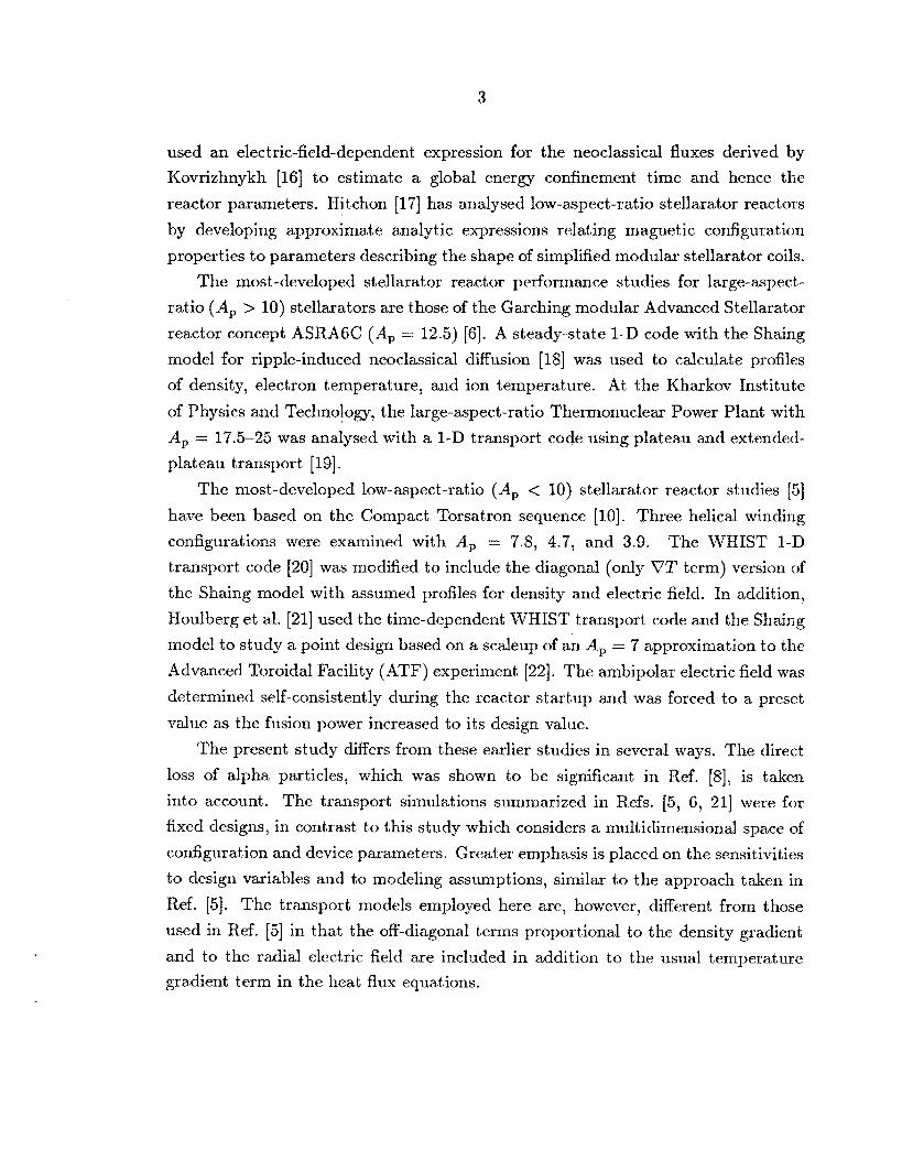
are in opposite directions for electrons and ions. The effect of the radial electric field
on the neoclassical component of the heat flux can be seen in Fig. 3, where parabolic
profiles of temperature, density, and electric potential are chosen and effective
thermal diffusivities, defined as xEff = -q,”“/(n,VT,) and evaluated at p = 0.75,
are plotted as functions of the normalized electric potential. The dcvice parameters
are those of the reference case; in Fig. 3a, (2’) = 8 keV and (n) = 3 x lo2’ mP3,
while in Fig. 3b, (7’) = 25 keV and (n ) = 7.5 x lo1’ m-’. In Fig. 3a the ions are
in the collisionless detrapping regime (x oc v), where the diffusion coefficients are
sensitive to the radial electric field, while the morc collisional electrons are at the
high-v end of the x cx 1/v regime where the diffusion coefficients are small. Here
v is the collision frequency. In the higher-temperature case shown in Fig. 3b, the
ions are deep in the low-collisionality, x cx Y regime where the transport coefficients
are small, while the electrons have just entered this regime from the l / v regime;
the electron heat flux is the dominant transport loss. The ion heat diffusivity in
Figs. 3a and 3b peaks at small negative values of the radial electric field where
the E x B and V B drifts cancel. The electron heat diffusivity in Fig. 3b peaks
at a small positive value of 50 for thc same reason. The heat diffusivities are not
symmetric about this resonance because of the V@ term in the heat flux equation.
The off-diagonal V@ term reduces the heat flux of the species having the larger
transport coefficients at the expense of the other species, with the net effect being a
reduction in the total heat flux. This leads to two very different modes of opcration,
depending on the sign of the electric field. At low collisionality, positive radial
electric fields (60 > 0) develop to retard the outward electron heat flux, leading
to the high-temperature, low-density “electron-root” mode of operation. At high
collisionality, negative radial electric fields ( E o < 0) develop to decrease the ion heat
flux, leading to the lower-temperature, high-density “ion-root” mode of operation.
10
01 E Y
ORNL-DWG 90-3215 FED I - _ -
0 1.5 3.0 4.5 -4.5 -3.0 -1.5
NORMALIZED ELECTRIC POTENTIAL, 50 Fig. 3. Effective thermal diff usivity versus normalized electric potential for an
A, = 5 reactor (a) at moderate collisionality ( ( T ) = 8 keV, (TI) = 3 x 10’’ ~ n - ~ ) and (b) at low collisionality ( ( T ) = 25 keV, ( n ) = 7.5 x 10’’ m-3).

13
For the examples discussed here, a reasonable energy confinement time ( TE 2 1 s
for up N 2 m) requires xeff 5 1 rn2-sW1 or (0 5 -3.3 in Fig. 3a and (0 2 3.4 in
Fig. 3b; (0 = f 3 are chosen as the reference values in this paper. The neoclassical
values of (0 expected and the temperatures at which the ion and electron roots are
expected to occur are estimated in Appendix B. The reference value of for the
electron root ((0 = +3) is close to the range expected neoclassically, but the (0 = -3
value for the reference ion-root case is more negative than expected neoclassically.
More negative values of l o could result from a preferential loss of ions from the
plasma, e.g. the alpha particles that are born in the near-perpendicular loss region
or that scatter into it as they slow down on the background plasma. However,
the flux of lost alpha particles is much less than the electric-field-dependent ion
and electron fluxes. It is unlikely that the dpha-particle loss modifies the potential
significantly because even a small potential change is associated with a large change
in the particle flux (analogous to the change in xeff seen in Fig. 3). Non-ambipolar
anomalous losses are likely to have more of an effect.
4.2 Electron-root operation
A POPCON plot for the reference electron-root case with = +3 is shown
in Fig. 4. The contours are those of constant auxiliary heating power, where the
O-MW contour indicates ignition. The potential operating points for a reactor are
on the ignition contour, with the exact location being determined by the desired
fusion output. The power required to heat the plasma to ignition is minimized by
choosing a startup path that passes through a saddle point in the external power
surface. This “Cordey pass” [31] occurs at low densities with electron-root operation
because of the improved neoclassical confinement associated with low collisionality
and because thc power per particle is maximized. The saddle point is not visible
in Fig. 4. The saddle-point power Psp is too small (<20 MW) to be important in
reactor design optimization for electron-root operation.
Along the nearly vertical branch,
the ignition temperature is nearly independent of the electron density. This is
characteristic of operation on the electron root and can be understood with a simple
scaling argument. With electron-root operation, ignition occurs at low collisionality
where the plasma energy losses are dominated by v-regime transport losses
(cx n2T-’/2) . The constant of proportionality depends on the machine parameters,
the electric field, and the assumed density profile. At ignition, these losses are just
The ignition contour has two branches.

2.0
.4
c? E 0 1.6 0 7 v
A
v c
i tz 1.2
n
a 21: w
0 w
M UJ > W
8 0.8
e
2 9
0.4
0
12
ORNL-DWG 90-3213 FED
0 a 16 24 32 40
DENSITY-AVERAGED TEMPERATURE, (T) (keV)
Fig. 4. POPCON plot for electron-root operation ((0 = 3) for a stellarator reactor with 1x0 = 10 m, up = 2 m, BO = 7 T, and €ha = 0.2. The auxiliary heating power contours are equally spaced in 5-MW intervals from 0 to 50 MW and in 50-MW intervals above 50 MW.
balanced by alpha-particle heating, which is approximately proportional to n2T2,
yielding an ignition temperature that is independent of density. Along the nearly
horizontal branch of the ignition contour, alpha-particle heating is balanced by
synchrotron radiation losses (a n1/2Tz /2 , including reabsorption), resulting in an
ignition density proportional to (T) ' i3 .
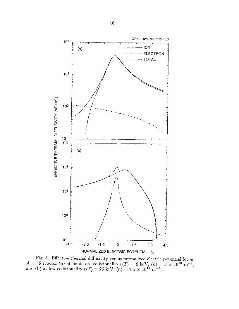
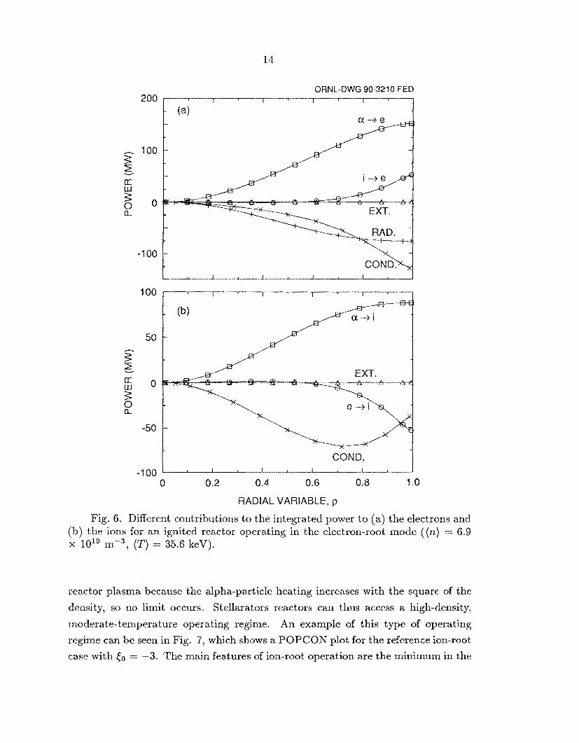
The temperature profiles for an ignited plasma (fusion power Pr = 3 GW,
(n ) = 6.9 x lo1' M - ~ , ( T ) = 35.6 keV) are shown in Fig. 5. The high edge ion
temperature is a result of the transport model and the assumed boundary condition;
a shorter edge-gradient length decreases this valiie. The integrated power to the
electrons within a radius p is shown in Pig. 6a and that for the ions in Fig. 6b. The
largest electron power loss (>60% at p = 1) is the net heat conduction, which is due
13
50
40
2
2 g 20
25 30 w cc 3
[I Lu
w I--
10
0
ORNL-DWG 90-321 7 FED I I I I 1
. , ,
\
, \ \
ELECTRONS '\, , , ,
\ \ ,
I \ \ I , ,
0 0.2 0.4 0.6 0.8 1 .o RADIAL VARIABLE, p
Fig. 5 . Profiles of electron and ion temperature for an ignited reactor operating in the electron-root mode (Pf = 3 GW).
to the diagonal (VT) term being slightly larger than the sum of the off-diagonal V@
term of the opposite sign and the Bn term. However, the radiation loss is larger
over most of the plasma ( p < 0.8). For the ions, the dominant term throughout
most of the plasma is conduction (due almost entirely to the off-diagonal terms),
except near the outside where the ion-to-electron heat transfer is comparable.
4.3 Ion-root operation
The only proposed operating limit [32] on the plasma density in a stellarator
increases with the square root of the input power, but it is not restrictive for a
14
200
h 100 3: 2 v
-1 00
100
50
ORNL-BWG 90-3210 FED r i i - - - - ~ / 1
--e$
\ . 1 E XT. w COND.
-1 00 0 0.2 0.4 0.6 0.8 1 .o
RADIAL VARIABLE, p
Fig. 6. Different contributions to the integrated power to (a) the electrons and (b) the ions for an ignited reactor operating in the electron-root mode ( ( n ) = 6.9 x 10'' m-', ( T ) = 35.6 keV).
reactor plasma because the alpha-particle heating increases with the square of the
density, so no limit occurs. Stellarators reactors can tlius access a high-density,
moderate-temperature operating regime. An example of this type of operating
regime can be seen in Fig. 9, which shows a POPCON plot for the reference ion-root
case with &, = -3. The main features of ion-root operation are the minirrium in the

15
ORNL-DWG 90-3214 FED 4.0
T E
3.2 0 F v
n c v
2.4 u) z W
L3 w
E w >
n
1.6
=? 2 i 3 0.8 0 >
0 0 4 a 12 16 20
DEN SIN-AVE RAG ED TEMPERATURE , (T) (keV)
Fig. 7. POPCON plot for ion-root operation ( t o = -3) for a stellarator reactor with Ro = 10 m, up = 2 m, Bo = 7 T, and &a = 0.2. The auxiliary powcr contours are shown at 20-MW intervals from 0 to 100 MW and at 100-MW intervals above 100 MW.
ignition density and the saddle point in the external power surface. The minimum
fusion power output along the ignition contour ( Pf,min) and the minimum volume-
averaged plasma beta ( (/?)min), which are important design constraints, occur near
the point of minimum ignition density ((n),). The auxiliary power required for
startup, which is also an important design constraint, can be approximated by the
steady-state saddle point power and is larger than with the electron-root mode of
operation. Simultaneous ramping of the plasma temperature and density is required
to follow the optimal startup path, similar to the startup scenario for a tokamak
react or.
Transport in different collisionality regimes dominates the power balance along
each of the two branches of the ignition contour in Fig. 7. Along the nearly vertical
16
branch, the electrons are at the high-v end of the I / v regime, where the transport
coefficients are small and the ions are just entering the v-regime from the 1/v
regime. The v-regime ion transport dominates, yielding a.n ignition contour similar
to that obtained at lower collisionality with the electron root. Bremsstrahlung and
impurity radia'tion are also important along the nearly vertical branch of the ion-
root ignition contour; they set a lower limit on the ignition temperature. Along
the high-temperature brmch of the ignition contour, the collisionality is lower, the
ions are deeper in the v-regime where their transport coefficients are reduced, a.nd
electrons are higher in the 1 / v regime, so that alpha-particle heating is balanced by
l/v-regime electron transport. Equating the l/v-transport losses (approximately
proportional to n 0 T 7 / 2 ) to the alpha-particle heating term yields an ignition density
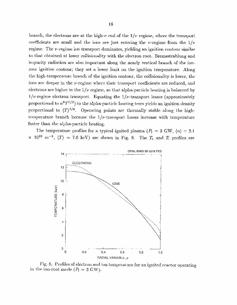
proportional to ('I")'/'. Operating points arc thermally stable along the high-
temperature branch because the l/v-transport losses increase with temperature
faster than the alpha-particle heating.
x lo2' n1-3, (7') = 7.6 kcV) are shown in Fig. 8.
The temperature profiles for a typical ignited plasma (Pf = 3 GW, ( n ) = 2.1
profiles are The T, and
ORNL-DWG 90-3216 FED I 1
' -1 I- , - -- 1
I' I I
0 0.2 0.4 0.6 0.8 1 .o RADIAL VARIABLE, p
Fig. 8. Profiles of electron arid ion temperature for an ignited reactor operating in the ion-root mode (Pf = 3 G W).

17
closer to each other than in Fig. 5 because of the shorter equilibration time. The
integrated power to the electrons within a radius p is shown in Fig. 9a; that for the
ions is shown in Fig. 9b. For the electrons, heat conduction, radiation, and ion-
electron heat transfer are all important; at p = 1, heat conduction and radiation
are comparable. The electron heat conduction is composed of comparable ripple-
induced diagonal and off-diagonal contributions and much smaller axisymmetric
ORNL-DWG 90-321 1 FED 300 i I I I I
g 100
3” z “ 0
0 a -100
I -200
-300 I I I I 1
50
25
a -25
0 $
-50
-75
-100 L I I I I
0 0.2 0.4 0.6 0.8 1 .o RADIAL VARIABLE, p
Fig. 9. Different contributions to the integrated power to (a) the electrons and (b) the ions for an ignited reactor operating in the ion-root mode ( ( n ) = 2.1 x lo2” m-’, ( T ) = 7.6 keV).

18
neoclassical and anoriialous contributions. For the ions, the dominant total loss is
conduction, The net heat conduction changes from negative (outward heat flow) to
positive at p N 0.54. This is because the negative diagonal (07’) term in the ion
heat flux is slightly larger than the positive sum of the V@ term of the opposite
sign and the V n term in the central part of the plasma, while it is smaller tham this
positive sum in the outer part of the plasma. The near-cancellation in the ion heat
conduction for the ion root is similar to the nea.r-cancellation in the electron heat
conduction for the electron root. It is due to the opposite sisn of the electric field
in the two cases.
4.4 Sensitivity to the magnitude ofthe electric field
Figures 10 and 11 show the sensitivity of stellarator reactor performance to the
magnitude of the radial electric field. These plots show ignition contours in (n)-(7’)
ORNL-BWG 90-3212 FED 2.0
h
c? E 0 N 0 v - 1.5 A
v c
g v> z: w Q 1.0 Q w c) a K W >
2 2 0.5
3 ?
0 0 18 20 30 40 50
DENSITY-AVERAGED TEMPERATURE, (T) (keV)
Fig. 10. POPCON plot showing the effect of the electric field on the ignition contour for an electron-root stellarator reactor.

19
ORNL-DWG 90-3209 FED 4
c5
r? E 0 cu 0
" 3 A
v t
i2 E 2 n
a
? W '
3 P
cn z
W c7 r I W
z
0
7
0 5 10 15 20 DENSITY-AVERAGED TEMPERATURE, (T) (keV)
Fig. 11. POPCON plot showing the effect of the electric field on the ignition contour for an ion-root stellarator reactor.
space for various values of to. Contours of constant ( p ) , which do not depend on
the density and temperature profiles, are also shown. Contours of constant Pf may
be different for each value of Eo due to differences in the temperature profiles and in
the values of r / T , . However, these effects are small for the range of considered,
and the Pf = 3 G W curve shown approximates the actual curves. A fusion power
of 3 G W corresponds to a net electrical output of -1.2 G W for typical values of the
thermal conversion efficiency and the energy multiplication in the reactor blanket.
With electron-root operation (Fig. lo ) , ignition occurs without exceeding the
desired total fusion power for values of (0 as low as +2.5, which is close to the range
expected neoclassically, as discussed in Appendix B. Larger values of f o shift the
reactor operating point (intersection of the Pf 3 GW curve and the ignition
contour) to lower temperature and slightly higher density (and lowcr (p) ) , where
the plasma may be less susceptible tm anomalous processes. The external power
=

20
required to reach ignition is small for electron-root operation, less than 20 MW for
the range of (0 shown. The resulting beta values are also low, ( p ) 5 6%. Larger absolute magnitudes of 50 are required for ignition with ion-root
operation (Fig. 11). For the case shown, values of &, 5 -3 are required in order
to achieve ignition without exceeding the desired Pi = 3 GW. The external power
required to reach ignition is sensitive to So, ranging from 10 MW when (0 = -4 and 50 MW when (0 = -3 to 230 MW when (0 = -2.5. The magnitudes
of (0 required are larger than those expected neoclassically, indicating that some
form of external control of the radial electric field would be necessary. This would
require a steady-state powcr input, similar to the recirculating power required for
current drive in a tokamak reactor. I€ the required values of (0 can be achieved, ion-
root operation offers some advantages. Contours of constant fusion power output
cross both branches of the ignition contour, so there is a choice for the operating
point: one at moderate values of ( n ) and ( T ) and one at higher (n) and lower
( T ) . Operating points on the high-temperature branch arc thermally stable; a
decrease in the plasma temperature away from the operating point will increase the
ignition margin and drive the plasma temperature back to the equilibrium value.
The negative electric field may also reduce transport caused by plasma turbulence
P31 *
5 . EFFECT OF ALPHA-PARTICLE LOSSES
The reference assumption about alpha-particle losses used in this paper is
that all trapped alpha particles are promptly lost from the plasma region. This
assumption is consistent with calculations of alpha-particle losses in Compact
Torsatron configurations with non-zero plasma pressure [25]. These alpha-particle
losses do not cause concerns for the reactor first wall, as they do in a tokamak
reactor, because the energetic alpha particles are channelled into the region external
to the torsatron coils, where their energy can be collected in large divertor
chambers. However, the alpha-particle heating of the background plasma is reduced,
which has prompted studies of modcrate-aspect-ratio [9] and low-aspect-ratio [25]
configurations with reduced alpha-particle losses. The potential irnprovemcnts in
plasma performance associated with reducing or eliminating the alpha-particle losses
are addressed in this section.
The effect of alpha-particle losses on the ignition contours for the reference
stellarator reactor operating in the electron- a d ion-root modes is shown in Fig. 12.

21
ORNL-DWG 90-3207 FED
0 1 2 3 4
VOLUME-AVERAGED DENSITY, (n) (1 020 m-3)
Fig. 12. Effect of alpha-particle losses on the ignition contour for the reference reactor operating in the electron-root or ion-root mode: dashed curves (without losses), solid curves (all trapped particles lost), and chain-dashed curves (only scattered losses).
The space is similiar to the POPCON space of Figs 10 and 11 except that ( T ) has
been replaced by the total fusion power Pf to better show the relationship between
the plasma variable that is most easily controlled ( ( n ) ) and the quantity that is
of most interest to reactor designers (Pf). The dashed curves are ignition contours
without alpha-particle losses, the solid curves are ignition contours when all trapped
alpha particles are lost, and the chain-dashed curves are ignition contours when
only the scattering component of the alpha-particle losses is considered. The third
situation can occur when otherwise closed orbits of energetic trapped particles are
disturbed by field errors or modulas coil ripple, leading to a stochastic drift of alpha
particles occupying a small region in velocity space.
22
With electron-root operation the main effect of reducing the alpha-particle losses
is to reduce the ignition temperature. Eliminating the direct component of the
alpha-particle losses decreases the ignition temperature from ~ 3 6 keV to ~ 3 0 keV.
Eliminating both the direct and scattering losscs reduces the ignition temperature
to 222 keV. But, as can be seen from Fig. 12, the higher temperatures do not have
a practical effect on reactor operation; (n) can be decreased to compensate for the
larger Pf and (p ) associated with higher temperatures. For all three cases ]?,,in < 1 GW, (/9)min < 5%, and Psp < 20 MW.
With ion-root operation, reducing the alpha-particle losses reduces (n ) * and
makes it easier to meet constraints on Pr, Psp, and (p ) . Eliminating the prompt
component of the alpha-particle losses decreases Pf,min from 2.5 GW to 0.9 GW,
(p)mii, from 3.0% to 2.0%) and Psp from 38 MW to 25 MW. With no alpha-particle
losses, Pf,min = 0.7 GW, (p),;, = 1.6%, and Psp = 24 MW.
6. SENSITIVITY T O DEVICE P,4RAMETERS
AND ASSUMPTIONS
6.1 Device parameter sensitivity
In order to determine the sensitivity of stellarator reactor performance to the
device parameters A,, €ha, ap, and 130, POPCON plots were generated for ranges
of these parameters, for both electron- and ion-root operation, with the loss of all
trapped alpha particles. Since constraints on Pf,min, (P),in, and Psp are important
for fusion reactor design, these quantities are obvious measures of performance.
However, Constraints on these quantities are easily satisfied with electron-root
operation because ignition can occur at low density. The ignition temperature
(2') * was chosen to characterize electron-root operation. For ion-root operation,
practical constraints on Pf,min were found to be more demanding than constraints
on the other two quantities; if Pf,,nin < 3 GW, then ( p ) < 8% and Psp < 100 MW for
the range of devicc parameters considered. The minimum fusion power at ignition
Pi ,m,n was used as a measure of performance for ion-root operation.
With electron-root operation the results can be surnrnarized with a simple
power law relation,
( 5 ) (T);t ~ 3071,-0.91A -0.46 0 . 2 3 ~ 0 ~ 0
p 'ha 0 p
with an rnis error of 3.7% for (T)Et < 50 keV. The ranges considered are A, = 3 10, €ha = 0.05-0.4, up = 1-3 m, Bo = 3- 10 T, and (0 = 2.5-5. All quantities in
the equations in Sections 6, 7, and 8 are in SI units, except for the temperatures
23
(in keV), densities (in lo2' m-'), and powers (in MW). For the reference set of
assumptions, decreasing the ignition temperature from the 37-keV value given by
Eq. (5) to the 22-keV value given in Section 5 for the case without alpha-particle
losses, thereby compensating for the alpha-particle losses, would require changing
t o to 4.8, A, to 15.5, or chi, to 0.021.
Equation (5) can be understood with the same scaling argument used to
explain the shape of the ignition curve in Fig. 4. With electron-root operation,
ignition occurs at low collisionality, where the transport losses are dominated by
v-regime transport, which is proportional to , 2 T - 1 / 2 [ ~ 2 A p 1 ~ ~ l a 2 B o a ~ . These losses
are balanced by alpha-particle heating, which is approximately proportional to
n2T2. Equating the alpha-particle heating to the transport losses yields an ignition
temperature
which is in good agreement with the trends observed in the calculations.
With ion-root operation, the results are more complicated because the dominant
= -3, which transport meclianism depends on the values of (n ) , ( T ) , and t o . For
is more negative than expected neoclassically,
(7) 1.33 2 .39 2.36 -1 .53 $'?;in = 3.13 x 10'Ap B, aP
with an rms error of 5.2%. The ranges considered are A, = 4-10, e l la = 0.05-0.3,
ap = 1.5-3 m, and BO = 5-10 T.
The
minimum density at ignition is at the intersection of the two branches of the ignition
contour. Along one branch the alpha-particle heating is balanced by l / v electron
transport (ix T7/2 (0"A,24~B02a ,4 ) , yielding an ignition density proportional to
T 3 / 4 5 ~ A , ' ~ 3 ' l " B ~ 1 a p 2 . ha Along the other branch, v-regime ion transport dominates,
yielding an ignition temperature proportional to I[,-, )-4/5A-2/5 P 'ha 1 /5B0a0 0 p' The
minimum density along the ignition contour is then
These results can also be explained with a simple scaling argument.
and P f , m i n , which is approximately proportional to ( ? I ) : (T)faEAp, is

24
which is similar to the trends observed in the calculations. Reproducing the
quantitative scalings with simple arguments is difficult because errors in the (n ) ,
and ( T ) , scalings are amplified when they are used to form the Pf,min scaling.
Reproducing the &, dependence with simple scaling arguments is even more
difficult because the dominant transport mechanisms can be different for different
values of to. When &, is reduced, the ions are closer to the resonance shown in Fig.
3a, and Pf,m;n scales differently with the device parameters. For example, when
(0 = -1, which is within the range expected neoclassically (see Appendix B),
0 .61 1 2 1 2.90 -1.98 F!tLin = 5.48 x 10⁸A; E),; B; a,
with an rms error of 3.5%" The ranges considered here axe A, = 5 10, €ha = (9.01
0.2, up = 1.5-3 m, and Bo = 5-10 T. For this value of t o , moderate A , and low
cha are required for reasonable values of Pf,min. For example, A, = 10, €ha = 0.05,
Bo = 7 T, and ap = 2 m results in Pf,min = 3.2 GW.
6.2 Sensitivity to profile assumptions
The density profile can affect reactor operation in several ways. Peaked profiles
produce more alpha-particle heating for the same average temperature and density
and result in more effective heating since the alpha-particle power is deposited
closer to the magnetic axis. Changing the density profile can also change the heat
transpcrt losses through the collisionality dependence of x or directly through the
V n ter Q in the heat transport equations. The resulting changes in the temperature
profile can either enhance or reduce these effects.
Table I summarizes the effect of the density profile shape on Pf,min, (P)min, and
Psp for the ion-root mode of reactor operation. 'rhe density profiles assumed are the
peaked, broad, and hollow profiles shown in Fig. 1 plus the corresponding profiles
with different edge densities. Other assumptions are those of the reference case.
Reactor performance is much better with the broad or hollow profile than with the
peaked density profile. The edge density has only a small effect; increasing it results
in slightly better performance with both the broad and hollow profiles.
The dramatically different results with the peaked density profile are due to
changes in the temperature profile caused by the V n component of the heat flux.
Peaking the deiisity profile causes the temperature profiles to become broader,
lowering the central temperature and raising the edge temperature. The higher
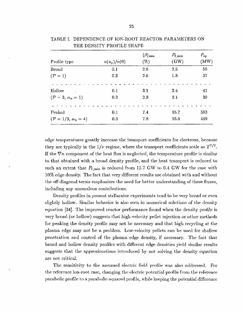
25
TABLE I. DEPENDENCE OF ION-ROOT REACTOR PARAMETERS ON
THE DENSITY PROFILE SHAPE
Broad
(P = 1)
0.1 2.8 2.5 50 0.3 2.6 1.8 37
edge temperatures greatly increase the transport coefficients for electrons, because
they are typically in the 1 /v regime, where the transport coefficients scale as T7i2. If the Vn component of the heat flux is neglected, the temperature profile is similar
to that obtained with a broad density profile, and the heat transport is reduced to
such an extent that Pf,min is reduced from 15.7 GW to 0.4 GW for the case with
10% edge density. The fact that very different results are obtained with and without
the off-diagonal terms emphasizes the need for better understanding of these fluxes,
including any anomalous contributions.
Density profiles in present stellarator experiments tend to be very broad or even
slightly hollow, Similar behavior is also seen in numerical solutions of the density
equation [34]. The improved reactor performance found when the density profile is
very broad (or hollow) suggests that high-velocity pellet injection or other methods
for peaking the density profile may not be necessary and that high recycling at the
plasma edge may not be a problem. Low-velocity pellets can be used for shallow
penetration and control of the plasma edge density, if necessary. The fact that
broad and hollow density profiles with different edge densities yield similar results
suggests that the approximations introduced by not solving the density equation
are not critical.
The sensitivity to the assumed electric field profle was also addressed. For
the reference ion-root case, changing the electric potential profile from the reference
parabolic profile to a parabolic-squared profile, while keeping the potential difference

26
between the plasma center and plasma edge constant, results in more peaked
temperature profiles, decreases Pf,,,in from 2.5 GW to 0.8 GW, and decreases the
startup power required from ~ 5 0 MW to ~ 2 5 MW. A square-root parabolic profile
increases Pf,min to 7.5 GW and increases the required startup power to 133 MW.
For the electron-root mode of operation, changing the electric potential profile from
parabolic to parabolic-squared decreases the ignition temperature from ~ 3 7 keV to
~ 2 5 keV; a square-root parabolic profile yields {T)* N 44 keV.
6.3 Sensitivity to anomdous transport
The reference value assumed for anomalous t hernial conductivity, ~ t ~ ' ~ ~ ~ - .._
5 x lo1* rn-'-s-'. Figure 13 shows the effect of anomalous transport on the ignition
contour for the reference reactor with all trapped alpha particles lost. The additional
anomalous transport has little effect on the ignition window for ion-root operation
ORNL-DWG 90-2524 FED 4
3 zi
5% 2 2 E
03 z W
m-
K O w v > - w - 4 z 3
>
e *- e 1
6
0 0 18 26 30 40 50
DENSITY-AVERAGED TEMPERATURE, (T) (keV) Fig. 13. EEcct of anomalous tra,nsport on the ignition contoiirs for stellarator
reactors.
27
because of the high densities involved. The value of Pf,min increases nearly linearly
from 2.5 GW to 5.5 GW as 6Znom increases from zero to 2 x lo2' m-'.s-'. If 3 GW
is taken as an upper limit on Pf,min, then the maximum tolerable value of 6Fom is 5 x 10'' m-'.s-'. For electron-root operation, additional anomalous transport only
affects the operating window at low density. The ignition temperature is relatively
un&ected at densities above ~ 1 . 5 x lo2' m-'. The value of Pf,m;n increases from
<1 GW to 8.4 GW, and Psp increases from <20 MW to 148 MW as 6r0" increases
from zero to 2 x IO2' rn-l-s-'. Values of of about lo2' m-lss-l can be
tolerated before Pf,min exceeds 3 GW.
7. RESULTS WITH AN EMPIRICAL TRANSPORT SCALING
Energy confinement times in present-day stellarat or experiments approximately
follow the Large Helical Device (LHD) empirical scaling [32],
0.58-0.69 0.84 2 0.75 TE = 0.17fe1,Px- ne Bo apRo
where fie is the line-averaged electron density and P, is the absorbed heating
power. Here TE is the total energy confinement time including radiation losses,
neoclassical diffusive losses, and any anomalous transport losses. An enhancement
factor fen is included to model possible confinement enhancement, such as the
factor of -2 improvement in r~ found in tokamaks in the transition from L-
mode behavior to H-mode behavior. The similarity in confinement and plasma
behavior in stellarators and tokamaks, coupled with the better external control
of the configuration properties in stellarators, suggests that such an improvement
may be possible. Other options for improved confinement in stellamtors include
operation in the second stability regime, larger radial electric fields, a n d reduced
plasma-wall interaction using divertors with remotely located target chambers. The
global LHD scaling is similar to gyro-reduced Bohm scaling [35], which is based on
a trapped-particle drift-wave turbulence model, except for the dependence on the
ion mass and plasma elongation. The LHD scaling is also similar to the global
confinement scaling obtained from ripple-induced neoclassical transport in the 1 / ~ regime except for the power dependence, which is stronger in the neoclassical
expression.

28
The LHD scaling i s rewritten here in terms of the plasma variable (2') instead
of Px,
TE LHD = 1.06 x 10- fen G .4 (12) 3 2.38 (n)0.26 ( T ) - 1 . 3 8 ~ 2 ~ 2 O P
Equation (12) is found from Eq. (11) by using the definition of the energy
confinement timc and by assuming that the density profiles in the experiments
from which the LWD scaling was inferred are roughly square-root parabolic, so that
fie '2 (4/3)(n).
The single-fluid global energy balance equation
w Pcond = 7
F
is solved for P, at fixed values of (n) and (7'). The total radiation power Prad
and alpha-particle heating power P, are found by numerically integrating over the
plasma volume using fixed temperature and density profile shapes.
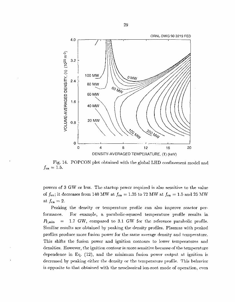
A PQPCQN plot for a stellarator reactor with A , = 5 , = 0.2, Bo = 7 T, and
ap = 2 m is shown in Fig. 14. Loss of trapped alpha particles is included, the density
profile is broad, and fen = 1.5. The temperature (2' = = T,) is characterized by
a profile parameter CUT: T = To(1 - p2),T. For this example, CUT = 1 is assumed.
Because the temperature dependence of the LHD confinement scaling is similar to
that obtained from neoclassical transport in the 1 /v regime, the ignition contour in
Fig. 14 is similar to that obtained with neoclassical ion-root operation, The strong
temperature dependence makes it necessary to operate at moderate temperatures
and high densities, and magnetic fields greater than 5 T are required. The auxiliary
power required for startup is 72 MW for this case.
Even modest improvements in the LHD confinement scaling result in signifi-
cantly better reactor performance. This same effect is seen in assessments of ignited
tokamaks [36] with the typical tokama,k scalings (power laws resembling the LHD
scaling). Figure 15 shows ignition contours for the same case as in Fig. 14 for four
values of fen. The contours with fen = 1.25, 1..5, 1.75, and 2 also correspond to
fen = 1 and Bo = 9.1 T, 11.3 T, 13.6 T, and 16 T, respectively. Also shown are
the contours for h; = 3 GW and ( p } = 5% and 10%. The minimum fusion output
for the case with fen = 1.25 is 6.3 GW. As fen increases, the ignition contour shifts
to lower values of ( T I } a.nd ( T ) ? allowing operation at smaller levels of fusion power.
Enhancement factors of 21.5 axe needed for ignited operation with tota.1 fusion
4.0
- c? E E 3.2 0 F v
n S v
i k 2.4 v) Z w a a w 2 1.6 a: w > e r” 9 2 0.8
0
29
ORNL-DWG 90-321 9 FED
100 M W 1 80 MW u 60 MW
40 M W \\ 20
0 4 8 12 16 20 DENSITY-AVERAGED TEMPERATURE, (T) (keV)
Fig. 14. POPCON plot obtained with the global LHD confinement model and fen = 1.5.
powers of 3 GW or less. The startup power required is also sensitive to the value
of fen; it decreases from 140 MW at fen = 1.25 to 72 MW at fen = 1.5 and 25 MW
at fen = 2. Peaking the density or temperature profile can also improve reactor per-
formance. For example, a parabolic-squared temperature profile results in
Pf,min 1.7 GW, compared to 3.1 GW for the reference parabolic profile.
Similiar results are obtained by peaking the density profiles. Plasmas with peaked
profiles produce more fusion power for the same average density and temperature.
This shifts the fusion power and ignition contours to lower temperatures and
densities. However, the ignition contour is more sensitive because of the temperature
dependence in Eci. (12), and the minimum fusion power output at ignition is
decreased by peaking either the density or the temperature profile. This behavior
is opposite to that obtained with the neoclassical ion-root mode of operation, even
=

30
QRNL-DWG 90-3220 FED
for the
though the diffusion coefficients depend on the plasma variables in a similar manner.
The different behavior is due to the off-diagonal terms that are present in the
neoclassical models, but not in the LHD scaling model.
8. OPERATION WITH Ib3E€e
Fusion reactors using B3Me fuel would have the advantage of a larger fraction of
the fusion power released in the kinetic energy of charged particles; the technological
difficulties associated with a high neutron flux environment would be reduced.
However, higher plasma temperatures and longer energy confinement times are
required because the cross-section for the D-3He reaction is much smaller than
that of the D-T reaction and peaks at higher temperatures. D3FIe reactors have
been evaluated for tokamaks [37,38] and for the less-developed tandem mirrors [39]

31
and field-reversed configurations [40,41], but not for stellarators. Part of the reason
for this neglect was the lower (p ) potential of earlier stellarator concepts; more
recent concepts have much higher beta limits [9,10]. The favorable temperature
dependence associated with the electron-root mode of operation suggests that
stellarators operating in this mode may be able to use D-3He fuel. A major
advantage is the absence of the need to drive the large plasma current (typically
25-50 MA) required for a D-3He tokamak reactor.
The existence of a loss region for energetic particles in stellarators makes
achievement of D-3He ignition more difficult than in tokamaks. However, the loss
of energetic particle energy due to scattering into the loss region is less severe than
with D-T operation because the 15.2-MeV proton produced by the D-3He reaction
is less affected by pitch-angle scattering than the 3.52-MeV alpha particle produced
by the D-T reaction. For example, ~ 5 % of the energy of the 15.2-MeV proton is lost
due to scattering into the loss region for a D-3He plasma temperature of 80 keV. The
corresponding fraction of the energy of the 3.52-MeV alpha particle lost at a D-T
plasma temperature of 15 keV is -35%. If ignition is reached, the loss region offers
some advantages. The accumulation of fusion-product ash, which is a problem for
D-3He tokamak reactors [38], is avoided. Since tritons produced from one branch
of the D-D side reaction do not accumulate in the plasma, the 14.1-MeV neutrons
produced by the D-T reaction are avoided, making a D-3He stellarator reactor more
nearly aneutronic than a D-3He tokamak reactor.
Ignition contours for a D-3He reactor with A, = 10, €ha = 0.05, BO = 8 T,
ap = 2 m, and a wall reflectivity R, = 95% are shown for three values of Eo
in Fig. 16. Profile assumptions are the same as for the reference D-'T case, and
the loss of energetic particles is included. The high-temperature branch of the
ignition contour is determined by the balance between synchrotron radiation and
fusion-product heating, while v-regime transport is the dominant loss along the
lower-temperature branch. The ignition contours for different values of to cross
each other because larger electric fields decrease the ignition temperature as in D-T
operation, but they also increase T'/%, resulting in increased synchrotron losses.
For the three cases shown in Fig. 16, Pf,,i, = 9.9 GW and (p),in = 33% for
EO = 3, = 3.3 GW and (p),;, = 17% for Eo = 4, and Pf,m;n = 2.6 GW and (p)min = 15% for t o = 5 . Parameter scans about these D-3He cases were
performed. The ranges considered are ( 0 = 3.5-5, A, = 3-10, 6ha = 0.01-0.1,

32
ORNL-DWG 90-3208 FED
Q 20 40 68 80 100
DENSITY-AVERAGED TEMPERATURE, (T) (keV)
Fig. 16. POPCON plot showing the effect of the electric field on the ignition contour for the base D3He reactor case.
up = 1-3 m, Bo = 7-12 T, and R, = 90% to 98%. The results can be summarized
with
(15j 0 . 6 2 -1.41 0 13 0.29 2.84 1.94 p[Lin = 203(1 - Rw) t o Ap. €ha BO up
(16) (p)gin(%) = 3473(1 - ~,)0.31~;0.81~-0.47 0 . 1 7 ~ - 0 . 6 1 -0.58
p 'ha 0 ap
with rnis errors of 6.8% in .Pf,min and 4.2% in (p)rrlil1.
These numerical results can also be explained with simple heuristic arguments.
For the range of temperatures considered, the D-He3 reaction rate coefficients are
approxiinately proportional to q2 and the ignition temperature (T), scales as it
does with D-T operation (Eq. Along the high-temperature branch of the ignition curve, synchrotron losses [cx n1/2T5/2 (1 - a,) 1 / 2 g 5 / 2 ap -1/21 are balanced
(6)).

33
by fusion-product heating, resulting in an ignition density proportional to T1I3( 1 - 1/3B5/3 . p f,min and (@),in occur near the point ( (n)*,(T)*) where the Rw) 0 UP
two branches intersect,
yielding 0.53133.33 2.33
p ‘ha 0
(p)m$el oc (1 - ~w)0.33~;1.07~;0.53 0 . 2 7 ~ - 0 . 3 3 -0.33 ‘ha 0
9. IMPLICATIONS FOR STELLARATOR REACTORS
One might expect that the reduction in fusion-product heating caused by the loss
of energetic trapped particles would make it difficult to reach ignition in stellarator
reactors. However, the calculations summarized here indicate that there are two
modes of D-T operation and one mode of D-3He operation that could lead to ignition
in stellarator reactors. Once ignition is reached, a velocity-space loss region for
energetic particles is only beneficial; it prevents the accumulation of thermalized
fusion products and helps channel the fusion-product power to external chambers
without affecting the first wall.
The most important conclusions concern the role of the radial electric field.
Both the electron and ion roots can exist in reactor-relevant stellarator plasmas,
but reactors optimized for ion-root operation would be very different from those
optimized for electron-root operation.
With electron-root operation, ignition occurs at relatively high temperatures
that are relatively independent of the electron density. The principal effect of
the alpha-particle losses is to increase the ignition temperature. Constraints on
the volume-averaged plasma beta and total fusion power output are relatively
unimportant because low-density operation can be used to compensate for the high
ignition temperatures. The values of the normalized electric potential required to
reach ignition (cO N 3) are near the range expected neoclassically, even with the
loss of all trapped alpha particles. The ignition temperature is relatively insensitive
to the machine and configuration parameters.
These findings suggest that stellarators operating in the electron-root mode
The relative insensitivity of this of operation may make attractive reactors.
34
mode to the machine and device parameters allows the reactor designer access
to economically favorable regions of the design space (sma.11 Ap and Bo). Orbit
optimization techniques that reduce the effective helical ripple amplitude do not
appear to be necessary, so that torsatron configurations having relatively simple
coil systenis, improved plasma access, a.nd natural divertor action could be used.
However, the relatively high temperatures and positive electric fields may lead
to excessive anomalous transport. Confirmation of the expected confinement
improvement from large positive electric fields at low eollisionality must await larger
experiments with more heating power [3].
If the expected confinement improvement from positive electric fields is not
realized, then the ion root offers an alternative mode of operation. However,
constraints on the total fusion output at ignition are more difficult to satisfy and
more sensitive to alpha-particle losses with ion-root operation. With configuration
paranieters similias to those of torsatrons, the values of (0 needed to meet constraints
on the total fusion power are more negative than those expected neoclassically,
suggesting that some form of external control of the electric field would be necessary,
which requires a steady-state power input, as in a tokamak reactor with current
drive. Modification of the radial electric field and a consequent improvement
of the ion thermal diffusivity by perpendicular neutml beam injection have been
demonstrated in a small stellarator [42]) but have not been demonstrated yet in a
large stellarator. If the recirculating power required to maintain the negative electric
potential is too large arid electric potexitids in the neoclassical range (&, N -1) a.re
obtained, then orbit optimization techniques will be necessary to reduce the effective
helical iipple amplitude. For example, it can he seen from Eq. (10) that the effective
helical ripple must be reduced to €ha = 0.03 for a typical. stelkarator reactor with
Bo = 7 T, up = 2 m, d4p = 5 , and Pf,min = 3 GW. This value of the effective helical
ripple amplitude is a factor of 7---10 sma.ller than that for Compact Torsatrons but
is siudiar to the values of €ha for Advanced Stelhators.
If the LHD anomalous confinement sealing persists into the reactor regime, then
a confinement enhancement factor of about 1.5 is necessary. This requirement is
reduced somewhat if magnetic fields in excess of 10 T are used or if pea,ked density
or temperature profiles can be obtained.
An orbit-optimized stellarator operating in the electron-root mode might make
an attractive D-3He reactor. By combining Eqs (15) and (16), it can be seen that an effective helical ripple amplitude of 0.1 and a magnetic field strength of 7.6 T are
35
required for a stellaxator reactor with Pf,min = 4 GW, (p ) = 20%, Eo -- 4, A, = 10, and up = 2 m. Effective helical ripples smaller than 0.1 have been achieved in quasi-
helical configurations [9], and values of (p) of 20% may be possible for a stellarator
with access to the second stability regime, but achieving the two simultaneously
may be very difficult.
The transport code results presented here indicate that the electron-root mode
of operation has the potential for an attractive stellarator reactor and may even
make a D-3He reactor feasible. Ion-root operation may also be possible, but
requires either control of the electric potential or a configuration with reduced
€he Obvious extensions of this work include using more sophisticated confinement
models (solving the electric field and density equations, better models for anomalous
transport). Constraints on the totad fusion power output and plasma beta also
need to be combined with engineering and reactor component constraints in order
to quantify the impact of the various transport assumptions on the total reactor
system [29].

37
Appendix A
THE COLTRANE TRANSPORT CODE
The transport survey code COLTRANE represents a compromise between a
global (0-D) approach [43] and a time-dependent 1;-D plasma simulation code
[20,44,45]. The spectral collocation method [46] is applied to the transport equations
in their int egral-differential form. The independent variables (electron and ion
temperatures) are expanded in an N-term series of Chebyshev polynomials. The
expansion coefficients are found by requiring that the integral-differential form of the
transport equations be satisfied on a discrete set of points known as the collocation
(ordering) points,
1 - c o s ( ~ j / N ) 2
, I < j < N - l . P i =
The collocation points are the interior extrema of the highest-order basis function
and are more closely spaced near the plasma boundary, where the solution can
change rapidly. This collocation yields equations representing power balances
over finite volumes as in the finite-element method. This discretely conservative
property causes the globally averaged quantities to converge rapidly as the number
of basis functions increases. Continuity conditions at each collocation point p j are
intrinsically satisfied, in contrast to the finite-element method, which requires that
the continuity conditions be explicitly imposed.
COLTRANE treats the general linear boundary condition Ta+b(clTa/dp)+c = 0
at the plasma boundary and qa = 0 at the plasma axis. Typically, the tempcrature
gradient scale length ap[(l/T,)(dTa/dp)]-l is specified to be 10 cm for both the
electrons and ions. The two equations coming from the boundary conditions, the
N - 1 finite-volume power balances, and an auxiliary condition on (7') are solved
iteratively for the extcrnal power and the N + 1 expansion coefficients for each
species. The Jacobian matrix used in the iterative method of solution is written in
a computationally efficient form which allows it to be evaluated numerically with
O ( N + 1) operations.
The most obvious way of constructing a POPCON plot with a steady-state
code is simply to construct a fine grid in (n)-(2') space and solve the fixed
temperature problem at each grid point. A more efficient approach solves the
fixed temperature problem on a coarse grid (typically 6 x 6) and calculates linear
sensitivity coefficients describing the change in the solution as (n) and (2') change.
The sensitivity cocfficients, found directly from the discretized equations with little

38
computational effort, are used to interpolate the solution between the coa,rse grid
points.
An ignited reactor case with A, = 5 , RQ - 2 m, Bo = 5 T, and €ha r= 0.2
was used to study the convergence properties of the collocation method. The density
and electric potential profiles are both parabolic squared with a central density of
3 x lo2’ rn-’ and (0 = -2. The residual power (error in the integrated power
balance) normalized to the total alpha-particle heating is sinall over most of the
plasnia region but peaks near the plasma boundary because of interpolation errors
in the temperature gradients between collocation points. However, the nature of the
collocation method prevents this interpolation error from propagating away from
the offending point. If the spike in the residual power near the plasma boundary
is excliided, the residual power decreases rapidly with increasing number of basis
functions. The maximum relative error in the integrated power balance for 0 5 p 5 0.9 converges approximately exponentially as the number of basis functions is
increased. Only 25 basis fiunctioiis are required before the residual error reaches the
level of numerical noise in this single-precision calculation. The average quantities
converge even more rapidly. An accuracy of 1% is obtained for the average electron
and ion temperatures at ignition with 10 basis functions, and 10% accuracy is
obtained with only 5 basis functions. The rapid convergence of the global quantities
is a direct consequence of solving the equations in integral form.
39
Appendix B ESTIMATE§ OF THE AMBIPOLAR ELECTRIC FIELD
The approach taken in this work is to assume values for the radial electric field
that are roughly consistent with solutions to the ambipolarity constraint and then
to investigate the sensitivity of the results to the assumed values. Rough estimates
for the neoclassical ambipolar electric field can be obtained by numerically solving
the ambipolarity constraint with fixed temperature and density profiles, as was done
in Ref. [47]. This type of analysis is repeated here in a manner that clarifies the
dependence of the electric field on the local plasma variables and the machine and
device parameters. Explicit criteria for the existence of the electron and ion roots
are also developed.
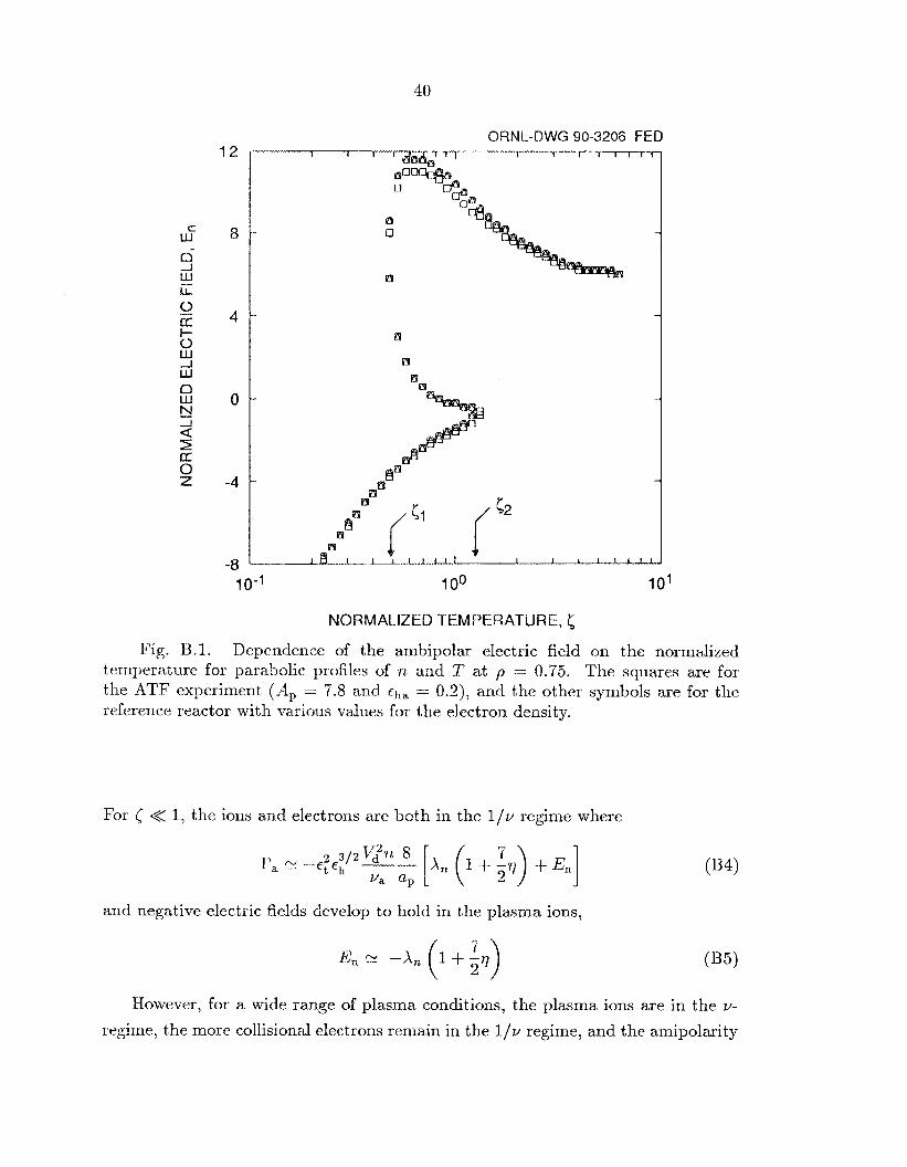
Figure B.l shows the normalized electric field E, = - ( e / k T ) ( d @ / d p ) as a
function of a dimensionless temperature
for four stellarators ranging from present-day experiments to low-aspect-ratio
reactors. Here T, = Ti = T , C, = v , T ~ J ’ ~ / ~ , C, = t;T3I2/n, u, = v,, + uei,
and v, = q i . In this plot, E, was found numerically from the ambipolarity
constraint using the integral expressions for the particle fluxes with parabolic profiles
of temperature and density.
For large values of the normalized temperature (5 >> l), ions and electrons are
both in the collisionless detrapping rcgime (v-regime), where the particle flux can
be approximated by
where Et = r / & , V d = -T/(apZ,eBp), A, = ( l / n ) ( d ~ z / d p ) , AT = (l /T)(dT/dp),
and = AT/X,. The radial electric field is assumed to be large enough that the
E x B poloidal drift dominates the bounce-averaged B x VB poloidal drift due to
the helical modulation of B ( t o >> €ha). Positive electric fields then develop to hold
in the more collisional and more lossy electrons,
12
8
4
0
-4
-8
40
ORNI_-DWG 90-3206 FED 1 I 1 I l l 1
i?3
a lli
10-1 100 101
NORMALIZED TEMPERATURE,
Fig. B.l. Dependence of the ambipolar electric field on the normalized temperature for parabolic profiles of n and 7' at p = 0.75. The squares are for the ATF experiment (A , = 7.8 and = 0.2), and the other symbols are for the reference reactor with various values for the electron density.
For 5 << 1, the ions and electrons are both in the 1/v regime where
and negative electric fields develop to hold in the plasma ions,
E, N -A, (1 + g7) (135)
However, for a wide range of plasma conditions, the plasma ions are in the v-
regime, the more collisional electrons remain in the 1 /v regime, and the ainipolarity

41
constraint has multiple roots. Equating the electron and ion fluxes yields a cubic
equation for the normalized electric field,
The minimum temperature Tl at which the electron root exists can be estimated
by determining when Eq. (B6) has precisely two real roots. This analysis yields
where 51 is the value of 5 corresponding to 2'1 and f ( q ) = 11 + 237 + 6.551~. This
value of 51 is indicated in Fig. B.l.
To find the maximum temperature T2 at which the ion root exists, a more
accurate expression for the ion flux must be used because the transition from the
ion root to the electron root occurs when the electric field is small, and the opposite
was assumed in deriving Eq. (B6). A good estimate for the maximum temperature
at which the ion root exists can be obtained by noting that the transition from the
ion root to the electron root occurs when the E x I3 and B x VI? drifts are equal,
or E, 3i - a c h / a p . Using this value for E, in Eq. (B6) yields the approximate value
of < at which the ion root disappears,
This value is also indicated in Fig. B.l.
and T2 = 29 lev for rL = 2 x 10'' m-' at p = 0.75.
Applying Eqs (B7) and (B8) to the reference reactor case yields 7'1 = 9.7 keV

42
ACKNOWLEDGMENTS
The first author (SLP) thanks Prof. P. N. Stevens of the University of 'Tennessee,
Knoxville for his guidance and for useful discussions on numerical methods. This
research was sponsored by the US. Department of Energy, Office of Fusion Energy,
under contract DE-AC05-840R21400 with Martin Marietta Energy Systems, Inc.

43
REFERENCES
[l] CARRERAS, B.A., GRIEGER, G., HARRIS, J.H., et d., Nucl. Fusion 28
[2] LYON, J.F., Fusion Technol. 17 (1990) 19; see also the papers 011 new
[3] See the papers on large next-generation stellarators in Fusion Technol.
(1988) 1613.
stellarator experiments in Fusion Technol. 17 (1990) 33-122.
17 (1990) 148-205.
[4] ITER Physics Group (presented by D. POST), ITER: Physics basis, in Plasma
Physics and Controlled Nuclear Fusion Research (Proc. 13th Int. Conf.
Washington, 1990), IAEA, Vienna (1991) IAEA-CN-53/F-1-3.
[5] LYON, J.F., CARRERAS, B.A., LYNCH, V.E., TOLLIVER, J.S.,
SVIATOSLAVSKY, I.N., Fusion Technol. 15 (1989) 1401.
[6] HARMEYER, E., KISSLINGER, J., RAU, F., WOBIG, H., in Fusion Reactor
Design and Technology (Proc. 4th IAEA Tech. Committee Mtg. Yalta, 1981;),
Vol. 2, IAEA, Vienna (1986) 37.
[7] MYNICK, H.E., HITCHON, W.N.G., Nucl. Fusion 23 (1983) 1053.
[8] PAINTER, S.L., LYON, J.F., Fusion Technol. 16 (1989) 157.
191 NUHRENBERG, J., ZILLE, R., Phys. Lett. 129A (1988) 113; see also
GRIEGER, G., BEIDLER, C., HARMEYER, E., et al., in Plasma Physics
and Controlled Nuclear Fusion Research (Proc. 12th Int. Cod. Nice, 1988),
Vol. 2, IAEA, Vienna (1989) 369.
[lo] CARRERAS, B.A., DOMINGUEZ, N., GARCIA, L., et al., Nucl. Fusion 28
(1988) 1195.
[ll] MILLER, R.L., Fusion Technol. 8 (1985) 1581.
[12] UO, K., IIYOSHI, A., OBIKI, T., et al., in Plasma Physics and Controlled
Nuclear Fusion Research (Proc. 9th Int. Cod . Baltimore, 1982), Val. 2,
IAEA, Vienna (1983) 209.
[13] KAZAWA, Y. , ITOU, Y., SUZUKI, S., OKAZAKI, T., MOTOJIMA, O., UO,
K., in Proc. Int. Stellarator/Heliotron Workshop (Kyoto, 1986), Vol. 11,
PPLK-6, Kyoto University, Kyoto (1987) 540.
8 (198.5) 1581; see also MILLER, R.L.,
BATHKE, C.G., KRAKOWSKI, R.A., et al., The Modular Stellarator
Reactor: A Fusion Power Plant, Los Alamos National Lab. Rep. LA-9737-MS
(1983).
[14] MILLER, R.L., Fusion Technol.

44
[15] VOTXOV, E.D., GEORGIEVSKI,J, A.V., KUZNETSOV, Yu.K., et al., in
Fusion Reactor Design and Technology (Proc. 4th IAEA Tech. Committee
Mtg. Ydta, 1986), Vol. 1, MEA, Vienna (1986) 393.
[16] MQVRIZHNYKH, L.M., Nucl. Fiision 24 (1984) 435.
[17] HITCHON, W.N.G., Nucl. Fusion 24 (1984) 91.
[18] SIIAING, K.C., Phys. Fluids 27 (1984) 1567.
[19] VOLKQV, E.D., RUDAKOV, V.A., SUPRUNENKO, V.A., Vopr. 4 t . Nauki
[20] BQULBERG, W.A., ATTENRERGER, S.E., I-IIVELY, L.M., Nucl. Fusion 22
[21] HOULBERG, W.A., EACATSKI, J.T., UCKAN, N.A., Fusion Technol. 10
[22] LYON, J.F., CARRERAS, BD.A., CHIPLEY, K.K., et al., Fusion Technol. 10
Tekh. Ser. Termoyadernyi Sintez 15 (1984) 36.
(1982) 935.
(1986) 227.
(1986) 179.
[23] CHANG, C.S., IIINTON, F.L., Phys. Fluids 25 (1982) 1493.
[24] MYNICK, H.E., Phys. Fluids 26 (1982) 1008.
[25] LYON, J.F., CARRERAS, B.A,, l>C)MINGUEZ, N., et al., Fusion Technol. 17
[26] RAU, F., WOX3fG) H., 2nd Workshop on Wendelstein VII-X, Max-Planck-
[27] TRUBNIKOV, B.A., in Reviews of Plasma Physics, Vol. 7 (LEONTOVICH,
[28] POST, D.E., et al., At. Data Nuel. Data Tables 20 (1977) 397.
[29] PAINTER, S.L., LYON, J.F., Optimization of torsatron reactors, submitted
[30] SHAING, K.C., HOKIN, S.A., Phys. Fluids 26 (1983) 2136.
[31] CORDEY, J.G., Nucl. Fusion 28 (1980) 1625.
[32] SUDO, S., TAKEIRI, Y., ZTJSHI, H., et al., Nucl. Fusion 30 (1990) 11.
[33] SHAING, K.C., CEUJME, E.C., HOULBERG, W.A. , Phys. Fluids B 2 (1990)
[34] BASTINGS, D.E., IIOUTJBERG, W.A., SHAING, K.C., Nucl.
(1990) 188.
Institut fur Plasmaphysik Rep. IPP-2/295 (1988).
M.A., Ed.), Consultants Bureau, New York (1979).
to Fusion Technol.
1492.
Fusion 25
(1985) 445. [35] GOJiDSTON, R.J., BIGLARI, II., HAMMETT, G.W., MEJADE, D.M.,
YOSHIKAWA, S., ZARNSTORFF, M.C., Bull. Am. Phys. SOC. 34 (1989)
1964.

45
[36] SANTARIUS, J.F., BLANCHARD, J.P., EMMERT, G.A., et al., in Fusion
13th Symp. Knoxville, 1989) Vol. 2, IEEE, New York Engineering (Proc.
(1990) 1039.
[37] UCKAN, N.A., Fusion Technol. 14 (1988) 299.
[38] EMMERT, G.A., KULCINSKI, G.L., BLANCHARD, J.P., et al., in Fusion
Knoxville, 1989) Vol. 2, IEEE, New York Engineering (Proc. 13th Symp.
(1990) 1043.
[39] SHUY, G.W., DABIRI, A.E., GUROL, H., Fusion Technol. 9 (1986) 459.
[40] BAKER, C.C., BOLON, A., CLEMMER, R., et al., in Proc. 8th Symp.
Engineering Problcrns of Fusion Research (San Francisco, 1979), Val. 2, IEEE,
New York (1980) 861.
[41] MILEY, G.H., et al., SAFFIRE D-3He Pilot Unit for Advanced-Fuel Develop-
ment, Report ER-645-1, Electric Power Research Institute (1979).
[42] MAASSBERG, H., W VII-A TEAM, NI TEAM, in Controlled Fusion and
Plasma Physics (Proc. 12th Eur. Cod. Budapest, 1985), Vol. 9F, Part 1,
European Physical Society (1985) 389.
[43] UCKAN, N.A., SHEFFIELD, J., in Fusion Engineering (Proc. 11th Symp.
Austin, 1985) Vol. 1, IEEE, New York (1986) $9.
[44] HOWE, H.C., Oak Ridge National Laboratory Report ORNL/TM-11521
[45] SINGER, C.E., POST, D.E., MIKKELSEN, D.R., et al., Comput. Phys.
[46] GOTTLIEB, D., ORSZAG, S.A., Numerical Analysis of Spectral Methods:
[47] MYNICK, H.E., HITCHON, W.N.G., Nucl. Fusion 23 (1983) 1053.
(1990).
Commun. 49 (1988) 275.
Theory and Applications, SOC. Ind. Appl. Math., Philadelphia (1977).


47
ORNL/TM- 1175G Dist. Category UC-426
L
INTERNAL DISTRIBUTION
1. Director, Fusion Energy Division 2. C. C. Baker 3. M. J. Saltmarsh 4. L. A. Berry 5. B. A. Carreras 6. R. A. Dory 7. J. L. Dunlap 8. H. H. Haselton 9. M. S. Lube11
10. T. E. Shannon 11-12. Laboratory Records Department
13. Laboratory Records, ORNL-RC 14-15. Central Research Library
16. Document Reference Section 17. Fusion Energy Division Library
18-19. ET/FE Division Publications Oftice 20. ORNL Patent Office
21-25. J. F. Lyon 26. W. Fulkerson 27. J. H. Harris 28. J. T. Hogan 29. W. A. Houlberg 30. R. C. Isler 31. M. Murakami 32. P. N. Stevens 33. D. W. Swain 34. N. A. Uckan
EXTERNAL DISTRIBUTION
35. Office of the Assistant Manager for Energy Research and Development, U.S. Department of Energy, Oak Ridge Operations Office, P.O. Box E, Oak Ridgc, T N 37831
Madison, WI 53706-1687
University of California, Los Angeles, CA 90024
Research, ER-50 Germantown, U.S. Department of Energy, Washington, DC 20545
Gaithersburg, MD 20879
36. J. D. Callen, Department of Nuclear Enginecring, University of Wisconsin,
37. R. W. Conn, Department of Chemical, Nuclear, and Thermal Engineering,
38. N. A. Davies, Acting Director, Office of Fusion Energy, Office of Energy
39. S. 0. Dean, Fusion Power Associates, Inc., 2 Professional Drive, Suite 248,
48
40. €3. K. Forsen, Bechtel Group, Inc., Research Engineering, P. 0. Box 3965, San
41. R. W. Gould, Department of Applied Physics, California ‘Institute of
42. R. A. Gross, Plasma Research Laboratory, Columbia University, New York,
43. U. M. Meade, Princeton Plasma Physics Laboratory, P.O. Box 451,
44. M. Roberts, International P’rogmnis, Office of Fusion Energy, Office of Energy
Francisco, CA 94119
Technology, Pasadena, CA 91125
NY 10027
Princeton, N J 08543
Research, ER-52 Germamtown, U S . Department of Energy, Washington, DC 20545
Institute of Technology, Atlanta, G A 30332
Rensselaer I’olytcchnic institute, Troy, NY 22181
India
8046 Garching, Federal Republic of Germany
5170 Julich, Federal Republic of Germany
Federal Repiiblic of Germany
Polytechnique F6d6rale de Lai.isa.nne, 21 Avenue des Bailis, CH-1007 Lausanne, Switzerland
Coiitrdke, F-13108 Saint- Paul-lez-Durance Gedex, France
France
England
45. W. M. Stacey, School of Nuclear Engineering and Health Physics, Georgia
46. D. Steiner, Nuclear Engineering Department, NES Binild.ing, Tibbetts Avenue,
47. R. Varma, Physical Research Laboratory, Navrangpura, Ahmedabad 380009,
48. Bibliothek, Max-Planck Institut fur Pla.smaphysik, Boltzrnannstrasse 2, D-
49. Bibliothck, Institut fur Plasmaphysik, KFA Julich GmbI-I, Postfach 1913, L)-
50. Bibliothek, KfK Karlsruhe GInbH, Postfach 3640, D-7500 Kulsruhe 1,
51. Bibliotheque, Centre de Recherches en Physique des Plasmas, Ecole
52. J. Tachon, CEN/Cadarache, Departement de Recherches sur la Fusion
53. I3ihliot hhque, CEN/ Cadarache, F- 13 108 Saint-Paul-lez-D urance CEDEX,
54. Library, AEA Fusion, Ciilharn Laboratory, Abingdon, Oxon OX14 3DB,
55. TJibrary, JET Joint Undertaking, Abingdon, Oxon OX14 3EA, England 56. Library, FQM-Institiiut voor Plasmafysica, Rijnhuizen, Edisonhaan 14, 3439
57. Library, National Institute for Fusion Science, Chikusa-ku, Nagoya 464-01 ~
58. Library, International Centre for Theoreticad Physics, P.O. Box 586, 1-34100
59. Library, Centro Richerche Energia Frascati, C.P. 65, 1-00041 Frascati (noma),
60. Library, Plasma Physics Laboratory, Kyoto University, Gokaslio, Uji, Kyoto
61. Plasma Research Laboratory, Australian National University, P.O. Box 4,
M N Nieuwegein, The Netherlands
Japan
Trieste, Italy
Italy
611, Japan
Canberra, A.C.T. 2601, Australia
49
62. Library, Japan Atomic Energy Research Institute, Naka Fusion Research
63. G. A. Eliseev, I. V. Kurchatov Institute of Atomic Energy, P.O. Box 3402,
64. V. A. Glukhikh, Scientific-Research Institute of Electro-Physical Apparatus,
65. I. Shpigel, Institute of General Physics, U.S.S.R. Academy of Sciences, Ulitsa
66. D. D. Ryutov, Institute of Nuclear Physics, Siberian Branch of the Academy
67. 0. Pavlichenko, Kharkov Physical-Technical Institute, Academical St. 1,
68. Deputy Director, Southwestern Institute of Physics, P.O. Box 15, Leshan,
69. Director, The Institute of Plasma Physics, P.O. Box 26, Hefei, Anhui, China
70. R. A. Blanken, Experimental Plasma Research Branch, Division of Applied
Establishment, 801-1 Mukoyama, Naka-machi, Naka-gun, Ibaraki-ken, Japan
123182 Moscow, U.S.S.R.
188631 Leningrad, U. S .S. R.
Vavilova 38, Moscow, U.S.S.R.
of Sciences of the U.S.S.R., Sovetskaya St. 5, 630090 Novosibirsk, U.S.S.R.
310108 Kharkov, U.S.S.R.
Sichuan, China (PRC)
P R C )
Plasma Physics, Office of Fusion Energy, Office of Energy Research, ER-542, Germantown, U.S. Department of Energy, Washington, DC 20545
71. R. A. E. Bolton, IREQ Hydro-Quebec Research Institute, 1800 Montee Ste.- Julie, Varennes, P.Q. JOL 2P0, Canada
72. D. H. Crandall, Director, Division of Applied Plasma Physics, Office of Fusion Energy, Office of Energy Research, ER-542, Germantown, U.S. Dcpartment of Energy, Washington, DC 20545
73. R. L. Freeman, General Atomics, P.O. Box 85608, San Diego, CA 92138-5608 74. I<. W. Gentle, RLM 11.222, Institute for Fusion Studies, University of Texas,
Austin, TX 78712 75. R. J. Goldston, Princcton Plasma Physics Laboratory, P.O. Box 451,
Princeton, N J 08543 76. J. C. Hosea, Princeton Plasma Physics Laboratory, P.O. Box 451, Princeton,
N J 08543 77. D. Markevich, Division of Confinement Systems, Office of Energy Research,
ER-55, Germantown, U.S. Department of Energy, Washington, DC 20545 78. R. H. McKnight, Experimental Plasma Physics Research Branch, Division of
Applied Plasma Physics, Office of Energy Research, ER-542, Germantown, U.S. Department of Energy, Washington, DC 20545
55, Germantown, U.S. Department of Energy, Washington, DC 20545
Technology, Cambridge, MA 02139
Applied Plasma Physics, Office of Energy Research, ER-541, Germantown, U.S. Department of Energy, Washington, DC 20545
82. J. W. Willis, Division of Confinement Systems, Office of Energy Research, ER-55, Germantown, U.S. Departrncnt of Energy, Washington, DC 20545
79. E. Oktay, Division of Confinement Systems, Office of Energy Research, ER-
80. R. R. Parker, Plasma Fusion Center, NW 16-288, Massachusetts Institute of
81. W. L. Sadowski, Fusion Theory and Computer Services Branch, Division of
50
83. A. Perez Navarro, Division de Fusion, CIEMAT, Avenida Complutense
84. Laboratory for Plasma and Fusion Studies, DepaxtIrimt of Nuclear 22, E-28040 Madrid, Spain
Engineering, Seoul National University, Shinrim-dong, Gwanak-ku, Seoul 151, Korea
Box 451, Princeton, N J 08543
Sciences, Ulitsa Vavilova 38, 117924 Moscow, U.S.S.R.
Kyoto, Japan
464-01, Japan
3402, 123182 Moscow, U.S.S.R.
Madison, VE'I 53706
Federal Republic of Cierrnany
85. J. E. Johnson, Plasma Physics Laboratory, Princeton University, P.O.
86. L. M. Kovrizhnykh, Institute of General Physics, U.S.S.R. Academy of
87. T. Obiki, Plasma Physics Laboratory, Kyoto University, Gokasho, Uji,
88. A. Iiyoshi, National Institute for Fusion Studies, Chikusa-ku, Nagoya
89. V. D. Shafranov, I. V. Kurehatov Institute of Atomic Energy, P.O. Box
90. J . 1;. Shohet, Torsatron/Stellarator Laboratory, University of Wisconsin,
91. G. Grieger, Max-Planck Institut fiir Plasmaphysik, D-8046 Garching,
92. K. Matsuoka, National. Institute for Fusion Science, Chikiisa-ku, Nagoya
93. D. G. Swanson, Physics Department, Auburn University, Auburn, AE
94. R. L. Linford, Los Alaiiios iiationd T,aboratory, MS F646, P.O. Box
95. K. 1. Thornassen, L-637, T,awrence Livermore National Laboratory, P.O.
96. R. F. Gandy, Physics Dcpartment, Auburn University, Auburn, AL
97. W. Wobig, Max-Planck Institut f& Plasmaphysik, D-8046 Garching,
98. D. T. Anderson, University ~f Wisconsin, Madison, WI 53706 99. K. Kondo, Plasma Physics Laboratory, Kyoto University, Gokasho, Uji,
464-01, Japan
36849-35 11
1663, Los Alamos, NM 87545
Box 5511, Livermore, CA 91550
36849-3511
Federal Republic of Germany
Japan
Japan
(Category Distribution UC-426, Experimental Plasma Physics) (53 copies)
100. F. Sano, Plasma Physics TAaboratory, Kyoto University, Gokasho, Uji,
101-153. Given distribution as shown in OSTI-4500, Magnetic Fusion Energy