s. k. syed-yusof, tharek abd. rahman spectrum emission mask for
TRANSCRIPT

Spectrum Emission Mask for Coexistence between Future WiMAX and Existing Fixed Wireless Access Systems
ZAID A. SHAMSAN, LWAY FAISAL, S. K. SYED-YUSOF, THAREK ABD. RAHMAN
Wireless Communication Center, Faculty of Electrical Engineering Universiti Teknologi Malaysia
81310 UTM, Skudai, Johor Bahru MALAYSIA
[email protected] http://fke.utm.my/wcc/
Abstract: - This paper introduces a new coexistence study of the future WiMAX system and existing fixed wireless access (FWA) systems and investigates its feasibility. Spectrum emission mask as an interference mitigation technique is used as well as interference to noise ratio (I/N) of -6 dB as one of standard sharing criterion value at FWA systems recommended by international telecommunication union radio sector ITU-R. Three channel bandwidths of (3.5, 7, and 10 MHz) of WiMAX system in the band 3500 MHz are selected to be studied with 7 MHz FWA channel in dense urban area. All parameters of the two systems are presented and methodology is explained. It is well known that frequency distance rules are an important of frequency coordination process in most radio services, so frequency and distance separations are determined and analyzed for both terms co-channel interference and adjacent channel interference in the different interference scenarios which are supposed. This coexistence and spectrum sharing study is considered as an initial step toward beyond 3G or IMT-Advanced coexistence with FWA systems. Key-Words: - Coexistence, Sharing, WiMAX systems, Fixed wireless access systems, Interference-to-noise ratio, Spectrum emission mask. 1 Introduction The radio spectrum is a limited and valuable resource, and as a result of the drastic growth demand for wireless communication applications, radio spectrum regulation and management have become increasingly significant [1]. Due to scarcity of the frequency spectrum, many bands are allocated for more than one radio service and therefore the sharing is necessity. The increased sharing of spectrum translates into a higher likelihood of users interfering with one another [2]. WiMAX (worldwide interoperability for microwave access) is based on IEEE 802.16 standard [3] recently considered as the 3rd generation broadband wireless access (BWA) system designed mainly for wireless metropolitan area networks (WMAN) [4]. WiMAX addresses the last-mile BWA problem in metropolitan areas and underserved rural areas for the advantages of fast and cost-effective deployment, it uses the band 3500 MHz which is currently allocated to Fixed Wireless Access (FWA) systems. Therefore, the impact of the interference of WiMAX as a new technology on FWA systems and vice versa needs to be studied. The interest for the use of 3500 MHz band (3400-3800) for FWA/BWA applications has increased
because its large size, high degree of reliability and wide coverage, particularly in geographical areas with severe rain. A different compatibility studies in the band 3500 MHz between broadband FWA and other services (point-to-point fixed links, electronic news gathering/outside broadcasting (ENG/OB) systems, fixed satellite systems (FSS) and radiolocation) were reported in [5], also impact from Ultra Wide Band (UWB) systems on BWA has been studied in [6]. Han-shin Jo et al. [7] studied the coexistence of orthogonal frequency division multiplexing (OFDM)-based systems beyond 3G (B3G) and point-to-point fixed services in the band 3500 MHz. In our study, spectrum emission mask is applied for both WiMAX and FWA systems to investigate the safe distance (geographical) separation and frequency (Spectral) separation between the two systems to ensure that both systems are able to coexist without mutual harmful interference in the dense urban geographical areas. The reminder of this paper is organized as follows. In section 2, concepts of coexistence and spectrum sharing are displayed while parameters of WiMAX (802.16) and FWA systems are presented in section 3 in detail. Section 4 is devoted to discuss sharing criterion. The method and procedure to do
WSEAS TRANSACTIONS on COMMUNICATIONS
Zaid A. Shamsan, Lway Faisal,S. K. Syed-Yusof, Tharek Abd. Rahman
ISSN: 1109-2742 627 Issue 6, Volume 7, June 2008
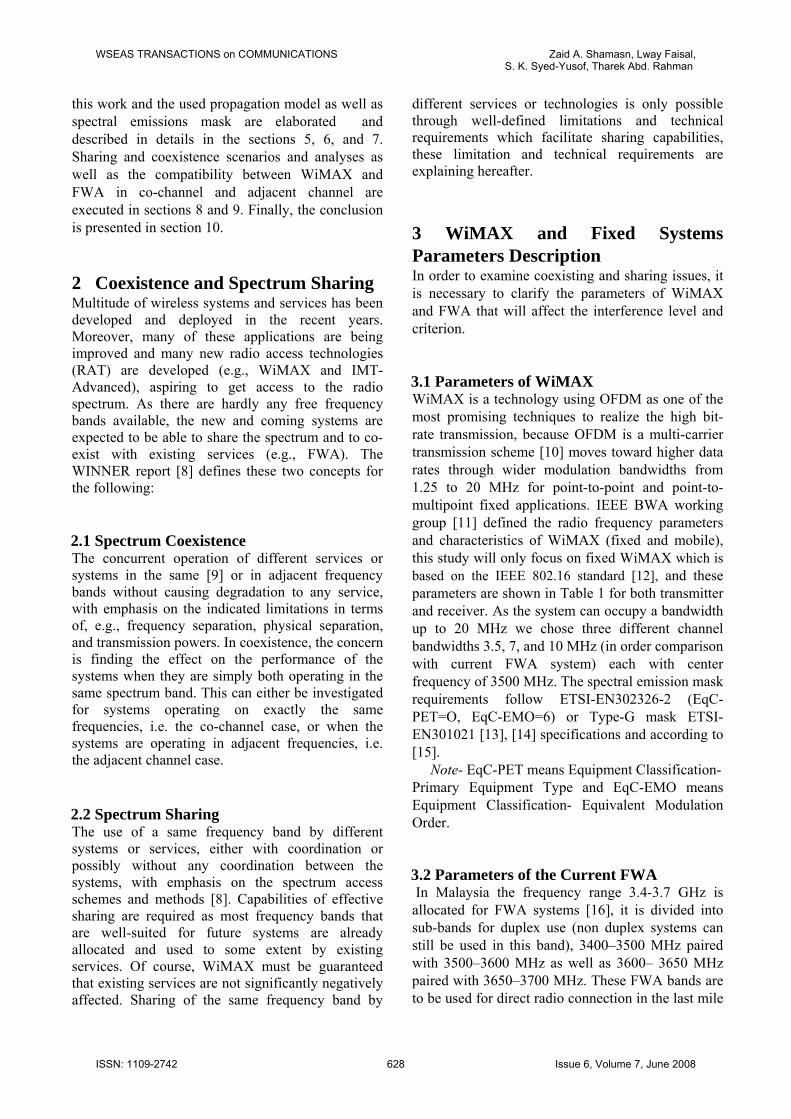
this work and the used propagation model as well as spectral emissions mask are elaborated and described in details in the sections 5, 6, and 7. Sharing and coexistence scenarios and analyses as well as the compatibility between WiMAX and FWA in co-channel and adjacent channel are executed in sections 8 and 9. Finally, the conclusion is presented in section 10. 2 Coexistence and Spectrum Sharing Multitude of wireless systems and services has been developed and deployed in the recent years. Moreover, many of these applications are being improved and many new radio access technologies (RAT) are developed (e.g., WiMAX and IMT-Advanced), aspiring to get access to the radio spectrum. As there are hardly any free frequency bands available, the new and coming systems are expected to be able to share the spectrum and to co-exist with existing services (e.g., FWA). The WINNER report [8] defines these two concepts for the following: 2.1 Spectrum Coexistence The concurrent operation of different services or systems in the same [9] or in adjacent frequency bands without causing degradation to any service, with emphasis on the indicated limitations in terms of, e.g., frequency separation, physical separation, and transmission powers. In coexistence, the concern is finding the effect on the performance of the systems when they are simply both operating in the same spectrum band. This can either be investigated for systems operating on exactly the same frequencies, i.e. the co-channel case, or when the systems are operating in adjacent frequencies, i.e. the adjacent channel case.
2.2 Spectrum Sharing The use of a same frequency band by different systems or services, either with coordination or possibly without any coordination between the systems, with emphasis on the spectrum access schemes and methods [8]. Capabilities of effective sharing are required as most frequency bands that are well-suited for future systems are already allocated and used to some extent by existing services. Of course, WiMAX must be guaranteed that existing services are not significantly negatively affected. Sharing of the same frequency band by
different services or technologies is only possible through well-defined limitations and technical requirements which facilitate sharing capabilities, these limitation and technical requirements are explaining hereafter. 3 WiMAX and Fixed Systems Parameters Description In order to examine coexisting and sharing issues, it is necessary to clarify the parameters of WiMAX and FWA that will affect the interference level and criterion. 3.1 Parameters of WiMAX WiMAX is a technology using OFDM as one of the most promising techniques to realize the high bit-rate transmission, because OFDM is a multi-carrier transmission scheme [10] moves toward higher data rates through wider modulation bandwidths from 1.25 to 20 MHz for point-to-point and point-to-multipoint fixed applications. IEEE BWA working group [11] defined the radio frequency parameters and characteristics of WiMAX (fixed and mobile), this study will only focus on fixed WiMAX which is based on the IEEE 802.16 standard [12], and these parameters are shown in Table 1 for both transmitter and receiver. As the system can occupy a bandwidth up to 20 MHz we chose three different channel bandwidths 3.5, 7, and 10 MHz (in order comparison with current FWA system) each with center frequency of 3500 MHz. The spectral emission mask requirements follow ETSI-EN302326-2 (EqC-PET=O, EqC-EMO=6) or Type-G mask ETSI-EN301021 [13], [14] specifications and according to [15]. Note- EqC-PET means Equipment Classification- Primary Equipment Type and EqC-EMO means Equipment Classification- Equivalent Modulation Order.
3.2 Parameters of the Current FWA In Malaysia the frequency range 3.4-3.7 GHz is allocated for FWA systems [16], it is divided into sub-bands for duplex use (non duplex systems can still be used in this band), 3400–3500 MHz paired with 3500–3600 MHz as well as 3600– 3650 MHz paired with 3650–3700 MHz. These FWA bands are to be used for direct radio connection in the last mile
WSEAS TRANSACTIONS on COMMUNICATIONS Zaid A. Shamasn, Lway Faisal,S. K. Syed-Yusof, Tharek Abd. Rahman
ISSN: 1109-2742 628 Issue 6, Volume 7, June 2008

between a fixed radio central station and subscriber terminal stations in a point-to-point and/or point-to-multipoint configuration. Countries have various frequency channel spacing within the 3.5 GHz bands 1.25, 1.75, 3.5, 7, 8.75, 10, 14, and 28 MHz can be used according to capacity needs. The spectral emission mask (is discussing in a next section) requirements follow ETSI-EN302326-2 (EqC-PET=O, EqC-EMO=4) [13] or Type-F mask ETSI-EN301021 [14] specifications according to [5]. We will focus on the parameters listed in Table 2.
Table 1: WIMAX system parameters
Table 2: FWA system parameters
Parameter Value
Center frequency of operation (MHz) 3500
Bandwidth (MHz) 7
Base station transmitted power (dBm)
35
Terminal station transmitted power (dBm)
22
Spectral emissions mask requirements
Type-F ETSI-
EN301021 Base station antenna gain (dBi) 17 Terminal station antenna gain (dBi) 20 Base station antenna height (m) 20 Terminal station antenna height (m) 1.5-10 Noise figure of base station (dB) 5 Noise figure of terminal station (dB) 7
4 Sharing Criterion For discussion of various sharing scenarios, it is necessary to develop appropriate rules for sharing. Intersystem interference can be described as short term or long-term, the short- term interference is rarely evaluated in the coordination literature as it is very much statistical in nature and not found for many services and will be specific to the cases considered [17], [18]. In this paper we consider long term interference only. The interference protection criteria can be defined as an absolute interference power level I, interference-to-noise power ratio I/N, or carrier-to-interfering signal power ratio C/I as shown in Fig. 1 [18]. ITU-R Recommendation F.758-2 details two generally accepted values for the interference–to–thermal-noise ratio (I/N) for long-term interference into fixed service receivers. When considering interference from other services, it identifies an I/N value of –6 dB or –10 dB matched to specific requirements of individual systems. This approach provides a method for defining a tolerable limit that is independent of most characteristics of the victim receiver, apart from noise figure.
Parameter
Each fixed service accepts a 1 dB degradation (i.e., the difference in decibels between carrier-to-noise ratio (C/N) and carrier to noise plus interference ratio C/(N + I) in receiver sensitivity. In some regard, an I/N of –6 dB becomes the fundamental criterion for coexistence [19], so it should be that [20]:
α≥− NI (1)
Where I is the interference level in dBm, N is the thermal noise floor of receiver in dBm and α is the protection ratio in dB and here has value of -6 dB which means that the interference must be approximately 6 dB below thermal noise as Fig. 1 shows. Fig.1: Interference protection criterions
Value
Center frequency of operation (MHz) 3500
Bandwidth (MHz) 3.5, 7, 10
Base station transmitted power (dBm)
36
Terminal station transmitted power (dBm)
24
Spectral emissions mask requirements
Type-G ETSI-
EN301021 Base station antenna gain (dBi) 16 Receiver antenna gain (dBi) 8 Base station antenna height (m) 30 Receiver antenna height (m) 2 Noise figure of Base station (dB) 4 Noise figure of receiver (dB) 7
C
N
I
C/I
C/N
I/
N
WSEAS TRANSACTIONS on COMMUNICATIONS Zaid A. Shamasn, Lway Faisal,S. K. Syed-Yusof, Tharek Abd. Rahman
ISSN: 1109-2742 629 Issue 6, Volume 7, June 2008
5 Method and Procedure The method consists in calculating the I/N ratio and then comparing it with the necessary I/N (-6 dB) at the victim receiver. Firstly Calculation of the interference level I (dBm) at the victim receiver by assessing the level of emissions from the interferer falling within the victim receiver bandwidth for both co-channel frequency and adjacent frequency situations according to [7]: ( ) ( ) AttbandcorrfMaskGrGtPtfI −+Δ+++=Δ _
(2) Where Pt: transmitted power of the interferer in dBm, Gt: gain of the interferer transmitter in dBi Gr gain of the victim receiver antenna in dBi Mask(∆f): attenuation of adjacent frequency due to mask where (∆f) is the difference between the carriers of interferer and the victim. corr_band: correction factor of band ratio, where corr_band= 0 dB if BWinterference < BWvictim or corr_band=-10log(BWinterference/BWvictim), if not. Att: attenuation due to the propagation (model in ITU-R P.452 is used). In the second phase Determine the thermal noise floor of victim receiver as the following: (3) ( victimBWNFN 10log10114 ++−= ) Where NF is noise figure of receiver in dB and BWvictim represent victim receiver bandwidth in MHz. Finally, substitute I and N of steps 2 and 3 above into (1) to determine the sharing and coexistence feasibility between the two systems and derive the relationship between: a). frequency separation ∆f and I/N ratio b). distance separation and I/N ratio. c). distance and frequency separation. 6 Propagation Model In particular, there is no single propagation model used for different sharing studies because the particular deployment of the systems requires using specific propagation model relevant to the specific system. WiMAX has a specific usage as it may be fixed or mobile and to operate in line or non-line of sight environment. The standard model agreed upon in CEPT and ITU for a terrestrial interference
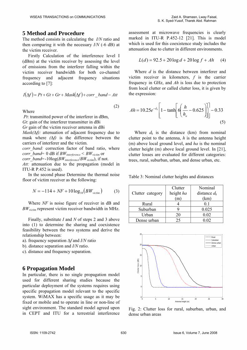
assessment at microwave frequencies is clearly marked in ITU-R P.452-12 [21]. This is model which is used for this coexistence study includes the attenuation due to clutter in different environments. AhfddL +++= log20log205.92)( (4) Where d is the distance between interferer and victim receiver in kilometers, f is the carrier frequency in GHz, and Ah is loss due to protection from local clutter or called clutter loss, it is given by the expression:
33.0625.06tanh125.10 −⎥⎥⎦
⎤
⎢⎢⎣
⎡
⎥⎥⎦
⎤
⎢⎢⎣
⎡⎟⎟⎠
⎞⎜⎜⎝
⎛−−= −
a
d
hheAh k
(5) Where dk is the distance (km) from nominal clutter point to the antenna, h is the antenna height (m) above local ground level, and ha is the nominal clutter height (m) above local ground level. In [21], clutter losses are evaluated for different categories: trees, rural, suburban, urban, and dense urban, etc. Table 3: Nominal clutter heights and distances
Clutter category Clutter
height ha (m)
Nominal distance dk
(km) Rural 4 0.1
Suburban 9 0.025 Urban 20 0.02
Dense urban 25 0.02
0 5 10 15 20 25 30-5
0
5
10
15
20
25
Antenna height (m)
Clu
tter l
oss
(dB
)
RuralSuburbanDense urbanUrban
Fig. 2: Clutter loss for rural, suburban, urban, and dense urban areas
WSEAS TRANSACTIONS on COMMUNICATIONS Zaid A. Shamasn, Lway Faisal,S. K. Syed-Yusof, Tharek Abd. Rahman
ISSN: 1109-2742 630 Issue 6, Volume 7, June 2008

The most geographical considered where WiMAX technology will be operated and deployments can be profitable [22] are dense urban and rural (the availability of other alternatives is limited) as well as low profitable in suburban and urban (medium population densities and high availability of other access network alternatives). Increasing of antenna height up to the clutter height leads to decrease the clutter loss, as shown in Table 3 and Fig. 2 which contain the four categories. In our case, dense urban category will be considered. 7 Spectrum Emission Masks The spectrum emission mask is a graphical representation of a set of rules that apply to the spectral emissions of radio transmitters. Such rules are set forward by regulatory bodies such as FCC and ETSI. It is defined as the spectral power density mask, within 250 % of the relevant channel separation (ChS), which is not exceeded under any combination of service types and any loading. The masks vary with the type of radio equipment, their frequency band of operation and the channel spacing for which they are to be authorized. WiMAX and FWA masks according to [13] and [14] are depicted and tabulated, where spectrum masks for WiMAX is declared in Table 4 for three channel bandwidths and 7 MHz channel spacing is only depicted in Fig. 3 in order to compare that with FWA mask for 7 MHz which is shown in Fig. 4 and Table 5.
±
Table 4: Reference frequencies for spectrum masks of Type-G ETSI-EN301021 (WiMAX)
Freq./Ch. Separation
(Normalized) (MHz)
0
0.5
0.5
0.71
1.06
2
2.5
Ch. Spacing (MHz)
0 dB
0 dB
-8 dB
-32 dB
-38 dB
-50 dB
-50 dB
3.5 0 1.75 1.75 2.49 3.71 7.0 8.75
7 0 3.5 3.5 4.97 7.42 14 17.5
10 0 5.0 5.0 7.1 10.6 20 25
-25 -20 -10 0 10 7.42 14-14 20 25 3.5-4.79-60
-50
-40
-30
-20
-10
0
10
-38
-32
-8
Frequency/Channel Separation (MHz)
Rel
ativ
e S
pect
ral P
ower
Den
sity
(dB
)
Fig. 3: WiMAX transmit spectrum mask for 7 MHz
The transmit spectrum mask is considered in this study because it may be used to generate a “worst case” power spectral density for worst case interference analysis purposes, where the coexistence study can be applied by spectrum emission mask as an essential parameter for adjacent frequency sharing analysis to evaluate the attenuation of interference signal power in the band of the victim receiver. To carry out this study the spectral emissions mask in the Fig. 3 is applied for coming interference from WiMAX systems and Fig. 4 is applied for coming interference from FWA systems as the following section details. Table 5: Reference frequencies for spectrum masks of Type-F ETSI- EN301021 (FWA)
Freq./Ch. Separation (Normalized)
0
(MHz)
0.5
0.5
0.71
1.06
2
2.5
Ch. Spacing (MHz)
0 dB
0 dB
-8 dB
-27 dB
-32 dB
-50 dB
-50 dB
7 0 3.5 3.5 4.97 7.42 14 17.5
WSEAS TRANSACTIONS on COMMUNICATIONS Zaid A. Shamasn, Lway Faisal,S. K. Syed-Yusof, Tharek Abd. Rahman
ISSN: 1109-2742 631 Issue 6, Volume 7, June 2008
-25 -20 -10 0 10 20 25-14 -7.42 144.97-3.5 7.42-60
-50
-40
-30
-20
-10
0
10
-8
-27
-32
Frequency/Channel Separation (MHz)
Rel
ativ
e S
pect
ral P
ower
Den
sity
(dB
)
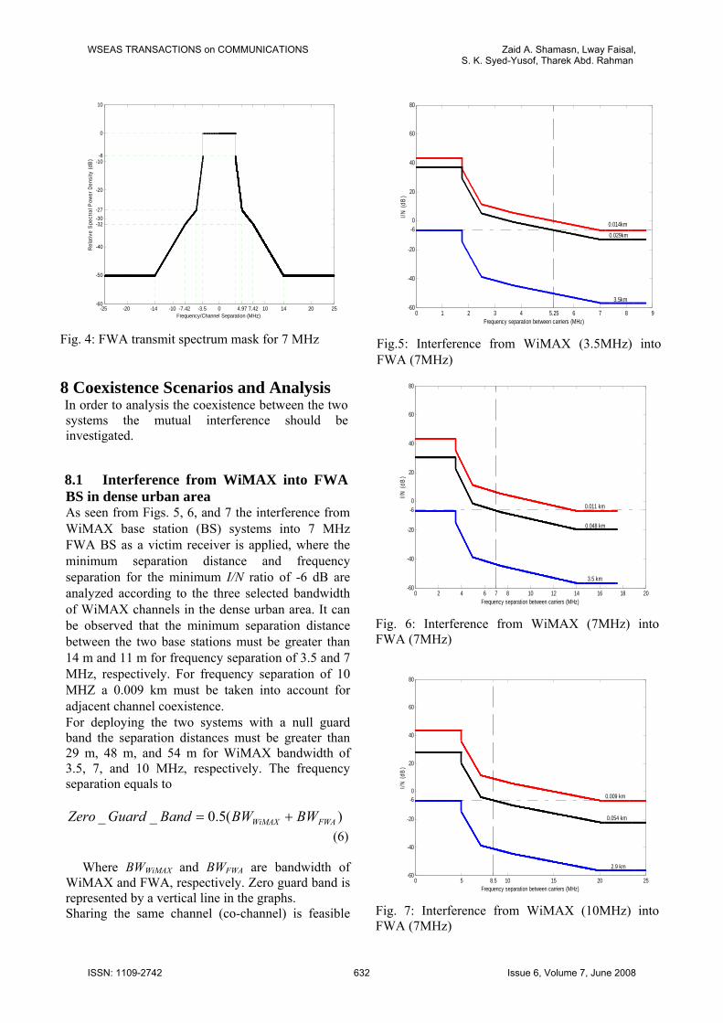
Fig. 4: FWA transmit spectrum mask for 7 MHz 8 Coexistence Scenarios and Analysis In order to analysis the coexistence between the two systems the mutual interference should be investigated. 8.1 Interference from WiMAX into FWA BS in dense urban area As seen from Figs. 5, 6, and 7 the interference from WiMAX base station (BS) systems into 7 MHz FWA BS as a victim receiver is applied, where the minimum separation distance and frequency separation for the minimum I/N ratio of -6 dB are analyzed according to the three selected bandwidth of WiMAX channels in the dense urban area. It can be observed that the minimum separation distance between the two base stations must be greater than 14 m and 11 m for frequency separation of 3.5 and 7 MHz, respectively. For frequency separation of 10 MHZ a 0.009 km must be taken into account for adjacent channel coexistence. For deploying the two systems with a null guard band the separation distances must be greater than 29 m, 48 m, and 54 m for WiMAX bandwidth of 3.5, 7, and 10 MHz, respectively. The frequency separation equals to
)(5.0__ FWAWiMAX BWBWBandGuardZero += (6) Where BWWiMAX and BWFWA are bandwidth of WiMAX and FWA, respectively. Zero guard band is represented by a vertical line in the graphs. Sharing the same channel (co-channel) is feasible
0 1 2 3 4 6 7 8 95.25-60
-40
-20
0
20
40
60
80
-6
Frequency separation between carriers (MHz)
I/N (d
B)
0.014km
0.029km
3.5km
Fig.5: Interference from WiMAX (3.5MHz) into FWA (7MHz)
0 2 4 6 8 10 12 14 16 18 207-60
-40
-20
0
20
40
60
80
-6
Frequency separation between carriers (MHz)
I/N (d
B)
0.011 km
0.048 km
3.5 km
Fig. 6: Interference from WiMAX (7MHz) into FWA (7MHz)
80
0 5 10 15 20 258.5-60
-40
-20
0
20
40
60
-6
Frequency separation between carriers (MHz)
I/N (d
B)
0.009 km
0.054 km
2.9 km
Fig. 7: Interference from WiMAX (10MHz) into FWA (7MHz)
WSEAS TRANSACTIONS on COMMUNICATIONS Zaid A. Shamasn, Lway Faisal,S. K. Syed-Yusof, Tharek Abd. Rahman
ISSN: 1109-2742 632 Issue 6, Volume 7, June 2008
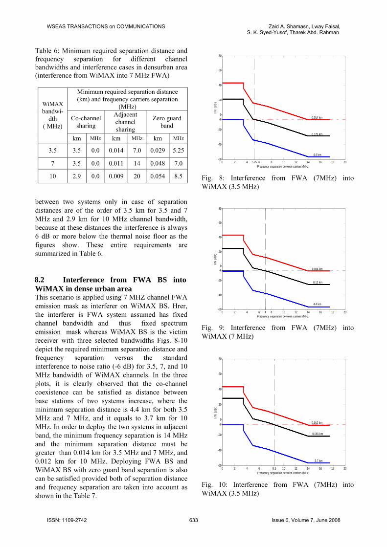
Table 6: Minimum required separation distance and frequency separation for different channel bandwidths and interference cases in densurban area (interference from WiMAX into 7 MHz FWA)
Minimum required separation distance (km) and frequency carriers separation
(MHz)
Co-channel sharing
Adjacent channel sharing
Zero guard band
WiMAX bandwi-
dth ( MHz)
km MHz km MHz km MHz
3.5 3.5 0.0 0.014 7.0 0.029 5.25
7 3.5 0.0 0.011 14 0.048 7.0
10 2.9 0.0 0.009 20 0.054 8.5
between two systems only in case of separation distances are of the order of 3.5 km for 3.5 and 7 MHz and 2.9 km for 10 MHz channel bandwidth, because at these distances the interference is always 6 dB or more below the thermal noise floor as the figures show. These entire requirements are summarized in Table 6. 8.2 Interference from FWA BS into WiMAX in dense urban area This scenario is applied using 7 MHZ channel FWA emission mask as interferer on WiMAX BS. Hrer, the interferer is FWA system assumed has fixed channel bandwidth and thus fixed spectrum emission mask whereas WiMAX BS is the victim receiver with three selected bandwidths Figs. 8-10 depict the required minimum separation distance and frequency separation versus the standard interference to noise ratio (-6 dB) for 3.5, 7, and 10 MHz bandwidth of WiMAX channels. In the three plots, it is clearly observed that the co-channel coexistence can be satisfied as distance between base stations of two systems increase, where the minimum separation distance is 4.4 km for both 3.5 MHz and 7 MHz, and it equals to 3.7 km for 10 MHz. In order to deploy the two systems in adjacent band, the minimum frequency separation is 14 MHz and the minimum separation distance must be greater than 0.014 km for 3.5 MHz and 7 MHz, and 0.012 km for 10 MHz. Deploying FWA BS and WiMAX BS with zero guard band separation is also can be satisfied provided both of separation distance and frequency separation are taken into account as shown in the Table 7.
0 2 4 6 8 10 12 14 16 18 205.25-60
-40
-20
0
20
40
60
80
-6
Frequency separation between carriers (MHz)
I/N (d
B)
0.014 km
0.175 km
4.4 km
Fig. 8: Interference from FWA (7MHz) into WiMAX (3.5 MHz)
0 2 4 6 8 10 12 14 16 18 2077-60
-40
-20
0
20
40
60
80
-6
Frequency separation between carriers (MHz)
I/N (d
B)
0.014 km
0.12 km
4.4 km
Fig. 9: Interference from FWA (7MHz) into WiMAX (7 MHz)
0 2 4 6 10 12 14 16 18 208.5-60
-40
-20
0
20
40
60
80
-6
Frequency separation between carriers (MHz)
I/N (d
B)
0.012 km
0.065 km
3.7 km
Fig. 10: Interference from FWA (7MHz) into WiMAX (3.5 MHz)
WSEAS TRANSACTIONS on COMMUNICATIONS Zaid A. Shamasn, Lway Faisal,S. K. Syed-Yusof, Tharek Abd. Rahman
ISSN: 1109-2742 633 Issue 6, Volume 7, June 2008

Table 7: Minimum required separation distance and frequency separation for different channel bandwidths and interference cases in dense urban area (interference from 7 MHZ FWA into WiMAX)
Minimum required separation distance (km) and frequency carriers separation
(MHz)
Co-channel sharing
Adjacent channel sharing
Zero guard band
WiMAX bandwi-
dth ( MHz)
km MHz km MHz km MHz
3.5 4.4 0.0 0.014 14 0.175 5.25
7 4.4 0.0 0.014 14 0.12 7.0
10 3.7 0.0 0.012 14 0.065 8.5
9 Compatibility between WiMAX and FWA According to previous results and by comparing Table 6 and Table 7, it is can be stated that WiMAX system and FWA system able to share and coexist in the co-channel frequency and adjacent channel by considering the separation distance and frequency separation as well as type of spectral emission mask and characteristics of two systems parameters. It should be noted that the results are more favourable for compatibility when using 10 MHz bandwidth channel for WiMAX which means higher data rates. The results also indicate that interference impacts form FWA on WiMAX is more worst than the interference from WiMAX base station into FWA base station , this is because of the wide mask requirements of FWA, higher antenna height of WiMAX base station, and higher antenna gain of FWA base station. Therefore, the minimum separation distance and frequency separation in Table 7 should be taken into account for deploying the two systems because it represents the worst case scenario between them. Interference-to noise ratio degrades as separation distance increases, and the same behavior occurs when frequency separation between carriers increases. Fig. 11 depicts the minimum distance against frequency offsets of 5MHz, 10MHz, and 15MHz for satisfying the minim-um I/N criteria to coexist the two systems when the FWA base station is the victim. Whereas, when WiMAX base station is the victim is depicted in Fig. 12.
2 4 6 8 10 12 14 16 18 20 225
6
7
8
9
10
11
12
13
14
15
16
Distance (m)
Freq
uenc
y of
fset
(MH
z)
3.5MHz and 7MHz WiMAX bandwidth10MHz WiMAX bandwidth
Fig. 11: Minimum distance vs. frequency offset to satisfy coexistence criteria (I/N=-6 dB) when the FWA base station is the victim
5 10 15 20 25 30 35 40 4525
6
7
8
9
10
11
12
13
14
15
16
Distance (m)
Freq
uenc
y of
fset
(MH
z)
3.5MHz and 7MHz WiMAX bandwidth10MHz WiMAX bandwidth
Fig. 12: Minimum distance vs. frequency offset to satisfy coexistence criteria (I/N=-6 dB) when the WiMAX base station is the victim 10 Conclusion In the above discussion the required frequency and distance separation between WiMAX and FWA systems have been derived. A coexistence analysis is thoroughly performed in this paper based on spectral emission mask and interference to noise ratio to determine mutual interference between BSs of both systems in the dense urban area. The coexistence problem is divided into two alternating terms, co-channel frequency sharing and adjacent channel coexistence, also a coexistence with zero guard band
WSEAS TRANSACTIONS on COMMUNICATIONS Zaid A. Shamasn, Lway Faisal,S. K. Syed-Yusof, Tharek Abd. Rahman
ISSN: 1109-2742 634 Issue 6, Volume 7, June 2008
between the two systems is introduced. The frequency separation required to protect both systems will be quite important when WiMAX and FWA are supposed to be close vicinity (distance around 0.014 km) for adjacent channel sharing and decreases significantly to deploy co-channel frequency sharing where the separation distance is larger than (4.4 km) for both 3.5 MHz and 7 MHz and (3.7 km) for 10 MHz WiMAX channel bandwidth. More studies are required in different categories areas and using other mitigation techniques. References: [1] B. Gabrys, R. Howlett, L. Jain (Eds), A Novel
Spectrum Sharing Scheme Using Relay Station With Intelligent Reception, KES 2006, Part III, LNAI 4253, , Springer-Verlag Berlin Heidelberg, 2006, pp. 465–472.
[2] J. Laster , J. Reed, Interference Rejection in Wireless Communications, IEEE Commun. Mag., Vol.14, 1997, pp. 37-62.
[3] A. Ghosh and D. Wolter, J. Andrews, C. Runhua, Broadband Wireless Access with WiMax/8O2.16: Current Performance Benchmarks and Future Potential, IEEE Comm. Mag., Vol.43, No.2, 2005, pp. 129–36.
[4] X. Fangmin, Z. Luyong, Z. Zheng, Interworking of Wimax and 3GPP Networks Based on IMS, IEEE Comm. Mag. Vol.45, No.3, 2007, pp.144-150.
[5] CEPT ECC Report 100, Compatibility Studies in the Band 3400-3800 MHz between Broadband Wireless Access (BWA) Systems and other Services, 2007.
[6] CEPT ECC Report 64, The Protection Requirements Of Radiocommunications Systems Below 10.6 GHz from Generic UWB Applications, 2005.
[7] J. Han-Shin, Y. Hyun-Goo, L. Jaewoo, C. Woo-Ghee, Y. Jong-Gwan, P. Han-Kyu, The Coexistence of OFDM-Based Systems Beyond 3G with Fixed Dervice Microwave Systems, Journal of Communications. and Networks, Vol. 8, No. 2, 2006, pp. 187-193.
[8] IST-2003-507581 WINNER, D6.1 v1.0, 2004. WINNER Spectrum Aspects: Methods for Efficient Sharing, Flexible Spectrum Use and Coexistence. 2004.
[9] D. Schilling, L. Milstein, R. Pickholtz, F. Bruno, E. Kanterakis, M. Kullback, V. Erceg, W. Biederman, D. Fishman, D. Salerno, Broadband CDMA for Personal
Communications Systems. IEEE Communications Magazine, Vol.29, 1991, pp. 86-93.
[10] L. Zhaogan, Z. Taiyi, S. Xiaodong, L. Xiaohe, Limitations of Current 4G Systems and Its Substitute Schemes with TDD/TDMA, WSEAS Transactions on Communications, Vol.6, No.11, 2007, pp. 850-860.
[11] R. Arefi, M. LaBrecque, IEEE 802.16-2004 and 802.16e RF Characteristics, Intel Corporation, IEEE C802.16-05/003, 2005. Available: http://www.ieee802.org/16/docs/05 /C80216-05003.pdf.
[12] A. Abderrahmane, M. Merouane, B. Messaoud, Diversity Techniques to Combat Fading in WiMAX, WSEAS TRANSACTIONS on COMMUNICATIONS, Vol.7, NO.2, 2008, pp. 43-51.
[13] ETSI EN 302 326-2 (V1.2.2), Fixed Radio Systems; Multipoint Equipment and Antennas; Part 2: Harmonized EN Covering the Essential Requirements of Article 3.2 of the R&TTE Directive for Digital Multipoint Radio Equipment, 2007.
[14] ETSI EN 301 021 (V1.6.1), Fixed Radio Systems; Point-to-Multipoint Equipment; Time Division Multiple Access (TDMA); Point-to-Multipoint Digital Radio Systems in Frequency Bands in the Range 3 GHz to 11 GHz, 2003.
[15] WiMAX 3.3-3.8 GHz mini-PCI Reference Design Series, Available: http://www.wavesat. com/ products/3GHz_MiniPCI_Series_Product _Brief jan 07.pdf.
[16] Zaid A. Shamsan, Lway Faisal, and Tharek Abd Rahman, ”Co-sited and Non Co-sited Coexistence Analysis between IMT-Advanced and FWA Systems in Adjacent Frequency band”, in Proceedings of the 7th WSEAS International Conference on Telecommunic- ations and Informatics (TELE-INFO '08), 2008, pp. 44-48.
[17] P. Gardenenier, M. Shafi, R. Vernall, M. Milner, Sharing Issues between FPLMTS and Fixed Services, IEEE Comm. Mag., Vol. 32, No. 6, 1994, pp. 74-78.
[18] NTIA Report 05-432, Interference Protection Criteria Phase 1 - Compilation from Existing Sources, 2005. Available: http://www.ntia.doc. gov/osmhome/reports/ntia05-432/ipc_phase_1_ report.pdf.
[19] IEEE STD 802.16.2-2004, IEEE Recommended Practice for Local and Metropolitan Area Networks Coexistence of Fixed Broadband Wireless Access Systems, 2004.
[20] ITU-R Recommendation F.1402, Frequency
WSEAS TRANSACTIONS on COMMUNICATIONS Zaid A. Shamasn, Lway Faisal,S. K. Syed-Yusof, Tharek Abd. Rahman
ISSN: 1109-2742 635 Issue 6, Volume 7, June 2008
Sharing Criteria between A Land Mobile Wireless Access System and a Fixed Wireless Access System Using the Same Equipment Type as The Mobile Wireless Access System, 1999.
[21] ITU-R Recommendation P.452-12, Prediction Procedure for the Evaluation of Microwave Interference between Stations on the Surface of
the Earth at Frequencies above About 0.7 GHz, 2005.
[22] T. Smura, Competitive Potential of WiMAX in the Broadband Access Market: a Techno-economic Analysis”, in Proceedings of ITS 2005, 2005. Available: http://www.netlab.tkk .fi/u/tsmura /publications/Smura_ITS05.pdf.
WSEAS TRANSACTIONS on COMMUNICATIONS Zaid A. Shamasn, Lway Faisal,S. K. Syed-Yusof, Tharek Abd. Rahman
ISSN: 1109-2742 636 Issue 6, Volume 7, June 2008