s. k. ghosh associates inc. - seaooseaoo.org/downloads/presentations_conf/2010_presentation_1... ·...
TRANSCRIPT

1
S. K. Ghosh Associates Inc.
www.skghoshassociates.com
FREQUENTLY MISUNDERSTOOD
IBC/ASCE 7 STRUCTURAL PROVISIONS
S. K. Ghosh and Susan Dowty
S. K. Ghosh Associates Inc.
Palatine, IL and Aliso Viejo, CA
www.skghoshassociates.com
All sections
referenced are from
ASCE 7-05,
unless otherwise
noted.
PROVISION#1
Enclosure ClassificationFor Wind Design
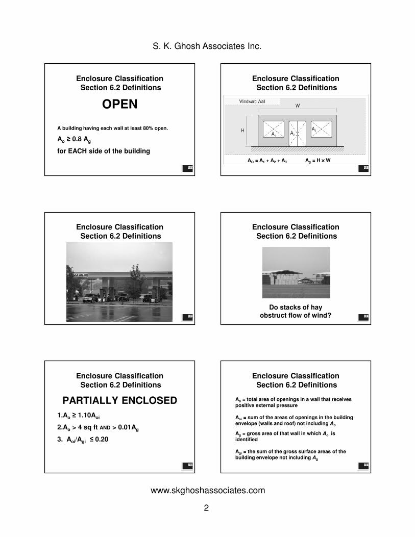
Enclosure Classification
Section 6.2 Definitions
Open
Partially Enclosed (can experience
“ballooning” or suction effects caused by the
build-up of internal pressure)
Enclosed
Internal Pressure
2
S. K. Ghosh Associates Inc.
www.skghoshassociates.com
Enclosure Classification
Section 6.2 Definitions
OPEN
A building having each wall at least 80% open.
Ao ≥ 0.8 Ag
for EACH side of the building
Enclosure Classification
Section 6.2 Definitions
AO = A1 + A2 + A3 Ag = H ×××× W
Enclosure Classification
Section 6.2 Definitions
Enclosure Classification
Section 6.2 Definitions
Do stacks of hay
obstruct flow of wind?
Enclosure Classification
Section 6.2 Definitions
PARTIALLY ENCLOSED
1.Ao ≥ 1.10Aoi
2.Ao > 4 sq ft AND > 0.01Ag
3. Aoi/Agi ≤ 0.20
Enclosure Classification
Section 6.2 Definitions
Ao = total area of openings in a wall that receives positive external pressure
Aoi = sum of the areas of openings in the building envelope (walls and roof) not including Ao
Ag = gross area of that wall in which Ao is identified
Agi = the sum of the gross surface areas of the building envelope not including Ag
3
S. K. Ghosh Associates Inc.
www.skghoshassociates.com
Enclosure Classification
Section 6.2 Definitions
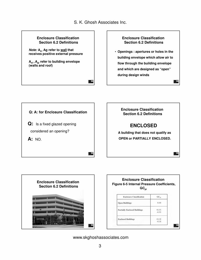
Note: Ao, Ag refer to wall that
receives positive external pressure
Aoi , Agi refer to building envelope
(walls and roof)
Enclosure Classification
Section 6.2 Definitions
• Openings : apertures or holes in the
building envelope which allow air to
flow through the building envelope
and which are designed as “open”
during design winds
Q: A: for Enclosure Classification
Q: Is a fixed glazed opening
considered an opening?
A: NO.
Enclosure Classification
Section 6.2 Definitions
ENCLOSED
A building that does not qualify as
OPEN or PARTIALLY ENCLOSED.
Enclosure Classification
Section 6.2 Definitions
Enclosure Classification
Figure 6-5 Internal Pressure Coefficients,
GCpi

4
S. K. Ghosh Associates Inc.
www.skghoshassociates.com
Basic Wind Equation
• For buildings with External and
Internal Pressure:
p = qGCp – qiGCpi
qi = Velocity pressure calculated for
internal pressure.
ASCE 7-98
Positive Internal Pressure
ASCE 7-98
Negative Internal Pressure Q: A: for Enclosure Classification
Q: Why does a building need to be
enclosed to use the Simplified Procedure?
A: See C6.4. GCpi = ±0.18 is assumed in the
tables. In a simple diaphragm building,
internal pressures cancel out for the walls
but not for the roof.
Q: A: for Enclosure Classification
Q: Should we treat roll-down doors and
operable louvers as openings?
A: Yes and No.
PROVISION#2
Seismic and Wind Design of Parapets
5
S. K. Ghosh Associates Inc.
www.skghoshassociates.com
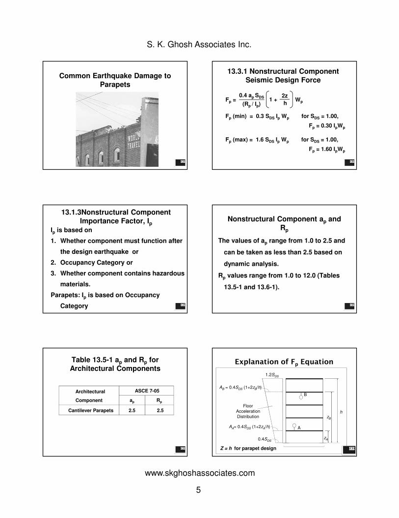
Common Earthquake Damage to
Parapets
13.3.1 Nonstructural Component
Seismic Design Force
Fp (min) = 0.3 SDS Ip Wp for SDS = 1.00,
Fp = 0.30 IpWp
Fp (max) = 1.6 SDS Ip Wp for SDS = 1.00,
Fp = 1.60 IpWp
Fp =0.4 ap SDS
(Rp / Ip)1 +
2z
hWp
13.1.3Nonstructural Component
Importance Factor, IpIp is based on
1. Whether component must function after
the design earthquake or
2. Occupancy Category or
3. Whether component contains hazardous
materials.
Parapets: Ip is based on Occupancy
Category
Nonstructural Component ap and
Rp
The values of ap range from 1.0 to 2.5 and
can be taken as less than 2.5 based on
dynamic analysis.
Rp values range from 1.0 to 12.0 (Tables
13.5-1 and 13.6-1).
Table 13.5-1 ap and Rp for
Architectural Components
Architectural
Component
ASCE 7-05
ap Rp
Cantilever Parapets 2.5 2.5
0.4SDS
1.2SDS
AA= 0.4SDS (1+2zA/h)
AB = 0.4SDS (1+2zB/h)
A
B
zA
zB
h
Floor
Acceleration
Distribution
Explanation of Fp Equation
Z = h for parapet design

6
S. K. Ghosh Associates Inc.
www.skghoshassociates.com
The 7-in. concrete parapet shown forms
part of a building assigned to SDC D with
a component importance factor of 1.0.
SDS= 1.0g at the site. Determine the
strength-level seismic design moment in
the parapet.
Example: Seismic Design of
Parapets
Example: Seismic Design of
Parapets
Weight of the parapet per linear foot is
Wp = 150 x 3 x 7/12 = 262.50 lb/ft
The seismic lateral force acting at the
centroid of the parapet is given by
ASCE Equation (13.3-1) as
Fp = (0.4apSDSIp / Rp)(1 + 2z/h )Wp
Where Ip = component importance
factor = 1.0
Example: Seismic Design of
Parapets
SDS = 1.0g
Wp = weight of parapet = 262.5 lb/ft
ap = component amplification factor from ASCE
Table 13.5-1 = 2.5
h = height of roof above the base = 20 ft
z = height of parapet at point of attachment =
20 ft
Example: Seismic Design of
Parapets
Rp = component response modification factor
from ASCE Table 13.5-1 = 2.5
Fp = (0.4 x 2.5 x 1.0 1.0 / 2.5) (1 + 2 x 20/20)Wp
= 1.2Wp = 315 lb/ft
Neither ASCE Equation (13.3-2) nor (13.3-3)
governs, and the bending moment at the
base of the parapet is
Mp = 1.5 Fp = 472.5 lb-ft/ft
Example: Seismic Design of
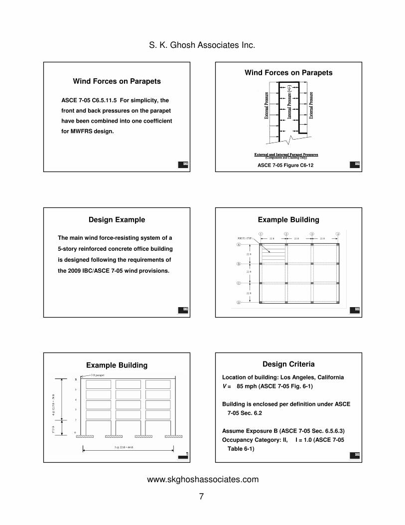
ParapetsWind Forces on Parapets
ASCE 7-05 Figure C6-12
7
S. K. Ghosh Associates Inc.
www.skghoshassociates.com
Wind Forces on Parapets
ASCE 7-05 C6.5.11.5 For simplicity, the
front and back pressures on the parapet
have been combined into one coefficient
for MWFRS design.
Wind Forces on Parapets
ASCE 7-05 Figure C6-12
Design Example
The main wind force-resisting system of a
5-story reinforced concrete office building
is designed following the requirements of
the 2009 IBC/ASCE 7-05 wind provisions.
Example Building
Example Building3 ft parapet
Design Criteria
Location of building: Los Angeles, California
V = 85 mph (ASCE 7-05 Fig. 6-1)
Building is enclosed per definition under ASCE
7-05 Sec. 6.2
Assume Exposure B (ASCE 7-05 Sec. 6.5.6.3)
Occupancy Category: II, I = 1.0 (ASCE 7-05
Table 6-1)
8
S. K. Ghosh Associates Inc.
www.skghoshassociates.com
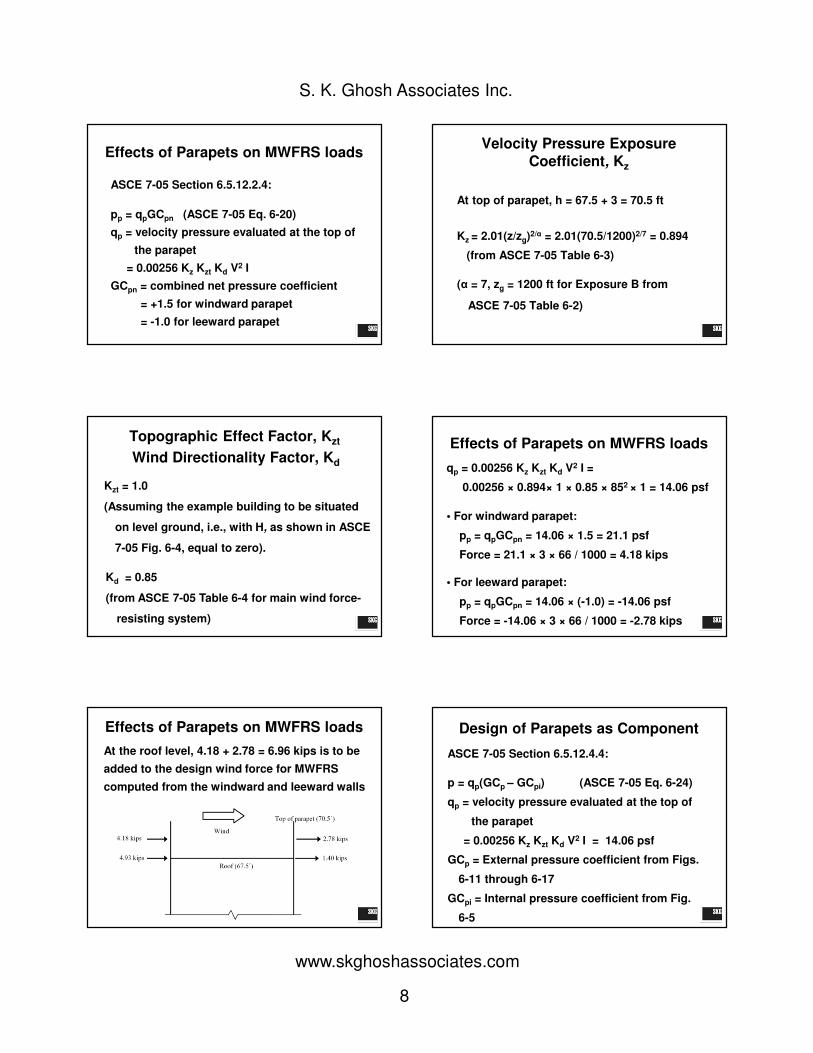
Effects of Parapets on MWFRS loads
ASCE 7-05 Section 6.5.12.2.4:
pp = qpGCpn (ASCE 7-05 Eq. 6-20)
qp = velocity pressure evaluated at the top of
the parapet
= 0.00256 Kz Kzt Kd V2 I
GCpn = combined net pressure coefficient
= +1.5 for windward parapet
= -1.0 for leeward parapet
At top of parapet, h = 67.5 + 3 = 70.5 ft
Kz = 2.01(z/zg)2/α = 2.01(70.5/1200)2/7 = 0.894
(from ASCE 7-05 Table 6-3)
(α = 7, zg = 1200 ft for Exposure B from
ASCE 7-05 Table 6-2)
Velocity Pressure Exposure
Coefficient, Kz
Topographic Effect Factor, Kzt
Wind Directionality Factor, Kd
Kzt = 1.0
(Assuming the example building to be situated
on level ground, i.e., with H, as shown in ASCE
7-05 Fig. 6-4, equal to zero).
Kd = 0.85
(from ASCE 7-05 Table 6-4 for main wind force-
resisting system)
Effects of Parapets on MWFRS loads
qp = 0.00256 Kz Kzt Kd V2 I =
0.00256 × 0.894× 1 × 0.85 × 852 × 1 = 14.06 psf
• For windward parapet:
pp = qpGCpn = 14.06 × 1.5 = 21.1 psf
Force = 21.1 × 3 × 66 / 1000 = 4.18 kips
• For leeward parapet:
pp = qpGCpn = 14.06 × (-1.0) = -14.06 psf
Force = -14.06 × 3 × 66 / 1000 = -2.78 kips
Effects of Parapets on MWFRS loads
At the roof level, 4.18 + 2.78 = 6.96 kips is to be
added to the design wind force for MWFRS
computed from the windward and leeward walls
Design of Parapets as Component
ASCE 7-05 Section 6.5.12.4.4:
p = qp(GCp – GCpi) (ASCE 7-05 Eq. 6-24)
qp = velocity pressure evaluated at the top of
the parapet
= 0.00256 Kz Kzt Kd V2 I = 14.06 psf
GCp = External pressure coefficient from Figs.
6-11 through 6-17
GCpi = Internal pressure coefficient from Fig.
6-5

9
S. K. Ghosh Associates Inc.
www.skghoshassociates.com
Effective wind area of the parapet:
Span = 3 ft
Width = 66 ft (> span/3)
A = 3x66 = 198 ft2
External Pressure Coefficient, GCp
Load Case A (ASCE 7-05 Section 6.5.12.4.4)
Positive wall GCp = 0.68 (Figure 6-17 Zones 4
and 5)
Applied to front surface of the parapet
External Pressure Coefficient, GCp
Load Case A (ASCE 7-05 Section 6.5.12.4.4)
Negative roof edge GCp = -1.76 (Figure 6-17
Zone 2*)
Applied to back surface of the parapet
*Corner Zone 3 is treated as Zone 2 because the parapet is 3 ft high
(Figure 6-17 Note 7)
External Pressure Coefficient, GCp
Load Case A (ASCE 7-05 Section 6.5.12.4.4)
GCp = 0.68 – (-1.76) = 2.44
GCpi = -0.18 for enclosed building (uniform
porosity)
However, internal pressures on both surfaces of
the parapet cancel each other out.
p = 14.06 x 2.44 = 34.31 psf
External Pressure Coefficient, GCp
Load Case B (ASCE 7-05 Section 6.5.12.4.4)
Effective wind area = 198 ft2
Positive wall GCp = 0.68 (Figure 6-17 Zones 4 and
5)
Applied to back surface of the parapet
External Pressure Coefficient, GCp
Load Case B (ASCE 7-05 Section 6.5.12.4.4)
Negative wall GCp = -0.76 (Figure 6-17 Zone 4)
= -1.23 (Figure 6-17 Zone 5)
Applied to front surface of the parapet
External Pressure Coefficient, GCp

10
S. K. Ghosh Associates Inc.
www.skghoshassociates.com
Load Case B (ASCE 7-05 Section 6.5.12.4.4)
GCp = 0.68 – (-0.76) = 1.44 (For Zone 4)
= 0.68 – (-1.23) = 1.91 (For Zone 5)
GCpi = -0.18 for enclosed building (uniform
porosity)
However, internal pressures on both surfaces of
the parapet cancel each other out.
p = 14.06 x 1.44 = 20.24 psf (Zone 4)
= 14.06 x 1.91 = 26.85 psf (Zone 5)
External Pressure Coefficient, GCp
Clearly, Load Case A governs
Thus, design uniform wind pressure on the
whole width of the parapet
p = 34.31 psf
Design of Parapets as Component
Q: A: for Wind Design of Parapet
Q: In Section 6.5.12.4.4 (parapets for
C&C), the definition for the factor GCpi is
based on the porosity of the parapet
envelope. How is the porosity of the
parapet determined?
Q: A: for Wind Design of Parapet
A: In the case of parapets, it is expected
most cases to have uniform porosity, so the
"enclosed" classification (+0.18, - 0.18)
would be appropriate. However, if the two
surfaces of the parapet are very different
(one has openings, the other is fully
sealed), the partially-enclosed case might
be relevant.
Q: A: for Wind Design of Parapet
Q: What is the wind load on the parapet using
Method 1, Simplified Procedure?
A: There is no clear answer. Some
jurisdictions do not allow Method 1 to be
used for buildings with parapets.
PROVISION#3
Torsion, Torsional Irregularity and Direction
of Seismic Loading

11
S. K. Ghosh Associates Inc.
www.skghoshassociates.com
QEδδδδxe
V
ASCE 7-05 12.8.4 Horizontal
Distribution of Forces
• Rigid diaphragms
– Seismic story shear is to be distributed to elements
of seismic-force-resisting system based on stiffness
of vertical-resisting elements
• Flexible diaphragms
– Seismic story shear is to be distributed to elements
of seismic-force-resisting system based on tributary
areas
• Torsion
– Torsional moment due to difference in location of center of
mass and center of resistance
must be considered for rigid diaphragms
• Accidental torsion
– For rigid diaphragms, must be included in addition to the
torsional moment
• Displacement of center of mass = 5% building
dimension perpendicular to direction of applied forces
ASCE 7-05 12.8.4 Horizontal
Distribution of Forces Failure – Torsion
1976 Philippines
12
S. K. Ghosh Associates Inc.
www.skghoshassociates.com
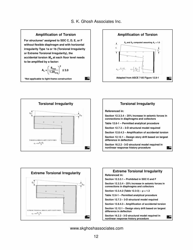
Amplification of Torsion
For structures* assigned to SDC C, D, E, or F
without flexible diaphragm and with horizontal
irregularity Type 1a or 1b (Torsional Irregularity
or Extreme Torsional Irregularity), the
accidental torsion Mta at each floor level needs
to be amplified by a factor:
Ax = δmax
1.2δavg
2
≤ 3.0
*Not applicable to light-frame construction
Amplification of Torsion
δA and δB computed assuming Ax = 1.0
Adapted from ASCE 7-05 Figure 12.8-1
Torsional Irregularity Torsional Irregularity
Referenced in:
Section 12.3.3.4 – 25% increase in seismic forces in
connections in diaphragms and collectors
Table 12.6-1 – Permitted analytical procedure
Section 12.7.3 – 3-D structural model required
Section 12.8.4.3 – Amplification of accidental torsion
Section 12.12.1 – Design story drift based on largest difference in deflection
Section 16.2.2 - 3-D structural model required in nonlinear response history procedure
Extreme Torsional Irregularity Extreme Torsional Irregularity
Referenced in:
Section 12.3.3.1 – Prohibited in SDC E and F
Section 12.3.3.4 – 25% increase in seismic forces in connections in diaphragms and collectors
Section 12.3.4.2 (Table 12.3-3) – ρ = 1.3
Table 12.6-1 – Permitted analytical procedure
Section 12.7.3 – 3-D structural model required
Section 12.8.4.3 – Amplification of accidental torsion
Section 12.12.1 – Design story drift based on largest difference in deflection
Section 16.2.2 - 3-D structural model required in nonlinear response history procedure
13
S. K. Ghosh Associates Inc.
www.skghoshassociates.com
Q: A: for Torsional Irregularity
Q: Do the torsional irregularity provisions
apply to light-frame constructions?
A: Most likely, no. The torsional irregularity
definition applies to diaphragms that are
rigid or semirigid, which is typically not the
case for light-frame construction.
Section 12.5.2 Direction of
Loading
12.5.2 SDC B.
The design seismic forces are permitted to be
applied independently in each of two
orthogonal directions and orthogonal
interaction effects are permitted to be
neglected.
Section 12.5.2 Direction of
Loading
12.5.3 SDC C.
Structures that have horizontal structural
irregularity Type 5 of Table 12.3-1, shall use
one of the following procedures.
ASCE 7-05 12.5.2 Direction of
Loading
12.5.3 SDC C.
a. Orthogonal Combination Procedure.
ELF, modal response spectrum, or linear
response history analysis, with loading applied
independently in any two orthogonal
directions…
100% + 30%
Section 12.5.2 Direction of
Loading
12.5.3 SDC C.
b. Simultaneous Application of Orthogonal
Ground Motion.
Linear or nonlinear response history
analysis, with orthogonal pairs of ground
motion acceleration histories applied
simultaneously.
14
S. K. Ghosh Associates Inc.
www.skghoshassociates.com
Section 12.5.2 Direction of
Loading
12.5.4 SDC D, E or F.
The orthogonal combination procedure … shall
additionally be required for any column or
wall that forms part of two or more
intersecting seismic-force-resisting systems
and is subjected to axial load due to seismic
forces acting along either principal plan axis
equaling or exceeding 20% of the axial load
design strength of the column or wall.
PROVISION#4
REDUNDANCY
REDUNDANCY FACTOR, ρρρρ
ASCE 7-05 Section 12.3.4
Note that ρρρρ = 1.0 when the SIMPLIFIED
PROCEDURE of Section 12.14 is used.
SDC ρρρρ
A NA
B & C 1.0
D, E & F 1.0 or 1.3
REDUNDANCY FACTOR, ρρρρ
ASCE 7-05 Section 12.3.4
12.3.4 Redundancy
12.3.4.1 Conditions Where
Value of ρρρρ is 1.0
12.3.4.2 Redundancy
Factor, ρρρρ, for SDC
D through F
Section 12.3.4.1
ρ for SDC D - F
ρ = 1.0 for the following:
1. Structures assigned to SDC B and C.
2. Drift calculation and P-delta effects.
3. Design of nonstructural components.
4. Design of nonbuilding structures, not similar to buildings.
15
S. K. Ghosh Associates Inc.
www.skghoshassociates.com
Section 12.3.4.1
ρ for SDC D - F
ρ = 1.0 for the following:
5. Design of collector elements, splices and their connections for which load combinations with overstrength are used.
6. Design of members or connections where load combinations with overstrength are required for design.
7. Diaphragm loads determined using Eq. 12.10-1.
8. Structures with damping systems designed in accordance with ASCE 7-05 Chapter 18.
Section 12.3.4.2
ρ for SDC D - F
ρ = 1.0 or 1.3
ρ = 1.3 unless ONE of two conditions is met.
If Condition # 1 is met, then ρρρρ = 1.0
If Condition #2 is met, then ρρρρ = 1.0
Both conditions do NOT need to be met
for ρρρρ = 1.0
Section 12.3.4.2
ρ for SDC D - F
CONDITION #1 and CONDITION #2 only need to
be checked at each story resisting more than
35% of the base shear.
Section 12.3.4.2
ρ for SDC D - F
CONDITION #1:
Can an individual element be removed from
the lateral-force-resisting-system without:
• Causing the remaining structure to suffer a reduction of story strength >
33%, or
• Creating an extreme torsional
irregularity?
TABLE 12.3-3 REQUIREMENTS FOR EACH STORY RESISTING MORE
THAN 35% OF THE BASE SHEAR
CONDITION #2
If a structure is regular in plan and there are at
least 2 bays of seismic force-resisting perimeter
framing on each side of the structure in each
orthogonal direction at each story resisting >
35% of the base shear.
Section 12.3.4.2
ρ for SDC D - F
16
S. K. Ghosh Associates Inc.
www.skghoshassociates.com
Section 12.3.4.2
ρ for SDC D - F
Seismic Force-Resisting
Perimeter Framing
Two Bays
Q: A: for Redundancy
Q: How many bays are in a shear wall?
A: Length of shear wall/ story height…or for
light-framed construction (defined in
Section 11.2), 2 x length of shear wall/
story height
Q: A: for Redundancy
Q: Does the redundancy factor apply
to the design of foundations?
A: Yes.
Q: I am using “Condition #1” to determine
ρ for a wood-frame building. All of the
shear walls are relatively long; in other
words, the height of each shear wall (8’)
is less than its length (9’, 10’, 12’). Can I
assign ρ = 1.0 because there are no
shear walls with a h/l ratio > 1.0?
Q: A: for Redundancy
A: Yes. Q: A: for Redundancy
Q: We have a building that is 325 feet tall (31
stories) with shear walls. We are using
Condition #1 to determine ρ. When Table
12.3-3 uses the phrase “height-to-length”
ratio, is that the height-to-length ratio “within
any story”? Or is it referring to the overall
height-to-length ratio which, for our building,
would mean a height of 325 feet.

17
S. K. Ghosh Associates Inc.
www.skghoshassociates.com
Q: A: for Redundancy
A: The h/l ratio is intended to be
story height-to-length ratio.
llll < 10 ft
h = 10 ft
Q: A: for Redundancy
Q: Can the value of ρ be different at
each level of the same building?
Q: A: for Redundancy
A: No, ρ cannot be different at each
level of the same building. However,
depending on the structural system, ρ
can be different in the two orthogonal
directions of the same building if
Condition #1 is used.
Q: A: for Redundancy
Q: Why doesn’t Table 12.3-3
address dual systems? If you have
a dual system, can you assume ρ =
1.0?
A: No….. Q: A: for Redundancy
“Braced frame, moment frame and shear wall
systems have to conform to redundancy
requirements. Dual systems are also included,
but in most cases are inherently redundant.
Shear walls with a height-to-length aspect ratio
greater than 1.0 have been included, even
though the issue has been essentially solved by
requiring collector elements and their connection
to be designed for Ω0 times the design force.”

18
S. K. Ghosh Associates Inc.
www.skghoshassociates.com
Q: A: for Redundancy
Q: Do you need to determine the
redundancy factor for “nonbuilding
structures similar to buildings” or can you
assume the redundancy factor equals 1?
Q: A: for Redundancy
A: You need to determine the redundancy
factor. If the code did not intend that the
redundancy factor be determined for
“Nonbuilding structures similar to
buildings”, there would be an exception to
Section 15.5.1 as is done in Section 15.6.
Q: A: for Redundancy
Q: Does the redundancy factor need
to be determined if dynamic
analysis is used?
A: Yes.
REDUNDANCY EXAMPLE
a
a
Wall A
Stiffness Ka
Wall B
Stiffness Kb
Wall C
Stiffness Kc
Wall D
Stiffness Kd
Wall E
Stiffness Ke
Wall F
Stiffness Kf
Wall G
Stiffness Kg
Wall H
Stiffness Kh
REDUNDANCY EXAMPLE
• SDC D
• one story concrete shear wall building
• Ka = Kb = Kc = Kd = Ke = Kf = Kg = Kh = K
• All walls have the same nominal shear
strength, Vn.
• The story height is 18 feet.
• The length of each shear wall is 15 feet.
Let a denote the horizontal dimension of
this building.
19
S. K. Ghosh Associates Inc.
www.skghoshassociates.com
REDUNDANCY EXAMPLE
CONDITION #1 CONDITION #2
Step 1:
Remove shear wall and see
if story strength is reduced
by more than 33%.
Step 2:
See if there is an extreme
torsional irregularity created.
Step 1:
Check if structure is regular
in plan.
Step 2:
Are there at least 2 bays
of….on each side in each
orthogonal direction?
REDUNDANCY EXAMPLE
Check Condition #2 first (it’s easier)
Q: How many bays are in a shear wall?
A: Length of shear wall/ story height…or
for light-framed construction, 2 x length
of shear wall/ story height.
For example: (15/18)(2) = 1.67 < 2
REDUNDANCY EXAMPLE
CONDITION #1:
Removal of a shear wall or wall pier with a
height-to-length ratio greater than 1.0 within
any story, or collector connections thereto,
would not result in more than a 33% reduction
in story strength, nor does the resulting system
have an extreme torsional irregularity
(horizontal structural irregularity Type 1b).
REDUNDANCY EXAMPLE
CONDITION #1
Step 1:
Remove shear wall and see if
story strength is reduced by
more than 33%.
Step 2:
See if there is an extreme
torsional irregularity created by
doing so.
REDUNDANCY EXAMPLE
a
a
Wall A
Stiffness Ka
Wall B
Stiffness Kb
Wall D
Stiffness Kd
Wall E
Stiffness Ke
Wall F
Stiffness Kf
Wall G
Stiffness Kg
Wall H
Stiffness Kh
REDUNDANCY EXAMPLE
Definition of Extreme Torsional
Irregularity in ASCE 7-05 Table 12.3-1:
Extreme Torsional Irregularity exists where
the maximum story drift, computed
including accidental torsion, at one end of
the structure transverse to an axis is more
than 1.4 times the average of the story
drifts at the two ends of the structure.
20
S. K. Ghosh Associates Inc.
www.skghoshassociates.com
REDUNDANCY EXAMPLE
The torsional stiffness about the center
of rigidity (CR) is determined as:
=
REDUNDANCY EXAMPLE
The determination of extreme torsional
irregularity requires the evaluation of the
story drifts δa
and δb, as shown below.
a/3 2a/3
a/6
CRCM
V
δaδb
θ
REDUNDANCY EXAMPLE
According to ASCE 7-05 Table 12.3-1,
extreme torsional irregularity does not exist
when
This can be transformed to
REDUNDANCY EXAMPLE
Assume that the story drift caused only by
the lateral force V is equal to δ, and that θ
is the rotation caused by the torsion T, then
This ratio is less than 2.33 only if δ/(aθ) is
larger than 1.08.
REDUNDANCY EXAMPLE
Therefore, no extreme torsional irregularity is created
and ρ = 1.0.
(Note that the term 0.05a is for accidental torsion)
Thus, the horizontal structural irregularity Type 1b does
not exist and the configuration qualifies for a ρ factor
of 1.0.
PROVISION#5
SEISMIC ANALYSISPROCEDURE SELECTION

21
S. K. Ghosh Associates Inc.
www.skghoshassociates.com
Seismic Analysis Procedure Selection
STATIC ANALYSIS
PROCEDURES
ASCE 7-05
SECTION
Simplified Design
Procedure
12.14
Equivalent Lateral Force
Procedure
12.8
Seismic Analysis Procedure Selection
DYNAMIC ANALYSIS
PROCEDURES
ASCE 7-05
SECTION
Modal Response
Spectrum Analysis
12.9
Linear Response History
Analysis
16.1
Nonlinear Response
History Analysis
16.2
Simplified Design Procedure
Exception to Section 12.1
EXCEPTION: As an alternative, the simplified design procedure of Section 12.14 is permitted to be used in lieu of the requirements of Sections 12.1 through 12.12, subject to all of the limitations contained in Section 12.14.
Note: Section 12.13 is Foundation Design
Simplified Design Procedure
Section 12.14
1. Occupancy Category I or II
2. Site Class A, B, C, or D3. Three stories or less in height
4. Bearing wall system or building
frame system5. through 12……
Q: A: for Simplified Design Procedure
Q: What are the benefits of using the
Simplified Design Procedure?
A: Here are the benefits:
• ρ = 1, Ωo = 2.5.
• No period (T) determination.
• No triangular distribution of seismic forces.
• Determination of Fa simplified; Ss need not
exceed 1.5g.
• Drift need not be calculated
Seismic Analysis Procedure Selection
Table 12.6-1
*
**
* 12.3-1
** 12.3-2

22
S. K. Ghosh Associates Inc.
www.skghoshassociates.com
Seismic Analysis Procedure Selection
Table 12.6-1
If a building is assigned SDC D, E, or F
and has a T ≥ 3.5 Ts, then dynamic
analysis procedure must be used.
(Ts is the period at which the flat-top portion of
the response spectrum transitions to the
descending (period-dependent) branch.)
Seismic Analysis Procedure Selection
Seismic Analysis Procedure Selection
Table 12.6-1
Dynamic Analysis is required if a building
meets all of the following conditions:
SDC D, E, or F
Not of light-frame construction
Contains one of the following
irregularities:
“Torsional” or “Extreme Torsional”
“Stiffness-Soft Story”, “Stiffness – Extreme Soft
Story”, “Weight (Mass)” or “Vertical Geometric”
Seismic Analysis Procedure Selection
Seismic Analysis Procedure Selection
Table 12.6-1
All structures of light frame
construction, irrespective of height
– Dynamic analysis never required
Seismic Analysis Procedure Selection
Table 12.6-1
Occupancy Category I or II buildings of
other construction not exceeding two
stories in height
– Dynamic analysis not required

23
S. K. Ghosh Associates Inc.
www.skghoshassociates.com
Seismic Analysis Procedure Selection
Q: In Table 12.6-1, it states “Regular
Structures with T < 3.5Ts and all structures of
light frame construction” are permitted to use
an Equivalent Lateral Force Analysis. Does
this mean that the building must meet both
conditions (regular with T < 3.5Ts and light
frame construction), or does only one of these
two characteristics need to be satisfied?
Seismic Analysis Procedure Selection
A: It does not mean "and." It means
"or." Regular Structures with T <
3.5Ts are permitted to use Equivalent
Lateral Force Analysis. All structures of
light frame construction, irrespective of
height, are also permitted to
use Equivalent Lateral Force Analysis.
PROVISION#6
DRIFT AND BUILDINGSEPARATION
QEδδδδxe
V
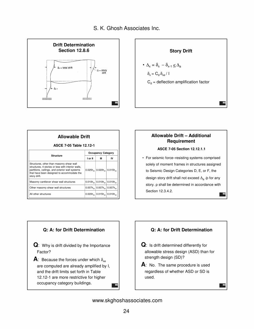
Drift Determination
Section 12.8.6Step 1: Determine δxe at each floor level
where δxe is the lateral deflection at floor
level x determined by elastic analysis
under code-prescribed seismic forces.
Step 2: Multiply δxe by Cd given in Table
12.12-1, the product representing the
estimated design earthquake
displacement.
Drift Determination
Section 12.8.6
Step 3: Divide δxeCd by I, Importance
Factor: δ x = δxeCd /I
Step 4: Determine design story drift:
∆x = δx – (δx – 1)
24
S. K. Ghosh Associates Inc.
www.skghoshassociates.com
Drift Determination
Section 12.8.6 Story Drift
• ∆x = δx − δx-1 < ∆a
δx = Cd δxe / I
Cd = deflection amplification factor
Allowable Drift
StructureOccupancy Category
I or II III IV
Structures, other than masonry shear wall
structures, 4 stories or less with interior walls, partitions, ceilings, and exterior wall systems
that have been designed to accommodate the
story drift.
0.025hsx 0.020hsx 0.015hsx
Masonry cantilever shear wall structures 0.010hsx 0.010hsx 0.010hsx
Other masonry shear wall structures 0.007hsx 0.007hsx 0.007hsx
All other structures 0.020hsx 0.015hsx 0.010hsx
ASCE 7-05 Table 12.12-1
• For seismic force–resisting systems comprised
solely of moment frames in structures assigned
to Seismic Design Categories D, E, or F, the
design story drift shall not exceed ∆a /ρ for any
story. ρ shall be determined in accordance with
Section 12.3.4.2.
Allowable Drift – Additional
Requirement
ASCE 7-05 Section 12.12.1.1
Q: A: for Drift Determination
Q: Why is drift divided by the Importance
Factor?
A: Because the forces under which δxe
are computed are already amplified by I,
and the drift limits set forth in Table
12.12-1 are more restrictive for higher
occupancy category buildings.
Q: A: for Drift Determination
Q: Is drift determined differently for
allowable stress design (ASD) than for
strength design (SD)?
A: No. The same procedure is used
regardless of whether ASD or SD is
used.

25
S. K. Ghosh Associates Inc.
www.skghoshassociates.com
Q: A: for Drift Determination
Q: Does minimum base shear need to be
considered for drift determination?
A: Yes, Section 12.8.6.1 requires that all
of the requirements of Section 12.8 be
satisfied for the purpose of computing
drift.
Q: A: for Drift Determination
Q: Does the upper-bound limitation on
period T need to be considered for drift
determination?
A: No. Section 12.8.6.2 does not require
the period to be subject to the upper
limit of CuTa for the purpose of drift
determination.
Building Separation
Section 12.12.3
12.12.3 Building Separation. All portions
of the structure shall be designed and
constructed to act as an integral unit in
resisting seismic forces unless
separated structurally by a distance
sufficient to avoid damaging contact
under total deflection as determined in
Section 12.8.6.
Building Separation
Section 12.12.3
This section applies to SDCs B
through F.
Does not address adjacent
buildings on the same property.
Does not address minimum
setback distance from property line.
Building Separation
Section 12.12.3
Code Requirement2006 IBC/
ASCE 7-05
2009 IBC/
ASCE 7-05
PORTIONS OF THE SAME STRUCTURE:
All portions of the structure shall be designed
and constructed to act as an integral unit in
resisting seismic forces unless separated
structurally by a distance sufficient to avoid
damaging contact under total deflection (δx) as
determined in Section 12.8.6.
ASCE 7-05
Section 12.12.3
(applies to all
SDCs)
ASCE 7-05
Section 12.12.3
(applies to all
SDCs)
Continued on next page
Building Separation
2009 IBC Section 1613.6.7
Code Requirement2006 IBC/
ASCE 7-052009 IBC/
ASCE 7-05
BUILDING SEPARATIONS (paraphrased):
All structures shall be separated from adjoining structures.
Separations shall allow for the maximum inelastic
displacement δM (including torsion).
Adjacent buildings on the same property shall be separated
by at least δMT where
When a structure adjoins a property line not common to a
public way, that structure shall also be set back from the
property line by at least the displacement, δM, of that
structure.
Exception: Smaller separations or property line setbacks
shall be permitted when justified by rational analyses based
on maximum expected ground motions.
No
requirement
2009 IBC
Section
1613.6.7

26
S. K. Ghosh Associates Inc.
www.skghoshassociates.com
Building Separation
2009 IBC Section 1613.6.7
Note difference between δx and δM
The deflections of Level x at the center of
mass (12.8.6),
δx = Cd δxe / I
δM = Cd δmax / I (Equation 16-44)
δmax = the maximum displacement at Level x
computed assuming Ax = 1 (12.8.4.3)
Building Separation
2009 IBC Section 1613.6.7
Building Separation
2009 IBC Section 1613.6.7
Separation of Two Adjacent Buildings
Building Separation
2009 IBC Section 1613.6.7
10″ separation
δM1 at edge = 6″
δM2 at adjacent edge = 8″
Q:A: for Building Separation
Q: ASCE 7-05 Section 12.12.3 contains the
language “sufficient to avoid damaging
contact.” What is damaging contact?
A: To avoid any contact at all, the separation
distance would have to be the arithmetic sum of
δM1 and δM2. To avoid damaging contact, ASCE
7 allows the separation distance to be the
statistical sum of δM1 and δM2, which is less than
the arithmetic sum.
Q:A: for Building Separation
Q: I do not understand the logic of
requiring less separation between two
buildings on the same property than
between two identical buildings on different
sides of the property line.

27
S. K. Ghosh Associates Inc.
www.skghoshassociates.com
Q:A: for Building Separation
A: The first provision is concerned with
damaging contact from pounding of
buildings belonging to presumably the
same owner. The property line setback
requirement is based on consideration
that one owner should not encroach
onto another property.
PROVISION#7
R, Cd and Ω0 Values forHorizontal and Vertical
Combinations
R, Cd and Ωo Values for Horizontal
and Vertical Combinations
Horizontal Combinations can be
either….
• In different directions
• In same direction
Section 12.2.2 Combinations of
Framing Systems in Different
Directions
• Different seismic force-resisting systems
may be used to resist seismic forces along
each of two orthogonal plan axes.
• The respective R, Cd, and Ωo coefficients
shall apply to each system, including the
limitations on system use contained in
Table 12.2-1.
Section 12.2.2 Combinations of
Framing Systems in Different
Directions
R =5Cd = 5Ωo = 2½
R = 8, Cd = 5 ½, Ωo = 3
Section 12.2.3 Combinations of
Framing Systems in the Same
DirectionWhere different seismic force-resisting systems
are used in combination to resist seismic
forces in the same direction of structural
response, other than those combinations
considered as dual systems, the more
stringent system limitation contained in Table
12.2-1 shall apply and the design shall comply
with the requirements of this section.

28
S. K. Ghosh Associates Inc.
www.skghoshassociates.com
12.2.3.1 Vertical Combinations
R: Cannot increase as you go down
Cd and ΩΩΩΩ0: Cannot decrease as you go down
R=8, Cd=5.5, Ω0=3
R=5, Cd=5, Ω0=2.5
8, 5.5, 3
8, 5.5, 3
8, 5.5, 3
5, 5.5, 3
5, 5.5, 3
5, 5.5, 3
R=5, Cd=5, Ω0=2.5
R=8, Cd=5.5, Ω0=3
5, 5, 2.5
5, 5, 2.5
5, 5, 2.5
5, 5.5, 3
5, 5.5, 3
5, 5.5, 3
R=5, Cd=5, Ω0=2.5
R=8, Cd=5.5, Ω0=3
5, 5.5, 3
5, 5.5, 3
5, 5.5, 3
5, 5.5, 3
R=8, Cd=5.5, Ω0=3 8, 5.5, 3
8, 5.5, 3
12.2.3.2 Horizontal Combinations
12.2.3.2 Where a combination of different structural systems is utilized to resist lateral
forces in the same direction, value of R used for design in that direction shall not be greater than the least value of R for any of the systems
utilized in that direction.
12.2.3.2 Horizontal Combinations
12.2.3.2 Resisting elements are permitted to be designed using the least value of R for the
different structural systems found in each independent line of resistance if the following three conditions are met: 1) Occupancy Category
I or II building, 2) two stories or less in height, and 3) use of light frame construction or flexible diaphragms.
The value of R used for design of diaphragms in such structures shall not be greater than the least
value for any of the systems utilized in that same direction.
12.2.3.2 Horizontal Combinations
The deflection amplification factor, Cd, and the
system overstrength factor, ΩΩΩΩ0 , in the direction
under consideration at any story shall not be
less than the largest value of this factor for the
R factor used in the same direction being
considered.
12.2.3.2 Horizontal Combinations
The second paragraph of ASCE 7-05 Section
12.2.3.2 is far from clear.
One possible interpretation is that when different
structural systems are combined in the same
direction of a building or other structure, the
largest Cd- and ΩΩΩΩ0-values of all the individual
structural systems shall be used.
12.2.3.2 Horizontal Combinations
The other possible interpretation is that the Cd-
and ΩΩΩΩ0-values shall correspond to the least R-
value of all the individual structural systems.
The second interpretation appears to be the
more logical in view of the following example
(discussion is continued in terms of Cd alone).

29
S. K. Ghosh Associates Inc.
www.skghoshassociates.com
12.2.3.2 Horizontal Combinations
Consider a rather extreme example where a
prestressed masonry shear wall (R = 1.5, Cd =
1.75) is combined with a special steel moment-
resisting frame (R = 8, Cd = 5.5). There is no
question that the R-value is 1.5. The question is
whether the Cd-value is 1.75 or 5.5. 5.5 does not
seem logical – for two reasons.
12.2.3.2 Horizontal Combinations
First, the combined system is much more rigid
than the special steel moment frame itself.
Until the prestressed masonry shear wall
hinges at its base, which is extremely unlikely
in view of the large design forces that would
result from an R = 1.5, large inelastic
displacements do not seem to be possible.
12.2.3.2 Horizontal Combinations
Second, large values of δδδδxe would automatically
result from the low value of R used in design.
These, multiplied by the Cd of 5.5 would yield
unrealistically large total displacements. Cd of
1.75 appears to be much more logical.
This second interpretation was implicit in the
1997 Uniform Building Code, where 0.7R was
used in place of Cd.
12.2.3.2 Horizontal Combinations
The proposed rewrite provides clarification of the
second paragraph of ASCE 7-05 Section
12.2.3.2. The rewrite also offers clarification
concerning another complication that may
arise, which is that different structural systems
having the same R-value sometimes have
different Cd- and ΩΩΩΩ0-values.
12.2.3.2 Horizontal CombinationsTable 12.2.3.2 R, Cd, and Ωo Values for Combination of
Different Structural Systems Used in Same Direction
R value The least value of R for any of the systems used.
Exception: Resisting elements are permitted to be designed using the
least value of R for the different structural systems found in each
independent line of resistance if the following three conditions are met: 1)
Occupancy Category I or II building, 2) two stories or less in height, and 3)
use of light frame construction or flexible diaphragms.
Cd value The Cd value corresponding to the system with the least value of R for any
of the systems used. In the case where two or more systems have the
same least value of R, the largest of the corresponding values of Cd shall be
used.
Ωo value The Ωo value corresponding to the system with the least value of R for any
of the systems used. In the case where two or more systems have the
same least value of R, the largest of the corresponding values of Ωo shall be
used.
Vertical combinations
R: Cannot increase as you go downCd and ΩΩΩΩ0: Always correspond to R
ASCE 7-10 Section 12.2.3.1 Vertical Combinations
R = 8, Cd = 5.5, Ω0 = 3
R = 5, Cd = 5, Ω0 = 2.5
8, 5.5, 3
8, 5.5, 3
8, 5.5, 3
5, 5, 2.5
5, 5, 2.5
5, 5, 2.5
R = 5, Cd = 5, Ω0 = 2.5
R = 8, Cd = 5.5, Ω0 = 3
5, 5, 2.5
5, 5, 2.5
5, 5, 2.5
5, 5, 2.5
5, 5, 2.5
5, 5, 2.5
R = 5, Cd = 5, Ω0 = 2.5
R = 8, Cd = 5.5, Ω0 = 3
5, 5, 2.5
5, 5, 2.5
5, 5, 2.5
5, 5, 2.5
R = 8, Cd = 5.5, Ω0 = 3 8, 5.5, 3
8, 5.5, 3
30
S. K. Ghosh Associates Inc.
www.skghoshassociates.com
12.2.4 Combination Framing
Detailing Requirements
Structural components common to different
framing systems used to resist seismic
motions in any direction shall be designed
using the detailing requirements of Chapter 12
required by the highest response modification
coefficient, R, of the connected framing
systems.
Q: A: for Combinations
Q: I am designing a building that has a combination of special
reinforced masonry shear walls and special steel braced frames
in the same direction. R values are 5.5 and 6, respectively. I
understand that I should design the building with the smaller R
= 5.5 for both the masonry shear walls and steel braced frames
in this direction for seismic design in accordance with ASCE 7-
05 Section 12.2.3.2. But someone told me that the building
should be designed by analyzing the entire building twice: use
R = 5.5 for the entire building to analyze and design the
masonry shear walls and use R = 6 for the entire building to
design the steel frames. I don't think this is right. What is your
thought on this?
Q: A: for Combinations
A: What you understand is correct. The latter
interpretation is unfamiliar and incorrect.
PROVISION#8
MINIMUM SEISMICBASE SHEAR
CodeMaster
2009 IBC Seismic Design
ASCE 7-05 12.8.1
Design Base Shear
31
S. K. Ghosh Associates Inc.
www.skghoshassociates.com
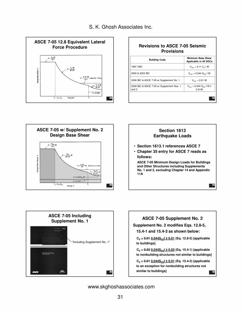
ASCE 7-05 12.8 Equivalent Lateral
Force Procedure Revisions to ASCE 7-05 Seismic
Provisions
Building CodeMinimum Base Shear
Applicable in All SDCs
1997 UBC Vmin = 0.11 Ca I W
2000 & 2003 IBC Vmin = 0.044 SDS I W
2006 IBC & ASCE 7-05 w/ Supplement No. 1 Vmin = 0.01 W
2009 IBC & ASCE 7-05 w/ Supplement Nos. 1
and 2
Vmin = 0.044 SDS I W ≥
0.01W
ASCE 7-05 w/ Supplement No. 2
Design Base ShearSection 1613
Earthquake Loads
• Section 1613.1 references ASCE 7
• Chapter 35 entry for ASCE 7 reads as
follows:
ASCE 7-05 Minimum Design Loads for Buildings
and Other Structures including Supplements No. 1 and 2, excluding Chapter 14 and Appendix 11A
ASCE 7-05 Including
Supplement No. 1
“Including Supplement No. 1”
ASCE 7-05 Supplement No. 2
Supplement No. 2 modifies Eqs. 12.8-5,
15.4-1 and 15.4-3 as shown below:
CS = 0.01 0.044SDSI ≥ 0.01 (Eq. 12.8-5) [applicable
to buildings]
CS = 0.03 0.044SDSI ≥ 0.03 (Eq. 15.4-1) [applicable
to nonbuilding structures not similar to buildings]
CS = 0.01 0.044SDSI ≥ 0.01 (Eq. 15.4-3) [applicable
to an exception for nonbuilding structures not
similar to buildings]
32
S. K. Ghosh Associates Inc.
www.skghoshassociates.com
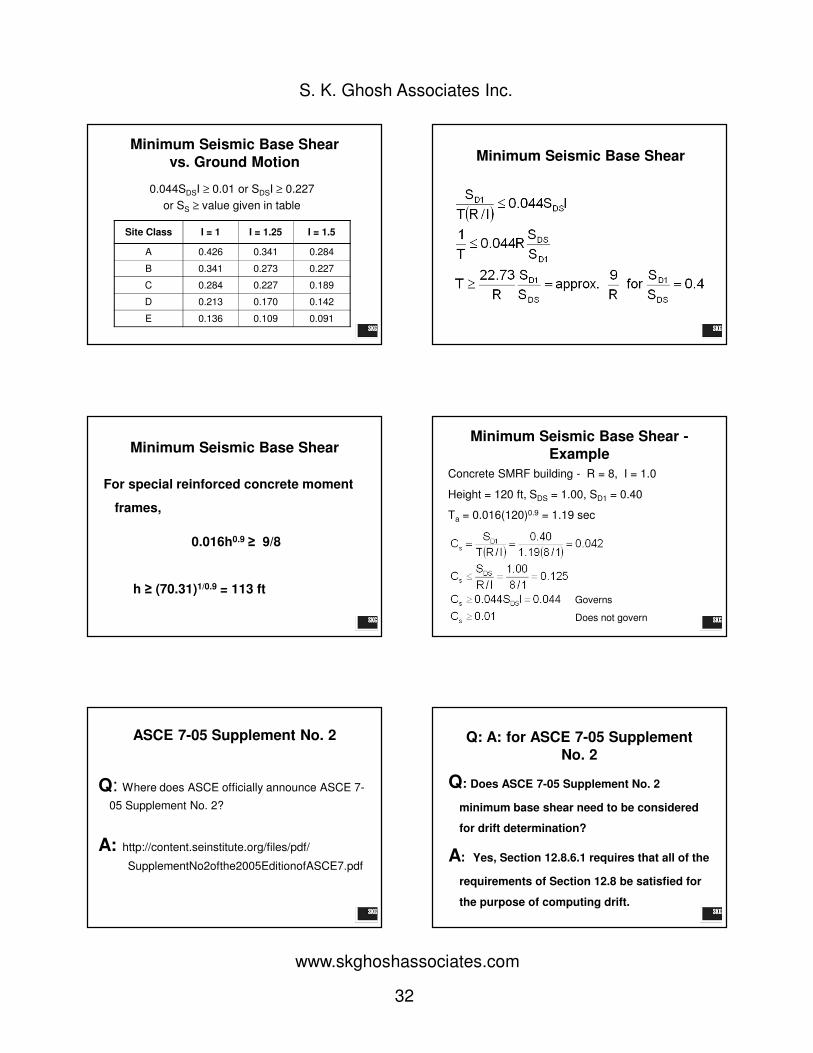
Minimum Seismic Base Shear
vs. Ground Motion
0.044SDSI ≥ 0.01 or SDSI ≥ 0.227
or SS ≥ value given in table
Site Class I = 1 I = 1.25 I = 1.5
A 0.426 0.341 0.284
B 0.341 0.273 0.227
C 0.284 0.227 0.189
D 0.213 0.170 0.142
E 0.136 0.109 0.091
Minimum Seismic Base Shear
Minimum Seismic Base Shear
For special reinforced concrete moment
frames,
0.016h0.9 ≥ 9/8
h ≥ (70.31)1/0.9 = 113 ft
Minimum Seismic Base Shear -
Example
Concrete SMRF building - R = 8, I = 1.0
Height = 120 ft, SDS = 1.00, SD1 = 0.40
Ta = 0.016(120)0.9 = 1.19 sec
Governs
Does not govern
ASCE 7-05 Supplement No. 2
Q: Where does ASCE officially announce ASCE 7-
05 Supplement No. 2?
A: http://content.seinstitute.org/files/pdf/
SupplementNo2ofthe2005EditionofASCE7.pdf
Q: A: for ASCE 7-05 Supplement
No. 2
Q: Does ASCE 7-05 Supplement No. 2
minimum base shear need to be considered
for drift determination?
A: Yes, Section 12.8.6.1 requires that all of the
requirements of Section 12.8 be satisfied for
the purpose of computing drift.

33
S. K. Ghosh Associates Inc.
www.skghoshassociates.com
Q: A: for ASCE 7-05 Supplement
No. 2
Q: Is ASCE 7-05 going to be published with
errata and Supplement No. 2 incorporated?
A: “Additional printings will, to the extent
possible, include as extra pages the
supplements and errata. However there's a
conscious decision not to integrate them
directly into the text so as to minimize
confusion between one book and another.”
PROVISION#9
FLEXIBLE VS. RIGIDDIAPHRAGMS
2006 and 2009 IBC Section 1602
Definition for Diaphragms
DIAPHRAGM
Diaphragm, blocked
Diaphragm boundary
Diaphragm chord
Diaphragm, flexible
Diaphragm, rigid
Diaphragm, unblocked
FLEXIBLE DIAPHRAGMS
Prescriptive Approach
&
Calculation Approach
2006 and 2009 IBC Section 1602
Definition for Flexible Diaphragm
Diaphragm, flexible.
A diaphragm is flexible for the purpose of distribution
of story shear and torsional moment where so
indicated in Section 12.3.1 of ASCE 7, as modified in
Section 1613.6.1.
12.3.1.1 Flexible Diaphragm
Condition. Diaphragms constructed of untopped
steel decking or wood structural panels are
permitted to be idealized as flexible in structures
in which the vertical elements are steel or
composite steel and concrete braced frames, or
concrete, masonry, steel, or composite shear
walls. Diaphragms of wood structural panels or
untopped steel decks in one- and two-family
residential buildings of light-frame construction
shall also be permitted to be idealized as flexible.
ASCE 7-05 Section 12.3.1.1
Definition for Flexible Diaphragm (Prescriptive)

34
S. K. Ghosh Associates Inc.
www.skghoshassociates.com
12.3.1.3 Calculated Flexible Diaphragm Condition. Diaphragms … are permitted to be
idealized as flexible where the computed maximum in-plane deflection of the diaphragm under lateral load is more than two times the
average story drift of adjoining vertical elements of the seismic force –resisting system of the associated story under equivalent
tributary lateral load as shown in Fig. 12.3-1.
ASCE 7-05 Section 12.3.1.3
Definition for Flexible Diaphragms by Calculation
ASCE 7-05 Figure 12.3-1
Definition for Flexible Diaphragm
by Calculation
MAXIMUM DIAPHRAGM
DEFLECTION (MDD)
AVERAGE DRIFT OF
VERTICAL ELEMENT(ADVE)
Note: Diaphragm is flexible If MDD > 2 (ADVE).
S
De
SEISMIC LOADING
2006 and 2009 IBC Section 1613.6.1
Definition for Flexible Diaphragm(Prescriptive)
1613.6.1 Assumption of flexible diaphragm. Add the following text at the
end of Section 12.3.1.1 of ASCE 7:
Diaphragms constructed of wood structural
panels or untopped steel decking shall
also be permitted to be idealized as flexible, provided four given conditions
are met…
2006 and 2009 IBC Section 1613.6.1
Definition for Flexible Diaphragm
Condition #1:
Toppings of concrete or similar materials
are not placed over wood structural
panel diaphragms except for
nonstructural toppings no greater than 1
½ inches thick.
2006 and 2009 IBC Section 1613.6.1
Definition for Flexible Diaphragm
Condition #2:
Each line of vertical elements of the
lateral force-resisting system complies
with the allowable story drift of Table
12.12-1.
2006 and 2009 IBC Section 1613.6.1
Definition for Flexible Diaphragm
Condition #3:
Vertical elements of the lateral-force-
resisting system are light-framed walls
sheathed with wood structural panels
rated for shear resistance or steel
sheets.
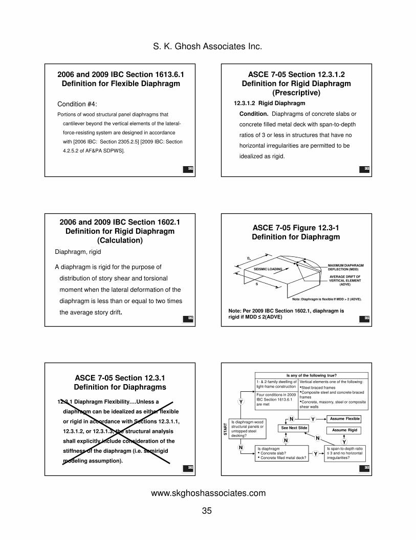
35
S. K. Ghosh Associates Inc.
www.skghoshassociates.com
2006 and 2009 IBC Section 1613.6.1
Definition for Flexible Diaphragm
Condition #4:
Portions of wood structural panel diaphragms that
cantilever beyond the vertical elements of the lateral-
force-resisting system are designed in accordance
with [2006 IBC: Section 2305.2.5] [2009 IBC: Section
4.2.5.2 of AF&PA SDPWS].
ASCE 7-05 Section 12.3.1.2
Definition for Rigid Diaphragm
(Prescriptive)
12.3.1.2 Rigid Diaphragm
Condition. Diaphragms of concrete slabs or
concrete filled metal deck with span-to-depth
ratios of 3 or less in structures that have no
horizontal irregularities are permitted to be
idealized as rigid.
2006 and 2009 IBC Section 1602.1
Definition for Rigid Diaphragm
(Calculation)
Diaphragm, rigid
A diaphragm is rigid for the purpose of
distribution of story shear and torsional
moment when the lateral deformation of the
diaphragm is less than or equal to two times
the average story drift.
ASCE 7-05 Figure 12.3-1
Definition for Diaphragm
MAXIMUM DIAPHRAGM
DEFLECTION (MDD)
AVERAGE DRIFT OF
VERTICAL ELEMENT(ADVE)
Note: Diaphragm is flexible If MDD > 2 (ADVE).
S
De
SEISMIC LOADING
Note: Per 2009 IBC Section 1602.1, diaphragm is rigid if MDD ≤ 2(ADVE)
ASCE 7-05 Section 12.3.1
Definition for Diaphragms
12.3.1 Diaphragm Flexibility….Unless a
diaphragm can be idealized as either flexible
or rigid in accordance with Sections 12.3.1.1,
12.3.1.2, or 12.3.1.3, the structural analysis
shall explicitly include consideration of the
stiffness of the diaphragm (i.e. semirigid
modeling assumption).
Is diaphragm wood structural panels or
untopped steel decking?
Is any of the following true?
1- & 2-family dwelling of
light-frame construction
Vertical elements one of the following:
•Steel braced frames
•Composite steel and concrete braced
frames
•Concrete, masonry, steel or composite
shear walls
Four conditions in 2009
IBC Section 1613.6.1
are met
Is diaphragm• Concrete slab?
• Concrete filled metal deck?
Is span-to-depth ratio ≤ 3 and no horizontal
irregularities?
Assume Rigid
Assume Flexible
See Next Slide
Y
N
NY
Y
Y
N
N
ST
AR
T

36
S. K. Ghosh Associates Inc.
www.skghoshassociates.com
MAXIMUM DIAPHRAGM
DEFLECTION (MDD)
AVERAGE DRIFT OF
VERTICAL ELEMENT(ADVE)
Is MDD > 2 (ADVE)?
S
De
SEISMIC LOADING
Assume Flexible
Y
Assume Rigid
N
PROVISION#10
Special Seismic Load Combinations
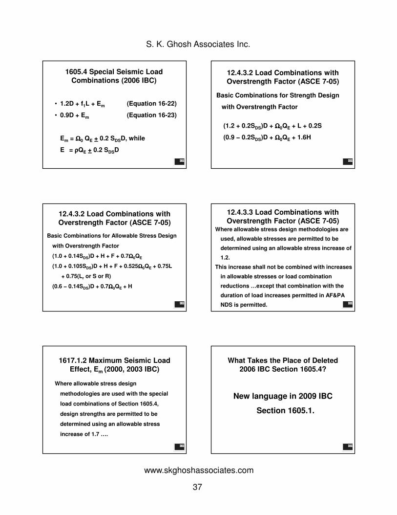
2006 IBC 1605.4 Special Seismic
Load Combinations
Section 1605.4 is deleted in its entirety in
the 2009 IBC.
SPECIAL SEISMIC LOAD COMBINATIONS
is replaced with
LOAD COMBINATIONS WITH OVERSTRENGTH FACTORS
of ASCE 7-05
Why Was 2006 IBC Section 1605.4
Deleted?
To eliminate a disconnect between IBC and
ASCE 7-05:
– 2006 IBC Section 1605.4 had one set of
“special seismic load combinations”
applicable to both ASD and strength design.
– ASCE 7-05 has two sets of “load combinations
with overstrength factors”…one for ASD and
one for strength design.
Why Was 2006 IBC Section 1605.4
Deleted?
To eliminate a disconnect between IBC and ASCE 7-
05 (cont.):
– 2006 IBC had separate, unique load
combinations that were to be applied where
specifically required.
– ASCE 7-05 prescribes an equation for Em that
is to be used in ASCE 7-05 Ch. 2 load
combinations.
37
S. K. Ghosh Associates Inc.
www.skghoshassociates.com
1605.4 Special Seismic Load
Combinations (2006 IBC)
• 1.2D + f1L + Em (Equation 16-22)
• 0.9D + Em (Equation 16-23)
Em = ΩΩΩΩ0 QE + 0.2 SDSD, while
E = ρρρρQE + 0.2 SDSD
12.4.3.2 Load Combinations with
Overstrength Factor (ASCE 7-05)
Basic Combinations for Strength Design
with Overstrength Factor
(1.2 + 0.2SDS)D + ΩΩΩΩ0QE + L + 0.2S
(0.9 − 0.2SDS)D + ΩΩΩΩ0QE + 1.6H
12.4.3.2 Load Combinations with
Overstrength Factor (ASCE 7-05)
Basic Combinations for Allowable Stress Design
with Overstrength Factor
(1.0 + 0.14SDS)D + H + F + 0.7ΩΩΩΩ0QE
(1.0 + 0.105SDS)D + H + F + 0.525ΩΩΩΩ0QE + 0.75L
+ 0.75(Lr or S or R)
(0.6 − 0.14SDS)D + 0.7ΩΩΩΩ0QE + H
12.4.3.3 Load Combinations with
Overstrength Factor (ASCE 7-05)Where allowable stress design methodologies are
used, allowable stresses are permitted to be
determined using an allowable stress increase of
1.2.
This increase shall not be combined with increases
in allowable stresses or load combination
reductions …except that combination with the
duration of load increases permitted in AF&PA
NDS is permitted.
1617.1.2 Maximum Seismic Load
Effect, Em (2000, 2003 IBC)
Where allowable stress design
methodologies are used with the special
load combinations of Section 1605.4,
design strengths are permitted to be
determined using an allowable stress
increase of 1.7 ….
What Takes the Place of Deleted
2006 IBC Section 1605.4?
New language in 2009 IBC
Section 1605.1.

38
S. K. Ghosh Associates Inc.
www.skghoshassociates.com
What Takes the Place of Deleted
2006 IBC Section 1605.4?
1605.1 General. Buildings and other structures and
portions thereof shall be designed to resist:
1. The load combinations specified in Section 1605.2,
1605.3.1 or 1605.3.2,
2. The load combinations specified in Chapters 18 through
23, and
3. The load combinations with overstrength factor
specified in Section 12.4.3.2 of ASCE 7 where required
by Section 12.2.5.2, 12.3.3.3 or 12.10.2.1 of ASCE 7.
With the simplified procedure of ASCE 7 Section 12.14,
the load combinations with overstrength factor of
Section 12. 14.3.2 of ASCE 7 shall be used.
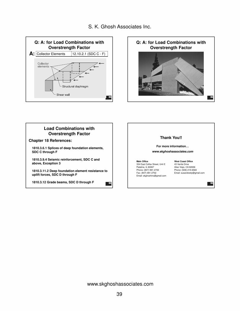
Q: A: for Load Combinations with
Overstrength Factor
Q: Section 1605.1 of the 2009 IBC requires
buildings and other structures and portions
thereof to be designed to resist the load
combinations with overstrength factor
specified in Section 12.4.3.2 of ASCE 7-05
where required by Section 12.2.5.2, 12.3.3.3, or
12.10.2.1. Can you elaborate?
Q: A: for Load Combinations with
Overstrength Factor
Cantilever Column Systems 12.2.5.2
SDC B - F
A:
Foundation and other elements used to provide overturning resistance at the base of cantilever column elements shall have the strength to resist the load combinations with over strength factor of Section 12.4.3.2.
Q: A: for Load Combinations with
Overstrength Factor
A: Elements Supporting
Discontinuous Walls or Frames
12.3.3.3
SDC B - F
Q: A: for Load Combinations with
Overstrength FactorQ: A: for Load Combinations with
Overstrength Factor
39
S. K. Ghosh Associates Inc.
www.skghoshassociates.com
Q: A: for Load Combinations with
Overstrength Factor
A: Collector Elements 12.10.2.1 (SDC C - F)
Q: A: for Load Combinations with
Overstrength Factor
Load Combinations with
Overstrength Factor
Chapter 18 References:
1810.3.6.1 Splices of deep foundation elements,
SDC C through F
1810.3.9.4 Seismic reinforcement, SDC C and above, Exception 3
1810.3.11.2 Deep foundation element resistance to uplift forces, SDC D through F
1810.3.12 Grade beams, SDC D through F
Thank You!!
For more information…
www.skghoshassociates.com
Main Office
334 East Colfax Street, Unit E
Palatine, IL 60067
Phone: (847) 991-2700
Fax: (847) 991-2702
Email: [email protected]
West Coast Office
43 Vantis Drive
Aliso Viejo, CA 92656
Phone: (949) 215-6560
Email: [email protected]

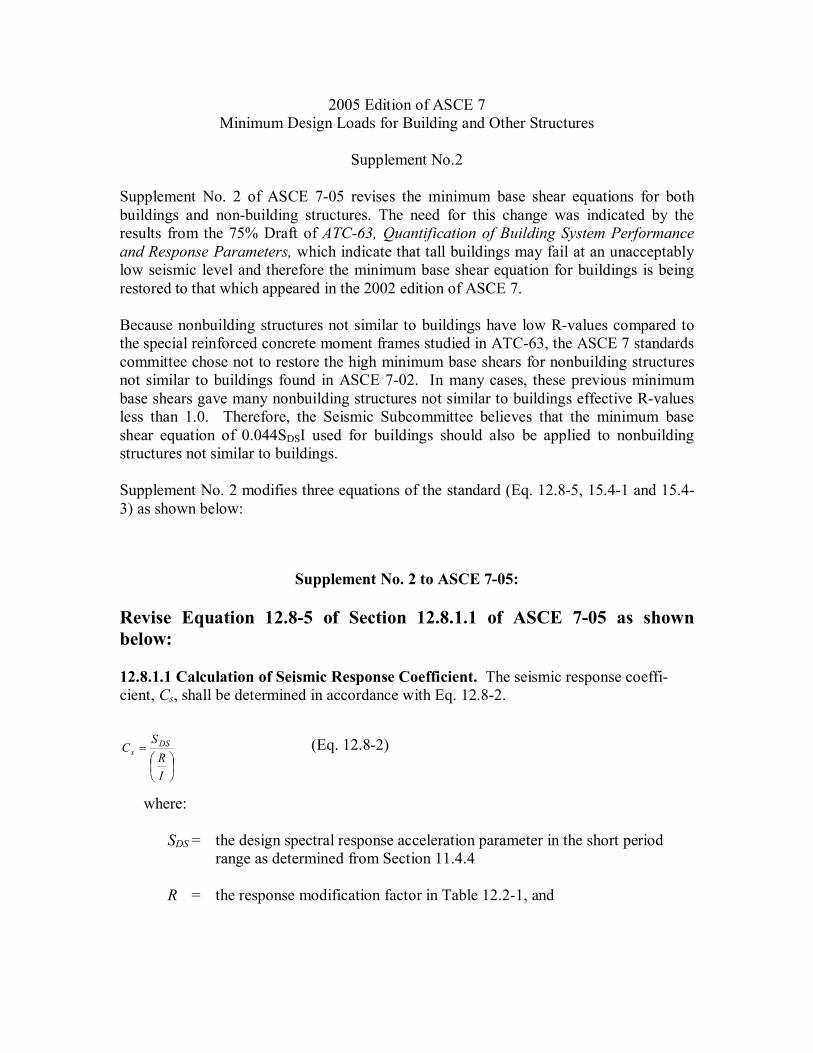
2005 Edition of ASCE 7 Minimum Design Loads for Building and Other Structures
Supplement No.2
Supplement No. 2 of ASCE 705 revises the minimum base shear equations for both buildings and nonbuilding structures. The need for this change was indicated by the results from the 75% Draft of ATC63, Quantification of Building System Performance and Response Parameters, which indicate that tall buildings may fail at an unacceptably low seismic level and therefore the minimum base shear equation for buildings is being restored to that which appeared in the 2002 edition of ASCE 7.
Because nonbuilding structures not similar to buildings have low Rvalues compared to the special reinforced concrete moment frames studied in ATC63, the ASCE 7 standards committee chose not to restore the high minimum base shears for nonbuilding structures not similar to buildings found in ASCE 702. In many cases, these previous minimum base shears gave many nonbuilding structures not similar to buildings effective Rvalues less than 1.0. Therefore, the Seismic Subcommittee believes that the minimum base shear equation of 0.044SDSI used for buildings should also be applied to nonbuilding structures not similar to buildings.
Supplement No. 2 modifies three equations of the standard (Eq. 12.85, 15.41 and 15.4 3) as shown below:
Supplement No. 2 to ASCE 705:
Revise Equation 12.85 of Section 12.8.1.1 of ASCE 705 as shown below:
12.8.1.1 Calculation of Seismic Response Coefficient. The seismic response coeffi cient, Cs, shall be determined in accordance with Eq. 12.82.
=
I R S
C DS s (Eq. 12.82)
where:
SDS = the design spectral response acceleration parameter in the short period range as determined from Section 11.4.4
R = the response modification factor in Table 12.21, and

I = the occupancy importance factor determined in accordance with Section 11.5.1
The value of Cs computed in accordance with Eq. 12.82 need not exceed the following:
L 1 D
s T T for
I R T
S C ≤
= (Eq. 12.83)
L 2
L 1 D s T T for
I R T
T S C >
= (Eq. 12.84)
Cs shall not be less than
Cs = 0.01 0.044SDSI ≥ 0.01 (Eq. 12.85)
In addition, for structures located where S1 is equal to or greater than 0.6g, Cs shall not be less than
=
I R S . C s 1 5 0 (Eq. 12.86)
where I and R are as defined in Section 12.8.1.1 and
SD1 = the design spectral response acceleration parameter at a period of 1.0 sec, as determined from Section 11.4.4
T = the fundamental period of the structure (sec) determined in Section 12.8.2
TL = longperiod transition period (sec) determined in Section 11.4.5 S1 = the mapped maximum considered earthquake spectral
response acceleration parameter determined in accordance with Section 11.4.1
Revise Equations 15.41 and 15.42 of Section 15.4.1, item 2, as shown below:
2. For nonbuilding systems that have an R value provided in Table 15.42, the seismic response coefficient (Cs) shall not be taken less than
Cs = 0.03 0.044SDSI ≥ 0.03 (15.41)
and for nonbuilding structures located where S1 ≥ 0.6g, Cs shall not be taken less than

=
I R S C s 1 8 . 0 (15.42)
EXCEPTION: Tanks and vessels that are designed to AWWA D100, AWWA D103, API 650 Appendix E, and API 620 Appendix L as modified by this standard, shall be subject to the larger of the minimum base shear values defined by the reference document or the following equations:
Cs = 0.01 0.044SDSI ≥ 0.01 (15.43)
and for nonbuilding structures located where S1 ≥ 0.6g, Cs shall not be taken less than
=
I R S C s 1 5 . 0 (15.44)
Minimum base shear requirements need not apply to the convective (sloshing) component of liquid in tanks.