s e s g s g e u p qa/q i g v - home - energy home upgrade inspection novemberguidelines v5.0 2014 i...
TRANSCRIPT

SOUTHERN CALIFORNIA EDISON &
SOUTHERN CALIFORNIA GAS COMPANY
SOUTHERN CALIFORNIA GAS COMPANY
ENERGY UPGRADE CALIFORNIA®
HOME UPGRADE PROGRAM
QA/QC INSPECTION GUIDELINES
VERSION 5.0

QA/QC Inspection Guidelines v5.0 November 2014
i i
Table of Contents
Section 1: Document Purpose and Application .............................................................................................. 3
Section 2: Order of Inspection Procedures ...................................................................................................... 4
Section 3: Combustion Appliance Safety (CAS) Testing .............................................................................. 6
A. General CAS/CAZ Testing Guidelines (all appliances): ....................................................................6
B. Special CAS Considerations for 2-4 Unit Buildings ............................................................................7
C. General Visual Inspection of Appliances: ...............................................................................................8
D. CAS Testing in Conjunction with CAZ Testing: ....................................................................................9
Section 4: Combustion Appliance Zone (CAZ) Testing .............................................................................. 10
A. CAZ Depressurization Testing Non-Feasibility Criteria: .............................................................. 10
B. Baseline Procedure:...................................................................................................................................... 10
C. Worst Case Depressurization (WCD) Test Procedure:.................................................................. 11
D. Furnace CAS Testing: ................................................................................................................................... 11
E. Hydronic FAU CAS Testing: ....................................................................................................................... 13
F. Water Heater (DHW) CAS Testing: ........................................................................................................ 13
G. Open Combustion Gas Log Fireplace CAS Testing: ......................................................................... 15
H. Insert Fireplace CAS Testing: ................................................................................................................... 15
I. Gas Range / Cooktop CAS Testing: ......................................................................................................... 16
J. Oven CAS Testing: ......................................................................................................................................... 16
K. Separate Broiler CAS Testing: .................................................................................................................. 17
L. Dryer CAS Testing: ........................................................................................................................................ 18
M. Carbon Monoxide Monitors/Alarms: .................................................................................................... 18
Section 5: Combustion Ventilation Air (CVA) ............................................................................................... 19
A. CVA Basics: ....................................................................................................................................................... 19
B. Definitions: ....................................................................................................................................................... 19
C. CVA Vent and Duct Criteria: ...................................................................................................................... 20
D. CVA Calculations: ........................................................................................................................................... 21
E. Area Calculations for Round Combustion Air Vents and Ducts: ................................................ 22
F. Reduction Factors: ........................................................................................................................................ 23
Section 6: Duct Leakage Testing ....................................................................................................................... 24
A. Dust Test Non-Feasibility Criteria: ........................................................................................................ 24
B. Duct Leakage Testing Considerations for 2-4 Unit Buildings: .................................................. 24
C. Leakage to Outside Test Procedure: ...................................................................................................... 24
D. Cruise Control: ................................................................................................................................................ 28
Section 7: Building Air Leakage Testing ........................................................................................................ 29
A. Non-Feasibility Criteria: ............................................................................................................................. 29
B. Building Air Leakage Testing Considerations for 2-4 Unit Buildings: .................................... 29
C. Positive Pressure Blower Door Test Set-up and Procedure: ...................................................... 29
D. Negative Pressure Blower Door Test Set-up and Procedure: .................................................... 31

QA/QC Inspection Guidelines v5.0 November 2014
2
Energy Upgrade California® Home Upgrade Program
Section 8: HVAC and DHW Systems Data Collection .................................................................................. 34
A. Heating Systems: ........................................................................................................................................... 34
B. Cooling Systems: ............................................................................................................................................ 34
C. Duct Systems: .................................................................................................................................................. 35
D. Domestic Hot Water (DHW) Systems: .................................................................................................. 35
Section 9: Insulation Requirements and Inspection Procedures ......................................................... 37
A. Attic Insulation Non-Feasibility: ............................................................................................................. 37
B. Heat Producing Devices (HPDs): ............................................................................................................ 37
C. Knob-and-Tube Wiring: .............................................................................................................................. 38
D. Indoor Air Quality (IAQ):............................................................................................................................ 39
E. Attic Insulation Inspection: ....................................................................................................................... 40
F. Wall Insulation Inspection: ....................................................................................................................... 41
G. Floor Insulation Inspection: ...................................................................................................................... 41
Section 10: Exterior Window and Door Data Collection ....................................................................... 42
A. Windows: .......................................................................................................................................................... 42
B. Doors: ................................................................................................................................................................. 42
C. Skylights: ........................................................................................................................................................... 42
Section 11: Miscellaneous Inspection Data ............................................................................................... 43
A. Cool Roof: .......................................................................................................................................................... 43
B. Whole House Fan (WHF): .......................................................................................................................... 43
C. Energy Efficient Ducted Evaporative Cooling Systems (EEDECS): .......................................... 43
D. Pool and Spa Heaters: .................................................................................................................................. 43
E. Pool and Spa Pumps: .................................................................................................................................... 43
F. Energy Star Labeled Ceiling Fans with Energy Star CFL(s): ....................................................... 44
G. Inspection Recap: .......................................................................................................................................... 44
Section 12: Photographs and House Sketch .............................................................................................. 45
Appendix A: Vintage Default Table ................................................................................................................. 46
Appendix B: Default BTU/Hour Ratings ........................................................................................................ 49
Appendix C: Spillage and Draft Test Processes .......................................................................................... 50
Appendix D: SoCalGas® Undiluted CO Action Levels ................................................................................. 51
Appendix E: SoCalGas® Ambient CO Action Levels.................................................................................... 52
Appendix F: CO Action Levels Compared...................................................................................................... 53
Appendix G: NOx Rod Furnace Identification and Inspection Procedure ......................................... 55
Appendix H: Advisory Conditions .................................................................................................................... 60
Appendix I: Guidance on Pre-Installation Duct Testing ......................................................................... 61
Appendix J: Clarification on Blower Door Testing in the Presence of Asbestos Containing
Materials ............................................................................................................................................... 63
Appendix K: Guidance on Fireplaces and Blower Door Testing ........................................................... 65
Appendix L: Guidance on Standards Conflicts with Local Program Rules, Law or Code ............. 66
Appendix M: Notice of Unsatisfactory Condition Form............................................................................. 68
Appendix N: C-10 Knob and Tube Wiring Survey Form .......................................................................... 69
Appendix O: Knob and Tube Caution Sign .................................................................................................... 70
Appendix P: Processing Guidelines ................................................................................................................ 71

QA/QC Inspection Guidelines v5.0 November 2014
3
Energy Upgrade California® Home Upgrade Program
Section 1: Document Purpose and Application
The procedures and specifications presented in this document are intended as a guide to QC
inspectors and contractors for completing a thorough site inspection of single-family Energy
Upgrade California® Home Upgrade, Advanced Home Upgrade and Multi-Unit (two – four) Advanced
Home Upgrade projects. The procedures are at times inter-related (as with Combustion Appliance
Safety testing and Combustion Appliance Zone testing) and should generally be followed in the
order presented below.
All Multi-Unit (two – four) buildings will be inspected in accordance with the Energy Upgrade
California Advanced Home Upgrade Single Family Inspection Guidelines. Additional requirements
for multi-unit buildings with regards to health and safety inspections, combustion appliance safety
and diagnostic testing of attached dwelling units affected by shell measures completed in project
units are described in Sections 3.B, 6.B and 7.B.

QA/QC Inspection Guidelines v5.0 November 2014
4
Energy Upgrade California® Home Upgrade Program
Section 2: Order of Inspection Procedures 1. Gas Leak Testing: All accessible interior and exterior gas lines (including the gas meter and all
fittings at the meter) must be checked for leaks prior to performing combustion appliance safety or diagnostic testing. Closely examine the following: gas meter, line valves, gas control valves, pilot lines, joints, fittings and anywhere gas lines are accessible.
a. Leaks will be detected using an electronic leak detector at 1” per one second. If a potential leak is identified, it will be confirmed with micro leak detector solution.
b. Gas lines and connections that are inaccessible to electronic leak detectors and micro leak detector solution will be subjected to olfactory testing. If odors consistent with gas leaks are detected by the inspector, a gas leak will be deemed to be present.
c. If a gas leak is found advise the customer to notify the gas company immediately. Do not perform any combustion appliance safety tests or diagnostic testing until the leak is repaired or isolated.
d. If a gas leak is found and can be isolated:
1) Close the line valve and retest in same place where the gas leak was found with micro leak detector solution.
2) If leak is no longer present, proceed with combustion safety and diagnostic testing.
3) DO NOT TURN ON A COMBUTION APPLIANCE THAT HAS A GAS LEAK.
e. If a gas leak cannot be isolated, mark the location of the gas leak by tying a brightly colored string around the pipe at the leak site.
f. After a gas leak has been repaired:
1) An additional gas leak test will be conducted to verify that the leak has been repaired and that no other leaks are present.
2) If gas leaks are no longer present, proceed with combustion safety and diagnostic
testing.
2. Special Gas Leak Testing Considerations for Multi-Unit (two-four) Buildings
a. Gas leak testing of attached dwelling units affected by shell measures completed in project
units is required.
b. Gas leak testing of project unit and attached units shall follow the procedure outlined in
section 2.1 above.
c. If a gas leak is identified in the project unit or an attached unit and cannot be isolated,
diagnostic testing of the project unit and attached units shall not proceed.
3. Check for presence of hazardous materials or any other health and safety concerns in the attic, crawl space, basement, interior and the exterior of home including:
a. Possible asbestos containing materials (PACM)
b. Black organic material
c. Knob and Tube wiring
d. Any other hazardous materials or conditions
4. Conduct Combustion Appliance Zone (CAZ) and Combustion Appliance Safety (CAS) testing.

QA/QC Inspection Guidelines v5.0 November 2014
5
Energy Upgrade California® Home Upgrade Program
a. Perform visual inspection of all appliances.
b. Conduct CAZ Depressurization Testing.
c. Conduct Combustion Appliance Safety Testing.
d. Calculate Combustion Ventilation Air (CVA) requirements for each Combustion Appliance Zone (CAZ). Determine if current CVA is adequate for each CAZ.
5. Conduct diagnostic testing.
6. Collect all remaining field data as required.

QA/QC Inspection Guidelines v5.0 November 2014
6
Energy Upgrade California® Home Upgrade Program
Section 3: Combustion Appliance Safety (CAS) Testing NOTE: Whenever a safety issue is identified, the data must be recorded and the homeowner must be
informed. A Notice of Unsatisfactory Condition must be filled out and signed by the homeowner. A copy
will be given to the homeowner and the file will be uploaded into Vision.
A. General CAS/CAZ Testing Guidelines (all appliances):
1. All natural gas and propane appliances are subject to full combustion appliance safety testing.
2. Non-gas fueled appliances (i.e. wood fireplaces, electric water heaters, electric furnaces, electric
appliances) do not require CAS testing.
3. All combustion appliances located in conditioned space, unconditioned space, utility room,
attached garage, attic, crawl-space or outside storage closet with structural framing connected
to the house or in any location that may have a direct effect on the living space are subject to full
combustion appliance safety testing.
4. Non-operational combustion appliances remain subject to gas leak inspection, vent system
inspection, CVA calculations and all other feasible test measures.
5. Combustion appliances that fail gas leak inspection remain subject to vent system inspection,
CVA calculations and all feasible test measures that do not require operation of the appliance.
6. When suspected hazardous materials or conditions are identified, all combustion appliances
remain subject to feasible CAS testing (gas leak testing, visual inspection, etc.) that does not
require appliance operation or CAZ depressurization.
7. Do not conduct CAS/CAZ testing when customer refuses.
8. Gas Leak Testing: All accessible interior and exterior gas lines (including the gas meter and all
fittings at the meter) must be checked for leaks prior to performing combustion appliance safety
testing or diagnostic testing. Closely examine the following: gas meter, regulator, line valves, gas
control valves, pilot lines, joints, fittings and anywhere gas lines are accessible. (See Section 1.1
for gas leak testing procedures).
9. Any sign of an appliance defect that presents an immediate danger to the homeowner or
inspector requires immediate shutdown of the unit (i.e.: cracked heat exchangers, severe
delayed ignition, gas leaks).
10. CO ambient levels must be monitored at all times by a personal CO detector and shall not exceed
35 parts per million. (See Appendices C and D for SoCalGas® CO action levels.)
11. Prohibited Appliance Installations:
a. No gas appliances shall be located in a sleeping area, unless:
1) Appliance is a properly set-up sealed combustion system that draws its combustion air
from outdoors.
2) Appliance is in an enclosed weather-stripped closet with a self-closing door and meets
all current code requirements.
b. No unvented combustion space heaters are allowed within the living space.

QA/QC Inspection Guidelines v5.0 November 2014
7
Energy Upgrade California® Home Upgrade Program
c. No unvented fireplaces are allowed. (Illegal in California)
d. No recall appliances are permitted. (see Appendix F: NOx Rod Furnace Identification and
Inspection Procedure)
e. An open combustion appliance with a standing pilot cannot be installed in an attic when a
whole house fan is present.
12. When the equipment is part of the participating contractor’s scope of work, all possible sources
of ignition (gas appliances, electrical outlets, condensing units, electrical panels, telephone line
connections, cable line connections, millivolt systems, etc.) located outdoors must not be located
within the Red Work Zone.
13. All unattended combustion appliances shall be inspected for sufficient Combustion Ventilation
Air (CVA). Sufficient CVA is required for appliances located in a confined space (see Section 4 for
additional information on CVA).
14. Pertaining to new installations, it is the contractor’s responsibility to verify that appliance
venting, appliance location and installed configurations conform to manufacturer’s instructions
and comply with current state and local codes.
B. Special CAS Considerations for Multi-Unit (two – four) Buildings
1. At the conclusion of the project, all natural gas heating and domestic hot water heating
appliances for all attached unit(s) must either be:

QA/QC Inspection Guidelines v5.0 November 2014
8
Energy Upgrade California® Home Upgrade Program
a. Power vented or closed combustion.
b. Moved outside the building shell (including attached garages, attics and crawl spaces).
c. Sealed off from the living space such that there is adequate combustion ventilation air for
natural gas appliance(s) and combustion gases are exhausting properly.
2. Combustion appliance safety testing will be required for all attached units.
C. General Visual Inspection of Appliances:
1. Visual inspection of the vent system, heat exchanger, burners and safety features must be
conducted.
2. Appliances shall not have defective or missing components or improper alterations.
3. All safety features must be functioning properly; i.e. spill switches, roll out switches, combustion
chamber switches, etc.
4. A proper flex connector must be installed:
a. There shall be no kinks or visible signs of corrosion.
b. No copper or soldered flex lines are allowed.
c. No flex lines manufactured before 1973 are allowed (the date is stamped on the ring
attached to the flex connector).
d. FAU flex connectors must terminate outside of the FAU cabinet.
5. A complete inspection of the vent system is required:
a. Vent system must be aligned properly and connected securely.
b. Vent defects must be identified:
1) Disconnections, leaks and obstructions.
2) Missing/defective vent cap.
3) Defective, multiple or misaligned draft diverters (draft hoods) are not permitted.
4) Excessive deterioration, rust or holes in the draft diverter
5) Single wall vent pipe where double wall is required.
c. All vent systems shall meet proper clearance requirements with adherence to SoCalGas®
standards.
1) Proper clearance from combustible materials.
2) Vents within 4’ of a wall or window must terminate 2’ above the highest eave.
3) Vents not within 4’ of a wall or window may terminate 1’ above the roof line.
4) When an evaporative cooler is present, a vent system must terminate 10’ away or 3’
above the cooler.
i. Exceptions: furnace vent termination clearance is not required under any of the
following conditions:

QA/QC Inspection Guidelines v5.0 November 2014
9
Energy Upgrade California® Home Upgrade Program
(a) The cooler and/or discharge openings are equipped with covers.
(b) The cooler shares the duct system with the FAU and a functional damper that
isolates the cooler from the duct system during the heating season is present.
(c) When a cover or damper-related exception applies, the occupants shall be
advised by the contractor to do the following, as applicable, during the heating
season:
(i) Keep the cover(s) in place during the heating season.
(ii) Keep the damper completely closed during the heating season to isolate the
cooler from the duct system.
6. A Burner-Off inspection (Cold Check) will be performed on open combustion appliances for the
following:
a. A visually-detected crack or other evidence of defects in heat exchanger or burners.
b. Other evidence of defective heat exchanger or burners: cracks, soot, rust, etc.
7. A Burner-On inspection (Hot Check) will be performed on open combustion appliances for the
following:
a. Delayed Ignition.
b. Excessive flame roll-out.
c. Abnormal flame characteristics.
1) Flame interference caused by the air handler in an FAU.
2) Flickering burner.
3) Yellow flame (more than 50% yellow, when burner is not designed to burn yellow)
4) Smothering flame (flame recirculation)
5) Lifting Flame
6) Soft lazy flame.
d. A visually-detected crack in heat exchanger or burners.
e. Other evidence of defective heat exchanger or burner: flame impingement, etc.
D. CAS Testing in Conjunction with CAZ Testing:
1. Furnace, Water Heater and Fireplace CAS Testing shall be done in conjunction with CAZ worst
case depressurization testing when applicable.
a. Spillage, Draft, Ambient CO and Undiluted CO will be measured under worst case
depressurization. See Section 3 - CAZ Testing below.
b. If Spillage, draft or undiluted CO fail under worst case depressurization, the tests will be
repeated under natural conditions once the vent stack has had adequate time to cool.
c. Appliance ambient CO test will be performed prior to undiluted CO testing when applicable.
2. See Sections 3.D-L below for CAS testing procedures specific to appliance types.

QA/QC Inspection Guidelines v5.0 November 2014
10
Energy Upgrade California® Home Upgrade Program
Section 4: Combustion Appliance Zone (CAZ) Testing NOTE: Gas leak testing and visual inspection of all vent systems, heat exchanger, burners and safety
features must be conducted prior to CAZ depressurization testing. (see Section 2 - CAS Testing above)
A. CAZ Depressurization Testing Non-Feasibility Criteria:
1. CAZ depressurization testing applies when combustion appliances are installed in the house,
attic, crawl space, or attached garage.
2. CAZ depressurization testing does not apply when appliances are installed outside in an area or
enclosure that does not have a direct effect on the living space, or in a detached garage.
3. CAZ depressurization testing does not apply to gas ranges or ovens.
4. Do not conduct CAZ depressurization testing if:
a. PACM, gas leaks or any other hazardous materials are present.
b. Heat exchanger or burner(s) are cracked, or there is another major defect to a heat
exchanger or burner which may impose an immediate threat to the safety of the homeowner
or the inspector.
c. Customer refuses.
B. Baseline Procedure:
NOTE: The following test procedures below use Minneapolis brand testing equipment. See
manufacturer’s instruction manuals for testing procedures specific to other brands of equipment.
1. The Baseline Pressure (the pressure difference between indoors and outdoors caused by stack
and wind effects) shall be determined prior to conducting CAZ testing.
a. Setting up the House for baseline pressure measurement:
1) Close all exterior doors, windows and CAZ doors.
2) Open all interior doors.
3) Turn off all exhaust fans.
4) When a fireplace is present close the damper if applicable.
5) Set all the combustion appliances to pilot and turn off the service disconnect of the FAU
or the thermostat.
b. Setting up the manometer:
1) Set the manometer Mode to PR/PR (Pressure/Pressure).
2) Connect a hose to the top right (Channel B Input) and extend the hose into the CAZ
being tested, or leave Channel B Input open if manometer is within the CAZ.
3) A reference hose shall be run from the bottom right (Channel B Reference) to outside
through the hole provided in the blower door, or through a window or other gap/crack.
Temporarily seal the gap with tape.
c. Baseline the manometer:

QA/QC Inspection Guidelines v5.0 November 2014
11
Energy Upgrade California® Home Upgrade Program
1) Press Baseline.
2) Press Start.
3) Wait 10 seconds and then press Enter.
2. Repeat baseline process for each CAZ.
C. Worst Case Depressurization (WCD) Test Procedure:
1. Ambient CO levels shall be monitored in the CAZ at all times and shall not exceed 35 PPM.
2. Setting up the House:
a. Turn on all exhaust fans (except for evaporative coolers and whole house fans).
b. Make sure the dryer is empty and clean the dryer lint screen. Set the dryer to air only and
the run time for 20-30 minutes (this allows you enough time to complete the WCD test).
c. All exterior doors and windows are to remain closed.
d. Position all interior doors to make the main body of the house more negative With Respect
To (WRT) outside.
e. If an FAU is present in the home:
1) Remove the FAU filter(s) if dirty.
2) Turn the FAU(s) fan(s) on high and determine which rooms are under negative pressure
WRT the main body of the house using a manometer with a tube attached to the top left
(Channel A Input) and extending to the room side of the closed door. Leave the bottom
left (Channel A Reference) open as it refers to the main body of the house.
3) All rooms under negative pressure WRT main body of house shall be opened during
WCD testing.
4) NOTE: in some cases WCD for a particular CAZ may occur when the FAU fan is OFF. Test
to confirm.
3. Setting up the Manometer:
a. The manometer should be set in the PR/PR Mode.
b. Leave the top right (Channel B Input) open to the CAZ.
c. A reference hose shall be run from the bottom right (Channel B Reference) to outside
through a window or other gap/crack. Temporarily seal the gap with masking tape.
4. Record the WCD result for each CAZ.
5. WCD limits will adhere to BPI Technical Standards.
D. Furnace CAS Testing:
1. Ambient CO levels shall be monitored in the CAZ at all times and shall not exceed 35 PPM.
2. Conduct gas leak inspection of accessible gas lines, valves and connections. (see Section 1.1
above).
3. Conduct visual inspection of appliance and venting. (see Section 2A-B above).

QA/QC Inspection Guidelines v5.0 November 2014
12
Energy Upgrade California® Home Upgrade Program
4. When a vent system is shared by multiple appliances the unit with the smallest BTU rating shall
be tested first and remaining appliances tested in order of increasing BTU input rate (this
applies to spillage, draft and CO testing).
5. Conduct spillage testing of natural draft systems:
a. Test for spillage under WCD to pass within 60 seconds after start-up.
b. If the unit fails spillage under WCD at 60 seconds, leave the system operating and retest
after 5 minutes under WCD.
c. If the unit fails spillage under WCD at 5 minutes, turn off the unit, wait for vent to cool
adequately and retest spillage under natural conditions at 60 seconds.
d. If the unit fails spillage under natural conditions at 60 seconds, leave the system operating
and retest after 5 minutes under natural conditions.
e. See Appendix C: Spillage and Draft Test Processes
6. Conduct draft testing of natural draft systems under WCD:
a. Draft testing shall be measured at steady-state operating conditions.
b. Draft pressure shall be taken 12-24” after the diverter or first elbow in a straight section of
the flue (minimum 18” in length).
c. Test the draft pressure:
1) Insert a static pressure probe into a vent test port so that probe openings are
perpendicular to the exhaust flow in the vent.
2) Connect the probe to a manometer tube attached to the top left (Channel A Input) of the
manometer in PR/PR mode. The bottom left (Channel A Reference) shall be left open in
reference to the CAZ.
d. If the unit fails draft under WCD, re-test under Natural Conditions once the vent stack has
had adequate time to cool.
e. All draft pressure limits will adhere to BPI Technical Standards
f. Do not drill test holes into high-efficiency (PVC) vent systems.
g. QC does not drill holes into any vent systems.
h. See Appendix C: Spillage and Draft Test Processes
7. Conduct undiluted CO test (if applicable), appliance ambient CO testing and supply register CO
testing. (See Appendices D and E for SoCalGas® CO action levels.):
a. CO testing shall be measured at steady-state operating conditions. Heating appliance shall
be operated for a minimum of 5 minutes.
b. All other appliances shall remain off.
1) Exception: Water heater pilot may be operating, but main burner shall NOT be
operating.
c. Undiluted and appliance ambient CO tests are measured under CAZ worst case
depressurization.

QA/QC Inspection Guidelines v5.0 November 2014
13
Energy Upgrade California® Home Upgrade Program
d. If the unit fails undiluted CO or appliance ambient CO test under WCD, retest under natural
conditions.
e. Undiluted and Ambient CO must be below SoCalGas® action levels.
f. Undiluted CO test procedure:
1) On natural draft furnaces, undiluted CO shall be measured before dilution air.
i. Natural draft FAUs: measure undiluted CO in the secondary air port.
ii. Natural draft wall furnaces, floor furnaces and vented room heaters: measure
undiluted CO at the draft diverter before dilution air.
g. Ambient CO Test procedure:
1) Ducted FAU systems require supply register CO testing. Any supply register CO reading
greater than 1 PPM over the ambient zone CO is considered hazardous.
i. Supply register ambient CO test procedure:
(a) Properly ventilate the home until the indoor ambient reading is equal to the
outdoor ambient reading.
(b) Measure ambient CO with a test probe inserted into the airflow in the supply
register nearest the FAU.
2) Non-ducted systems (direct vent, vented room heaters, wall and floor furnaces, free-
standing heaters, open combustion gas log fireplaces and fireplace inserts) require an
appliance ambient CO test in the atmosphere just above the unit.
i. If appliance ambient CO is ≥ 2 ppm on any heating appliance other than an FAU,
retest under Natural Conditions.
8. Verify isolation of return air (look for potential communication between return air and
combustion air).
9. Turn off the unit and clean up appropriately (put the filter back in place if it was removed).
E. Hydronic FAU CAS Testing:
1. CAS testing will take place at the boiler which generates heat to the FAU coil (see Section 3A
below).
2. Combined Hydronic Systems (FAU systems that share a heat source with the domestic hot water
of the home) must have an isolation valve and back flow preventer between domestic hot water
and space heating distribution.
a. Dedicated Hydronic systems do not require an isolation valve.
F. Water Heater (DHW) CAS Testing:
1. Ambient CO levels shall be monitored in the CAZ at all times and shall not exceed 35 PPM.
2. Conduct gas leak inspection of accessible gas lines, valves and connections. (see Section 1.1
above).
3. Conduct visual inspection of appliance and venting. (see Section 2A-B above).

QA/QC Inspection Guidelines v5.0 November 2014
14
Energy Upgrade California® Home Upgrade Program
4. Verify that DHW has been installed so that the burner and burner ignition devices are at a minimum 18” height above the garage floor (not required when unit is Flammable Vapor Ignition Resistant (FVIR) type).
5. Inspect DHW tank and appliance exterior for any defects (tank leaks, evidence of flame rollout)
6. Verify that a temperature & pressure relief valve is installed and is not capped.
7. Conduct spillage testing of natural draft systems under WCD:
a. When a vent system is shared by multiple appliances the unit with the smallest BTU rating
shall be tested first and remaining appliances tested in order of increasing BTU input rate
(this applies to spillage, draft and CO testing).
b. Turn on the DHW.
c. Test for spillage to pass within 60 seconds after start-up.
1) If the unit fails spillage under WCD at 60 seconds, leave the system operating and retest
after 5 minutes under WCD.
2) If the unit fails spillage under WCD at 5 minutes, turn off the unit, wait for vent to cool
adequately and retest spillage under natural conditions at 60 seconds.
3) If the unit fails spillage under natural conditions at 60 seconds, leave the system
operating and retest after 5 minutes under natural conditions.
8. Conduct draft testing of natural draft systems under WCD:
a. Draft testing shall be measured at steady-state operating conditions.
b. Draft pressure shall be taken 12-24” after the diverter or first elbow
c. Test the draft pressure:
1) Insert a static pressure probe so that probe openings are perpendicular to the exhaust
flow in the vent.
2) Connect the probe to a manometer tube attached to the top left (Channel A Input) of the
manometer in PR/PR mode. The bottom left (Channel A Reference) shall be left open in
reference to the CAZ.
a. If the unit fails draft under WCD, retest under Natural Conditions once the vent stack has
had adequate time to cool.
d. All draft pressure limits will adhere to BPI Technical Standards
e. Do not drill test holes into high-efficiency (PVC) vent systems.
f. Do not drill test holes into tankless water heater vent systems.
g. QC does not drill holes into any vent systems.
9. Conduct undiluted CO and appliance ambient CO testing. (See Appendices C and D for SoCalGas®
CO action levels.):
NOTE: CO testing is not required on outdoor domestic water heaters installed on an outside
wall or in an enclosure where all CVA requirements have been met, unless the enclosure is
directly connected to the house with structural framing or the appliance is located
anywhere that may have a direct effect on the living space.

QA/QC Inspection Guidelines v5.0 November 2014
15
Energy Upgrade California® Home Upgrade Program
a. CO testing shall be measured at steady-state operating conditions. Water heater shall be
operated for a minimum of 5 minutes.
b. All other gas appliances shall remain off.
c. Undiluted and appliance ambient CO tests are measured under CAZ worst case
depressurization.
d. On natural draft systems, undiluted CO shall be measured before dilution air.
e. If the DHW fails undiluted CO test under WCD, retest under natural conditions once the vent
stack has had adequate time to cool.
f. Measure appliance ambient CO in the atmosphere just above the draft hood or inducer if
applicable.
g. If appliance ambient CO is ≥ 10 ppm, retest under natural conditions.
h. Measured CO must be below SoCalGas® action levels.
G. Open Combustion Gas Log Fireplace CAS Testing:
1. Conduct gas leak inspection (see Section 1.1 above).
2. Conduct visual inspection of appliance and venting (see Section 2 above).
3. Only fireplaces with gas log lighter and gas logs will require a CAS and CAZ testing.
4. After opening the damper, inspect to make sure the flue is clean and not obstructed by anything
hazardous or flammable (e.g. birds nest).
5. Use an alligator extension clip to light the fireplace. Note if there is heavily delayed ignition or
major flame roll out.
6. CAS testing shall be measured at steady-state operating conditions under worst case
depressurization.
7. CO shall be measured after 5 minutes just outside the fireplace directly above the unit in the
ambient zone. There should not be any CO escaping from within the fireplace to the ambient
zone. (See Appendices C and D for SoCalGas® CO action levels.)
8. CO shall be measured after 5 minutes just inside the edge of the opening at the top of the
fireplace. (See Appendices C and D for SoCalGas® CO action levels.)
9. Spillage testing:
a. Spillage shall be tested at the top of the fireplace along the edge of the opening.
b. Smoke shall be applied along the top of the fireplace at the edge of the opening.
c. Spillage passes only if smoke is drawn inward along the entire fireplace opening.
10. Once the inspection is complete turn off the unit and use mechanic’s gloves to shut the damper.
H. Insert Fireplace CAS Testing:
For sealed fireplaces with induced draft venting and Gas Control Valves (GCV)
1. Conduct gas leak inspection (see Section 1.1 above).

QA/QC Inspection Guidelines v5.0 November 2014
16
Energy Upgrade California® Home Upgrade Program
2. Inspect the fireplace seal and ensure there are no cracks or other deficiencies
3. CAS testing shall be measured at steady-state operating conditions under worst case
depressurization.
4. Turn the GCV to pilot and use the Push Button Spark igniter to light the pilot. Once the pilot is
stable, place the GCV in the on position. There shall not be a heavy delayed ignition or major
flame roll out.
5. CO shall be measured after 5 minutes just outside the fireplace directly above the unit in the
ambient zone. There should not be any CO escaping from within the fireplace to the ambient
zone. (See Appendices C and D for SoCalGas® CO action levels.)
I. Gas Range / Cooktop CAS Testing:
1. Conduct gas leak inspection of accessible gas lines, valves and connections. (see Section 1.1
above).
2. The burners must ignite properly and burn cleanly. A clean and tune will be recommended if
flame issues are present.
3. Spot ventilation (range hood):
a. Spot ventilation is required by code when the appliance is located in conditioned space.
b. Spot ventilation shall be recommended when the unit is located in a confined space. (see
Section 4 for CVA requirements and definition of “confined space”)
c. Spot ventilation must meet a minimum capacity of 25 CFM continuous airflow or 100 CFM
intermittent and must meet local code requirements.
4. Measure kitchen ambient CO for cooktop:
a. All other gas appliances shall remain off.
1) Exception: Water heater pilot may be on, but main burner shall NOT be operating.
b. All exhaust fans including the range hood shall be turned off during CO testing of kitchen
appliances.
c. All interior doors, including the interior kitchen doors (when applicable), exterior doors and
windows shall be closed during testing.
d. With oven and broiler off, operate all cooktop burners (and griddle if present) on highest
setting for one minute.
e. Measure ambient CO in the center of the kitchen at a height of 6’.
5. Measure undiluted CO individually for each cooktop burner at 15” above burners. (See
Appendices C and D for SoCalGas® CO action levels.)
J. Oven CAS Testing:
1. Conduct gas leak inspection of accessible gas lines, valves and connections. (see Section 1.1
above).
2. Remove all items from the oven (including foil).

QA/QC Inspection Guidelines v5.0 November 2014
17
Energy Upgrade California® Home Upgrade Program
3. Inspect to make sure that the oven closes properly and the self-cleaning feature is not activated.
4. Spot Ventilation (range hood):
a. Spot ventilation is required by code when the appliance is located in conditioned space.
b. Spot ventilation shall be recommended when the unit is located in a confined space.
c. Spot ventilation must meet a minimum capacity of 25 CFM continuous airflow or 100 CFM
intermittent and must meet local code requirements.
5. Measure kitchen ambient CO for oven (See Appendices C and D for SoCalGas® CO action levels.):
a. All other gas appliances shall remain off.
1) Exception: Water heater pilot may be on, but main burner shall NOT be operating.
b. All exhaust fans including the range hood shall be turned off during CO testing of kitchen
appliances.
c. All interior doors, including the interior kitchen doors (when applicable), exterior doors and
windows shall be closed during testing.
d. With cooktop and separate broiler unit off, operate oven on highest setting (i.e., “Broil”
when applicable) for 5 minutes.
e. Measure ambient CO in the center of the kitchen at a height of 6’.
6. Turn on the oven to high temperature (450-500 degrees) and allow it to reach steady state (5-
10 minutes).
7. Visually inspect the flame to make sure it is burning cleanly. A clean and tune will be
recommended if flame issues are present.
8. Measure undiluted CO once the unit has reached steady state:
a. Measure CO inside the flue below the flue opening.
b. Test shall not be performed if the appliance is above ambient temperature due to recent use.
K. Separate Broiler CAS Testing:
1. Conduct gas leak inspection of accessible gas lines, valves and connections. (see Section 1.1
above).
2. Remove all items from the broiler (including foil).
3. Inspect to make sure that the broiler door closes properly and the self-cleaning feature is not
activated.
4. Spot Ventilation (range hood):
a. Spot ventilation is required by code when the appliance is located in conditioned space.
b. Spot ventilation shall be recommended when the unit is located in a confined space.
c. Spot ventilation must meet a minimum capacity of 25 CFM continuous airflow or 100 CFM
intermittent and must meet local code requirements.
5. Measure kitchen ambient CO for broiler:

QA/QC Inspection Guidelines v5.0 November 2014
18
Energy Upgrade California® Home Upgrade Program
a. All other gas appliances shall remain off
1) Exception: Water heater pilot may be on, but main burner shall NOT be operating.
b. All exhaust fans including the range hood shall be turned off during CO testing of kitchen
appliances.
c. All interior doors, including the interior kitchen doors (when applicable), exterior doors
and windows shall be closed during testing.
d. With cooktop and oven off, operate broiler at highest setting for 5 minutes.
e. Measure ambient CO in the center of the kitchen at a height of 6’.
6. Turn on broiler to highest setting and allow it to reach steady state (5-10 minutes)
7. Visually inspect the flame to make sure it is burning cleanly. Recommend a clean and tune if
flame issues are present.
8. Measure undiluted CO once the unit has reached steady state. (See Appendices C and D for
SoCalGas® CO action levels.)
a. Measure CO inside the flue below the flue opening.
b. Test shall not be performed if the appliance is warmer than ambient temperature due to
recent use.
L. Dryer CAS Testing:
1. Conduct gas leak inspection of accessible gas lines, valves and connections. (see Section 1.1
above).
2. Dryers must be properly vented to the outside with a solid vent pipe (up to six feet of flex duct is
permitted by code).
3. After 5 minutes of operation, measure appliance ambient CO in the atmosphere just above the
unit in the back. (See Appendices C and D for SoCalGas® CO action levels.)
4. In homes built in 2008 or later, dryer makeup air must be provided through a minimum 100
sq.in. opening.
M. Carbon Monoxide Monitors/Alarms:
1. A minimum of one Carbon Monoxide Alarm must be installed per floor in the home.
2. The program recommends following the suggested guidelines from CAL FIRE:
“One monitor/alarm located outside each sleeping area and on every level of the home including
the basement.”

QA/QC Inspection Guidelines v5.0 November 2014
19
Energy Upgrade California® Home Upgrade Program
Section 5: Combustion Ventilation Air (CVA)
A. CVA Basics:
1. Combustion Ventilation Air (CVA) is needed for a proper flame and proper draft in an open
combustion appliance. CVA provides ventilation to the space to allow heat and combustion gases
to properly vent outside.
2. The calculation for CVA determines whether there is enough room volume for safe operation of
a combustion appliance. Having enough room volume may help prevent an appliance from back-
drafting under negative pressure conditions.
3. Required room volume is determined by the total Btu/hour (Btuh) input ratings of the
appliances in that space.
4. Additional CVA volume can be provided by:
a. Removing doors and hinges to additional rooms.
b. Adding CVA vents, ducts, or transition ducts to interior spaces or to the exterior of the
house.
5. CVA calculations are required for the following appliances:
a. Furnaces.
b. Water Heaters.
c. Gas cooking appliances in homes built in 2008 or later.
d. Abandoned appliances must be included in CVA calculations.
6. CVA calculations are NOT required for the following appliances:
a. Closed Combustion Appliances.
b. Direct Vents.
c. Clothes Dryers.
1) In homes built in 2008 or later, dryer makeup air must be provided through a minimum
100 sq.in. opening to unconfined space or exterior.
B. Definitions:
1. Confined Space: A room or space having a volume of less than 50 cu. ft. per 1,000 Btu/hr of
total input of all open combustion gas space heaters and water heaters in that space (also
include gas cooking appliances in homes built in 2008 or later).
2. Unconfined Space: A room/space having a volume of at least 50 cu. ft. per 1,000 Btu/hr of total
input of all open combustion gas heaters and water heaters in that space. Adjacent rooms
communicating directly with the space (through proper CVA vent, louvered doors, or openings
without doors) are considered part of the unconfined space.
3. CVA (Combustion Ventilation Air): the air required in the burner of an open combustion
appliance for a proper flame and in the vent for proper draft.

QA/QC Inspection Guidelines v5.0 November 2014
20
Energy Upgrade California® Home Upgrade Program
4. NFVA (Net Free Venting Area): The area of the vent opening minus the restriction effect of the
screen or louvers present in the vent (see table 2.0). NFVA is typically expressed in square
inches.
5. Dilution Air: Air that mixes with combustion byproducts prior to their being exhausted from a
house through a natural-draft chimney or induced-draft chimney.
6. ACHn (Air Changes per Hour natural): percent of building volume exchanged per hour under
natural pressure (usually expressed as a decimal)
7. Unusually Tight Construction: Homes with a continuous vapor retarder, weather-stripping on
operable windows and doors; and caulking in all gaps and openings in the shell.
8. Btuh: Btu/hour input rating of an appliance.
9. kBtuh = 1,000 Btu input/hour (1 kBtuh = 1,000 Btuh).
C. CVA Vent and Duct Criteria:
1. Combustion Ventilation Air cannot be drawn from a sleeping area.
2. Vent openings and ducts cannot connect an appliance enclosure with a space in which the
operation of a fan (e.g. FAU whole house fan, exhaust fan, etc.) can adversely affect the flow of
combustion air.
3. Combustion air openings in the vicinity of FAU returns can create major communication
between combustion air and return air.
4. Upper combustion air vents or duct opening shall be located in the ceiling or within 12” of the
ceiling.
5. Lower combustion air vents or duct openings shall be in the floor or within 12” of the floor.
6. The smallest dimension of combustion air openings shall be at least 3”.
7. Combustion ventilation air ducts:
a. New ducts must be galvanized steel or equivalent corrosion-resistant material.
b. Minimum round duct diameter is 3".
c. Ducts shall terminate in an unobstructed space, allowing free movement of CVA to
appliances.
d. Each duct shall service a single space/enclosure.
e. Separate ducts shall be used to provide upper and lower CVA (a single duct cannot serve
both).
f. Horizontal upper CVA ducts must be level or slope upward toward the air source (i.e., must
not slope downward toward outdoors).
8. When drawing CVA from the attic:
a. Attic must be adequately vented to provide the required volume of combustion air.
b. Attic must have minimum 30” height from ceiling joist to roof sheeting.
c. Vent openings in the attic must be protected from ceiling insulation (e.g., with

QA/QC Inspection Guidelines v5.0 November 2014
21
Energy Upgrade California® Home Upgrade Program
sleeve/barrier extending at least 6" above the level of the insulation).
d. Vertical ducts must extend into unobstructed space.
e. Ducts may not be screened if terminating in the attic.
9. When drawing CVA from the crawl space:
a. Crawl space must have unobstructed vent openings providing a free flow of air to outdoors.
b. Foundation vents should be screened with 1/4" mesh.
10. If exterior vents are connected to an FAU or DHW closet, the closet door must be weatherized
and sealed appropriately.
11. When a unit is in a garage only one opening is required and can be an upper or lower opening.
D. CVA Calculations:
1. Net Free Ventilation Area (NFVA) for each combustion air opening equals the area of the
opening multiplied by the restriction factors for the screening material.
NFVA = Area of Opening x Restriction Factors (see section 4.F: Restriction Factors below)
2. Total NFVA for the space equals the sum of the NFVAs for all CVA vent or duct openings in the
space.
3. For homes with ACHn greater than 0.40 but less than 0.60, use the “Standard Method” for CVA
calculations (see Table 1. below).
4. For homes with ACHn greater than 0.60 or less than 0.40, use the “Known Infiltration Method”
calculating minimum room volume for CVA (see Table 2. below).
Table 1. CVA Calculation – Standard Method
Rule Criteria CVA Requirements Formulas
1 All combustion air from indoors, no CVA vents or ducts.
50 cu.ft. of room volume per kBtuh total input
See Table 2 below for Known Infiltration Method
Minimum room volume = total kbtuh input x 50
See Table 2 below for Known Infiltration Method
2 All combustion air from indoors with 1 upper vent and 1 lower vent connected to another interior space.
Each vent opening must provide 1 sq.in. NFVA per kBtuh input. Minimum area of each vent: 100 sq.in.
Minimum area (sq.in.) of each vent:
= 100 + (# kBtuh above 100 ÷ restriction factor)
3 All combustion air from outdoors using 1 horizontal upper duct and 1 horizontal lower duct
Each horizontal duct opening must provide 1 sq.in. NFVA per 2 kBtuh input
Minimum NFVA (sq.in.) for each duct cross-sectional area:
= total kBtu input ÷ 2 x restriction factor

QA/QC Inspection Guidelines v5.0 November 2014
22
Energy Upgrade California® Home Upgrade Program
4 All combustion air from outdoors using an upper-only vent or duct
Appliance must have minimum clearances of 1” on all sides and back and 6” in front.
Sum of vent openings or duct cross-sectional areas must be at least 1 sq.in. NFVA per 3 kBtuh input
Minimum NFVA (sq.in.) for sum of vent/duct cross sectional areas:
= total kBtuh ÷ 3 x restriction factor
5 All combustion air from outdoors using 1 upper vent or vertical duct and 1 lower vent or vertical duct
Each opening and duct cross-sectional area must provide at least 1 sq.in. NFVA per 4 kBtuh input
Minimum NFVA (sq.in.) of each opening and duct cross-sectional area:
= total kBtuh ÷ 4 x restriction factor
6 All combustion air from a garage using an upper or lower vent or vertical duct
Each opening and duct cross-sectional area must provide at least 1 sq.in. NFVA per 4 kBtuh input
Minimum NFVA (sq.in.) for the opening or duct cross-sectional area:
= total kBtuh ÷ 4 x restriction factor
ACHn = air change per hour (percent of building volume exchanged per hour under natural
pressure)
For homes with ACHn greater than 0.60 or less than 0.40 use the “Known Infiltration Method”
calculating room volume for CVA:
Table 2. CVA Calculation – Known Infiltration Method
Appliance Criteria CVA Formulas
Fan-assisted appliances Minimum room volume (cu.ft.) = 15 ÷ ACHn x kBtuh input
Non fan –assisted appliances Minimum room volume (cu.ft.)= 21 ÷ ACHn x kBtuh input
ACHn = air change per hour (percent of building volume exchanged per hour under natural
pressure)
E. Area Calculations for Round Combustion Air Vents and Ducts:
1. The flow restriction effect of louvers, grilles, and screens must be deducted from the area of a
vent opening Calculating area from diameter or circumference:
Duct diameter (in.) 3 4 5 6 7 8 9 10
Duct circumference (in.) 9.5 12.5 15.7 18.8 22 25 28.3 31.4
Duct Area (sq.in.) 7 12.5 20 28 38.5 50 63.5 78.5

QA/QC Inspection Guidelines v5.0 November 2014
23
Energy Upgrade California® Home Upgrade Program
F. Reduction Factors:
1. Combustion air openings to outdoors must be covered with ¼- inch mesh.
2. Openings to indoor areas do not require mesh.
3. When NFVA is stamped on the vent, it may be used.
4. When NFVA is not stamped on the vent, NFVA can be determined by multiplying gross opening
area by the appropriate Reduction Factor from the table below.
Gross Area x Reduction Factor = NFVA
5. When the required NFVA is known, gross size of the vent needed can be determined by dividing
the required NFVA by the Reduction Factor.
NFVA required ÷ Reduction Factor = Gross Area
SUGGESTED SCREEN AND LOUVER REDUCTION FACTORS FOR COMBUSTION AIR VENTS
Material:
¼” Screen (hardware
cloth)
1/8"
Mesh
(wire
mesh)
1/16" Mesh
(insect screen)
Metal Louvers
or
Metal Louvers
and
1/4" or 1/8"
Mesh
Metal Louvers and 1/16" Mesh
Wood Louvers or
Wood Louvers and
1/16" to 1/4" Mesh
Reduction Factor:
0.90 0.75 0.50 0.75 0.50 0.25

QA/QC Inspection Guidelines v5.0 November 2014
24
Energy Upgrade California® Home Upgrade Program
Section 6: Duct Leakage Testing
See Appendix I: Guidance on Pre-Installation Duct Testing
A. Dust Test Non-Feasibility Criteria:
1. Duct testing is not permitted if any of the following conditions are present:
a. Possible asbestos duct work is present.
b. Any friable asbestos is present.
c. A combustion hazard is present
d. Any health or safety issue that will impact the occupants is present.
e. Homeowner refuses.
f. Contractor chose the vintage table default path for pre-inspections or did not select duct
sealing as a measure.
2. Vintage table defaults will be used when duct leakage testing has not been completed.
B. Duct Leakage Testing Considerations for 2-4 Unit Buildings:
1. Prior to any diagnostic testing a full health and safety examination must be conducted on each
attached dwelling unit (including any units that share wall, floor or ceiling construction
assemblies with the project unit).
a. If PACM or ACM is identified in the attached unit(s), no diagnostic testing will be conducted
in the project unit.
b. If any volatile compounds or black organic matter is identified in the attached unit(s), no
diagnostic testing will be conducted in the project unit.
c. If a gas leak is present in the attached unit(s), no diagnostic testing will be conducted in the
project unit.
2. All combustion appliances and ventilation fans in attached units will be OFF during diagnostic
testing of the project unit.
C. Leakage to Outside Test Procedure:
1. Positive pressure testing is the only approved method for the duct leakage to outside procedure
in the Energy Upgrade California program.
2. Setting up the House for Duct Leakage to Outside Test:
a. Turn off the FAU system.
b. Conduct visual inspection of duct system (see Section 7.C below).
1) Verify that there is no PACM attached to the system (closely inspect all accessible boots
on pre-1978 homes).
c. Close all exterior doors, windows and attic /crawl space access covers.
d. All interior doors to conditioned rooms must be in the open position.

QA/QC Inspection Guidelines v5.0 November 2014
25
Energy Upgrade California® Home Upgrade Program
e. Basement doors shall be left opened if basement is a conditioned space.
f. Extinguish any fireplaces or wood stoves being used. Close fireplace and wood stove
dampers.
g. Shut off all exhaust fans, dryers, heating and cooling equipment, evap. coolers and
combustion appliances.
h. Lap seal all bathroom exhaust fans or kitchen range hoods that are within the conditioned
space.
i. Seal all supply registers.
j. Place all covers on evaporative cooler supply inlets, air conditioners and pet doors if
present.
k. Do not lap seal pet doors.
l. Do not seal off whole house fans entirely. Use three strips of masking tape on whole-house-
fans to keep the louvers in place.
m. Re-check all supply and return registers to confirm they are sealed.
3. Blower Door and Manometer Setup for Duct Leakage to Outside Test:
NOTE: The following test procedures below use Minneapolis brand testing equipment. See
manufacturer’s instruction manuals for testing procedures specific to other brands of
equipment.
a. Select an exterior door location that will allow adequate airflow from outside.
b. Assemble the frame, panel, fan and manometer safely and cautiously. The fan shall be
positioned for a pressurization test.
c. Set up blower door manometer and hose connections according to the following diagram:

QA/QC Inspection Guidelines v5.0 November 2014
26
Energy Upgrade California® Home Upgrade Program
d. Set DG 700 (Blower Door) to measure PR/FL (pressure/flow). DO NOT use
pressure/flow@25.
4. Duct Blaster® Fan and Manometer Setup for Duct Leakage to Outside Test:
NOTE: The following test procedures below use Minneapolis brand testing equipment. See
manufacturer’s instruction manuals for testing procedures specific to other brands of
equipment.
a. Remove the filter from the HVAC system.
b. Lap seal the Duct Blaster® flange to a return grille. Completely lap seal all other returns.
c. If the return is not accessible, tape the Duct Blaster® flange directly to the air handler
cabinet.
d. Attach the appropriate fan flow ring to the open side of the Duct Blaster®.
e. Connect the fan speed controller to the fan and plug into a 110V outlet.
f. Set up Duct Blaster® manometer and tubing according to the following diagram:

QA/QC Inspection Guidelines v5.0 November 2014
27
Energy Upgrade California® Home Upgrade Program
g. Insert static pressure probe or pitot tube into the closest supply register. Make sure probe is
facing into the direction of air flow. Channel A Input measures pressure in the duct system.
h. Set Duct Blaster® manometer (DG700) parameters:
1) Mode - Select PR/FL (pressure/flow): Channel A measures duct system pressure with
reference to (WRT) the house and Channel B measures air flow through the Duct
Blaster® fan opening.
2) Device – DB B.
3) Config – (refers to fan configuration) Select configuration for DG700 according to
diagram below and flow ring installed in Duct Blaster® fan.
Fan Configuration Flow Range (cfm) for Series B Duct Blaster®
Open (no Flow Ring) 1,500 - 600
Ring 1 800 – 225
Ring 2 300 – 90
Ring 3 125 - 20
5. Test Procedures for Duct Leakage to Outside Test:
a. With both the blower door and duct leakage fans sealed, measure the baseline building
pressure with reference to outside:
1) Set the manometer Mode to Baseline.
2) Press Baseline.
3) Press Start.
4) Wait a minimum of 10 seconds.

QA/QC Inspection Guidelines v5.0 November 2014
28
Energy Upgrade California® Home Upgrade Program
5) Press Enter.
6) Uncover Blower Door and Duct Blaster® fans.
b. Turn on the Blower Door and pressurize the house to +25 Pascals. You can use the cruise
control feature to maintain a constant 25 Pascals (See Section 5.C – Cruise Control below).
c. With the Blower Door running, turn on the Duct Blaster® fan and increase the fan speed
(turn the controller knob clockwise) until the pressure between the duct system and the
building reads zero (displayed on Channel A).
d. Double check Blower Door manometer to ensure that house pressure is +25; adjust as
necessary.
e. Re-check the duct pressure on the DG 700 manometer and if necessary re-adjust the fan
until Channel A reads zero.
1) Record the flow CFM shown on Channel B.
2) Photograph the manometer’s digital displays and hose connections. Photograph the
Duct Blaster® and blower door to illustrate which rings are installed.
f. If “LO” appears on Channel B. Insert a smaller flow ring. Be sure to adjust the flow ring
configuration.
1) Record Flow ring used (A1, B2, C3 as indicated on the DG700 manometer)
g. If the maximum pressure achieved is less than 10 Pa , use Vintage Table Default values.
6. Return house and duct system to normal operating conditions. Remove all tape used to set up
test.
D. Cruise Control:
1. Set up Duct Blaster® and blower door completely (See Paragraphs 5.B.3 through 5.B.6.a above).
a. Connect a fan control cable from the blower door DG-700 fan control jack to the speed
controller communication jack.
b. Adjust the knob on the blower door fan speed controller to just-on position. The fan will not
be turning.
c. Press Begin Cruise.
d. Press Start Fan. The fan will begin ramping up to the target building pressure.
e. Continue with total duct leakage test (See Paragraph 5.B.6.b above).

QA/QC Inspection Guidelines v5.0 November 2014
29
Energy Upgrade California® Home Upgrade Program
Section 7: Building Air Leakage Testing
A. Non-Feasibility Criteria:
1. Blower door testing is not permitted if any of the following conditions are present:
a. Any friable asbestos is present.
1) See Appendix J: Clarification on Blower Door Testing in the Presence of Asbestos
Containing Materials
b. Any combustion hazard is present.
c. Any health or safety issue that will impact the occupants is present.
d. Customer refuses.
B. Building Air Leakage Testing Considerations for 2-4 Unit Buildings:
1. Prior to any diagnostic testing a full health and safety examination must be conducted on each
attached dwelling unit (including any units that share wall, floor or ceiling construction
assemblies with the project unit).
a. If PACM or ACM is identified in the attached unit(s), no diagnostic testing will be conducted
in the project unit.
b. If any volatile compounds or black organic matter is identified in an attached unit, no
diagnostic testing will be conducted in the project unit.
c. If a gas leak is present, no diagnostic testing will be conducted.
2. All combustion appliances and ventilation fans in the attached unit(s) will be OFF during
diagnostic testing of the project unit.
3. Blower door testing is required for all attached units.
C. Positive Pressure Blower Door Test Set-up and Procedure:
The positive blower door test is the default test method for Energy Upgrade California.
1. Setting up the House:
a. Close all exterior doors, windows and access hatches to attic and crawlspaces.
b. All interior doors to conditioned rooms must be in the open position. Interior access door(s)
to basement shall be left opened if the basement is a conditioned space.
c. Shut off all exhaust fans, dryers, ACs, evap. coolers, combustion appliances and products.
d. Lap seal any bathroom exhaust fans or kitchen range hoods that are within the conditioned
space.
e. Extinguish any fireplaces or wood stoves being used. Verify that fireplace dampers are
closed.
f. Do not seal fireplace openings.
1) See Appendix K: Guidance on Fireplaces and Blower Door Testing

QA/QC Inspection Guidelines v5.0 November 2014
30
Energy Upgrade California® Home Upgrade Program
g. Place covers on evaporative coolers, air conditioners, and pet doors if present. Do not lap
seal pet doors.
h. Do not seal off whole house fans entirely. Use three strips of masking tape on whole house
fans to keep the louvers in place.
i. Do not seal off any supply registers or return grilles.
2. Blower Door and Manometer Setup:
NOTE: The following test procedures below use Minneapolis brand testing equipment. See
manufacturer’s instruction manuals for testing procedures specific to other brands of
equipment.
a. Select an exterior door location that will allow adequate airflow from outside.
b. Assemble the frame, panel, fan and manometer safely and cautiously. Position the fan for a
pressurization test.
c. Set up blower door manometer and tubes according to the following diagram:
1) The reference tubes for channels A and B should extend outside at least five feet away
from the fan airflow, where the fan pressure will not affect the reading.
2) A tee can be used to connect the two reference tubes into one tube that extends
outdoors.
3) In case of windy conditions, place the end of the reference hose(s) running outside into
a can or plastic bottle lying on its side to reduce interference from wind.
d. Set the Manometer Mode to Pressure/ Flow @50 (the building’s flow is being measured at
50Pa).

QA/QC Inspection Guidelines v5.0 November 2014
31
Energy Upgrade California® Home Upgrade Program
e. Set the Manometer Device to BD 3 (Blower Door 3).
f. The time average recommended setting is five seconds.
3. Test Procedure for Positive Blower Door Test
a. Establish baseline building pressure:
1) Once the home and the blower door are set up correctly, with the fan rings in place set
the manometer Mode to Baseline.
2) Press Baseline.
3) Press Start.
4) Wait a minimum of 10 seconds.
5) Press Enter.
b. Turn on fan to pressurize the house to +50 Pa (pressure is shown on channel A).
c. Record the flow CFM shown on Channel B.
d. Photograph the manometer’s digital display and hose connections.
e. Photograph the blower door to illustrate which rings are installed.
f. If the maximum pressure achieved is less than 10 Pa, use Vintage Table Default values.
g. Disassemble the equipment safely and appropriately.
h. Return the house to the previously existing conditions.
D. Negative Pressure Blower Door Test Set-up and Procedure:
1. Setting up the House:
a. Close all exterior doors, windows and access hatches to attic and crawl spaces.
b. All interior doors to conditioned rooms must be in the open position. Interior access door(s)
to basement shall be left opened if the basement is a conditioned space.
c. Shut off all exhaust fans, dryers, ACs, evap. coolers, combustion appliances and products.
d. Extinguish any fireplaces or wood stoves being used. Verify that fireplace dampers are
closed.
e. Do not seal fireplace openings.
1) See Appendix K: Guidance on Fireplaces and Blower Door Testing
f. Place covers on evaporative coolers, air conditioners, and pet doors if present. Do not lap
seal pet doors.
g. Do not seal off whole house fans entirely. Use three strips of masking tape on whole-house-
fans to keep the louvers in place.
h. Do not seal off any supply registers or return grilles.
2. Blower Door and Manometer Set-Up:
NOTE: The following test procedures below use Minneapolis brand testing equipment. See

QA/QC Inspection Guidelines v5.0 November 2014
32
Energy Upgrade California® Home Upgrade Program
manufacturer’s instruction manuals for testing procedures specific to other brands of
equipment.
a. Select a location that will allow adequate airflow from outside.
b. Assemble the frame, panel, fan and manometer safely and cautiously. The fan shall be
positioned for a depressurization test.
c. Set up blower door manometer and tubes according to the following diagram:
1) The reference tubes for channels A and B should extend outside at least five feet away
from the fan airflow, where the fan pressure will not affect the reading.
2) In case of windy conditions, place the end of the reference hose(s) running outside into
a can or plastic bottle lying on its side to restrict interference from wind.
d. Set the Manometer Mode to Pressure/ Flow @50 (the building’s flow is being measured at
50Pa).
e. Set the Manometer Device to BD 3 (Blower Door 3).
f. Connect the Fan Speed Control cord.
g. The time average recommended setting is five seconds.
3. Test Procedure for Negative Blower Door Test
a. Establish baseline building pressure:
1) Once the home and the blower door are set up correctly, with the fan rings in place set
the manometer Mode to Baseline.
2) Press Baseline.
3) Press Start.

QA/QC Inspection Guidelines v5.0 November 2014
33
Energy Upgrade California® Home Upgrade Program
4) Wait a minimum of 10 seconds.
5) Press Enter.
b. Turn on fan to depressurize the house to -50 Pa (pressure is shown on channel A).
c. Record the flow CFM shown on Channel B.
d. Photograph the manometer’s digital display’s and hose connections. Photograph the blower
door to illustrate which rings are installed. If the maximum depressurization achieved is less
than -10 Pa you must use the Vintage Table Default value.
e. Disassemble the equipment safely and appropriately.
f. Return the house to the previously existing conditions.

QA/QC Inspection Guidelines v5.0 November 2014
34
Energy Upgrade California® Home Upgrade Program
Section 8: HVAC and DHW Systems Data Collection
A. Heating Systems:
1. For procedures and considerations related to CAZ/CAS safety issues : (see Sections 1 - 3 above)
2. Determine how many heating systems exist in the home and the system type(s). If there is more
than one system, determine which portion of the home each heating system serves.
3. Photograph equipment installation and data plate if accessible.
4. Verify for each heating unit:
a. Manufacturer.
b. Model number.
c. Fuel type.
d. Age and condition.
e. Input BTUs.
f. Output BTUs.
g. Efficiency rating (AFUE, HSPF, etc.) when available.
h. Installed location.
i. Distribution type.
5. Vintage table and program default values will be used when data plate information is not
available or complete.
6. See Appendix F: NOx Rod Furnace Identification and Inspection Procedure.
B. Cooling Systems:
1. Determine how many cooling systems exist in the home and the system type(s). If there is more
than one system, determine which portion of the home each cooling system serves.
2. Photograph equipment installation and data plate if accessible.
3. Verify for each cooling unit:
a. Manufacturer.
b. Model number.
c. Age and condition.
d. Tonnage.
e. SEER and EER rating.
f. Condenser location.
g. Distribution type.

QA/QC Inspection Guidelines v5.0 November 2014
35
Energy Upgrade California® Home Upgrade Program
4. Inspect the circuit breaker at the main junction box and fuses at the service disconnect to ensure
that maximum amperage of the condenser is not exceeded.
5. Inspect condensate drain for any issues.
6. Inspect line-set for any issues.
7. Vintage table and program default values will be used when data plate information is not
available or incomplete.
C. Duct Systems:
1. Conduct a visual inspection of duct system. Verify for each ducted system:
a. Filter condition.
b. Duct locations in conditioned space or unconditioned space, or both.
c. Duct insulation R-value.
d. Duct condition.
e. Determine if ducts are buried.
2. Verify that IAQ requirements for duct connections have been met (see Section 8.D below).
3. Vintage table and program default values will be used when duct R-Value is not labelled on duct
sleeve.
D. Domestic Hot Water (DHW) Systems:
1. For procedures and considerations related to CAZ/CAS safety issues : (see Sections 1 - 3 above)
2. Determine how many DWH systems exist in the home and the DHW type(s). If there is more
than one system, determine which portion of the home each DHW system serves.
3. Verify for each DHW system:
a. Manufacturer.
b. Model number.
c. Fuel type.
d. Storage tank size in gallons.
e. Age and condition.
f. Input BTUs.
g. Energy Factor (if available).
h. Installed location.
i. Temperature setting.
j. Presence of blanket.
k. Flue type
4. Vintage table and program default values will be used when data plate information and
manufacturer’s specifications are not available.

QA/QC Inspection Guidelines v5.0 November 2014
36
Energy Upgrade California® Home Upgrade Program
5. QC inspectors will not remove water heater blanket for collection of appliance data.
6. Low-Flow fixtures:
a. Verify installation of low flow shower heads (LFSHs) maximum 2.5 gallons per minute in all
showers.
1) Record quantity of LFSH and verify installed.
2) Determine LFSH gallons per minute flow ratings if installed with tankless DHW system.
i. LFSH with flow ratings less than 1.5GPM cannot be installed with tankless DHW
system.
b. Verify installation of thermostatic valve control devices (TCVs) and/or adapters in all
showers.
1) Record quantity and type (ie: valve device or adapter) of TCVs installed.
2) TCVs may not be installed where a tankless water heater is present.
3) TCVs are not required in sit-down showers.
7. Water Heater Pipe Insulation:
a. Installation is optional in the EUC program.
b. Pipe Insulation may not be installed if any of the below criteria are identified:
1) A water leak is present in the tank or water pipes.
2) T&P Valve outlet is plugged or capped.
3) Less than 1’ of continuous insulation can be installed.
4) Plastic piping (e.g. CPVC) is present in the cold or hot water tank lines to/from the tank.
5) Pipes are inaccessible, or the configuration prevents proper installation.
6) An unsafe condition is present that causes pipe wrap insulation to be unfeasible.
7) Customer refuses.
c. Minimum clearance requirements between pipe insulation and the vent stack and draft
diverter:
1) No closer than 1” to a Type B double-wall gas vent pipe
2) No closer than 3” to a Type L double-wall gas vent pipe
3) No closer than 6” to a single-wall gas vent pipe
4) Draft hood opening shall not be obstructed
d. Recommended pipe insulation R-Value for DHW pipe diameters:
1) Pipe diameter of 2” or Less: R-4
2) Pipe diameter over 2”: R-6
e. When pipe insulation is installed without proper clearance to the vent pipe or the draft hood
opening, the inspector will cut the insulation to meet the clearance requirements or remove
the insulation entirely if the clearance requirements cannot be met.

QA/QC Inspection Guidelines v5.0 November 2014
37
Energy Upgrade California® Home Upgrade Program
Section 9: Insulation Requirements and Inspection
Procedures
A. Attic Insulation Non-Feasibility:
Attic Insulation should not be installed in the following conditions:
1. The roof is leaky or shows signs of water damage from leaks that have not been repaired.
2. Adequate venting is not present and cannot be installed.
3. Exhaust vents terminating in the attic cannot be vented to the outside.
4. Knob-and-tube wiring is present and:
a. The wiring has not been surveyed/inspected by a C-10 contractor (see Section 8.C below)
b. Insulation over knob-and-tube wiring (live or abandoned) is prohibited by local code.
B. Heat Producing Devices (HPDs):
Prior to insulating the attic the contractor must adhere to the following:
1. Submit photographs of insulation barriers installed around all Heat Producing Devices (HPDs)
prior to installation of attic insulation.
a. HPDs include but are not limited to the following:
1) Recessed light fixtures (exempt if fixtures are insulation contact rated).
2) Exposed fluorescent fixtures.
3) Doorbell transformers.
4) Fan motors.
5) Metal flues and vent pipes from combustion appliances and fireplaces.
6) Masonry chimneys.
7) Gas and electric appliances (e.g. water heaters and furnaces).
8) Any other device that produces heat.
9) Abandoned vent stacks are considered to be HPDs due to the potential for future use.
i. Contractors are required to remove the abandoned vent stack or install an
insulation barrier around it.
2. Insulation barrier materials:
a. Metal barriers:
1) Metal barriers are recommended to extend at least 4” above the insulation.
2) Metal barriers shall be permanently attached to framing members where possible with
mechanical fasteners.
b. Flexible mineral fiber (batt insulation) used as a barrier:

QA/QC Inspection Guidelines v5.0 November 2014
38
Energy Upgrade California® Home Upgrade Program
1) Barrier must create an additional 14-1/2” of clearance beyond the recommended
minimum clearance between the HPD and combustible materials.
3. Recommended barrier clearances between HPDs and installed insulation:
a. It is the responsibility of the contractor to ensure that all code and program requirements
for the minimum clearance distance from any combustible material have been met.
b. Contractors are recommended to meet or exceed clearance requirements shown in
equipment and insulation manufacturers’ specifications.
c. Contractors are recommended to meet or exceed local code when applicable.
d. The minimum clearance from any HPD being blocked by a barrier shall be no less than 3”
unless otherwise specified by code.
e. Appliance vent stack clearances to combustible materials:
1) Single Wall Vent Pipe: 6” clearance per UMC Table 802.7.3.4(1).
2) Double Wall Type L Vent Pipe: 3” or manufacturer’s listed clearance.
3) Double Wall Type B Vent Pipe: 1” or manufacturer’s listed clearance.
f. Gas and electric appliances (e.g. water heaters and furnaces) clearances to combustible
materials:
1) Per manufacturers specifications, or:
2) 24” clearance from front
3) 12” clearance from top, back, bottom, and sides
4) Metal insulation barriers cannot be used to create HPD clearance for appliances.
4. The QC Vendor will identify if insulation is properly blocked and that no insulation is in contact
with HPDs where accessibility permits.
5. QC will not disturb newly installed insulation materials during the inspection.
C. Knob-and-Tube Wiring:
1. It is the responsibility of the contractor to meet all code and program requirements regarding
knob-and-tube wiring.
2. Knob-and-tube wiring shall not be encapsulated with insulation when prohibited by local code.
3. Installation shall comply with all provisions of Article 394 of the 2007 California Electrical Code.
4. Where live knob-and-tube wiring is present:
a. A C-10 licensed electrical contractor shall survey all knob-and- tube wiring located in areas
to be insulated and shall complete a “Notice of Survey by Electrical Contractor” prior to the
installation of any insulation.
1) A copy of the “Notice of Survey by Electrical Contractor” shall be posted at the primary
entrance to attics, basements, crawl spaces or any other location where knob-and-tube
wiring is present.
2) A copy of the “Notice of Survey by Electrical Contractor” shall be given to the

QA/QC Inspection Guidelines v5.0 November 2014
39
Energy Upgrade California® Home Upgrade Program
homeowner.
3) The contractor must place a “Warning Placard”, in both English and Spanish, stating that
caution is required when entering insulated areas because of covered electrical wiring.
The warning placard shall be posted near each operable entrance to attics, basements,
crawl spaces or any other location where knob-and-tube wiring is present.
b. The installation of new overcurrent protection is required:
1) Overcurrent devices shall be Type S fuses or circuit breakers.
2) The occupant must sign a statement in the “Notice of Survey by Electrical Contractor”
acknowledging he/she understands that existing usage of electrical appliances may
cause nuisance tripping of the new overcurrent protection devices.
c. Insulation installed over knob-and-tube wiring shall be non-combustible.
1) Contractor must submit documentation to the program identifying the type of insulation
installed and that the insulation installed is non-combustible.
d. Insulation barriers and supports for knob and tube wiring must not contain any electrical
conductive material and shall be non-combustible.
5. Where abandoned and disconnected knob-and-tube wiring is present:
a. A C-10 licensed electrical contractor shall survey all knob-and- tube wiring located in areas
to be insulated and shall complete a “Notice of Survey by Electrical Contractor” prior to the
installation of any insulation
1) The “Notice of Survey by Electrical Contractor” shall specify that all knob-and-tube
wiring located in all areas to be insulated is not live and has been abandoned and
disconnected.
2) A copy of the “Notice of Survey by Electrical Contractor” shall be posted at the primary
entrance to attics, basements, crawl spaces or any other location where knob-and-tube
wiring is present.
3) A copy of the “Notice of Survey by Electrical Contractor” shall be given to the
homeowner.
b. The electrical contractor, by severing wires in the attic or by other means, shall ensure that
all abandoned and disconnected wiring cannot be energized by reconnecting abandoned
feeder conductors to a service panel or other power source.
D. Indoor Air Quality (IAQ):
1. For purposes of maintaining Indoor Air Quality (IAQ), when attic insulation is installed and is in
contact with ductwork, all accessible supply and return duct connections (including duct to
register boot connections) are to be sealed with an approved duct sealing material such as UL-
181 tape, draw bands, Mastic, etc.
2. Ducts hanging in the attic that do not come in contact with insulation installed by the contractor
do not require sealing for IAQ purposes (see photograph below).

QA/QC Inspection Guidelines v5.0 November 2014
40
Energy Upgrade California® Home Upgrade Program
3. When contractors install wall insulation, and ducts are within a wall cavity, the contractor must
seal all duct to register boot connections, located on the walls that are being insulated, from the
interior of the register boot with an approved duct sealing material such as UL-181 tape, draw
bands, Mastic, etc.
4. When contractors perform air sealing or install attic insulation, kitchen and bathroom exhaust
fan(s)/vent(s) must be continuously connected and exhaust outdoors.
E. Attic Insulation Inspection:
1. Identify the ceiling type (Standard Attic, Cathedral, Vaulted, Knee Wall and Other) and if there is
access.
2. Do not enter and attic where a health or safety issue is identified (e.g.: knob- and-tube wiring)
3. Before entering an attic, protect floor and adjacent areas with a drop cloth. Wear coveralls,
safety glasses, hard hat and dust mask or respirator.
4. After safely entering the attic:
a. Determine insulation type, depth and R-Value based on BPI Standards.
1) If attic has loose-fill insulation installed, take a minimum of three reference photographs
clearly showing the level of insulation on a tape measure.
2) Establish the total area covered by the insulation and its overall condition, (take
multiple and definitive photos).
3) Record multiple assembly types, R-Values, and areas separately.
4) Vintage Table Default R-values will be used when attic insulation is inaccessible.
b. Where accessibility permits, determine if HPD clearance requirements have been met and
that no insulation is in contact with HPDs.
c. Where knob and tube wiring is present:
1) Verify that the “Notice of Survey by Electrical Contractor” has been posted.
2) Verify that warning placards have been posted at all entrances.
d. Determine the presence of a radiant barrier.
QA/QC Inspection Guidelines v5.0 November 2014
41
Energy Upgrade California® Home Upgrade Program
e. Determine the presence of attic fans.
f. Identify all hazards or potential hazards (take multiple and definitive photographs).
F. Wall Insulation Inspection:
1. Determine the orientation of the front wall.
2. Determine cavity depth of each wall.
3. Calculate the total area of each wall (do not deduct the area from all windows and doors on each
wall).
4. Wall insulation R-value will be determined using Vintage Table Defaults.
a. The contractor may submit documentation of existing wall insulation R-value for use in
energy modeling.
G. Floor Insulation Inspection:
1. Determine the type(s) of floor(s) and area of each type.
2. Determine insulation type, depth and R-Value based on BPI standards.
3. Determine the cavity size.
4. Identify all hazards or potential hazards (take multiple and definitive photographs).

QA/QC Inspection Guidelines v5.0 November 2014
42
Energy Upgrade California® Home Upgrade Program
Section 10: Exterior Window and Door Data Collection
A. Windows:
1. French doors, sliding glass doors and single lite doors are considered windows when recording
data and modeling. All other doors (less than 50% glazing) are recorded as a door.
2. Identify the orientation of the wall.
3. Identify frame construction and number of panes. If there are different types of windows record
the primary style which accounts for the most area, but specify all types of windows in the
sketch and notes section.
4. Windows shall be measured from outside, from the rough opening where the window frame
meets the siding or stucco.
a. Measurements will be taken in ½ foot increments (e.g. 3030 or 3036)
5. Calculate the total area of each window and total windows per side of house together.
6. Measure and record shading devices for each window.
B. Doors:
1. Identify the number of doors and door materials for each wall.
2. Determine if the air seal is adequate for each door.
3. Calculate the total area of the doors for each wall.
4. When the door is considered a window, record area in window section only.
C. Skylights:
1. Calculate the total area for each skylight by measuring the well length and width. Separately
measure and record the well height.
2. Identify frame construction and number of panes.

QA/QC Inspection Guidelines v5.0 November 2014
43
Energy Upgrade California® Home Upgrade Program
Section 11: Miscellaneous Inspection Data
A. Cool Roof:
1. Verify the manufacturer, CRRC ID #, square footage and roof type.
B. Whole House Fan (WHF):
1. Verify the manufacturer and model number.
C. Energy Efficient Ducted Evaporative Cooling Systems (EEDECS):
1. Verify the manufacturer and model number.
2. Determine if it is a single stage, or two stage system and if it has pressure relief dampers.
D. Pool and Spa Heaters:
1. Identify if there is a pool or spa at the home.
2. Verify the heating fuel type.
3. Verify the number of hours the heating source is used per day.
E. Pool and Spa Pumps:
1. Pool pump replacement is allowed in the program if a single-speed pump is replaced with a
variable speed pump and a variable speed drive (digital controller).
2. Spa pumps are not considered part of the EUC program.
3. Inspection procedure for existing (pre-retrofit) pump and controller:
a. Record brand and model # of existing pump.
b. Record type of controller (mechanical timer, digital controller, etc.)
c. Attempt to determine if pump is single speed, 2-speed or variable speed from pump label,
controller settings, etc.
d. Capture photos of pump, pump data plate and controller.
4. Inspection procedure for replacement (post-retrofit) pump and controller:
a. Record brand and model # of replacement pump.
b. Record brand and model # of replacement controller if controller is not onboard pump.
c. Verify that the pump’s maximum amperage (see data plate) is not exceeded at the circuit
breaker and service disconnect if present.
d. Verify that there are no charred wires.
e. Capture photos of pump, pump data plate and controller.
f. Verify that the pump motor bonding lug has been connected to a copper bonding wire.

QA/QC Inspection Guidelines v5.0 November 2014
44
Energy Upgrade California® Home Upgrade Program
F. Energy Star Labeled Ceiling Fans with Energy Star CFL(s):
1. Identify the manufacturer, model number, quantity and locations.
G. Inspection Recap:
1. List anything that may be vital and unaccounted for in the data collection form.
2. Note anything that was different from the contractor’s data as it may have a significant effect on
energy modeling.

QA/QC Inspection Guidelines v5.0 November 2014
45
Energy Upgrade California® Home Upgrade Program
Section 12: Photographs and House Sketch
A. Photographs: Take multiple and definitive photographs including:
1. Exterior of home on all sides.
2. Attic photographs showing insulated and uninsulated spaces, insulation installation quality, duct
conditions, duct R-value labels, heat producing devices, knob and tube wiring, CVA vents and
ducts, safety concerns, etc.
3. Crawl space photographs showing insulated and uninsulated spaces, insulation installation
quality, heat producing devices, safety concerns, etc.
4. Appliance photographs showing installed location and configuration.
5. Appliance data plate photographs showing legible equipment data including brand, model and
serial numbers, input, output, efficiencies, etc.
6. Low-flow water fixture installation in showers including LFSHs and TCVs.
7. Evidence of safety concerns, improper conditions.
8. Any other pertinent conditions or installations related to quality control and/or safety.
B. Sketch floor plan of house including the following data:
1. Schematic footprint/layout of foundation.
2. Wall linear dimensions.
3. Window locations and rough opening dimensions.
4. Roof types (attic, vaulted, cathedral, flat) and locations of changes in roof section types.
5. Knee wall locations and dimensions.
6. Ceiling heights for each ceiling configuration.
7. Floor types (raised, slab, etc.) and locations of changes in floor section types.
8. Identify main entrance.
9. North arrow for building orientation.
10. Conditioned floor area measurements.
11. Multiple HVAC zone divisions.
12. Multiple DHW zone divisions.
13. Location and dimension of unconditioned areas (screened porches, etc.).
14. Sketch multiple stories separately. Indicate where adjacent story overlays other floors.

QA/QC Inspection Guidelines v5.0 November 2014
46
Energy Upgrade California® Home Upgrade Program
Appendix A: Vintage Default Table

QA/QC Inspection Guidelines v5.0 November 2014
47
Energy Upgrade California® Home Upgrade Program
LEA
KA
GE
Be
fore
195
019
50-1
978
1978
-198
319
84-1
991
1992
-199
319
93-1
998
1999
-200
020
0120
02-2
003
2004
-200
520
06 a
nd
late
r
Bu
ild
ing
(SLA
) -
Ho
me
Up
grad
e7.
17.
15.
25.
25.
24.
64.
64.
6n
on
en
on
en
on
e
Bu
ild
ing
(SLA
) -
Ad
van
ced
Ho
me
Up
grad
e10
.28.
04.
94.
94.
94.
94.
94.
94.
94.
94.
9
Du
ct L
eak
age
fac
tor
0.86
(28
%)
0.86
(28
%)
0.86
(28
%)
0.86
(28
%)
0.86
(28
%)
0.86
(28
%)
0.86
(28
%)
0.89
(22
%)
0.89
(22
%)
0.89
(22
%)
0.89
(22
%)
SPA
CE
HEA
TIN
G E
FFIC
IEN
CY
Gas
fu
rnac
e (
cen
tral
) A
FUE
0.75
0.75
0.78
0.78
0.78
0.78
0.78
0.78
0.78
0.78
0.78
Gas
he
ate
r (r
oo
m)
AFU
E0.
650.
650.
650.
650.
650.
650.
650.
650.
650.
650.
65
Hyd
ron
ic/C
om
bin
ed
Hyd
ron
ic0.
780.
780.
780.
780.
780.
780.
780.
780.
780.
780.
78
He
at p
um
p (
HSP
F)5.
65.
65.
66.
66.
66.
66.
86.
86.
86.
87.
4
Ele
ctri
c re
sist
ance
rad
ian
t (H
SPF)
3.41
33.
413
3.41
33.
413
3.41
33.
413
3.41
33.
413
3.41
33.
413
3.41
3
SPA
CE
CO
OLI
NG
EFF
ICIE
NC
Y
All
typ
es
(SEE
R)
8.0
8.0
8.0
8.9
9.7
9.7
9.7
9.7
9.7
9.7
13.0
WA
TER
HEA
TIN
G
Gas
he
ate
r (E
F)0.
525
0.52
50.
525
0.52
50.
525
0.52
50.
575
0.57
50.
575
0.57
50.
575
INSU
LATI
ON
R-V
ALU
E
Ro
of/
ceil
ing
R-1
1R
-11
R-1
9R
-19
R-1
9R
-19
R-1
9R
-19
R-1
9R
-19
R-1
9
Wal
ln
on
en
on
eR
-11
R-1
1R
-13
R-1
3R
-13
R-1
3R
-13
R-1
3R
-13
Rai
sed
flo
or
- C
raw
lSp
ace
no
ne
no
ne
no
ne
no
ne
R-1
3R
-13
R-1
3R
-13
R-1
3R
-13
R-1
3
Rai
sed
flo
or
- N
o C
raw
lSp
ace
no
ne
no
ne
no
ne
no
ne
R-1
3R
-13
R-1
3R
-13
R-1
3R
-13
R-1
3
Du
ct In
sula
tio
n
R-2
.1R
-2.1
R-2
.1R
-2.1
R-4
.2R
-4.2
R-4
.2R
-4.2
R-4
.2R
-4.2
Pre
ss p
kg
Ho
me
Up
grad
e P
rogr
am D
efa
ult
Ass
um
pti
on
s fo
r Ex
isti
ng
Re
sid
en
tial
Bu
ildin
gs b
y Y
ear
Bu
ilt (
Vin
tage
)
QA/QC Inspection Guidelines v5.0 November 2014
48
Energy Upgrade California® Home Upgrade Program

QA/QC Inspection Guidelines v5.0 November 2014
49
Energy Upgrade California® Home Upgrade Program
Appendix B: Default BTU/Hour Ratings When the Btuh Input rating cannot be obtained from the manufacturer’s nameplate, the following
default values may be used:
1. Forced Air Furnaces:
a. 25,000 Btuh per burner
2. Wall Furnaces:
a. Single Sided: 35,000 Btuh
b. Double Sided with two burners: 60,000 Btuh
3. Floor Furnaces:
a. Standard: 30,000 Btuh (22" wide or smaller)
b. Large: 60,000 Btuh (wider than 22”)
4. Free-Standing Heaters:
a. Small (up to 25" wide): 25,000 Btuh
b. Standard (26" to 32" wide): 50,000 Btuh
c. Large (34" or wider): 60,000 Btuh
5. Water Heater:
a. 1,000 Btuh per gallon
6. Cooktop Burner:
a. 10,000 Btuh per burner
7. Ovens:
a. 20,000 Btuh per burner

QA/QC Inspection Guidelines v5.0 November 2014
50
Energy Upgrade California® Home Upgrade Program
Appendix C: Spillage and Draft Test Processes
A. Spillage Test Process: B. Draft Test Process:

QA/QC Inspection Guidelines v5.0 November 2014
51
Energy Upgrade California® Home Upgrade Program
Appendix D: SoCalGas® Undiluted CO Action Levels
A. CO Action Levels and Test Conditions
1. CO action levels apply to testing under worst case depressurization and/or natural conditions.
2. When an appliance fails draft, spillage or exceeds CO action levels at steady state under worst
case conditions, draft, spillage and undiluted CO will be re-tested under natural conditions.

QA/QC Inspection Guidelines v5.0 November 2014
52
Energy Upgrade California® Home Upgrade Program
Appendix E: SoCalGas® Ambient CO Action Levels

QA/QC Inspection Guidelines v5.0 November 2014
53
Energy Upgrade California® Home Upgrade Program
Appendix F: CO Action Levels Compared
Comparison of CO Action Levels for Heating Appliances and Water Heaters:
BPI
(As Measured) SoCalGas®
(As Measured) ANSI
(Air Free)
Forced Air Furnace > 100 ppm > 275 ppm > 400 ppm
Gravity Furnace > 100 ppm > 275 ppm > 400 ppm
Wall Furnace > 100 ppm > 125 ppm > 400 ppm
Direct Vent > 100 ppm > 275 ppm > 400 ppm
Floor Furnace > 100 ppm > 275 ppm > 400 ppm
Vented Room Heater > 100 ppm > 125 ppm > 400 ppm
Water Heater > 100 ppm > 125 ppm > 400 ppm
Gas Log > 100 ppm > 25 ppm
> 400 ppm (Air-Free) or
>25 ppm (As Measured)
Comparison of CO Action Levels for Cooking Appliances:
Oven/Broiler > 300 ppm vented
> 100 ppm unvented > 225 ppm > 800 ppm (Air-Free)
Cook Top and Griddle > 100 ppm > 25 ppm > 800 ppm (Air-Free)
ANSI Air-Free vs. As Measured action levels: The American National Standards Institute (ANSI) currently utilizes Air-Free Carbon Monoxide (CO) measurements to establish undiluted CO action levels. Air-free CO measurements factor in the amount of oxygen and excess air within the test sample. As Measured testing does not take into consideration oxygen levels or excess air in the test sample. High levels of oxygen in test samples make Air-Free measurements inaccurate. Therefore, Air-Free measurements cannot be used on cooktops. Air-Free CO readings equate to As Measured CO by a ratio that is roughly 4:1. 400 ppm Air-Free CO equates to 100 ppm As Measured. Based on a SoCalGas® case study, 400 ppm Air-Free CO equates to 275 ppm As Measured when the
Gas Engineers Handbook conversion factor is applied.
BPI As Measured vs. SoCalGas® As Measured action levels: BPI and SoCalGas® both use undiluted As Measured CO testing for unattended appliances and ovens/broilers. SoCalGas® utilizes a formula from the Gas Engineers Handbook to determine the true CO content of an As Measured undiluted flue gas sample. The formula (or correction factor) varies according to the type of appliance that is being tested and the amount of undiluted CO in the As Measured sample. SoCalGas® field studies have supported the use of the correction factor in establishing CO action levels for use in SoCalGas® operations.

QA/QC Inspection Guidelines v5.0 November 2014
54
Energy Upgrade California® Home Upgrade Program
The SoCalGas® 275ppm As Measured CO action level for an FAU equates to 100ppm As Measured CO when the conversion factor is applied. The SoCalGas®125ppm As Measured action level for a DHW equates to 100ppm As Measured when the conversion factor is applied. Cook Tops - ANSI (Z21.1): The ANSI utilized a laboratory set up with a capture-hood to test for Air-Free CO measurements of
cooktops and ovens operating simultaneously. The laboratory set up requires that all cooktop
burners were operating with 5 lbs. of water in a pot on each burner while at the same time the oven
was operating (this test cannot be easily simulated on the field). The ANSI Air-Free CO Action levels
for the oven and burners combined is 800 ppm. The burners account for 400 ppm (or one-half).
Typically, there are four burners (100 ppm Air Free each burner {or roughly 25 PPM As Measured}).
Cook Tops - SoCalGas: SoCalGas® considers that a range may consist of an oven, a broiler and four cook top burners. From the ANSI standard, it was estimated that each burner could contribute approximately 25 ppm As Measured CO (roughly 100 PPM Air Free CO) to the total. 25 ppm was selected as a relatively conservative action level. This utility policy was adopted more than 12 years ago. Cook Tops - BPI: BPI does not specify specific action levels for cook tops. (BPI Technical Standards Building Analyst Professional, page 15):
"Since all gas cooktops generate CO and it is difficult to simulate an actual operating condition for these appliances during the course of a typical house inspection, specific action levels for these burners are not specified by BPI." Ovens and Broilers - ANSI (Z21.1): The ANSI utilized a laboratory set up with a capture-hood to test for Air-Free CO measurements of
cooktops and ovens operating simultaneously. The laboratory set up requires that all cooktop
burners were operating with 5 lbs. of water in a pot on each burner while at the same time the oven
was operating (this test cannot be easily simulated on the field). The ANSI table shows that
Ovens/Broilers allow for 800 PPM Air Free CO for cooktops and ovens combined.
Ovens and Broilers - SoCalGas®: SoCalGas® took a conservative approach and used 300 PPM Air-Free CO as a basis. The calculation
using 300 ppm as the Air free result was then reversed and the 225 ppm AS Measured CO was the
result.
Ovens - BPI: BPI does not reference broilers and has two different Action Levels for ovens, neither of which call for remediation (BPI Technical Standards Building Analyst Professional on page 15):
“Level I Action - 100 ppm to 300 ppm as measured you must install a carbon monoxide detector and recommendation for service must be made to the consumer.”
“Level II Action - Greater than 300 ppm as measured - the unit must be serviced prior to work. If greater than 300 ppm after servicing, exhaust ventilation must be provided with a capacity of 25 CFM continuous or 100 CFM intermittent.”

QA/QC Inspection Guidelines v5.0 November 2014
55
Energy Upgrade California® Home Upgrade Program
Appendix G: NOx Rod Furnace Identification and
Inspection Procedure
A. NOx Rod Furnace General Information:
Several models of horizontal furnaces manufactured by Consolidated Industries, Inc. are subject
to a Consumer Product Safety Commission (CPSC) recall because of potential fire hazards
associated with the burner design.
NOx rod furnaces are gas-fired horizontal furnaces equipped with steel NOx rods installed
above the burners. The furnaces were sold under various brand names which are listed in the
NOx Rod Recall table below:
COMPANY NAME TRADE NAME “NOx Rod Furnace” MODEL NUMBERS
Addison Products Co. Weatherking GHC
Amana Company Amana GSE50DN3X, GSE75DN3X, GSE100DN5X
Arco Comfort Products ACP, Arcoaire, Northrup
GHB
Bard Manufacturing Bard ESG040D36B, ESGO40D36BC,ESG050D36B, ESG050D36BC, ESG060D36B, ESG060D36BC,ESG060D48B, ESGO60D48BC, ESG080D60B,ESGO80D60BC,ESG100D60B, ESG100D60BC, ESG120D60B, ESG120D60BC,ESG140D60B, ESG120D60BC, ESG050D36D, ESG060D48D, ESG075D48D,ESGO80D60D, ESG100D60D, ISGO60D36AX, ISGO80D48AX, ISG100DG60AX, ISG120D60AX
Carrier Corporation Sunburst by Carrier Southern California
HAC040N(D, E, or F)3RXC, HAC050N(D, E, or F)5RXC, HAC050ND3RXD, HAC060N(D, E, or F)4RXC HACO75N(D, E, OR F)4RXC HAC080N(D, E, OR F)5RSC, HAC100N(D, E OR F)5RXC
Climate Control Climate Control GHC
Coleman Company (Evcon Industries)
Coleman 2505-25090B/ 2505-2509C, BGH
Consolidated Industries Consolidated HAC/HCC, HBA
DMO industries Duomatic-Olsen, Olsen, Airco
HCC, HBA
Goettle Air Conditioning, Inc.
American Best, Goettl HAC040N(D, E, or F)3RCX, HAC050N(D, E, or F)3RCX, HAC040N(D, E, or F)3RXD, HAC050N(D, E, or F)3RXD, HAC040N(D, E, or F)3RXC, HAC050N(D,E, or F)3RXC, HAC060N(D, E, or F)4RXC, HAC075N(D, E, or F)4RXC, HAC080N(D, E, or F)5RXC, HAC100N(D, E or F)5RXC, HCC040N(D, E, or F)3RX, HCC050N(D, E, or F)3RX, HCC060N(D, E, or F)4RX, HCC075N(D, E, or F)4RX, HCC100N(D, E, or F)5RX, HBA040N(D, E, or F)3RX, HBA060(D, E, or F)3RX, HBA080N(D, E, or F)4RX, HBA100N(D, E, or F)5RX, HBA120N(D, E, or F)5RX

QA/QC Inspection Guidelines v5.0 November 2014
56
Energy Upgrade California® Home Upgrade Program
COMPANY NAME TRADE NAME “NOx Rod Furnace” MODEL NUMBERS
Goodman Manufacturing Company
Franklin Electric, Goodman, GMC, Hamilton Electric, Janitrol, Johnstone, Liberty
HBA040ND3(X, RX, XC, or RXC), HBA060ND3(X, RX, XC, or RXC), HBA080ND4(X, RX, XC, or RXC), HBA100ND5(X, RX, XC, or RXC), HBA120ND5(X, RX, XC, or RXC), HCA040ND3(X, RX, XC, or RXC), HCA060ND3(X, RX, XC, or RXC), HCA080ND4(X,RX,XC or RXC), HCA100ND5(X, RX, XC, or RXC), HCA120ND5(X, RX, XC or RXC), HCA140ND5(X, RX, XC, or RXC), HCC040ND3(X, RX, XC, or RXC), HCC050ND3(X, RX, XC, or RXC), HCC060ND4(X, RX, XC, or RXC), HCC075ND4(X, RX, XC, or RXC), HCC080ND5(X, RX, XC, or RXC), HCC100ND5(X, RX, XC, or RXC)
Heat Controller, Inc. Comfort-Aire GSH40-T3N-X, GSH50-T3N-X, GSH60-T4N-X, GSH75-T4N-X, GSH80-T5N-X, GSH100-T5N-X
ICG-Keeprite Keeprite HAC/HCC, HBA
Johnson Supply Air Star SGH
Magic Chef Air Conditioning
Magic Chef EG, ENG
MLX Refrigeration and Air Conditioning
Heatmaster HAC/HCC, HBA
Premier Furnace Company
Premier, Sunburst, Sun Glow, PFC, Carrier, Sunbelt
HAC/HCC, HBA
Sears Kenmore 735
Square D Company Sundial GH
The Trane Company Trane (XE60, XE70, XL80), American Standard
THN050A936A, THN060A948A, THN075A948A, THN100A960A; ALSO THS AND THD
Westbrook Distributing, Inc.
Heatmaster HAC/HCC
Any company Any brand HAC/HCC
Additional information may be obtained online at the following websites:
FAQ website: http://www.furnacneinspect.com/questions.shtml#1
CPSC recall list: http://www.cpsc.gov/cpscpub/prerel/prhtml01/01189.html
Fire Marshal’s recall list: http://www.furnaceinspect.com/includedmain.shtml
If in doubt about whether a horizontal FAU is a NOx rod unit, call your supervisor for advice
and assistance!
B. NOx Rod Furnace Identification:
1. NOx rod furnaces usually have an X at the end of the model number. Either the last character or
the next-to-last character is the identifier. There are exceptions to this guideline; the serial
number of NOx rod furnaces do not always include an X (Trane, Bard, etc.).
2. NOx Rod recall furnaces were manufactured from the 8th week of 1983 (date code “8308”)
through the 52nd week of 1994 (date code “9452”). The date code may be found in the first four

QA/QC Inspection Guidelines v5.0 November 2014
57
Energy Upgrade California® Home Upgrade Program
characters of the serial number. Recall serial numbers will range between 8308 through 9452.
There are exceptions to this guideline; the serial number of NOx rod furnaces do not always
include a 4-digit-date-code
3. The serial number will contain the lettering or numbering designations listed in the table.
4. For each horizontal furnace inspection, check the nameplate for any of the following:
a. A Company Name or Trade Name listed in the NOx Rod Recall table
b. Date of manufacture from 1983 thru 1994 (or a date code as described in section 2 above)
c. A model number containing the lettering or numbering designations listed in the NOX Rod
Recall table.
Common NOx Rod Furnace Appearance:
NOx Rod Burner Image:
C. Contractor NOx Rod Furnace Testing Non-Feasibility:
1. If the furnace is listed on the CPSC recall list, and does not meet the testing procedure protocols,
do not attempt to test or repair the furnace.
2. Fill out a Notice of Unsatisfactory Condition. Provide a copy of the notice to the homeowner and
upload the document to Vision.

QA/QC Inspection Guidelines v5.0 November 2014
58
Energy Upgrade California® Home Upgrade Program
3. Contact the Gas Company to have a GSR service the system.
4. The GSR will shut the furnace down at the line valve.
5. Be advised that if the furnace is repaired by a properly licensed (C20) HVAC contractor, and it is
serviced at a later date by Southern California Gas (SoCalGas®), the furnace will be shut down at
the line valve unless there is a green sticker or tag on the HVAC system. SoCalGas® will not
attempt to inspect or repair the furnace.
D. Contractor NOx Rod Furnace Testing Procedure:
1. Testing and repairs are allowed when there are no hazardous/unsatisfactory conditions and the
furnace has a green sticker or tag indicating a properly licensed C20 HVAC Certified Contractor
made the CPSC required repairs.
2. Verify the NOx rods have been removed.
3. Perform a thorough examination of the combustion chamber (firebox).
a. Inspect the heat exchanger for cracks, excessive rust, and scale that may create debris on top
of the burner.
b. Inspect the condition of the burner for signs of deterioration or obstruction.
c. Observe the burner flame for any signs of disturbance, smothering, or burner flashback
(obstruction at the orifice or inside the burner venturi).
d. Continue to inspect the flame for disturbance after the blower has activated.
4. Inspect the mounting surface around the furnace for indications of charring, scorching, or
excessive heat exposure.
5. Continue inspection in accordance with the Energy Upgrade California Advanced Home Upgrade
Inspection Guidelines.
6. Furnace must pass all the above criteria and the standard program requirements pertaining to
safety regulations or it will be shut down by the gas utility.
7. Recommend to the customer to have their furnace serviced at least annually or more frequently
depending on the usage of the HVAC system.
E. QC Inspection NOx Rod Furnace Testing Non-Feasibility:
1. If the furnace is listed on the CPSC recall list, and does not meet the testing procedure protocols,
do not attempt to test or operate the furnace.
2. Fill out a Notice of Unsatisfactory Condition. Provide a copy of the notice to the homeowner and
upload the document to Vision.
3. Shut down the furnace at the line valve.
4. Advise the homeowner to contact the Gas Company and have GSR service the system. The GSR
will confirm that the furnace should be shut down.
5. In the Application stage the project will go into Appeal status. The unit will have to be capped off
for the Incentive Rebate to process.
F. QC Inspection NOx Rod Furnace Test Procedure:

QA/QC Inspection Guidelines v5.0 November 2014
59
Energy Upgrade California® Home Upgrade Program
1. Testing is allowed when there are no hazardous/unsatisfactory conditions and the furnace has a
green sticker or tag indicating a properly licensed (C20) HVAC Certified Contractor made the
CPSC required repairs.
2. Verify the NOx rods have been removed.
3. Perform a thorough examination of the combustion chamber (firebox).
a. Inspect the heat exchanger for cracks, excessive rust, and scale that may create debris on top
of the burner.
b. Inspect the condition of the burner for signs of deterioration or obstruction.
c. Observe the burner flame for any signs of disturbance, smothering, or burner flashback
(obstruction at the orifice or inside the burner venturi).
d. Continue to inspect the flame for disturbance after the blower has activated.
4. Inspect the mounting surface around the furnace for indications of charring, scorching, or
excessive heat exposure.
5. Continue inspection in accordance with the Energy Upgrade California Advanced Home Upgrade
Inspection Guidelines.
6. Furnace must pass all the above criteria and the standard program requirements that pertain to
safety regulations or it will be shut down at the line valve.
7. Advise the customer to have their furnace serviced at least annually or more frequently
depending on the usage of the HVAC system.

QA/QC Inspection Guidelines v5.0 November 2014
60
Energy Upgrade California® Home Upgrade Program
Appendix H: Advisory Conditions
A. ADVISORY CONDITIONS
Advisory conditions (see table below) are applicable only to existing appliances that do not directly
affect the living space and the installation is not included in the scope of work.
1. The homeowner must be advised when any such condition is present in the home. Notification
to the homeowner of the presence of any gas appliance advisory conditions (see Table below) is
the sole responsibility of the contractor.
2. Any immediate or potential hazard, such as charring from a vent system) or any other identified
safety risk must be corrected by the contractor, regardless of whether or not the condition is
listed as an advisory condition.
3. The QC vendor will inform the homeowner only of line item 9 in the Table 5 (NOx Rod Furnace
subject to recall) unless any other condition poses an immediate hazard.
a. A Notice of Unsatisfactory Condition must be filled out and signed by the homeowner.
b. A copy will be given to the homeowner, and the file will be uploaded into Vision.
Advisory Conditions—Natural Gas Appliances
1. Inoperable Appliance.
2. Insufficient CVA for domestic water heaters installed outside in an enclosure that is not directly connected to the outside wall of the living space (e.g., in a metal shed).
3. Vent pipe (other than Direct Vent) terminations for appliances in outdoor locations:
a. Terminal is not at least 4' below, or 1' above an operable door/window or passive air inlet into the home, or
b. Terminal is less than 4' from a wall and does not extend above the wall and roof.
4. DV (Direct Vent) terminal less than 12' from operable door/window or passive air inlet into the home.
5. Single-wall vent connector extends beyond the ceiling or wall, and no charring is present.
6. Misaligned, missing, or doubled draft hood
7. DHW component(s) missing or damaged1
8. Any clothes dryer exhausting into an appliance enclosure or garage, where lint is not affecting open combustion appliances. (Occupants must be advised to watch for accumulation of dryer lint at draft hood and CVA intake of open combustion appliances in the space.)
9. Horizontal FAU is a NOx Rod Furnace subject to recall.
10. Possible sources of ignition (gas appliances, electrical outlets, condensing units, electrical panels, telephone line connections, cable line connections, millivolt systems, etc.) located outdoors are located within the Red Work Zone.
1 DHW missing or damaged components include: (a) outer combustion chamber cover, (b) inner
rollout shield, (c) T&P valve, (d) any part of the vent system, including the draft hood, and (e) defective gas control (e.g., missing/damaged control knob, thermostat dial)
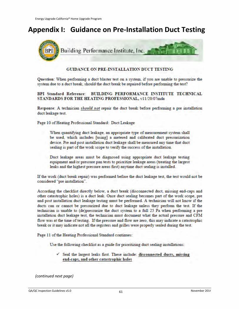
QA/QC Inspection Guidelines v5.0 November 2014
61
Energy Upgrade California® Home Upgrade Program
Appendix I: Guidance on Pre-Installation Duct Testing
(continued next page)

QA/QC Inspection Guidelines v5.0 November 2014
62
Energy Upgrade California® Home Upgrade Program
(Guidance on Pre-Installation Duct Testing – continued)

QA/QC Inspection Guidelines v5.0 November 2014
63
Energy Upgrade California® Home Upgrade Program
Appendix J: Clarification on Blower Door Testing in the
Presence of Asbestos Containing Materials
(continued next page)

QA/QC Inspection Guidelines v5.0 November 2014
64
Energy Upgrade California® Home Upgrade Program
(Clarification on Blower Door Testing in the Presence of Asbestos Materials – continued)

QA/QC Inspection Guidelines v5.0 November 2014
65
Energy Upgrade California® Home Upgrade Program
Appendix K: Guidance on Fireplaces and Blower Door
Testing

QA/QC Inspection Guidelines v5.0 November 2014
66
Energy Upgrade California® Home Upgrade Program
Appendix L: Guidance on Standards Conflicts with Local
Program Rules, Law or Code
(continued next page)

QA/QC Inspection Guidelines v5.0 November 2014
67
Energy Upgrade California® Home Upgrade Program
(Guidance on Standards Conflicts - continued)
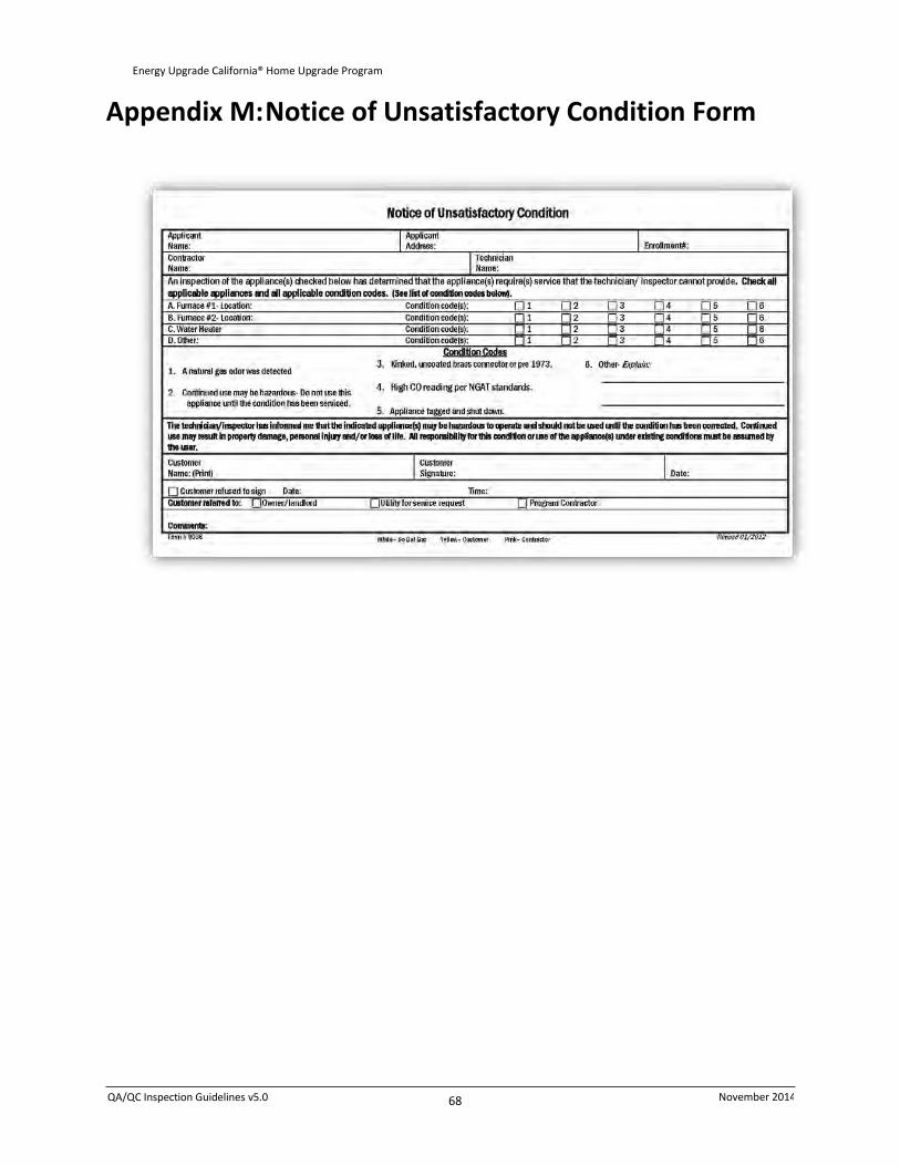
QA/QC Inspection Guidelines v5.0 November 2014
68
Energy Upgrade California® Home Upgrade Program
Appendix M: Notice of Unsatisfactory Condition Form

QA/QC Inspection Guidelines v5.0 November 2014
69
Energy Upgrade California® Home Upgrade Program
Appendix N: C-10 Knob and Tube Wiring Survey Form

QA/QC Inspection Guidelines v5.0 November 2014
70
Energy Upgrade California® Home Upgrade Program
Appendix O: Knob and Tube Caution Sign

QA/QC Inspection Guidelines v5.0 November 2014
71
Energy Upgrade California® Home Upgrade Program
Appendix P: Processing Guidelines
Recommendation, Remediation, Failure Criteria, and Advisory Conditions
A. RESERVATION PHASE PROCESSING:
1. All projects can be processed during the Reservation phase because it is implied that the contractor will remedy the situation during the construction.
2. RHA will inform the customer or contractor of any recommendations or issues found at the project site and any reporting requirements, with the exception of Advisory Table conditions.
3. Recommendation Issues identified at the project site will be included in the Notice of On-Site Pre-Verification Completion e-mail to the customer and contractor.
4. The QC vendor will inform the homeowner to notify SoCalGas® of any natural gas hazardous conditions found at the project site.
B. APPLICATION PHASE PROCESSING:
1. RHA Final QC Report that states “Pass” shall be processed, unless it is under appeal due to a non-safety issue.
2. RHA Final QC Report that states “Pass with Recommendations” shall be processed, unless it is under appeal due to a non-safety issue.
a. Recommendations will be included in the Notice of Incentive Approval to inform the customer and contractor of what RHA has found at the project site or reported in the Desktop Safety Review.
b. An Inspection Safety Letter (ISL) may also be sent to the customer and contractor depending on the recommendation.
3. RHA Final QC Report that states “Pass with Remediation Issues” shall not be processed.
a. Customer and contractor will be notified of the issues found in the field through an ISL.
4. All folders that included an ISL will automatically trigger the RHA Final QC Report to state: “Pass with Recommendations” or “Fail with Remediation Issues”.
C. APPEALS:
5. When a contractor chooses not to Appeal, the project will be processed unless one of the following occurs:
b. The project includes an issue that requires remediation.
c. Mandatory program minimum compliance requirement has not been met.
D. INSPECTION SAFETY LETTERS:
6. If a safety issue is identified in Vision, an ISL will automatically be generated.

QA/QC Inspection Guidelines v5.0 November 2014
72
Energy Upgrade California® Home Upgrade Program
7. If a safety issue is identified in QC Review, the RHA Final QC Report will state: “Pass with Recommendations” or “Pass with Remediation”.
E. ABBREVIATIONS:
8. CAZ: Combustion Appliance Zone
9. CVA: Combustion and Ventilation Air 1
10. CO ppm: Carbon Monoxide parts per million
11. DHW: Domestic Hot Water Heater
12. FAU: Forced Air Unit (Furnace)
13. HPD: Heat Producing Device
F. PASS WITH RECOMMENDATION ISSUES—(Proceed with Payment)
When any condition listed below is present, the contractor must recommend to the homeowner
that the condition(s) be corrected.
14. Mechanical Ventilation is recommended.
15. Exhaust Ventilation (Spot Ventilation) is recommended.
16. Kitchen ambient CO (measured in the center of the kitchen at 6’) exceeds 9 ppm under any of the following conditions:
d. all burners operating,
e. the oven operating, or
f. the broiler operating.
17. Any appliance fails draft and/or spillage under worst case depressurization but passes spillage and draft under natural conditions.
18. Appliance passes Draft and Spillage under worst case and natural conditions and undiluted CO readings are in the ranges shown in Table 1.
TABLE 1
Appliance Type (Appliance Passes Draft/Spillage)
Acceptable CO ppm
Natural Draft FAU
26–275 Gravity Furnace
Floor Furnace
Direct Vent Furnace
Wall Furnace
26–125 Vented Room Heater
Storage Water Heater (Natural Draft)
Tankless Water Heater (Open Combustion)
Oven/Broiler 100–225

QA/QC Inspection Guidelines v5.0 November 2014
73
Energy Upgrade California® Home Upgrade Program
If all appliances in a CAZ pass Draft and Spillage under worst case conditions and the Appliance Ambient
CO ppm exceeds the levels in the Table 2.
TABLE 2
Appliance Type (Appliance Passes WCD Draft/Spillage)
Appliance Ambient CO Exceeds:
Gravity Furnace
2 ppm
Wall Furnace
Floor Furnace
Vented Room Heater
Direct Vent Furnace
Open Combustion Gas Log Fireplace
Insert Sealed Combustion Fireplace
All water heaters in a location that may have a direct effect on the living space2 9 ppm
Gas clothes dryer
19. Single wall vent pipe is used on an existing appliance where double vent pipe is required.3
20. Existing vent pipe terminates below eave. 2
21. Existing vent pipe termination proximity to a window is unacceptable according to Chapter 8 of the California Mechanical Code. 2
22. Misaligned, defective, or multiple draft hoods but appliance vents properly. 2
23. Defective or missing vent cap. 2
24. Light rust in draft hood or heat exchanger.
25. Improper position of thermocouple, pilot generator, pilot or flame.
26. Copper, kinked, corroded, butt-soldered, or pre-1973 flexible gas connector(s) present.
27. Domestic hot water heater burner and burner ignition devices are located less than 18 above the garage floor (not required when unit is Flammable Vapor Ignition Resistant (FVIR) type).
28. Whole house fan vents into attic where a standing pilot open combustion gas appliance is present.
29. Electric clothes dryer located in a living space but does not exhaust outdoors
30. Other.
2 See “Definitions” in the CVA section of the Inspection Guidelines. 3 Does not include appliances/conditions listed in the Advisory Table (Section H).

QA/QC Inspection Guidelines v5.0 November 2014
74
Energy Upgrade California® Home Upgrade Program
G. PASS WITH REMEDIATION ISSUES—(Withhold Payment) Payment is withheld when any condition listed below is present. To qualify for payment,
nonconforming condition(s) must be remediated.
31. A gas leak is detected.
32. Possible asbestos containing material (PACM) is present and no certificate of abatement is provided.
33. Knob and tube wiring is present and the following have not been posted near the primary entrance to the attic, crawlspace, or basement:
g. Notice of Survey by a licensed C-10 Electrical Contractor.
h. Warning Placard (must be present at every entrance).
34. Mechanical Ventilation is required.
35. Worst case depressurization limit has been exceeded in any CAZ (See “Worst Case” Testing Procedures in the Combustion Appliance Safety testing section of the EUC Installation Specifications).
36. Insufficient CVA.
37. Communication between return air and combustion air.
38. Appliance fails draft and/or spillage under natural conditions.
39. Appliance fails draft and/or spillage under worst case conditions (WCC) and undiluted as-measured CO reading exceeds those in Table 3.
TABLE 3
Appliance Type (Appliance Fails WCD Draft/Spillage)
As-Measured CO Exceeds:
Natural Draft FAU
25 ppm
Gravity Furnace
Wall Furnace
Floor Furnace
Vented Room Heater
Direct Vent Furnace
Storage Water Heater (Natural Draft)
Tankless Water Heater (Open Combustion in a location that may have a direct effect on the living space)
1
Open Combustion Gas Log Fireplace

QA/QC Inspection Guidelines v5.0 November 2014
75
Energy Upgrade California® Home Upgrade Program
40. Appliance passes Draft/Spillage under worst case or natural conditions, but the undiluted As-measured CO exceeds those shown in Table 4.
TABLE 4
Appliance Type (Appliance Passes WCD Draft/Spillage)
As-Measured CO Exceeds:
Cooktop/Range Burner (15 above the flame) 25 ppm
Gas Log Fireplace
Oven/Broiler that is not vented properly 100 ppm
Wall Furnace
125 ppm
Vented Room Heater
Storage Water Heater (Natural Draft)
Tankless Water Heater (Open Combustion in a location that may have a direct effect on the living space)
1
Oven/Broiler that is vented properly 225 ppm
Forced Air Furnace (when testing is feasible)
275 ppm Gravity Furnace
Floor Furnace
Direct Vent Furnace
41. FAU Supply Register CO reading exceeds 1 ppm above the ambient CO reading under worst case or natural conditions.
42. Room Ambient CO exceeds 35 ppm.
43. Room Ambient CO exceeds 9 ppm over a 24 hour period.
44. Open combustion FAU or water heater is located in a sleeping area or bathroom.
45. Free-standing unvented gas space heater or a vent free fireplace is in a location that may have a direct effect on the living space.
1
46. Gas clothes dryer located in a living space, but does not exhaust outdoors.
47. Disconnected vent pipe on a combustion appliance that may have a direct effect on the living space.
1
48. A new single wall vent pipe is used where double wall vent pipe is required.
49. Disconnected vent pipe on a combustion appliance in an attached garage or within 4’ of a window/door.
2
50. Improper vent termination. 2
51. Misaligned, defective, or multiple draft hoods causing appliances to not vent properly. 2
52. Excessive rust in draft hood or heat exchanger.
53. Safety switches have been bypassed.
54. Inadequate clearance from combustibles.
55. Flame rollout.

QA/QC Inspection Guidelines v5.0 November 2014
76
Energy Upgrade California® Home Upgrade Program
56. Yellow flame.
57. Delayed ignition.
58. Cracked heat exchanger.
59. HPD (see Item 32.b. below) is in contact with combustible material or insulation.
60. IAQ duct connection requirements have not been met when attic insulation/attic air plane sealing is selected as a retrofit measure:
i. Duct connections, including duct-to-register-boot connections, have not been sealed with UL-181 tape, drawbands, mastic, or other approved duct sealing material.
j. Where ducts are inaccessible, register boot connections have not been sealed inside the boot with UL-181 aluminum tape, mastic, or other approved duct sealing material.
61. Kitchen and bathroom exhaust fan(s) and vent(s) are not continuously connected/ducted to exhaust outdoors.
62. HPD and IAQ photo documentation when requested does not include:
k. Photos of pre-retrofit attic spaces in existing pre-retrofit condition.
l. Photos of all HPDs with barriers/baffles installed with proper clearances to all combustible materials (including insulation) prior to insulation being installed. HPDs include but are not limited to the following:
Recessed light fixtures
Exposed fluorescent fixtures
Doorbell transformers
Fan Motors
Gas vent pipes (including abandoned ones)
Masonry and metal chimneys (including abandoned ones)
Gas and Electric appliances (e.g. water heaters and furnaces).
Any other device that produces heat.
m. Photos of all accessible duct connections including duct-to-register boot connections, showing that they have been sealed with UL-181 tape, draw bands, mastic, or other approved duct sealing material.
n. Where ducts are inaccessible, photos showing that the register boot connections have been sealed from inside the boot with UL-181 aluminum tape, mastic, or other approved duct sealing material.
o. Where ducts are inaccessible, photos showing that the register boot connections have been sealed from inside the boot with UL-181 aluminum tape, mastic, or other approved duct sealing material.
p. Photos showing that kitchen and bathroom exhaust fan(s) and vent(s) are continuously connected and exhaust outdoors.
63. Low-flow showerhead rating less than 1.5 gallons per minute and/or a Thermostatic Control Valve (TCV) was installed when a tankless water heater supplies water to the shower.
64. Other.

QA/QC Inspection Guidelines v5.0 November 2014
77
Energy Upgrade California® Home Upgrade Program
H. FAIL ISSUES (Withhold Payment)
65. The project does not pass the minimum 1 of 3 measures (see items 2 through 5 below) for the program.
66. Fails program Duct Leakage maximum: leakage to outside is greater than 10% of system airflow.
67. Fails program requirement for Building Leakage:
q. Building leakage is greater than 0.35 ACHn,(100% BAS), and a 14% reduction has not been met.
r. Building Leakage is less than 0.245 ACHn (70% BAS), and mechanical ventilation has not been installed.
68. Fails program requirement for Attic Insulation:
s. Attic insulation is less than R-30.
t. Exceptions: Does not apply to (a) inaccessible attics, and (b) attics without sufficient clearance to reach R-30.
69. The heating or cooling system(s) was replaced and the Duct Sealing option was selected, but an additional shell measure that meets program requirements was not completed (Attic Insulation & Air Plane Sealing, Building Leakage, Wall Insulation, Window Replacement, or Floor Insulation)
70. Fails program requirement for Thermostatic Control Valves (TCVs).
u. TCVs have not been installed in all showers.
Exception: Sit-down showers are exempt from TCV requirements.
v. TCV has been installed where hot water is supplied to the shower by a tankless water heater.
I. ADVISORY CONDITIONS Advisory conditions (listed in Table 5 on the next page) are applicable only to existing appliances
that do not directly affect the living space and the installation is not included in the scope of
work. The homeowner must be advised when any such condition is present in the home.
71. Notification to the homeowner of the presence of any gas appliance advisory conditions (see Table 5) is the sole responsibility of the contractor.
72. Any immediate or potential hazard, such as charring from a vent system) or any other identified safety risk must be corrected by the contractor, regardless of whether or not the condition is listed in Table 5.
73. The QC vendor will inform the homeowner only of line item 9 in the Table 5 (NOx Rod Furnace subject to recall) unless any other condition poses an immediate hazard.
w. A Notice of Unsatisfactory Condition must be filled out and signed by the homeowner.
x. A copy will be given to the homeowner, and the file will be uploaded into Vision.

QA/QC Inspection Guidelines v5.0 November 2014
78
Energy Upgrade California® Home Upgrade Program
TABLE 5
Advisory Conditions—Natural Gas Appliances
11. Inoperable Appliance.
12. Insufficient CVA for domestic water heaters installed outside in an enclosure that is not directly connected to the outside wall of the living space (e.g., in a metal shed).
13. Vent pipe (other than Direct Vent) terminations for appliances in outdoor locations:
c. Terminal is not at least 4' below, or 1' above an openable door/window or passive air inlet into the home, or
d. Terminal is less than 4' from a wall and does not extend above the wall and roof.
14. DV (Direct Vent) terminal less than 12' from openable door/window or passive air inlet into the home.
15. Single-wall vent connector extends beyond the ceiling or wall, and no charring is present.
16. Misaligned, missing, or doubled draft hood
17. DHW component(s) missing or damaged4
18. Any clothes dryer exhausting into an appliance enclosure or garage, where lint is not affecting open combustion appliances. (Occupants must be advised to watch for accumulation of dryer lint at draft hood and CVA intake of open combustion appliances in the space.)
19. Horizontal FAU is a NOx Rod Furnace subject to recall.
3 DHW missing or damaged components include: (a) outer combustion chamber cover, (b) inner
rollout shield, (c) T&P valve, (d) any part of the vent system, including the draft hood, and (e) defective gas control (e.g., missing/damaged control knob, thermostat dial)