s-150 mk ii s-75 mk ii, s-100 mk ii, power amplifier · 2019-02-09 · s-75 mk ii, s-100 mk ii,...
TRANSCRIPT

S-75 MK II, S-100 MK II,S-150 MK II
power amplifier
user manual

Musikhaus Thomann
Thomann GmbH
Hans-Thomann-Straße 1
96138 Burgebrach
Germany
Telephone: +49 (0) 9546 9223-0
E-mail: [email protected]
Internet: www.thomann.de
08.02.2019, ID: 141140, 144356, 141141 (V4)
Table of contents
1 General information................................................................................................................................. 41.1 Further information........................................................................................................................... 51.2 Notational conventions.................................................................................................................... 61.3 Symbols and signal words............................................................................................................... 6
2 Safety instructions..................................................................................................................................... 8
3 Features....................................................................................................................................................... 13
4 Connections and controls................................................................................................................... 14
5 Installation and starting up................................................................................................................ 225.1 Tips on handling speakers............................................................................................................ 255.2 Additional useful tips...................................................................................................................... 26
6 Technical specifications....................................................................................................................... 28
7 Plug and connection assignment.................................................................................................... 31
8 Cleaning....................................................................................................................................................... 37
9 Protecting the environment.............................................................................................................. 38
Table of contents
S-75 MK II, S-100 MK II, S-150 MK II
3
1 General information
This user manual contains important information on the safe operation of the device. Read andfollow all safety notes and all instructions. Save this manual for future reference. Make surethat it is available to all persons using this device. If you sell the device to another user, be surethat they also receive this manual.
Our products and user manuals are subject to a process of continuous development. We there‐fore reserve the right to make changes without notice. Please refer to the latest version of theuser manual which is ready for download under www.thomann.de.
General information
power amplifier
4

1.1 Further information
On our website (www.thomann.de) you will find lots of further information and details on thefollowing points:
Download This manual is also available as PDF file for you to download.
Keyword search Use the search function in the electronic version to find the topics ofinterest for you quickly.
Online guides Our online guides provide detailed information on technical basicsand terms.
Personal consultation For personal consultation please contact our technical hotline.
Service If you have any problems with the device the customer service willgladly assist you.
General information
S-75 MK II, S-100 MK II, S-150 MK II
5
1.2 Notational conventions
This manual uses the following notational conventions:
The letterings for connectors and controls are marked by square brackets and italics.
Examples: [VOLUME] control, [Mono] button.
References to other locations in this manual are identified by an arrow and the specified pagenumber. In the electronic version of the manual, you can click the cross-reference to jump tothe specified location.
Example: See Ä ‘Cross-references’ on page 6.
1.3 Symbols and signal words
In this section you will find an overview of the meaning of symbols and signal words that areused in this manual.
Letterings
Cross-references
General information
power amplifier
6

Signal word Meaning
DANGER! This combination of symbol and signal word indicates animmediate dangerous situation that will result in death orserious injury if it is not avoided.
CAUTION! This combination of symbol and signal word indicates a pos‐sible dangerous situation that can result in minor injury if itis not avoided.
NOTICE! This combination of symbol and signal word indicates a pos‐sible dangerous situation that can result in material andenvironmental damage if it is not avoided.
Warning signs Type of danger
Warning – high-voltage.
Warning – danger zone.
General information
S-75 MK II, S-100 MK II, S-150 MK II
7

2 Safety instructions
This device amplifies electric audio frequency signals to operate passive speakers. Use thedevice only as described in this user manual. Any other use or use under other operating con‐ditions is considered to be improper and may result in personal injury or property damage. Noliability will be assumed for damages resulting from improper use.
This device may be used only by persons with sufficient physical, sensorial, and intellectualabilities and having corresponding knowledge and experience. Other persons may use thisdevice only if they are supervised or instructed by a person who is responsible for their safety.
DANGER!Danger for childrenEnsure that plastic bags, packaging, etc. are disposed of properly and are notwithin reach of babies and young children. Choking hazard!
Ensure that children do not detach any small parts (e.g. knobs or the like) fromthe unit. They could swallow the pieces and choke!
Never let children unattended use electrical devices.
Intended use
Safety
Safety instructions
power amplifier
8

DANGER!Electric shock caused by high voltages insideWithin the device there are areas where high voltages may be present. Neverremove any covers.
There are no user-serviceable parts inside.
Do not use the device if covers, protectors or optical components are missing ordamaged.
DANGER!Electric shock caused by short-circuitAlways use proper ready-made insulated mains cabling (power cord) with a pro‐tective contact plug. Do not modify the mains cable or the plug. Failure to do socould result in electric shock/death or fire. If in doubt, seek advice from a regis‐tered electrician.
Safety instructions
S-75 MK II, S-100 MK II, S-150 MK II
9

CAUTION!Possible hearing damageWith loudspeakers or headphones connected, the device can produce volumelevels that may cause temporary or permanent hearing impairment.
Do not operate the device permanently at a high volume level. Decrease thevolume level immediately if you experience ringing in your ears or hearingimpairment.
NOTICE!Risk of fireDo not block areas of ventilation. Do not install the device near any direct heatsource. Keep the device away from naked flames.
Safety instructions
power amplifier
10

NOTICE!Operating conditionsThis device has been designed for indoor use only. To prevent damage, neverexpose the device to any liquid or moisture. Avoid direct sunlight, heavy dirt, andstrong vibrations.
Only operate the device within the ambient conditions specified in the chapter‘Technical specifications’ of this user manual. Avoid heavy temperature fluctua‐tions and do not switch the device on immediately after it was exposed to tem‐perature fluctuations (for example after transport at low outside temperatures).
Dust and dirt inside can damage the unit. When operated in harmful ambientconditions (dust, smoke, nicotine, fog, etc.), the unit should be maintained byqualified service personnel at regular intervals to prevent overheating and othermalfunction.
Safety instructions
S-75 MK II, S-100 MK II, S-150 MK II
11

NOTICE!Power supplyBefore connecting the device, ensure that the input voltage (AC outlet) matchesthe voltage rating of the device and that the AC outlet is protected by a residualcurrent circuit breaker. Failure to do so could result in damage to the device andpossibly injure the user.
Unplug the device before electrical storms occur and when it is unused for longperiods of time to reduce the risk of electric shock or fire.
NOTICE!Magnetic fieldsThe device generates strong magnetic fields that can interfere with the functionof poorly shielded devices. The strongest magnetic fields are directly above andbelow the power amplifier. Therefore, never place sensitive devices such as pre-amplifiers, radio transmission systems, or tape decks directly above or below thepower amplifier. When installing the power amplifier into a rack, you should placeit in the lowest position, and further equipment such as pre-amplifiers in thehighest position.
Safety instructions
power amplifier
12

3 Features
n Output power 2 × 45 W to 250 W (depending on the model)n Speaker Twist and terminal connections for speakersn All protection circuits incl. soft startn Input level switchable from –0 to +4 dbn Fanless operationn Standby function
Features
S-75 MK II, S-100 MK II, S-150 MK II
13
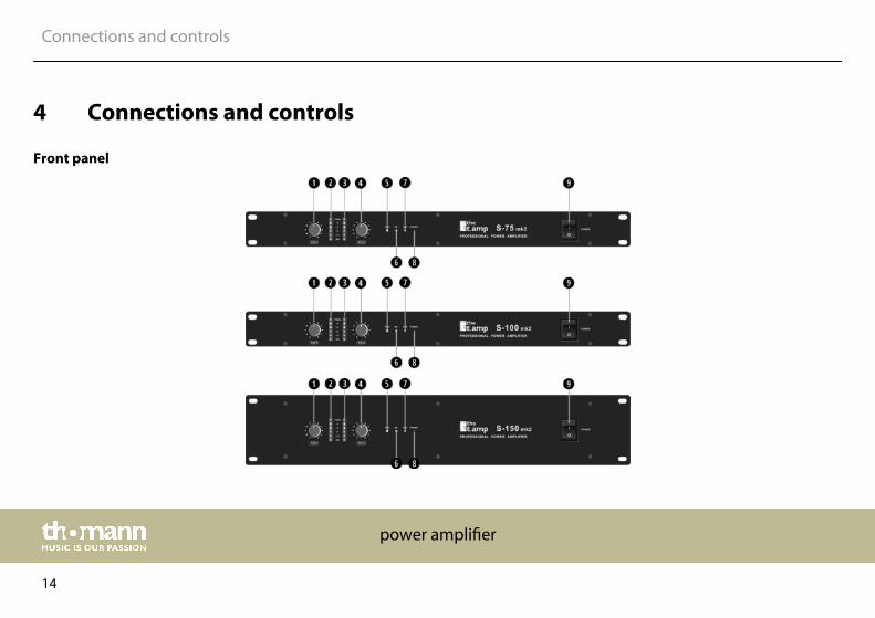
4 Connections and controls
Front panel
Connections and controls
power amplifier
14

1 CH-1: Input level controller for channel 1
Use the input level controllers CH-1 and CH-2 (4) on the front panel to control thesignal amplification in the respective channel. If possible, turn this control fully tothe right stop (= 0 dB attenuation) for optimal headroom. Professional poweramplifiers then output their rated power, if the input voltage is 0.775 V resp. 1.4 V(depending on the position of the switch for the input sensitivity [19]).
2/3 PEAK: Indicator for signal and maximum level
These LED chains indicate the output power of the device in the respectivechannel. The PEAK indicator lights up when the output power reaches its max‐imum. If this indicator lights up continuously, the volume of the respective channelmust be reduced. To do so, turn to the input level knob counter-clockwise.
4 CH-2: Input level controller for channel 2
Input level controller for channel 2, functionality is equal to point (1) .
Connections and controls
S-75 MK II, S-100 MK II, S-150 MK II
15

5 PRO: Indicator for activated protection circuit
This indicator lights up, if one of the following situations arises in one of the chan‐nels:
• 3-5 seconds after switching on, as the speakers are still electrically disconnectedfrom the power amp.
• The temperature of the output transistors exceeds 85°C.
• A malfunction exists in the device.
6 BR: Indicator for mono operation in bridged mode
Please read more about the available operating modes in chapter .
7 PAR: Indicator for mono operation in parallel mode
Please read more about the available operating modes in chapter .
Connections and controls
power amplifier
16

8 POWER: Power indicator light
Lights up green when the unit is turned on. In standby mode, the LED lights red.When the unit receives a signal again, it switches back to normal mode and the LEDlights green again.
9 POWER: On / off switch (9)
This switch turns the power on and off. When switching on the protection circuitsare activated. After a few seconds you will hear two "clicks" - now the speakers areelectrically connected to the amplifier and the device is ready to operate.
When switching on electronic devices, especially power amps, the power con‐sumption is particularly high. Make sure you don't turn on too many devices simul‐taneously. Otherwise, the power supply circuit may be overloaded and the RCD willdisconnect the power supply.
Connections and controls
S-75 MK II, S-100 MK II, S-150 MK II
17
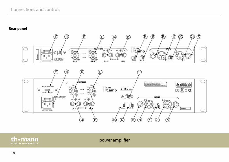
Rear panel
Connections and controls
power amplifier
18

10 Mains connector with fuse holder
Connect the supplied power cord here and supply the device with mains voltage.
11 ERP ON | OFF
This switch enables/disables the standby feature. If enabled, the unit automaticallyenters the standby mode when no input signal is present for at least fifteenminutes.
12/13 Speaker outputs CH-1/2
Connect speakers to the speaker outputs of channel 1 and 2 using SPK cables(wiring = 1+ 2+ 1– 2–).
14/15 Speaker terminals CH-1/2
You can connect the speakers either with cable lugs or bare wire to the cable termi‐nals on the rear panel.
Connections and controls
S-75 MK II, S-100 MK II, S-150 MK II
19

16 GROUND/LIFT switch
In normal operation signal source and power amplifier should share the sameground potential. In some constellations this admittedly leads to ground loops andthus to humming. If this happens vary the toggle switch setting for ground poten‐tial on the rear panel of the unit. This switch connects in one setting the shield/ground of the input signal with the housing of the power amp and thus with mainsearthing. In the other setting there is no electrical connection between the shield/ground of the input signal and the power amp housing.
17 STE / PAR / BR
Use this switch to select the operating mode of the power amp: stereo (STE), par‐allel (PAR) or bridged (BR).
18 CH-2
Connect the line-level signals to be amplified to the 1/4" balanced TRS phone jackinput of Channel 2 using a 1/4" phone jack cable.
19 CH-2
Connect the line-level signals to be amplified to the XLR input of Channel 2 using aXLR cable.
Connections and controls
power amplifier
20

20 0.77V | 1.4V | 26dB
The input level at which the power amplifier delivers its rated output power can beswitched between 0,775 VRMS and 1,4 VRMS. Often multiple amplifiers are usedsimultaneously. In this case, switch to the "26 dB" position, the signal will then beamplified by all amps equally. Thus, you can combine different power amps of theS-series, and always get the same output level.
21 CH-1 (MONO)
Connect the line-level signals to be amplified to the XLR input of Channel 1 using aXLR cable.
22 CH-1 (MONO)
Connect the line-level signals to be amplified to the 1/4" balanced TRS phone jackinput of Channel 1 using a 1/4" phone jack cable.
23 Switch for power supply voltage
Before connecting the amplifier to the mains power supply, ensure that the mainsvoltage switch on the bottom side (or rear side for S-150) is in the position that cor‐responds to the actual power available (in Germany AC 230 V). If in doubt, consultan electrician.
Connections and controls
S-75 MK II, S-100 MK II, S-150 MK II
21

5 Installation and starting up
Unpack and check carefully there is no transportation damage before using the unit. Keep theequipment packaging. To fully protect the product against vibration, dust and moisture duringtransportation or storage use the original packaging or your own packaging material suitablefor transport or storage, respectively.
Create all connections while the device is off. Use the shortest possible high-quality cables forall connections. Take care when running the cables to prevent tripping hazards.
Installation and starting up
power amplifier
22

DANGER!Electric shock caused by high voltages at the power amplifier outputThe output voltages of modern high-performance amplifiers may result in deathor serious injury.
Never touch the bare ends of loudspeaker cables when the amplifier is on.
NOTICE!Magnetic fieldsThe device generates strong magnetic fields that can interfere with the functionof poorly shielded devices. The strongest magnetic fields are directly above andbelow the power amplifier. Therefore, never place sensitive devices such as pre-amplifiers, radio transmission systems, or tape decks directly above or below thepower amplifier. When installing the power amplifier into a rack, you should placeit in the lowest position, and further equipment such as pre-amplifiers in thehighest position.
Model types S-75 and S-100
Installation and starting up
S-75 MK II, S-100 MK II, S-150 MK II
23

The unit has been designed for rack mounting in a standard 19-inch rack; it occupies one rackunit.
Model type S-150
The device has been designed for rack mounting in a standard 19-inch rack; it occupies tworack units.
Rack mounting
Rack mounting
Installation and starting up
power amplifier
24

5.1 Tips on handling speakers
We recommend you to set up the speakers in a way, that the sound signals can reach the audi‐ence unobstructedly. It will often be helpful to mount the speakers on tripods. Thus, the soundwill be evenly spread with maximum range throughout the audience area.
Always use high grade cable to connect your equipment. Otherwise you won't reach max‐imum sound quality.
For optimum results both impedance and power handling of the speakers must match therequirements of the amplifier. Always follow the technical specifications of the speakers! Theoverall impedance of the connected loudspeakers must not deceed the minimum outputimpedance of the amp. The amps max. RMS output power should be 50 % above the powerhandling capacity of the connected speakers.
If you notice distortion during operation, either the amp or the speaker is overloaded. This maypermanently damage the amp or the speaker. Always reduce the volume when you hear dis‐tortion.
Installation and starting up
S-75 MK II, S-100 MK II, S-150 MK II
25

5.2 Additional useful tips
Depending on the individual application, the amplifier can be used in different operationmodes:
Stereo mode
The two amplifier channels operate independently ofone another, either channel (CH1 and CH2) is amplifiedand connected to loudspeakers, the volume can be con‐trolled separately for the two outputs.
Parallel mode
The two amplifier channels receive the same inputsignal from channel CH1 and loudspeakers are con‐nected to each amplifier, the volume for both outputs iscontrolled by the volume control of CH1.
Bridged mode
Possible operation modes
Installation and starting up
power amplifier
26

The two amplifier channels are internally connected insuch a way that twice the output power is available.Only the input signal from channel CH1 is amplified andloudspeakers are connected only to the correspondinglymarked output. The volume is controlled by the volumecontrol of CH1.
For each output of the amplifier, the total impedance resulting from the loudspeakers con‐nected to it must not be below the allowed minimal impedance of the amplifier output. Con‐necting more than one loudspeaker to an amplifier output, please consider:
n If the loudspeakers are connected in a series, the individual impedances will be added up.n If the loudspeakers are connected in parallel, the reciprocal of the total impedance equals
the sum of the reciprocals of the individual impedances.
Example: Using two loudspeakers which have the same impedance, the impedance doubles ifthey are connected in a series, but it halves if they are connected in parallel.
For detailed information related to this topic please refer to our Online Guide "PA Speakers’"(www.thomann.de).
Installation and starting up
S-75 MK II, S-100 MK II, S-150 MK II
27

6 Technical specifications
Model type S-75 S-100 S-150
Amplifier class AB AB AB
Input impedance 20 kΩ (active, balanced)
Input level 21 dBV / 9 V
Output power RMS8 Ω, stereo 2 × 45 W 2 × 65 W 2 × 85 W
RMS 4 Ω, stereo 2 × 75 W 2 × 100 W 2 × 150 W
RMS 8 Ω, bridged 150 W 200 W 250 W
Frequency response 10 Hz … 50 kHz, –1.5 dB
Signal-to-noise ratio, A-weighted, RMS > 80 dB > 80 dB > 85 dB
Damping factor (1 kHz, 8 Ω) > 150 dB
Sensitivity 0.77 V … 1.4 V (26 dB)
Slew rate 35 V/µs 35 V/µs 40 V/µs
Technical specifications
power amplifier
28

Model type S-75 S-100 S-150
Crosstalk @ rated power (1 kHz, 8 Ω) > 70 dB
Power consumption 1/2 nominal power
8 Ω
Typical current consumption depending on the output power level(ARMS). All values based on a 230 V mains voltage and a 1 kHz inputsignal at 0 dB (sine).
65 W 100 W 120 W
Supply voltage 115 – 230 V 50/60 Hz
Protective circuits Short-circuit current limitation, DC voltage fault, fuse for supply voltage,limiter, temperature, mains transients
Installation 19", 1 RU 19", 1 RU 19", 2 RU
Dimensions (W × H × D) 483 × 330 × 44 483 × 330 × 44 483 × 320 × 88
Weight 7.5 kg 7.5 kg 11.5‑kg
Ambient conditions Temperature range 0 °C…40 °C
Relative humidity 50 %, non condensing
Technical specifications
S-75 MK II, S-100 MK II, S-150 MK II
29

Model type S-75 S-100 S-150
Power 4 Ω / channel 75 W 100 W 150 W
Channels 2 2 2
2 Ω stable No No No
DSP / frequency No No No
Convection cooling Yes Yes Yes
Further information
Technical specifications
power amplifier
30

7 Plug and connection assignment
This chapter will help you select the right cables and plugs to connect your valuable equip‐ment in such a way that a perfect sound experience is ensured.
Please note these advices, because especially in ‘Sound & Light’ caution is indicated: Even if aplug fits into the socket, an incorrect connection may result in a destroyed power amp, a shortcircuit or ‘just’ in poor transmission quality!
Unbalanced transmission is mainly used in semi-professional environment and in hifi use.Instrument cables with two conductors (one core plus shielding) are typical representatives ofthe unbalanced transmission. One conductor is ground and shielding while the signal is trans‐mitted through the core.
Unbalanced transmission is susceptible to electromagnetic interference, especially at lowlevels, such as microphone signals and when using long cables.
In a professional environment, therefore, the balanced transmission is preferred, because thisenables an undisturbed transmission of signals over long distances. In addition to the conduc‐tors ‘Ground’ and ‘Signal’, in a balanced transmission a second core is added. This also transfersthe signal, but phase-shifted by 180°.
Introduction
Balanced and unbalanced trans‐mission
Plug and connection assignment
S-75 MK II, S-100 MK II, S-150 MK II
31
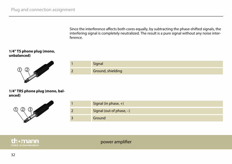
Since the interference affects both cores equally, by subtracting the phase-shifted signals, theinterfering signal is completely neutralized. The result is a pure signal without any noise inter‐ference.
1 Signal
2 Ground, shielding
1 Signal (in phase, +)
2 Signal (out of phase, –)
3 Ground
1/4" TS phone plug (mono,unbalanced)
1/4" TRS phone plug (mono, bal‐anced)
Plug and connection assignment
power amplifier
32
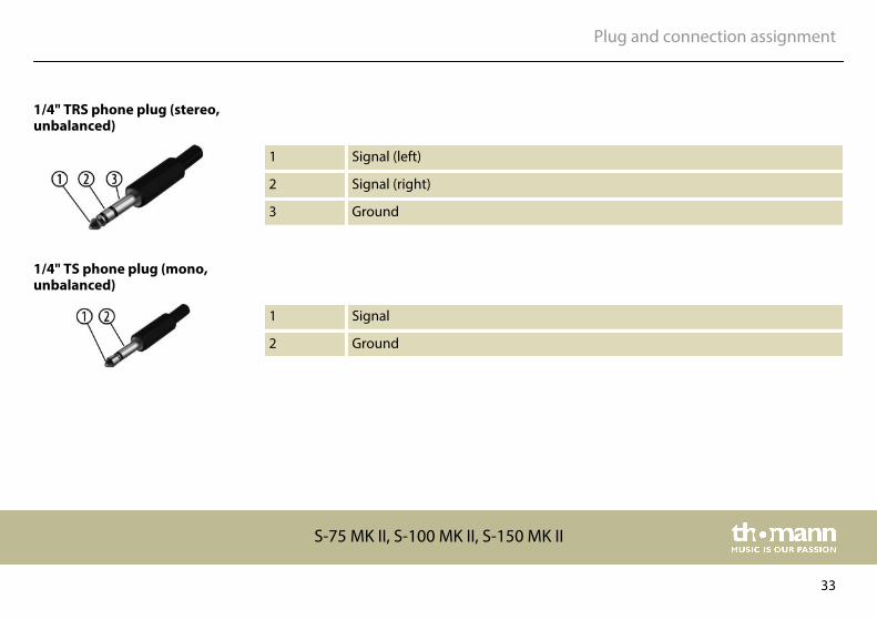
1 Signal (left)
2 Signal (right)
3 Ground
1 Signal
2 Ground
1/4" TRS phone plug (stereo,unbalanced)
1/4" TS phone plug (mono,unbalanced)
Plug and connection assignment
S-75 MK II, S-100 MK II, S-150 MK II
33

1 Signal (in phase, +)
2 Signal (out of phase, –)
3 Ground
1 Signal (left)
2 Signal (right)
3 Ground, shielding
3.5 mm TRS phone plug (mono,balanced)
Three-pole 1/8" mini phone jack(stereo, unbalanced)
Plug and connection assignment
power amplifier
34

1 Ground, shielding
2 Signal (in phase, +)
3 Signal (out of phase, –)
4 Shielding on plug housing (option)
1 Ground, shielding
2 Signal
3 Bridged to pin 1
XLR plug (balanced)
XLR plug (unbalanced)
Plug and connection assignment
S-75 MK II, S-100 MK II, S-150 MK II
35
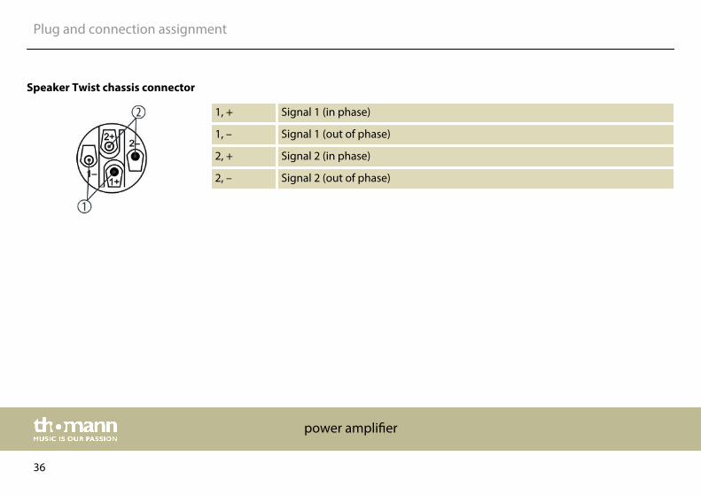
1, + Signal 1 (in phase)
1, – Signal 1 (out of phase)
2, + Signal 2 (in phase)
2, – Signal 2 (out of phase)
Speaker Twist chassis connector
Plug and connection assignment
power amplifier
36

8 Cleaning
The fan grids of the device must be cleaned of any contamination, such as dust, etc. on a reg‐ular basis. Before cleaning, switch off the device and disconnect mains-operated devices fromthe mains. Only use pH-neutral, solvent-free and non-abrasive cleaning agents. Clean the unitwith a slightly damp lint-free cloth.
Fan grids
Cleaning
S-75 MK II, S-100 MK II, S-150 MK II
37
9 Protecting the environment
For the transport and protective packaging, environmentally friendly materials have beenchosen that can be supplied to normal recycling.
Ensure that plastic bags, packaging, etc. are properly disposed of.
Do not just dispose of these materials with your normal household waste, but make sure thatthey are collected for recycling. Please follow the notes and markings on the packaging.
This product is subject to the European Waste Electrical and Electronic Equipment Directive(WEEE) in its currently valid version. Do not dispose with your normal household waste.
Dispose of this device through an approved waste disposal firm or through your local wastefacility. When discarding the device, comply with the rules and regulations that apply in yourcountry. If in doubt, consult your local waste disposal facility.
Disposal of the packaging mate‐rial
Disposal of your old device
Protecting the environment
power amplifier
38


Musikhaus Thomann · Hans-Thomann-Straße 1 · 96138 Burgebrach · Germany · www.thomann.de