rz-x700f series - sharp direct australia, home …€¦ · model rz-x700f series modell modele...
TRANSCRIPT

POS TERMINALKASSENTERMINALTERMINAL DE POINT DE VENTETERMINAL POS
HARDWARE OPERATION MANUALTECHNISCHE BEDIENUNGSANLEITUNG
MANUEL D'UTILISATIONMANUAL TECNICO
RZ-X700F SeriesMODELMODELLMODELEMODELO


1
INTRODUCTION
IMPORTANT
Thank you very much for the purchase of a SHARP POS Terminal.
Please read this manual carefully before operating your POS Terminal.
Please keep this manual for future reference.
• Install this terminal in a location that is not subjected to direct radiation, unusual temperature changes, and high humidity or exposure to water or other liquids. Installation in such locations could cause damage to the cabinet and the electronic components.
• Do not drop this terminal nor subject it to any strong shock.This may cause damage to the terminal and the hard disk mounted in it.
•Do not apply excessive pressure to the display. Do not use a sharp-pointed object on the display. This may cause damage to the LCD display.
•The socket-outlet shall be installed near the equipment and shall be easily accessible.For a complete electrical disconnection, remove the AC plug from the wall outlet.
•The terminal plugs into any standard wall outlet (official / nominal voltage).Other electrical devices on the same electrical circuit could cause the terminal to malfunction.
•Slots and openings in the cabinet and the back have been provided for ventilation. To ensure the reliable operation of your system and protect it from overheating, these openings must not be blocked or covered.
• Please observe the following when an optional drawer is used. The drawer units should be securely fitted to the supporting platform to avoid instability when the drawers are open.
Engl
ish

2
• Please shut down the terminal and disconnect it from the AC supply before connecting or disconnecting external devices to the COM ports.
IMPORTANT
The wires in this mains lead are coloured in accordance with the following code:
As the colours of the wires in the mains lead of this apparatus may not correspond with the coloured markings identifying the terminals in your plug, proceed as follows.
The wire which is coloured GREEN-AND-YELLOW must be connected to the terminal in the plug which is marked by the letter E or by the safety earth symbol or coloured green or green-and-yellow.
The wire which is coloured BLUE must be connected to the terminal which is marked with the letter N or coloured black.
The wire which is coloured BROWN must be connected to the terminal which is marked with the letter L or coloured red.
Ensure that your equipment is connected correctly - if you are in any doubt, consult a qualified electrician.
"WARNING: THIS APPARATUS MUST BE EARTHED."
Noise level: 37,3 dB(A) Measured according to EN ISO 7779:2001
[Maximum value if the optional cash drawer springs open: 74,1 dB(A)]
GREEN-AND-YELLOW: Earth
BLUE: Neutral
BROWN: Live
Note:• DefaultvoltageatPin9ofCOM2/COM3is5V.
FOR CUSTOMERS IN U.K.

3
TABLE OF CONTENTS
SYSTEM OVERVIEW 4
DISPLAY 7
BEFORE CALLING FOR SERVICE 8
LIST OF OPTIONS 8
SPECIFICATIONS 9
Copyright•ThecopyrightofthismanualbelongstoSHARPCorporation.
•Thismanualmaynotbereproducedinwholeorinpartwithoutthepriorexplicit permission of SHARP Corporation.
Trademarks•IntelistheregisteredtrademarkofIntelCorporation.
•MicrosoftandWindowsareregisteredtrademarksofMicrosoftCorporation.
•Allothertrademarksarethepropertyoftherespectivecompany.

4
SYSTEM OVERVIEW
Front view
Operation Display (Touch Panel) 15 inch TFT-LCD screen with touch sensitive screen. Displays the operational status of the system and the system can be operated by touch screen.
1
Power Button After the terminal has been connected to the AC power supply push the power button to turn on the terminal.
2
HDD Indicator LED lights up when the hard disk drive is reading data from or writing data to the drive.
3
Power Indicator LED lights up when the system is on.
4
2
1
43 5
6
5
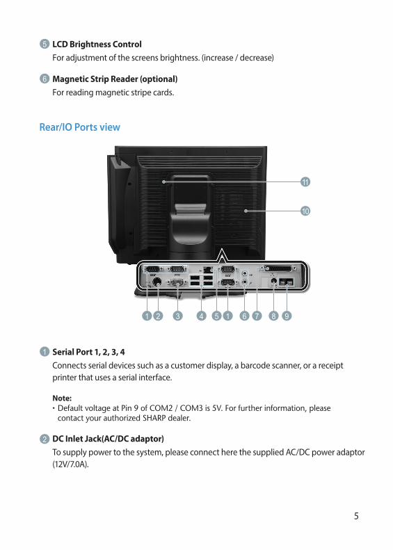
LCD Brightness ControlFor adjustment of the screens brightness. (increase / decrease)
5
Magnetic Strip Reader (optional)For reading magnetic stripe cards.
6
Rear/IO Ports view
Serial Port 1, 2, 3, 4Connects serial devices such as a customer display, a barcode scanner, or a receipt printer that uses a serial interface.
1
Note:• DefaultvoltageatPin9ofCOM2/COM3is5V.Forfurtherinformation,pleasecontactyourauthorizedSHARPdealer.
2 3 4 1 6 981
10
11
5 7
DC Inlet Jack(AC/DC adaptor)To supply power to the system, please connect here the supplied AC/DC power adaptor (12V/7.0A).
2
6
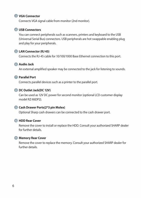
USB Connectors You can connect peripherals such as scanners, printers and keyboard to the USB (Universal Serial Bus) connectors. USB peripherals are hot swappable enabling plug and play for your peripherals.
4
LAN Connector (RJ 45) Connects the RJ-45 cable for 10/100/1000 Base Ethernet connection to this port.
5
Audio Jack An external amplified speaker may be connected to the jack for listening to sounds.
6
7 Parallel Port Connects parallel devices such as a printer to the parallel port.
DC Outlet Jack(DC 12V)Can be used as 12V DC power for second monitor (optional LCD customer display model RZ-X6DP2).
8
9 Cash Drawer Ports(2*3 pin Molex) Optional Sharp cash drawers can be connected to the cash drawer port.
10 HDD Rear Cover Remove the cover to install or replace the HDD. Consult your authorized SHARP dealer for further details.
11 Memory Rear Cover Remove the cover to replace the memory. Consult your authorized SHARP dealer for further details.
VGA ConnectorConnects VGA signal cable from monitor (2nd monitor).
3

7
DISPLAY
Display angle
The display may be tilted for the best viewing angle. The angle can be adjusted within 140 degrees left/right and 45 degrees up/down as illustrated in the picture.
Caution:• Donotpullthedisplaybeyondthemaximumtiltanglenorapplyexcessivepressuretothedisplay.
• Makesuretoholdthebodywhenpullingthedisplaysothattheterminalmaynotmove.
• TheLCDmodulebuiltinthisPOSterminalismanufacturedwithhighlyprecisetechnology,howeverbrightpixelsorblankpixelsmayappear.Alsoanirregularcolorandbrightnessmayoccurdependingontheviewangle.PleasenotethatthistypeofphenomenaiscommonforLCDsandmaynotbeamalfunction.
• Thebacklightinthedisplayisaconsumablepart.• WhentheLCDdisplaycannolongerbeadjustedandbecomesdarker,youshouldreplacetheLCDmodule.ConsultyourauthorizedSHARPdealerforfurtherdetails.

8
BEFORE CALLING FOR SERVICEThe condition shown in the below left-hand column does not necessarily indicate functional faults of the terminal. Please check the listed items at the right-hand column “Checking” before calling for service.
The following options are available for your POS terminal: Do not try to install options yourself.
For details, contact your authorized SHARP dealer.
Condition Checking
The power indicator is not lit.
•IsACpoweravailableattheelectricaloutlet?
•IstheACplugoftheAC/DCadapterconnectedtotheelectricaloutlet?
•IstheACpowercorddisconnectedorlooselyconnectedtotheAC/DCAdapter?
•IstheACadaptersDCpowercableconnected to the DC inlet Jack of the POS terminal?
•Isthepowerswitchoftheterminalturned“ON”?
LIST OF OPTIONS
1. Magnetic card reader model RZ-X6MR1
2. 2 line rear customer display model RZ-X6DP1
3. LCD customer display model RZ-X6DP2
4. Remote drawer models ER-03DW/04DW/05DW/03DWB4/05DWB5
5. The ER-48CC3 till is used for the ER-03DW/03DWB4
6. The ER-48CC2 till is used for the ER-04DW
7. The ER-58CC till is used for the ER-05DW/05DWB5

9
SPECIFICATIONS
Model RZ-X700F series
External Dimensions 365(W) × 234(D) × 360(H) mm
Weight- RZ-X745F: 6.46 kg- RZ-X730F: 6.58 kg
Power source Official / nominal voltage and frequency
Power consumption Operating: less than 84W
Working temperature 5 to 35 °C
CPU Intel Atom D525 dual core @ 1.8GHz
Hard Disk 320GB 2.5inch SATA version 2.0
Memory SO-DIMM(204pin) DDR3 2GB up to 4GB
Display
Type: TFT Color LCD with backlight Analog touch panel
Size: 381 mm (15inch) full screenResolution: 1024 × 768 dotsControl: XGA
AC / DC Adapter 84W(12V/7.0A)
Accessories AC-Adaptor, AC Cable and Cable Cover
*Specificationsandappearancesubjecttochangewithoutnoticeforimprovement.

10
11
EINLEITUNG
WICHTIG
Wir danken Ihnen, daß Sie sich für den Erwerb des Sharp Kassenterminals entschieden haben.
Bitte lesen Sie diese Bedienungsanleitung vor Inbetriebnahme des Kassenterminals sorgfältig durch.
Diese Bedienungsanleitung sollte sorgfältig aufbewahrt werden, damit sie in Zukunft jederzeit griffbereit ist.
• Als Aufstellplatz Ihres Kassenterminals sollte keine Stelle gewählt werden in der die Kasse, direkter Sonneneinstrahlung, ungewöhnlichen Temperaturschwankungen, hoher Luftfeuchtigkeit oder der Beeinflussung durch Wasser bzw. andere Flüssigkeiten, ausgesetzt wird. Das Aufstellen des Kassenterminals an solchen Plätzen könnte zu Beschädigungen des Gehäuses oder der elektrischen Bauteile führen.
• Das Kassenterminal nicht fallen lassen, es keinen starken Erschütterungen aussetzen und nicht dagegen schlagen. Dies kann das Kassenterminal und die eingebaute Festplatte beschädigen.
• Keinen übermäßigen Druck auf das Display ausüben. Keine scharfkantigen Objekte auf dem Display benutzen. Übermäßiger Druck kann das LCD-Display beschädigen.
• Die Netzsteckdose muss nahe dem Gerät angebracht und leicht zugänglich sein. Zur vollständigen Trennung vom elektrischen Strom den Netzstecker ziehen.
• Das Kassenterminal kann an jede normale Steckdose (offizielle, nominale Netzspannung) angeschlossen werden. Beim Anschluss von anderen Elektrogeräten an den gleichen Stromkreis kann es zu Störungen des Kassenterminals kommen.
Deu
tsch

12
• Einschübe und Öffnungen im Gehäuse und auf der Rückseite sind für Ventilation vorgesehen. Um eine sichere Bedienung ihres Systems zu gewährleisten und es vor Überhitzung zu schützen dürfen diese Öffnungen nicht blockiert oder abgedeckt werden.
• Bitte bei Verwendung einer optionalen Schublade folgendes beachten: Die Schubladen sollte so auf der Aufstellfläche angebracht sein, dass das Öffnen der Schublade zu keiner Instabilität führt.
• Bitte das Terminal runterfahren und von der Haupt-Stromversorgung trennen, bevor externe Geräte an den COM Ports angeschlossen oder von diesen entfernt werden. Hinweis: Standardmäßig liegen an Pin 9 von COM2 / COM3 5V.
Geräuschpegel: 37,3 dB(A) Gemessen nach EN ISO 7779:2001
[Spitzenwert bei Aufspringen der optionalen Kassenschublade: 74,1 dB(A)]

13
INHALT
SYSTEM EIGENSCHAFTEN 14 BEDIENER ANZEIGE 17
BEVOR SIE DEN KUNDENDIENSTTECHNIKER ANFORDERN 18
SONDERZUBEHÖR 18
TECHNISCHE DATEN 19
Copyright• Das Copyright dieser Anleitung bezieht sich auf SHARP Corporation.
• Das Kopieren oder anderweitige auch teilweise Reproduktionen sind ohne vorherige schriftliche Genehmigung der SHARP Corporation ausdrücklich verboten.
Trademarks• Intel ist ein eingetragenes Warenzeichen der Intel Corporation.
• Microsoft und Windows sind eingetragene Warenzeichen der Microsoft Corporation.
• Alle weiteren Warenzeichen sind das Eigentum des jeweiligen Unternehmen.
14
SYSTEM EIGENSCHAFTEN
Vorderansicht
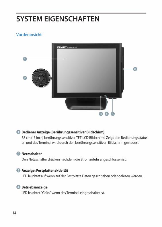
Bediener Anzeige (Berührungssensitiver Bildschirm)38 cm (15 inch) berührungssensitiver TFT-LCD Bildschirm. Zeigt den Bedienungsstatus an und das Terminal wird durch den berührungssensitiven Bildschirm gesteuert.
1
NetzschalterDen Netzschalter drücken nachdem die Stromzufuhr angeschlossen ist.
2
Anzeige: FestplattenaktivitätLED leuchtet auf wenn auf der Festplatte Daten geschrieben oder gelesen werden.
3
BetriebsanzeigeLED leuchtet “Grün” wenn das Terminal eingeschaltet ist.
4
2
1
43 5
6
15
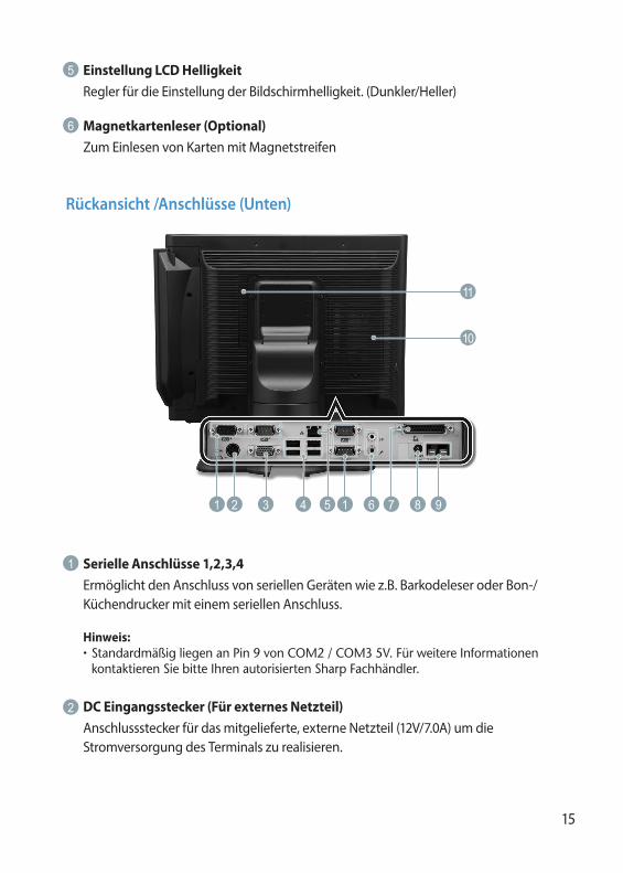
Einstellung LCD HelligkeitRegler für die Einstellung der Bildschirmhelligkeit. (Dunkler/Heller)
5
Magnetkartenleser (Optional)Zum Einlesen von Karten mit Magnetstreifen
6
Rückansicht /Anschlüsse (Unten)
Serielle Anschlüsse 1,2,3,4Ermöglicht den Anschluss von seriellen Geräten wie z.B. Barkodeleser oder Bon-/Küchendrucker mit einem seriellen Anschluss.
1
Hinweis:• StandardmäßigliegenanPin9vonCOM2/COM35V.FürweitereInformationenkontaktierenSiebitteIhrenautorisiertenSharpFachhändler.
DC Eingangsstecker (Für externes Netzteil)Anschlussstecker für das mitgelieferte, externe Netzteil (12V/7.0A) um die Stromversorgung des Terminals zu realisieren.
2
2 3 4 1 6 981
10
11
5 7
16
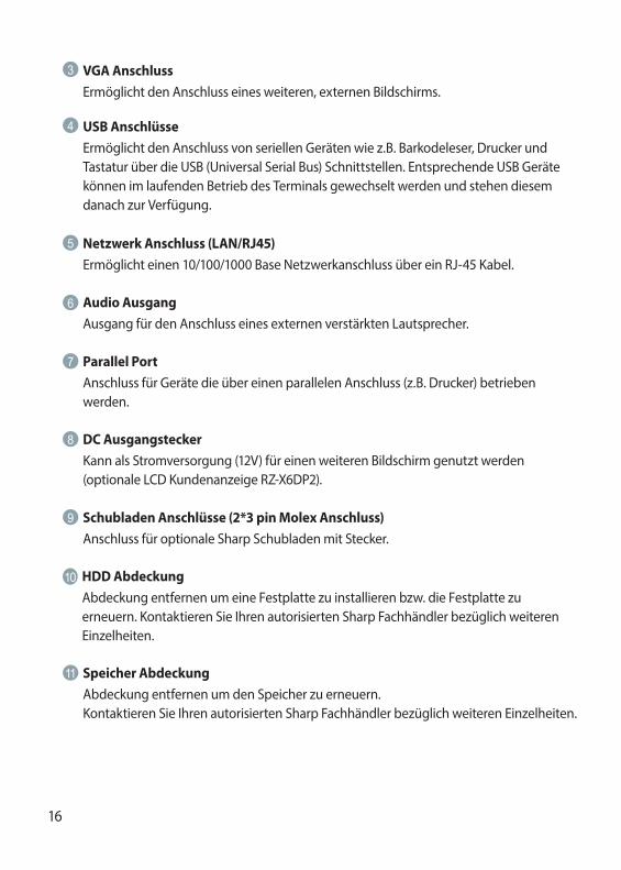
USB AnschlüsseErmöglicht den Anschluss von seriellen Geräten wie z.B. Barkodeleser, Drucker und Tastatur über die USB (Universal Serial Bus) Schnittstellen. Entsprechende USB Geräte können im laufenden Betrieb des Terminals gewechselt werden und stehen diesem danach zur Verfügung.
4
Netzwerk Anschluss (LAN/RJ45)Ermöglicht einen 10/100/1000 Base Netzwerkanschluss über ein RJ-45 Kabel.
5
Audio AusgangAusgang für den Anschluss eines externen verstärkten Lautsprecher.
6
DC AusgangsteckerKann als Stromversorgung (12V) für einen weiteren Bildschirm genutzt werden (optionale LCD Kundenanzeige RZ-X6DP2).
8
7 Parallel PortAnschluss für Geräte die über einen parallelen Anschluss (z.B. Drucker) betrieben werden.
10 HDD Abdeckung Abdeckung entfernen um eine Festplatte zu installieren bzw. die Festplatte zu erneuern. Kontaktieren Sie Ihren autorisierten Sharp Fachhändler bezüglich weiteren Einzelheiten.
9 Schubladen Anschlüsse (2*3 pin Molex Anschluss)Anschluss für optionale Sharp Schubladen mit Stecker.
11 Speicher Abdeckung Abdeckung entfernen um den Speicher zu erneuern. Kontaktieren Sie Ihren autorisierten Sharp Fachhändler bezüglich weiteren Einzelheiten.
VGA Anschluss Ermöglicht den Anschluss eines weiteren, externen Bildschirms.
3
17
BEDIENER ANZEIGE
Anzeigewinkel
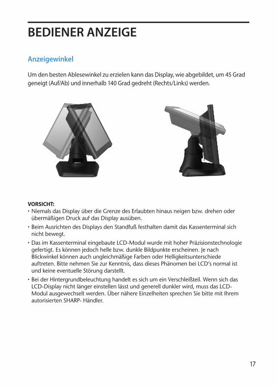
Um den besten Ablesewinkel zu erzielen kann das Display, wie abgebildet, um 45 Grad geneigt (Auf/Ab) und innerhalb 140 Grad gedreht (Rechts/Links) werden.
VORSICHT:• NiemalsdasDisplayüberdieGrenzedesErlaubtenhinausneigenbzw.drehenoderübermäßigenDruckaufdasDisplayausüben.
• BeimAusrichtendesDisplaysdenStandfußfesthaltendamitdasKassenterminalsichnichtbewegt.
• DasimKassenterminaleingebauteLCD-ModulwurdemithoherPräzisionstechnologiegefertigt.Eskönnenjedochhellebzw.dunkleBildpunkteerscheinen.JenachBlickwinkelkönnenauchungleichmäßigeFarbenoderHelligkeitsunterschiedeauftreten.BittenehmenSiezurKenntnis,dassdiesesPhänomenbeiLCD’snormalistundkeineeventuelleStörungdarstellt.
• BeiderHintergrundbeleuchtunghandeltessichumeinVerschleißteil.WennsichdasLCD-Displaynichtlängereinstellenlässtundgenerelldunklerwird,mussdasLCD-Modulausgewechseltwerden.ÜbernähereEinzelheitensprechenSiebittemitIhremautorisiertenSHARP-Händler.
18
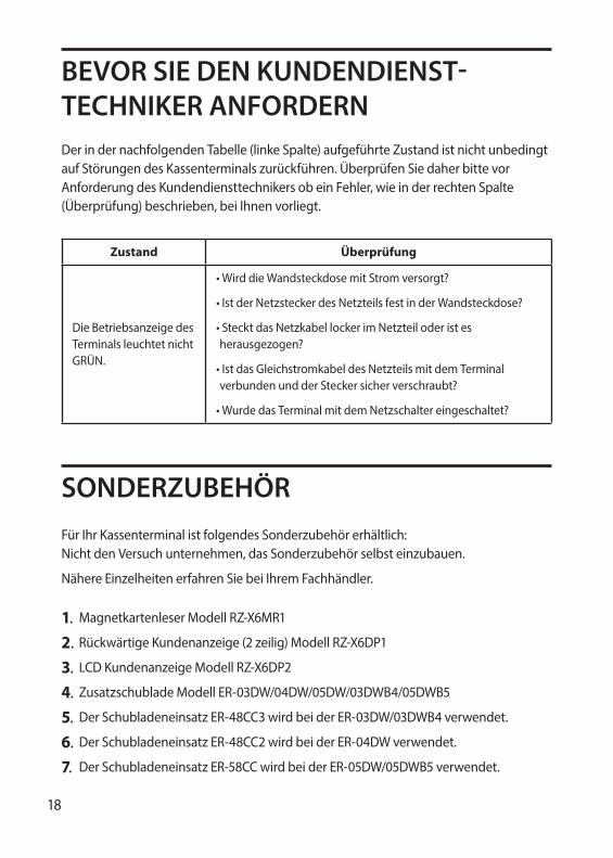
BEVOR SIE DEN KUNDENDIENST-TECHNIKER ANFORDERNDer in der nachfolgenden Tabelle (linke Spalte) aufgeführte Zustand ist nicht unbedingt auf Störungen des Kassenterminals zurückführen. Überprüfen Sie daher bitte vor Anforderung des Kundendiensttechnikers ob ein Fehler, wie in der rechten Spalte (Überprüfung) beschrieben, bei Ihnen vorliegt.
Zustand Überprüfung
Die Betriebsanzeige des Terminals leuchtet nicht GRÜN.
•WirddieWandsteckdosemitStromversorgt?
•IstderNetzsteckerdesNetzteilsfestinderWandsteckdose?
•StecktdasNetzkabellockerimNetzteiloderistesherausgezogen?
•IstdasGleichstromkabeldesNetzteilsmitdemTerminalverbundenundderSteckersicherverschraubt?
•WurdedasTerminalmitdemNetzschaltereingeschaltet?
SONDERZUBEHÖRFür Ihr Kassenterminal ist folgendes Sonderzubehör erhältlich: Nicht den Versuch unternehmen, das Sonderzubehör selbst einzubauen.
Nähere Einzelheiten erfahren Sie bei Ihrem Fachhändler.
1. Magnetkartenleser Modell RZ-X6MR1
2. Rückwärtige Kundenanzeige (2 zeilig) Modell RZ-X6DP1
3. LCD Kundenanzeige Modell RZ-X6DP2
4. Zusatzschublade Modell ER-03DW/04DW/05DW/03DWB4/05DWB5
5. Der Schubladeneinsatz ER-48CC3 wird bei der ER-03DW/03DWB4 verwendet.
6. Der Schubladeneinsatz ER-48CC2 wird bei der ER-04DW verwendet.
7. Der Schubladeneinsatz ER-58CC wird bei der ER-05DW/05DWB5 verwendet.
19
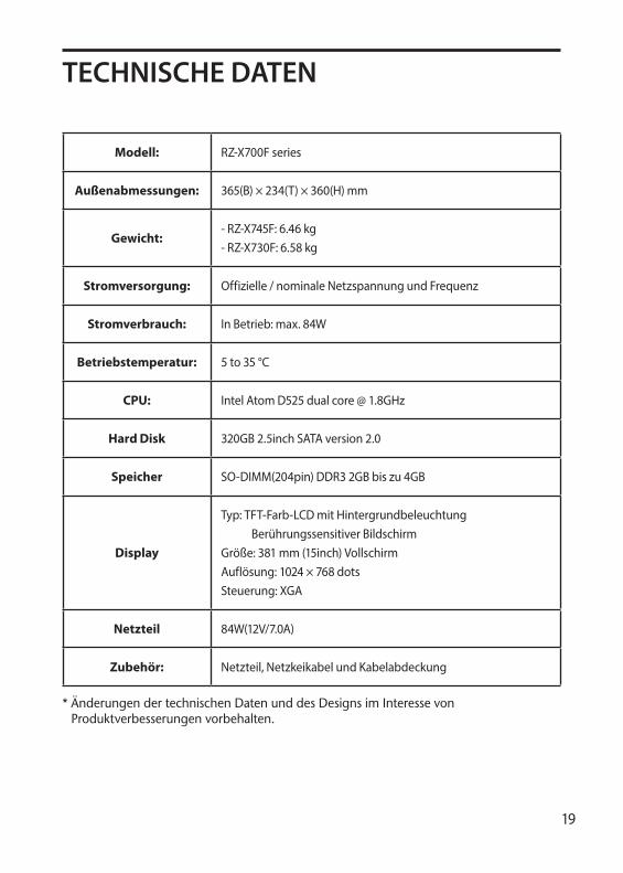
TECHNISCHE DATEN
Modell: RZ-X700F series
Außenabmessungen: 365(B) × 234(T) × 360(H) mm
Gewicht:- RZ-X745F: 6.46 kg- RZ-X730F: 6.58 kg
Stromversorgung: Offizielle / nominale Netzspannung und Frequenz
Stromverbrauch: In Betrieb: max. 84W
Betriebstemperatur: 5 to 35 °C
CPU: Intel Atom D525 dual core @ 1.8GHz
Hard Disk 320GB 2.5inch SATA version 2.0
Speicher SO-DIMM(204pin) DDR3 2GB bis zu 4GB
Display
Typ: TFT-Farb-LCD mit Hintergrundbeleuchtung Berührungssensitiver BildschirmGröße: 381 mm (15inch) VollschirmAuflösung: 1024 × 768 dotsSteuerung: XGA
Netzteil 84W(12V/7.0A)
Zubehör: Netzteil, Netzkeikabel und Kabelabdeckung
*ÄnderungendertechnischenDatenunddesDesignsimInteressevonProduktverbesserungenvorbehalten.

20
21
INTRODUCTION
IMPORTANT
Nous vous remercions beaucoup pour votre achat du Terminal de Point de Vente SHARP.
Veuillez lire attentivement ce Manuel d’Utilisation avant d’utiliser votre Terminal de Point de Vente.
Veuillez conserver ce Manuel pour une référence ultérieure.
• Installez ce Terminal de Point de Vente dans un endroit qui ne soit pas soumis à des radiations directes, à des changements de température inhabituels et à une humidité élevée ni l’exposer à de l’eau ou à d’autres liquides. Une installation dans de pareils endroits risquerait d’endommager le boîtier et les éléments électriques.
• Ne pas faire tomber ce Terminal de Point de Vente ou lui faire subir n’importe quelle forte secousse. Cela risquerait d’endommager le Terminal ainsi que le disque dur qui y est installé.
• Ne pas appliquer une pression excessive sur l’écran. Ne pas utiliser un objet avec une pointe effilée sur l’écran. Cela risque d’endommager l’écran de l’affichage à cristaux liquides.
• La prise de courant murale devra être installée a proximité de l’équipement et devra être facilement accessible. Pour obtenir une mise hors-circuit totale, débrancher la fiche de courant secteur de la prise murale.
• Le Terminal de Point de Vente peut être branché sur n’importe quelle prise de courant murale ordinaire [tension officielle (nominale)]. D’autres appareillages électriques utilisés sur le même circuit électrique peuvent entraîner un fonctionnement défectueux du Terminal de Point de Vente.
Fran
çais

22
• Les fentes, les ouvertures, ainsi que l’arrière du carter sont pourvus d’une ventilation.Afin d’assurer le bon fonctionnement de votre système et le protéger d’une surchauffe, ces ouvertures ne doivent être ni bloquées, ni recouvertes.
• Merci de respecter le conseil qui suit lorsqu’un tiroir optionnel est utilisé: Les éléments du tiroir doivent être solidement fixés à la plate-forme, afin d’éviter l’instabilité du système lorsque les tiroirs sont ouverts.
• Avant de connecter un périphérique aux ports COM électriquement, éteindre le terminal et le débrancher de la prise électrique. Note: Le voltage par défaut du Pin 9 des COM2 et COM3 est de 5V.
Niveau de bruit: 37,3 dB(A) Mesuré sleon la norme EN ISO 7779:2001
[Valeur de crête à l'ouverture du tiroir caisse en option: 74,1 dB(A)]
23
TABLE DES MATIERES
VUE D’ENSEMBLE 24
AFFICHAGE 27
AVANT D’APPELER POUR UN DEPANNAGE 28
LISTE DES OPTIONS 28
DONNEES TECHNIQUES 29
Copyright• Le Copyright de ce manuel appartient à SHARP Corporation.
• Ce manuel ne peut être reproduit entièrement ou partiellement sans permission explicite de SHARP Corporation.
Marques déposées • Intel est la marque déposée d'Intel Corporation.
• Microsoft et Windows sont des marques déposées de la Société Microsoft.
• Toutes autres marques de fabriques sont la propriété des Sociétés respectives.

24
VUE D’ENSEMBLE
De Face
Ecran d’affichage et d’opération (dalle tactile)Ecran TFT-LCD 15 pouces avec dalle tactile. Permet l’affichage des données et l’interaction grâce à la dalle tactile.
1
Interrupteur Une fois le terminal branché à une alimentation électrique, appuyer sur l’interrupteur pour allumer le terminal.
2
Témoin d’activité disque durUn voyant lumineux (LED) s’allume lorsque le système lit ou écrit sur le disque dur.
3
Témoin d’alimentationUn voyant lumineux (LED) s’allume lorsque le système est en marche.
4
2
1
43 5
6

25
Réglage de la luminosité Sert à ajuster la luminosité de l’écran.
5
Lecteur de carte magnétique (option) Permet la lecture de cartes à piste magnétique.
6
Aperçu des connectiques arrières
Ports série 1,2,3,4Permettent la connexion de périphériques comme un afficheur client, un lecteur de codes à barres, ou une imprimante série.
1
Note:• LevoltagepardéfautduPin9desCOM2etCOM3estde5V.Pourplusd’informations,veuillezcontactervotrerevendeurSHARP.
Entrée DC Jack (adaptateur AC/DC)Afin d'alimenter électriquement le système, connecter à cet endroit l'adaptateur AD/DC fourni (12V/7.0A).
2
2 3 4 1 6 981
10
11
5 7
26
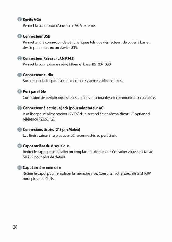
Connecteur USBPermettent la connexion de périphériques tels que des lecteurs de codes à barres, des imprimantes ou un clavier USB.
4
Connecteur Réseau (LAN RJ45)Permet la connexion en série Ethernet base 10/100/1000.
5
Connecteur audio Sortie son « jack » pour la connexion de système audio externes.
6
Connecteur électrique jack (pour adaptateur AC)A utiliser pour l'alimentation 12V DC d'un second écran (écran client 10'' optionnel référence RZX6DP2).
8
7 Port parallèleConnexion de périphériques telles que des imprimantes en communication parallèle.
10 Capot arrière du disque durRetirer le capot pour installer ou remplacer le disque dur. Consulter votre spécialiste SHARP pour plus de détails.
9 Connexions tiroirs (2*3 pin Molex)Les tiroirs caisse Sharp peuvent être connectés au port tiroir.
11 Capot arrière mémoireRetirer le capot pour remplacer la mémoire vive. Consulter votre spécialiste SHARP pour plus de détails.
Sortie VGAPermet la connexion d’une écran VGA externe.
3

27
AFFICHAGE
Angle d’affichage
L’écran peut être pivoté pour un meilleur angle de vue. L’angle peut être ajusté de 140 degrés gauche / droite et 45 degrés haut / bas comme illustré sur le dessin.
Avertissement:• Nepastournerl’écranplusloinquel’anglederotationmaximum.Nepasexercerdepressionexcessivesurl’écran.
• Veilleràmaintenirlabaseduterminallorsquevousréglerl’écranpournepasfairebougerleterminal.
• LemoduleLCDdeceterminalestfabriquégrâceàunetechnologiedehauteprécision.Cependant,despixelsbrillantsoublancspeuventapparaître.Toutcommeunedéformationdecouleuroudeluminositépeuventapparaîtresuivantl’angledevision.VeuilleznoterquecetypedephénomèneestcommunpourlesécransLCDetpeutnepasprovenird’undéfaut.
• Lesystèmederétroéclairagedel’écranestdisponibleenpiècedétachée.• Lorsquel’écranLCDnepeutplusêtreajustéetdevientplussombre,vousdevriezremplacerlemoduleLCD.ConsultervotrerevendeuragrééSHARPpourplusdedétails.

28
AVANT D’APPELER POUR UNDEPANNAGEL’évènement mentionné dans la colonne de gauche ci-dessous n’indique pas nécessairement un problème fonctionnel du terminal. Veuillez vérifier les éléments listés dans la colonne de droite « Vérifications » avant d’appeler votre service technique.
Evènement Vérifications
Le témoin d’alimentation n’est pas éclairé.
•Est-cequelapriseélectriqueestbienalimentée?•Est-cequelecordonélectriqueduterminalestbienconnectéàlaprise(murale)?•Est-cequelecordond’alimentationestbienconnectéautransformateur?•Est-cequelecordonélectriqueestbienbranché sur la prise « jack » d’alimentation du terminal?•Est-cequel’interrupteurduterminalestbiensur«on»?
LISTE DES OPTIONSPour votre Terminal de Point de Vente, les options suivantes sont disponibles: N’essayez pas d’installer vous-même ces options.
Pour les détails, consultez votre revendeur SHARP.
1. Lecteur de cartes magnétiques modèle RZ-X6MR1
2. Afficheur client arrière 2 lignes modèle RZ-X6DP1
3. Ecran client LCD 10.4'' RZX6DP2
4. Tiroir auxiliaire Modèle ER-03DW/04DW/05DW/03DWB4/05DWB5
5. Le casier pour l’argent ER-48CC3 est utilisé pour le ER-03DW/03DWB4
6. Le casier pour l’argent ER-48CC2 est utilisé pour le ER-04DW
7. Le casier pour l’argent ER-58CC est utilisé pour le ER-05DW /05DWB5

29
DONNEES TECHNIQUES
Modèle: RZ-X700F series
Dimensions extérieures 365(L) × 234(P) × 360(H) mm
Poids- RZ-X745F: 6.46 kg- RZ-X730F: 6.58 kg
Alimentation Tension et fréquence officielles (nominales)
Consommation En opération: 84W
Température de fonctionnement
5 à 35 °C
Processeur central Intel Atom D525 dual core @ 1.8GHz
Disque dur 320GB 2.5inch SATA version 2.0
Mémoire SO-DIMM(204pin) DDR3 2GB jusqu'à 4GB
Affichage
Type: Ecran à cristaux liquides couleur à TFT avec éclairage arrière Surface à effleurement analogique
Dimension: 381 mm (15 pouce) Ecran intégralRésolution: 1024 × 768 pointsCommande: XGA
AC / DC Adaptateur 84W(12V/7.0A)
Accessoires AC Adaptateur, AC câble et Cache câbles
* Les données techniques et le design peuvent être l’objet de modifications sans avertissement préalable, en vue d’une amélioration de la machine.

30

31
Espa
ñolINTRODUCCION
IMPORTANTE
Muchas gracias por la adquisición del Terminal SHARP POS.Lea atentamente este manual antes de poner en funcionamiento el terminal POS. Guarde este manual para poderlo consultar en el futuro.
• Instale este terminal en un lugar que no esté sujeto a radiación directa de calor, a cambios anormales de temperaturas, a alta humedad, ni a agua u otros líquidos. La instalación en cualquier lugar así puede causar daños tanto en el exterior como en los componentes electrónicos
• No permita que este terminal se caiga al suelo ni que reciba golpes fuertes.Esto podría causar daños en el terminal y en el disco duro que lleva instalado
• No aplique presión excesiva en la pantalla. No emplee objetos puntiagudos sobre la misma. Esto podría causar daños en el visualizador LCD.
• El terminal POS puede enchufarse a cualquier toma estándar de la pared (tensión oficial/nominal). Otros aparatos eléctricos que puedan estar enchufados en el mismo circuito eléctrico, pueden causar un mal funcionamiento del terminal POS.
• Para una desconexión eléctrica completa, desenchufe la clavija de CA de la toma de corriente de la pared.
• Las ranuras y aberturas en la carcasa y en la parte posterior son para la ventilación.Para asegurar la fiabilidad del sistema y protegerlo del sobrecalentamiento estas aberturas no deben ser bloqueadas ni cubiertas.
• Por favor, observar lo siguiente cuando se usa un cajón opcional:Los cajones deberían ser fijados firmemente a la plataforma de sujección para prevenir su inestabilidad cuando sean abiertos.
• Por favor, apagar el terminal y desconectarlo de la corriente antes de conectar o desconectar dispositivos externos de los puertos COM. Nota. El voltaje por defecto en el Pin 9 del COM2 / COM3 es de 5V.
Nivel de ruido: 37,3 dB(A) Medido conforme a EN ISO 7779:2001
[Valor máximo al abrir el cajón opcional de la caja: 74,1 dB(A)]
32
INDICE
VISIÓN GENERAL DEL SISTEMA 33
VISUALIZADOR 36
ANTES DE SOLICITAR EL SERVICIO TECNICO 37
LISTA DE OPCIONES 37
ESPECIFICACIONES 38
Copyright• El copyright de este manual pertenece a SHARP Corporation.
• Este manual no podrá ser reproducido total o parcialmente sin el expreso permiso de SHARP Corporation.
Marcas Registradas• Intel es la marca registrada de Intel Corporation.
• Microsoft y Windows son marcas registradas de Microsoft Corporation.
• Todas las demas marcas son propiedad de las respectivas compañias.

33
VISIÓN GENERAL DEL SISTEMA
Vista Frontal
Display Operativo (Panel Táctil)Pantalla táctil de 15 pulgadas TFT-LCD . Muestra el status operativo del sistema, el cual puede ser ajustado mediante la pantalla táctil.
1
Botón de EncendidoDespués de conectar el terminal a la corriente eléctrica, pulse el botón de encendido para conectarlo.
2
Indicador HDD Se ilumina un LED cuando el disco duro está leyendo o escribiendo datos.
3
Indicador de CorrienteSe ilumina un LED cuando el sistema está encendido.
4
2
1
43 5
6

34
LCD Brightness ControlPara el ajuste del brillo de la pantalla (aumentar/disminuir).
5
Lector de Banda Magnética (Opcional)Para lectura de tarjetas de banda magnética.
6
Vista Posterior /Puertos IO
Puerto Serie 1,2,3,4Para conectar dispositivos como display de cliente, scanner de código de barras, o impresoras de tickets que tengan interface serie.
1
Nota:• ElvoltajepordefectoenelPin9delCOM2/COM3esde5V.Paramásinformación,porfavorconsulteasuDistribuidorSHARPautorizado.
Jack entrada DC (para fuente de alimentación AC )Para alimentar el sistema, por favor conecte aquí el adaptador de AC/DC suministrado (12V/7.0A).
2
2 3 4 1 6 981
10
11
5 7

35
Conector USB Se pueden conectar periféricos como scanners, impresoras y teclados a los conectores USB (Universal Serial Bus) . Los puertos USB son conectables plug and play para todos los periféricos.
4
Conector LAN (RJ45)Se conecta a este puerto un cable RJ-45 para Conexión Base Ethernet 10/100/1000.
5
Audio jack Se puede conectar al jack un altavoz externo de sonido.
6
Jack salida (DC 12V) Puede utilizar los 12 voltios para alimentar un segundo monitor (opcional).
8
9 Puertos de Cajón (2*3 pin Molex)Opcionalmente se pueden conectar cajones portamonedas Sharp al puerto de cajón.
7 Puerto Paralelo Se pueden conectar dispositivos al Puerto paralelo como, por ejemplo, impresoras.
10 Tapa trasera del disco duroQuitar la tapa para instalar o reemplazar el disco duro. Consulte a su distribuidor autorizado SHARP para más detalles.
Conector VGA Para conectar un cable VGA para un 2nd monitor
3
11 Tapa trasera de memoriaQuitar la tapa para acceder a la memoria. Consultar a su distribuidor Sharp.
36
VISUALIZADOR
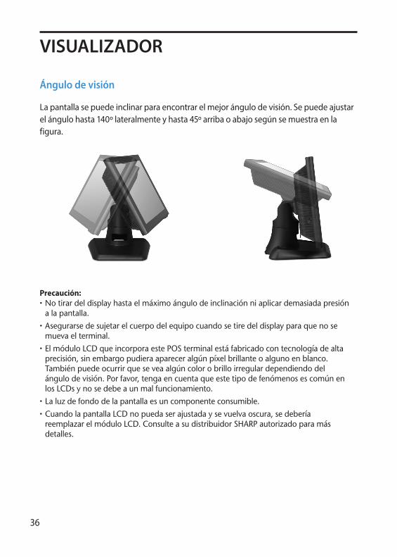
Ángulo de visión
La pantalla se puede inclinar para encontrar el mejor ángulo de visión. Se puede ajustar el ángulo hasta 140º lateralmente y hasta 45º arriba o abajo según se muestra en la figura.
Precaución:• Notirardeldisplayhastaelmáximoángulodeinclinaciónniaplicardemasiadapresiónalapantalla.
• Asegurarsedesujetarelcuerpodelequipocuandosetiredeldisplayparaquenosemuevaelterminal.
• ElmóduloLCDqueincorporaestePOSterminalestáfabricadocontecnologíadealtaprecisión,sinembargopudieraapareceralgúnpíxelbrillanteoalgunoenblanco.Tambiénpuedeocurrirqueseveaalgúncolorobrilloirregulardependiendodelángulodevisión.Porfavor,tengaencuentaqueestetipodefenómenosescomúnenlosLCDsynosedebeaunmalfuncionamiento.
• Laluzdefondodelapantallaesuncomponenteconsumible.• CuandolapantallaLCDnopuedaserajustadaysevuelvaoscura,sedeberíareemplazarelmóduloLCD.ConsulteasudistribuidorSHARPautorizadoparamásdetalles.
37
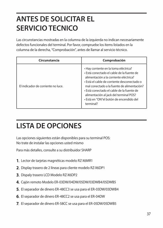
ANTES DE SOLICITAR ELSERVICIO TECNICOLas circunstancias mostradas en la columna de la izquierda no indican necesariamente defectos funcionales del terminal. Por favor, compruebe los ítems listados en la columna de la derecha, “Comprobación”, antes de llamar al servicio técnico.
Circunstancia Comprobación
El indicador de corriente no luce.
•Haycorrienteenlatomaeléctrica?•Estáconectadoelcabledelafuentedealimentaciónalacorrienteeléctrica?•Estáelcabledecorrientedesconectadoomalconectadoalafuentedealimentación?•EstáconectadoelcabledelafuentedealimentaciónaljackdelterminalPOS?•Estáen“ON”elbotóndeencendidodelterminal?
LISTA DE OPCIONESLas opciones siguientes están disponibles para su terminal POS: No trate de instalar las opciones usted mismo
Para más detalles, consulte a su distribuidor SHARP
1. Lector de tarjetas magnéticas modelo RZ-X6MR1
2. Display trasero de 2 líneas para cliente modelo RZ-X6DP1
3. Dispaly trasero LCD Modelo RZ-X6DP2
4. Cajón remoto Modelo ER-03DW/04DW/05DW/03DWB4/05DWB5
5. El separador de dinero ER-48CC3 se usa para el ER-03DW/03DWB4
6. El separador de dinero ER-48CC2 se usa para el ER-04DW
7. El separador de dinero ER-58CC se usa para el ER-05DW/05DWB5
38
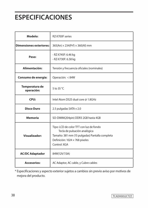
ESPECIFICACIONES
Modelo: RZ-X700F series
Dimensiones exteriores: 365(An) × 234(Prf) × 360(Al) mm
Peso:- RZ-X745F: 6.46 kg- RZ-X730F: 6.58 kg
Alimentación: Tensión y frecuencia oficiales (nominales)
Consumo de energía: Operación: < 84W
Temperatura de operación: 5 to 35 °C
CPU: Intel Atom D525 dual core @ 1.8GHz
Disco Duro 2.5 pulgadas SATA v 2.0
Memoria SO-DIMM(204pin) DDR3 2GB hasta 4GB
Visualizador:
Tipo: LCD de color TFT con luz de fondo Tecla de pulsación analógica
Tamaño: 381 mm (15 pulgadas) Pantalla completa Definición: 1024 × 768 píxelesControl: XGA
AC/DC Adaptador 84W(12V/7.0A)
Accesorios: AC Adaptor, AC cable, y Cubre cables
TCADH0052CTZZ
* Especificaciones y aspecto exterior sujetos a cambios sin previo aviso por motivos de mejora del producto.