rw series - bi-metallic thermal overload · pdf filegeneral information circuit protection...
TRANSCRIPT

General
Inform
ation
Circuit
Pro
tection
Disco
nnect S
witches
Mo
tor
Pro
tec
tors
Overlo
ads
Relays
Pushb
uttons
and P
ilot
Lights
Terminal
Blo
cksC
ontacto
rsP
ow
er Facto
r C
orrectio
n
Enclo
sed
Starters
204 | 1-800-ASK4WEG | www.weg.net/us Data is subject to change without notice.
Overloads
Ap
pend
ixA
Ap
pend
ixB
RW Series - Bi-Metallic
An extended operational service life is one of the main features you can find in RW overload relays. WEG’s RW Thermal Overload Relays are designed for use with, and as perfect complement to, WEG contactors. Effectively, RW overload relays can be mounted directly under WEG contactors, assuring electrical and mechanical operation as an open across-the-line starter. Accessories are also available for separate mounting.
Standard Features• 2 and 3 pole versions available• Direct mounting to WEG contactors with no accessory. (Accessories also available for separate mounting)• Phase loss & current unbalance sensitivity protection• Class 10 Trip characteristics• Selectable RESET button (auto or manual)• Isolated 1NO & 1NC auxiliary contacts
Thermal Overload Relays
RW Series Catalog Number Sequence
U004
Chart intended for reference only and not to create part numbers.
RW117U080: 63…80AU112: 90…112A
RW317U150: 100…150AU420: 275…420A
DOO4: 0,28…0,40AU032: 11…32A
RW67U040: 25…40AU080: 63…80A
For more details refer to selection table
RW407U600: 400…600AU840: 560…840A
3 -
RW17D004: 0,28…0,40AU032: 11…32A
RW27
Overload Setting Current
27-1D: to use with CWM9…2517-2D: to use with CWC025
RW 27-1D
407-1D: to use with CWM400…800
Frame, Size and Terminal Type
3: 3NO Power Poles2: 2NO Power Poles
Power Pole
27-2D: to use with CWB9...3827-2D: to use with CWB9...3867-1D: to use with CWM32…40117-1D: to use with CWM95…105117-2D: to use with CWM112…150317-1D: to use with CWM112…300
Overload Relay SeriesRW: Thermal Overload Relay
17-1D: to use with CWC07…016
Po
wer
Fact
or
Co
rrec
tio
n
Term
inal
B
lock
sP
ush
bu
tto
ns
an
d P
ilot
Lig
hts
Ove
rlo
ads
Co
ntac
tors
Mo
tor
Pro
tect
ors
Dis
conn
ect
Sw
itch
esR
elay
sC
ircu
itP
rote
ctio
nG
ener
al
Info
rmat
ion
Enc
lose
d
Sta
rter
s
WEG Automation - Products and Solutions | 205Data is subject to change without notice.
Overloads
Ap
pen
dix
AA
pp
end
ixB
RW Series - Bi-Metallic
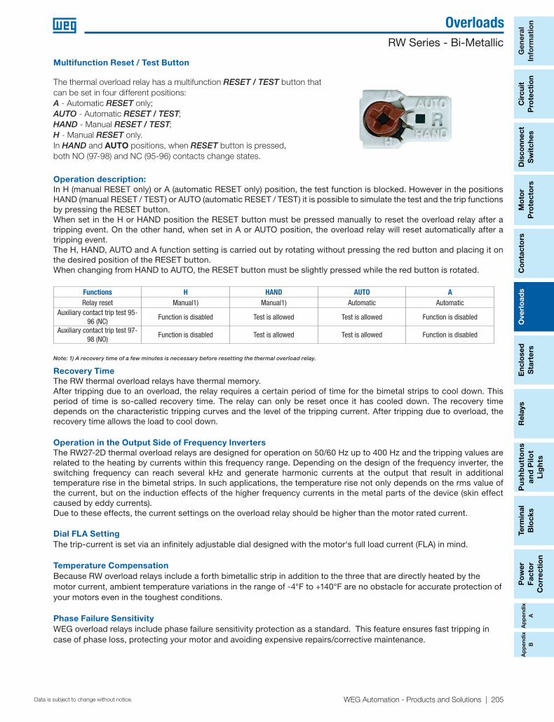
Multifunction Reset / Test Button
Operation description: In H (manual RESET only) or A (automatic RESET only) position, the test function is blocked. However in the positions HAND (manual RESET / TEST) or AUTO (automatic RESET / TEST) it is possible to simulate the test and the trip functions by pressing the RESET button. When set in the H or HAND position the RESET button must be pressed manually to reset the overload relay after a tripping event. On the other hand, when set in A or AUTO position, the overload relay will reset automatically after a tripping event. The H, HAND, AUTO and A function setting is carried out by rotating without pressing the red button and placing it on the desired position of the RESET button. When changing from HAND to AUTO, the RESET button must be slightly pressed while the red button is rotated.
Functions H HAND AUTO ARelay reset Manual1) Manual1) Automatic Automatic
Auxiliary contact trip test 95-96 (NC)
Function is disabled Test is allowed Test is allowed Function is disabled
Auxiliary contact trip test 97-98 (NO)
Function is disabled Test is allowed Test is allowed Function is disabled
Recovery Time The RW thermal overload relays have thermal memory.After tripping due to an overload, the relay requires a certain period of time for the bimetal strips to cool down. This period of time is so-called recovery time. The relay can only be reset once it has cooled down. The recovery time depends on the characteristic tripping curves and the level of the tripping current. After tripping due to overload, the recovery time allows the load to cool down.
Operation in the Output Side of Frequency InvertersThe RW27-2D thermal overload relays are designed for operation on 50/60 Hz up to 400 Hz and the tripping values are related to the heating by currents within this frequency range. Depending on the design of the frequency inverter, the switching frequency can reach several kHz and generate harmonic currents at the output that result in additional temperature rise in the bimetal strips. In such applications, the temperature rise not only depends on the rms value of the current, but on the induction effects of the higher frequency currents in the metal parts of the device (skin effect caused by eddy currents).Due to these effects, the current settings on the overload relay should be higher than the motor rated current.
Dial FLA SettingThe trip-current is set via an infinitely adjustable dial designed with the motor‘s full load current (FLA) in mind.
Temperature CompensationBecause RW overload relays include a forth bimetallic strip in addition to the three that are directly heated by the motor current, ambient temperature variations in the range of -4°F to +140°F are no obstacle for accurate protection of your motors even in the toughest conditions.
Phase Failure SensitivityWEG overload relays include phase failure sensitivity protection as a standard. This feature ensures fast tripping in case of phase loss, protecting your motor and avoiding expensive repairs/corrective maintenance.
The thermal overload relay has a multifunction RESET / TEST button that can be set in four different positions: A - Automatic RESET only; AUTO - Automatic RESET / TEST; HAND - Manual RESET / TEST; H - Manual RESET only. In HAND and AUTO positions, when RESET button is pressed, both NO (97-98) and NC (95-96) contacts change states.
Note: 1) A recovery time of a few minutes is necessary before resetting the thermal overload relay.

General
Inform
ation
Circuit
Pro
tection
Disco
nnect S
witches
Mo
tor
Pro
tec
tors
Overlo
ads
Relays
Pushb
uttons
and P
ilot
Lights
Terminal
Blo
cksC
ontacto
rsP
ow
er Facto
r C
orrectio
n
Enclo
sed
Starters
206 | 1-800-ASK4WEG | www.weg.net/us Data is subject to change without notice.
Overloads
Ap
pend
ixA
Ap
pend
ixB
RW Series - Bi-Metallic
Three-pole Thermal Overload Relay Class 10
Matching ContactorSetting Range [A]
Max. Fuse [A] Catalog Number List Price Multiplier Min. Max.
CWC07…CWC016CWCA0
(Mini-contactor)
0.28 0.40 15 RW17-1D3-D004 $46
Z2
0.40 0.63 15 RW17-1D3-C063 $460.56 0.80 15 RW17-1D3-D008 $460.80 1.20 15 RW17-1D3-D012 $461.20 1.80 15 RW17-1D3-D018 $461.80 2.80 15 RW17-1D3-D028 $462.80 4.00 15 RW17-1D3-U004 $464.00 6.30 25 RW17-1D3-D063 $465.60 8.00 30 RW17-1D3-U008 $467.00 10.0 40 RW17-1D3-U010 $468.00 12.5 50 RW17-1D3-D125 $4610.0 15.0 60 RW17-1D3-U015 $4611.0 17.0 60 RW17-1D3-U017 $46
CWC025 (Mini-contactor)15.0 23.0 90 RW17-2D3-U023 $46
22.0 32.0 100 RW17-2D3-U032 $46
CWM9...CWM40CWM9N...CWM32N
0.28 0.40 15 RW27-1D3-D004 $500.40 0.63 15 RW27-1D3-C063 $500.56 0.80 15 RW27-1D3-D008 $500.80 1.20 15 RW27-1D3-D012 $501.20 1.80 15 RW27-1D3-D018 $501.80 2.80 15 RW27-1D3-D028 $502.80 4.00 15 RW27-1D3-U004 $504.00 6.30 25 RW27-1D3-D063 $505.60 8.00 30 RW27-1D3-U008 $507.00 10.0 40 RW27-1D3-U010 $508.00 12.5 50 RW27-1D3-D125 $5010.0 15.0 60 RW27-1D3-U015 $5011.0 17.0 60 RW27-1D3-U017 $5015.0 23.0 90 RW27-1D3-U023 $5022.0 32.0 90 RW27-1D3-U032 $50
CWM32...CWM40CWM32N
25.0 40.0 90 RW67-1D3-U040 $8732.0 50.0 125 RW67-1D3-U050 $94
CWM50...CWM80CWM50N
25.0 40.0 90 RW67-2D3-U040 $9532.0 50.0 125 RW67-2D3-U050 $9540.0 57.0 150 RW67-2D3-U057 $9550.0 63.0 150 RW67-2D3-U063 $9557.0 70.0 175 RW67-2D3-U070 $11263.0 80.0 175 RW67-2D3-U080 $112
CWM95...CWM105CWM95N
63.0 80.0 200 RW117-1D3-U080 $15075.0 97.0 225 RW117-1D3-U097 $19290.0 112 250 RW117-1D3-U112 $192
CWM112...CWM150CWM150N
75.0 97 225 RW117-2D3-U097 $23290.0 112 250 RW117-2D3-U112 $232
CWM112…CWM300CWM300N
100 150 300 RW317-1D3-U150 $285140 215 350 RW317-1D3-U215 $285200 310 500 RW317-1D3-U310 $320
CWM400...CWM800275 420 700 RW317-1D3-U420 $320400 600 1000 RW407-1D3-U600 $690560 840 1250 RW407-1D3-U840 $690
Note: RW117-2D, RW317-1D and RW407-1D are for separate mounting - Connector links for contactors CWM112…CWM300 are available as an accessory on page B-59.
• Adjustable tripping current • Phase-loss sensitivity • Tripping class 10 • Auxiliary contacts 1NO + 1NC• Temperature compensation from -40F to +140F• Hand/Auto/Reset button
For use with CWC and CWM Contactors

Po
wer
Fact
or
Co
rrec
tio
n
Term
inal
B
lock
sP
ush
bu
tto
ns
an
d P
ilot
Lig
hts
Ove
rlo
ads
Co
ntac
tors
Mo
tor
Pro
tect
ors
Dis
conn
ect
Sw
itch
esR
elay
sC
ircu
itP
rote
ctio
nG
ener
al
Info
rmat
ion
Enc
lose
d
Sta
rter
s
WEG Automation - Products and Solutions | 207Data is subject to change without notice.
Overloads
Ap
pen
dix
AA
pp
end
ixB
RW Series - Bi-Metallic
• Adjustable Trip Current
• Phase Loss Sensitivity
• Trip Class 10
• Built-In Auxiliary Contacts: 1NO + 1NC
• Ambient Temperature Compensation: -4ºF to +140ºF
• Multi-Function Button: Hand/Auto/Reset
Matching ContactorSetting Range [A]
Max. Fuse [A] Catalog Number List Price MultiplierMin. Max.
CWB9 - CWB38
0.28 0.40 15 RW27-2D3-D004 $50
Z2
0.40 0.63 15 RW27-2D3-C063 $50
0.56 0.80 15 RW27-2D3-D008 $50
0.80 1.20 15 RW27-2D3-D012 $50
1.20 1.80 15 RW27-2D3-D018 $50
1.80 2.80 15 RW27-2D3-D028 $50
2.80 4.00 15 RW27-2D3-U004 $50
4.00 6.30 25 RW27-2D3-D063 $50
5.60 8.00 30 RW27-2D3-U008 $50
7.00 10.0 40 RW27-2D3-U010 $50
8.00 12.5 50 RW27-2D3-D125 $50
10.0 15.0 60 RW27-2D3-U015 $50
11.0 17.0 60 RW27-2D3-U017 $50
15.0 23.0 90 RW27-2D3-U023 $50
22.0 32.0 90 RW27-2D3-U032 $50
32.0 40.0 90 RW27-2D3-U040 $60
Three-pole Thermal Overload Relay Class 10
For use with CWB Contactors

General
Inform
ation
Circuit
Pro
tection
Disco
nnect S
witches
Mo
tor
Pro
tec
tors
Overlo
ads
Relays
Pushb
uttons
and P
ilot
Lights
Terminal
Blo
cksC
ontacto
rsP
ow
er Facto
r C
orrectio
n
Enclo
sed
Starters
208 | 1-800-ASK4WEG | www.weg.net/us Data is subject to change without notice.
Overloads
Ap
pend
ixA
Ap
pend
ixB
RW Series - Bi-Metallic
Two-pole Thermal Overload Relays Class 10(used for single phase applications)
• Adjustable tripping current • Phase-loss sensitivity • Tripping class 10 • Auxiliary contacts 1NO + 1NC • Temperature compensation from -40F to +1400F • Hand/Auto/Reset button
Matching ContactorSetting Range [A]
Max. Fuse [A] Catalog Number List Price Multiplier Min. Max.
CWM9...CWM40
0.28 0.40 15 RW27-1D2-D004 $40
Z2
0.40 0.63 15 RW27-1D2-C063 $40
0.56 0.80 15 RW27-1D2-D008 $40
0.80 1.20 15 RW27-1D2-D012 $40
1.20 1.80 15 RW27-1D2-D018 $40
1.80 2.80 15 RW27-1D2-D028 $40
2.80 4.00 15 RW27-1D2-U004 $40
4.00 6.30 25 RW27-1D2-D063 $40
5.60 8.00 30 RW27-1D2-U008 $50
7.00 10.0 40 RW27-1D2-U010 $50
8.00 12.5 50 RW27-1D2-D125 $50
10.0 15.0 60 RW27-1D2-U015 $50
11.0 17.0 60 RW27-1D2-U017 $50
15.0 23.0 90 RW27-1D2-U023 $50
22.0 32.0 90 RW27-1D2-U032 $50
CWM32...CWM4025.0 40.0 90 RW67-1D2-U040 $81
32.0 50.0 125 RW67-1D2-U050 $88
CWM50...CWM80
25.0 40.0 90 RW67-2D2-U040 $95
32.0 50.0 125 RW67-2D2-U050 $95
40.0 57.0 150 RW67-2D2-U057 $95
50.0 63.0 150 RW67-2D2-U063 $95
57.0 70.0 175 RW67-2D2-U070 $105
63.0 80.0 175 RW67-2D2-U080 $105
Note: 1 Availability upon request.
For use with CWC and CWM Contactors

Po
wer
Fact
or
Co
rrec
tio
n
Term
inal
B
lock
sP
ush
bu
tto
ns
an
d P
ilot
Lig
hts
Ove
rlo
ads
Co
ntac
tors
Mo
tor
Pro
tect
ors
Dis
conn
ect
Sw
itch
esR
elay
sC
ircu
itP
rote
ctio
nG
ener
al
Info
rmat
ion
Enc
lose
d
Sta
rter
s
WEG Automation - Products and Solutions | 209Data is subject to change without notice.
Overloads
Ap
pen
dix
AA
pp
end
ixB
RW Series - Bi-Metallic
2 POLE THERMAL OVERLOAD RELAYS - CLASS 10
Matching Contactor Setting Range [A] Max. Fuse [A] Catalog Number List Price Multiplier
Min. Max.
CWB9 - CWB38
0.28 0.40 15 RW27-2D2-D004 $50
Z2
0.40 0.63 15 RW27-2D2-C063 $50
0.56 0.80 15 RW27-2D2-D008 $50
0.80 1.20 15 RW27-2D2-D012 $50
1.20 1.80 15 RW27-2D2-D018 $50
1.80 2.80 15 RW27-2D2-D028 $50
2.80 4 15 RW27-2D2-U004 $50
4 6.30 25 RW27-2D2-D063 $50
5.60 8.00 30 RW27-2D2-U008 $50
7.00 10.0 40 RW27-2D2-U010 $50
8.00 12.5 50 RW27-2D2-D125 $50
10.0 15.0 60 RW27-2D2-U015 $50
11.0 17.0 60 RW27-2D2-U017 $50
15.0 23.0 90 RW27-2D2-U023 $50
22.0 32.0 90 RW27-2D2-U032 $50
32.0 40.0 90 RW27-2D2-U040 $50
Two-pole Thermal Overload Relays Class 10 (used for single phase applications)
• Adjustable tripping current • Phase-loss sensitivity • Tripping class 10 • Auxiliary contacts 1NO + 1NC • Temperature compensation from -40F to +1400F • Hand/Auto/Reset button
For use with CWB Contactors

General
Inform
ation
Circuit
Pro
tection
Disco
nnect S
witches
Mo
tor
Pro
tec
tors
Overlo
ads
Relays
Pushb
uttons
and P
ilot
Lights
Terminal
Blo
cksC
ontacto
rsP
ow
er Facto
r C
orrectio
n
Enclo
sed
Starters
210 | 1-800-ASK4WEG | www.weg.net/us Data is subject to change without notice.
Overloads
Ap
pend
ixA
Ap
pend
ixB
RW Series - Bi-Metallic
Description Mounting on Overload Relays (2 or 3 pole) Catalog Number List Price Multiplier
Enables overload relay to be directly mounted to a back panel via screws or
DIN rail
RW27-1D BF27D $14
Z2RW27-2D BF27-2D $14
RW67-1D and RW67-2D BF67.1D $23RW117-1D BF117D $30
Description Mounting in Cover of Control Panel Catalog Number List Price Multiplier
Enables overload relay to be Reset from control panel, without opening the cover
22 MM Flush Reset PB Blue 'R' CSW-RSBF4R $20Z5
30 MM Flush Reset PB Black 'Reset' CSW30-RSBW $22
Description Contactor Overload Relay Catalog Number List Price Multiplier
Link connectors for easier CWM contactors and RW overload relays
assembly
CWM112 RW117-2D3 GA117D $41
Z2CWM150 RW317-1D3 GA317-1D $68CWM180 RW317-1D3 GA317-2D $70
CWM250 / CWM300 RW317-1D3 GA317-3D $118CWM400 RW317-1D3 GA317-10D $118
External Reset Button
Connector links (3 per package)
Separate Mounting Bracket (not for use with RW27-2D)
Lugs for RW Series (Overload Relay) (3 units per package)
Description / Wire Range Mounting on Overloads Catalog NumberList
PriceMultiplier
(2) 600 MCM...2AWG RW407-2D (400A-840A) LW1-2S600-B $230
Z2600 MCM…4AWG RW317-1D (200A-420A) LW2-S600 $75
300 MCM...6AWG RW317-1D (100A-215A) LW3-S300 $35
Po
wer
Fact
or
Co
rrec
tio
n
Term
inal
B
lock
sP
ush
bu
tto
ns
an
d P
ilot
Lig
hts
Ove
rlo
ads
Co
ntac
tors
Mo
tor
Pro
tect
ors
Dis
conn
ect
Sw
itch
esR
elay
sC
ircu
itP
rote
ctio
nG
ener
al
Info
rmat
ion
Enc
lose
d
Sta
rter
s
WEG Automation - Products and Solutions | 211Data is subject to change without notice.
Overloads
Ap
pen
dix
AA
pp
end
ixB
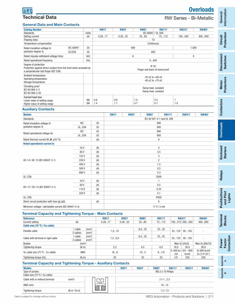
RW Series - Bi-MetallicTechnical Data
Catalog Number RW17 RW27 RW67 RW117 RW317 RW407Standards Units IEC 60947 / UL 508Setting current (A) 0.28...17 0.28...32 25...80 75...112 100...420 400...840Tripping class 10Temperature compensation Continuous
Rated insulation voltage Ui (pollution degree 3)
IEC 60947 (V) 690 1,000
UL/CSA (V) 600
Rated impulse withstand voltage Uimp (kV) 6 8
Rated operational frequency (Hz) 0...400
Degree of protectionProtection against direct contact from the front when actuated by a perpendicular test finger (IEC 536)
IP 20Finger and back-of-hand proof
Ambient temperatureOperating temperatureStorage temperature
-25 oC to +60 oC-40 oC to +70 oC
Climating proofIEC 60 068-2-3IEC 60 068-2-30
Damp heat. constantDamp heat. constant
Current heat lossLower value of setting range Higher value of setting range
(W)(W)
0.91.4
0.91.7
1.54.7
2.34.7
11.9
Auxiliary Contacts
General Data and Main Contacts
Models RW17 RW27 RW67 RW117 RW317 RW407
Standards IEC 60 947-4-1 and UL 508
Rated insulation voltage Ui(pollution degree 3)
IEC (V) 690
UL, CSA (V) 600
Rated operational voltage UeIEC (V) 690
UL, CSA (V) 600
Rated thermal current Ith (θ ≤55 ºC) (A) 6
Rated operational current Ie
AC-14 / AC-15 (IEC 60947-5-1)
24 V (A) 4
60 V (A) 3.5
125 V (A) 3
230 V (A) 2
400 V (A) 1.5
500 V (A) 0.5
690 V (A) 0.3
UL, CSA C600
DC-13 / DC-14 (IEC 60947-5-1)
24 V (A) 1
60 V (A) 0.5
110 V (A) 0.25
220 V (A) 0.1
UL, CSA R300
Short-circuit protection with fuse (gL/gG) (A) 6
Minimum voltage / admissible current (IEC 60947-5-4) 17 V / 5 mA
Terminal Capacity and Tightening Torque - Auxiliary ContactsModels RW17 RW27 RW67 RW117 RW317 RW407Type of screws M3.5 x 10 PhilipsCable size (75 ºC / Cu cable)
Cable with or without terminal (mm²) 2 x 1...2.5
AWG-wire 16...12
Tightening torque (N.m / lb.in) 1.5 / 13
Terminal Capacity and Tightening Torque - Main ContactsReference RW17 RW27 RW67 RW117 RW317 RW407Current setting (A) 0.28...17 0.28...32 25...80 75...112 100...215 200...420 400...840Cable size (75 ºC / Cu cable)
Flexible cable 1 cable (mm2)
1,5...106,0...35 25...35
35...120 95...150 - 2 cables (mm2) - -
Cable with terminal or rigid cable 1 cable (mm2)
1,5...6,06,0...35 25...35
35...120 95...150 - 2 cables (mm2) - -
Busbar (mm2) - Max 2x (25x5) Max 2x (60x10)Tightening torque (N.m) 2,3 4,0 6,0 16,0 26,0 26,0
UL cable size (75 ºC - Cu cable) AWG 16...8 10...3 6...1/03–300 kc-
mil3/0 – 600
kcmil2x 600 kcmil 2x (1/4”x2”)
Tightening torque (UL) (lb.in) 20 35 53 141 230 230

General
Inform
ation
Circuit
Pro
tection
Disco
nnect S
witches
Mo
tor
Pro
tec
tors
Overlo
ads
Relays
Pushb
uttons
and P
ilot
Lights
Terminal
Blo
cksC
ontacto
rsP
ow
er Facto
r C
orrectio
n
Enclo
sed
Starters
212 | 1-800-ASK4WEG | www.weg.net/us Data is subject to change without notice.
Overloads
Ap
pend
ixA
Ap
pend
ixB
RW Series - Bi-Metallic
Technical DataMain Data
Models RW27
Standards IEC 60947-1 and UL 508
Rated insulation voltage Ui (pollution degree 3) IEC 60947-4-1 (V) 690
UL, CSA (V) 600
Rated impulse withstand voltage Uimp (IEC 60947-1) (kV) 6
Rated operational frequency (Hz) 25...400
Use with direct current Yes
Maximum operation per hour (ops./h) 15
Protection degree (IEC 60529) Main contacts IP10
Auxiliary contacts IP20
Frontal IP20
Mounting Direct on the contactor
Resistance to impact (IEC 60068-2-27 - 1/2 sinusoid) (g/ms) 10/11
Ambient temperature Transport and storage -50 ºC...+80 ºC
Operating -20 ºC...+70 ºC
Temperature compensation -20 ºC...+60 ºC
Altitude (m) 2000
Main Contacts
Models RW27
Rated operational voltage Ue IEC 60947-4-1 (V) 690
UL, CSA (V) 600
0.28...0.4 / 2
0.43...0.63 /2
0.56...0.8 / 2
0.8...1.2 / 4
1.2...1.8 / 6
1.8...2.8 / 6
2.8...4 / 10
Setting current / max fuse (gL/gG)1) (A) 4...6.3 / 16
5.6... 8 / 20
7...10 / 25
8...12.5 / 25
10...15 / 35
11...17 / 40
15...23 / 50
22...32 / 63
32...40 / 90
Average power dissipation per pole (W) ≤3

Po
wer
Fact
or
Co
rrec
tio
n
Term
inal
B
lock
sP
ush
bu
tto
ns
an
d P
ilot
Lig
hts
Ove
rlo
ads
Co
ntac
tors
Mo
tor
Pro
tect
ors
Dis
conn
ect
Sw
itch
esR
elay
sC
ircu
itP
rote
ctio
nG
ener
al
Info
rmat
ion
Enc
lose
d
Sta
rter
s
WEG Automation - Products and Solutions | 213Data is subject to change without notice.
Overloads
Ap
pen
dix
AA
pp
end
ixB
RW Series - Bi-Metallic
The derating of the permissible operating current for installation altitudes above 2,000m (6,667 ft) and ambient temperatures over 60ºC (140ºF) is calculated according to:
Total derating = Derating altitude x Derating ambient temperature
Example; Altitude: 3,000 m (10,000 ft) K1 = 0.96Ambient temperature: 70ºC (158ºF) K2 = 0.87
Total current derating = 0.96 x 0.87 = 0.84 x IeIn this case, the maximum rated voltage we can connect to our RW overload relay is 550V.
In order to select the proper overload relay, you have to choose a device with a current range that accommodates: Overload Setting Point = FLA motor / (K1 x K2)
As in the example above, K1 x K2 = 0.84For a motor with FLA = 20Amps
Overload Setting Point = 20 / 0.84 = 23.8Amps
RW Tripping Characteristics
The derating of a RW overload relay has two possible factors:1) Ambient temperature • Temperature compensation considers a factor according to
which the rated current must be reduced when ambient temperature is higher than 60ºC (140ºF).
2) Altitude • Altitude compensation involves both, rated current and voltage. • Current compensation considers a factor according to the
rated current must be reduced. • For voltage, altitude limits the higher operating voltage the
overload relay can be used.
These tripping characteristics show the tripping of RW in relation to the current. They show the mean values of the tolerance ranges at on ambient temperature of 68ºF (20ºC), starting from cold stats. The tripping time of the overload releases at operational temperature is reduced to approximately 25% of the values shown. Under normal operational conditions, all three phases of the RWs should be loaded.
x Setting current
Altitude & Temperature Derating
Temperature Compensation Current Correction ffactor
149°F (65°C) 0.94
158°F (70°C) 0.87
167°F (75°C) 0.81
176°F (80°C) 0.73
Altitude Voltage Correction [Ue]
Up to 2,000m (6,667ft) 690
Up to 3,000m (10,000ft) 550
Up to 4,000m (13,333ft) 480
Up to 5,000m (16,667ft) 420
Meters
General
Inform
ation
Circuit
Pro
tection
Disco
nnect S
witches
Mo
tor
Pro
tec
tors
Overlo
ads
Relays
Pushb
uttons
and P
ilot
Lights
Terminal
Blo
cksC
ontacto
rsP
ow
er Facto
r C
orrectio
n
Enclo
sed
Starters
214 | 1-800-ASK4WEG | www.weg.net/us Data is subject to change without notice.
Overloads
Ap
pend
ixA
Ap
pend
ixB
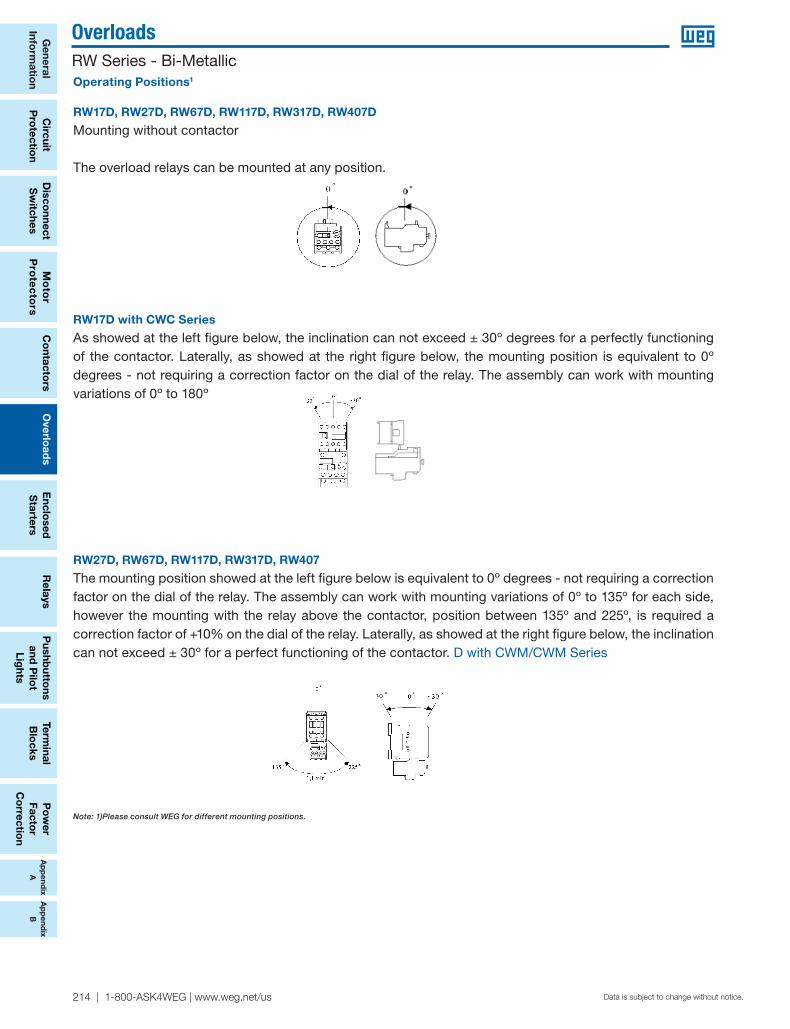
RW Series - Bi-MetallicOperating Positions1
RW17D, RW27D, RW67D, RW117D, RW317D, RW407D
Mounting without contactor
The overload relays can be mounted at any position.
RW17D with CWC Series
As showed at the left figure below, the inclination can not exceed ± 30º degrees for a perfectly functioning of the contactor. Laterally, as showed at the right figure below, the mounting position is equivalent to 0º degrees - not requiring a correction factor on the dial of the relay. The assembly can work with mounting variations of 0º to 180º
RW27D, RW67D, RW117D, RW317D, RW407
The mounting position showed at the left figure below is equivalent to 0º degrees - not requiring a correction factor on the dial of the relay. The assembly can work with mounting variations of 0º to 135º for each side, however the mounting with the relay above the contactor, position between 135º and 225º, is required a correction factor of +10% on the dial of the relay. Laterally, as showed at the right figure below, the inclination can not exceed ± 30º for a perfect functioning of the contactor. D with CWM/CWM Series
Note: 1)Please consult WEG for different mounting positions.
Mounting Position The relay must be mounted on an stable and vibration free surface.
RW17D, RW27D, RW67D, RW117D
RW27D, RW67D, RW117D
RW17D with CAW 04 or CW07
Mounting without contactor
The relays can be mounted at any position.
Mounting with contactor
The mounting position showed at the left �gure below is equivalentto 0º degrees - not requiring a correction factor on the dial of therelay. The assembly can work with mounting variations of 0º to180º, however the mounting with the relay above the contactor,position between 135º and 225º, is required a correction factor of+10% on the dial of the relay. Laterally, as showed at the right�gure below, the inclination can not exceed ± 30º for a perfectfunctioning of the contactor.
As showed at the left �gure below, the inclination can not exceed ±30º degrees for a perfectly functioning of the contactor. Laterally, asshowed at the right �gure below, the mounting position isequivalent to 0º degrees - not requiring a correction factor on thedial of the relay. The assembly can work with mounting variationsof 0º to 180º.

Po
wer
Fact
or
Co
rrec
tio
n
Term
inal
B
lock
sP
ush
bu
tto
ns
an
d P
ilot
Lig
hts
Ove
rlo
ads
Co
ntac
tors
Mo
tor
Pro
tect
ors
Dis
conn
ect
Sw
itch
esR
elay
sC
ircu
itP
rote
ctio
nG
ener
al
Info
rmat
ion
Enc
lose
d
Sta
rter
s
WEG Automation - Products and Solutions | 215Data is subject to change without notice.
Overloads
Ap
pen
dix
AA
pp
end
ixB
RW Series - Bi-Metallic
RW17-1D
45/ [1.77]
71,5
/ [2
.81]
82,45/ [3.25]
57/
[2.2
4]
RW17-2D
45/ [1.77]
71/
[2.8
0]
82.45/ [3.25]
57/
[2.2
4]
RW27
82,5/ [3.25]
51,5
/ [2
.03]
45/ [1.77]
70,5
/ [2
.78]2A
RW27 + BF27
RW67
106/ [4.17]
100/ [3.94]50/ [1.97]
76/
[2.9
9]
50/
[1.9
7]
125A
RW27D
2A
79/
[3.1
1]
45/ [1.77]
60/
[2.3
6]
4,5/
[0.1
8]
6,8/ [0.27]
4,5/
[0.1
8]
35/ [1.38]
5/ [0.20]
RW27D
BF27D92,5/ [3.64]
2A

General
Inform
ation
Circuit
Pro
tection
Disco
nnect S
witches
Mo
tor
Pro
tec
tors
Overlo
ads
Relays
Pushb
uttons
and P
ilot
Lights
Terminal
Blo
cksC
ontacto
rsP
ow
er Facto
r C
orrectio
n
Enclo
sed
Starters
216 | 1-800-ASK4WEG | www.weg.net/us Data is subject to change without notice.
Overloads
Ap
pend
ixA
Ap
pend
ixB
RW Series - Bi-Metallic
RW67 + BF67
RW117-1D RW117-2D
80,5
/ [3
.17]
99,5
/ [3
.92]
75/ [2.95]
24/ [0.94] 24/ [0.94]
8,4/ [0.33]
98,5/ [3.88]
20/
[0.7
9]
40/ [1.57] 3/ [0.12]
200A
106,2/ [4.18]
98,3/ [3.87]
106/
[4.1
7]
7,4/
[0.2
9]
5,4/
[0.2
1]
7,4/ [0.29]
5,4/ [0.21]
56
75/ [2.95]
BF117D
116,
4/ [4
.58]
200A
6,8/ [0.27]4,
5/ [0
.18]
60/
[2.3
6]
7,5/ [0.30]
35/ [1.38]
4,5/
[0.1
8]
5/ [0.20]
50/ [1.97]
71/
[2.8
0]
100/ [3.94]
106/ [4.17]
BF67D
RW67
RW67D
125A

Po
wer
Fact
or
Co
rrec
tio
n
Term
inal
B
lock
sP
ush
bu
tto
ns
an
d P
ilot
Lig
hts
Ove
rlo
ads
Co
ntac
tors
Mo
tor
Pro
tect
ors
Dis
conn
ect
Sw
itch
esR
elay
sC
ircu
itP
rote
ctio
nG
ener
al
Info
rmat
ion
Enc
lose
d
Sta
rter
s
WEG Automation - Products and Solutions | 217Data is subject to change without notice.
Overloads
Ap
pen
dix
AA
pp
end
ixB
RW Series - Bi-MetallicRW317
RW407
110/
[4.3
3]93
/ [3
.66]
130/
[5.1
2]15
5/ [6
.10]
40/ [1.57]
48,5/ [1.91]
120/ [4.72]
7/ [0
.28]
166/ [6.54]
4/ [0.16]
A A
B
355A
250/ [9.84]
162/ [6.38]
260/ [10.24]
150/
[5.9
1]
O5/ [O0
.20]
50/
[1.9
7]11
9/ [4
.69]
60/
[2.3
6]
13/ [0.51]
182,5/ [7.19]
50/ [1.97]
90/ [3.54]
9,5/ [0.37]32/ [1.26]81/ [3.19]
1250A
A
Current ranges A B
100...150A39(1.5) 20(0.8)
140...215A
200...310A45(1.8) 25(1.0)
275...420A