rv 12 electrical schematic instructions - van's · rv‐12 electrical schematic instructions...
TRANSCRIPT

RV‐12 Electrical Schematic Instructions
Step 1: Set your monitor resolution as high as possible.
Step 2: Download "RV‐12 Electrical Systems (XXX).dwg" from the Van's Aircraft web site to your desktop.
Step 3: Open www.autocadws.com in your browser
AutoCAD offers a free cloud based app for the iPad, iPhone, Mac, Android and PC desktop "AutoCAD WS"
The iPad and iPhone app are at http://itunes.apple.com/us/app/autocad‐ws/id393149734?mt=8
NOTE: on an iPad AutoCAD WS App + RV‐12 Electrical Sysytems.dwg uses approximately 42MB of space.
Step 4: Click "Create Account" on the opening screen and work your way through the registration process.

Step 5: Click on the "Open" icon in the upper left part of the window, navigate to the "RV‐12 Electrical Systems (XXX).dwg" on your desktop.
At this point the file has been loaded into the "cloud" and saved on the AutoCAD WS web site. Delete the "RV‐12 Electrical Systems (XXX).dwg" from your desktop as it is now redundant.
NOTE: The remainder of this document assumes "RV‐12 ELECTRICAL SYSTEM (Finish Kit Shipped after 08‐25‐11) MM‐DD‐YY.dwg" is being used.
Step 6: Once the file has loaded click "View File" after a moment the file will load and be displayed in the main window.
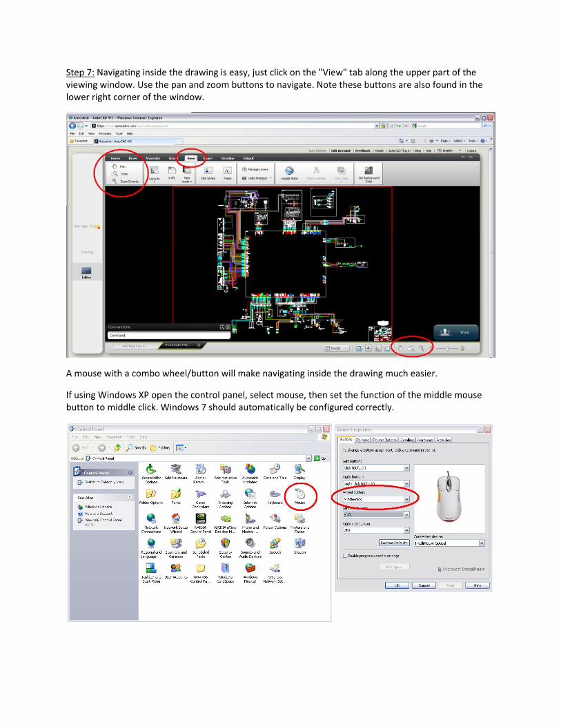
Step 7: Navigating inside the drawing is easy, just click on the "View" tab along the upper part of the viewing window. Use the pan and zoom buttons to navigate. Note these buttons are also found in the lower right corner of the window.
A mouse with a combo wheel/button will make navigating inside the drawing much easier.
If using Windows XP open the control panel, select mouse, then set the function of the middle mouse button to middle click. Windows 7 should automatically be configured correctly.

Middle Mouse Button Functions:
Rolling the wheel zooms in and out
Pressing and holding the wheel as a button while moving the mouse will "pan", move the drawing up, down, left or right.
Left Mouse Button Functions:
Single left‐click selects an object. This is helpful when trying to follow a wire through the drawing.
If the cursor is not on an object single left‐click then moving the mouse to the right creates a "selection box". Left‐click again and everything inside the "selection box" will be selected. If you accidentally create a selection box press esc to cancel out of the selection box process.
Left‐click then moving the mouse to the left creates a "crossing box". Left click again and anything touched by the "crossing box" will be selected.
Double left‐click edits an object such as text.
Step 8: Turning Items On and Off
NOTE: The layers turned on within the file "RV‐12 ELECTRICAL SYSTEM (Finish Kit Shipped prior to 08‐25‐11) MM‐DD‐YY.dwg" representing a finish kit shipped prior to 08‐25‐11 (a kit requiring the use of update harnesses) do not support turning on‐off sub‐items such as lighting, ELT, autopilot etc. If your kit does not have these items simply select then press delete to remove the items not used on your aircraft.
The control module is focused in the center of the drawing. Connecting to the control module are the harnesses that attach to the top of the control module. Within these harnesses are optional kits.
Each of these harnesses and optional kits are kept on layers that may be turned on or off.
In the following example we will assume your aircraft does not have the optional autopilot kit. We would like our drawing to reflect this. We need to turn off the layer corresponding to the autopilot. Note in the depiction below the autopilot harness and autopilot servos are visible.

Make sure you are using the "Home" tab along the top of the window. In the upper center click on the icon labeled "Manage Layers" (Note this may on some browsers be a sub menu under a button in the same location). This will bring up the layer properties manager.
Under "Name" find "Autopilot Dynon SV...". Immediately to the right is a depiction of a light bulb. When the light bulb is yellow the layer is turned on and visible.
Click in the center of the light bulb depiction to turn it grey and turn off the autopilot layer. Click on the "x" in the upper right corner of the layer properties manager to save changes and exit the manager.
Note that the autopilot harness and servos are no longer visible.
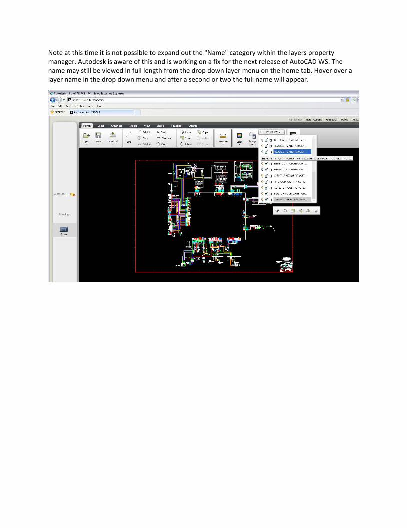
Note at this time it is not possible to expand out the "Name" category within the layers property manager. Autodesk is aware of this and is working on a fix for the next release of AutoCAD WS. The name may still be viewed in full length from the drop down layer menu on the home tab. Hover over a layer name in the drop down menu and after a second or two the full name will appear.

When an item is selected by left clicking the layer on which that item is kept is shown to the right of the "Manage Layers" icon. Note in the example below the nav strobe has been selected and the layer displayed is "Land Light..."
NOTE: Layer Names are in the following format:
Connection Name, Manufacture, Model, Harness, Aircraft
It is important check that the harness number corresponds to those used on your aircraft.

Step 9: Pan down to the lower right corner of the drawing.
Fill in all the areas of the title block. To edit text within the title block double left‐click on the text and an editing window will appear.
Fill out the title block to represent your aircraft information.
Step 10: You may want to print the file.
Under the "Output" tab select the "Plot" icon
Under the "Plot" menu that appears under "Plot Style" select "None"
Under "Plot To" select "PDF"
Under "Paper Size" select "ARCH E (36.00 X 48.00 Inches)" Note this is also the size paper you would use if printing this document at a local printing company.
Click "Ok". It will take some time to print as this is a large file but eventually a window will pop up with a "Download" button. Click Download and save the file to a specific location.
FAQ:
Q: How do I know what pins are connected within the control module?
A: Pins that are connected use the same pin nomenclature. For example "EFIS POWER 1" which is pin 13 on the "SWITCH" module connection is connected to "EFIS POWER 1", pin 17 on the "EFIS" connector.
Q: How do I print only part of the drawing to 11 x 17 or 8 1/2 x 11 format on a small printer?
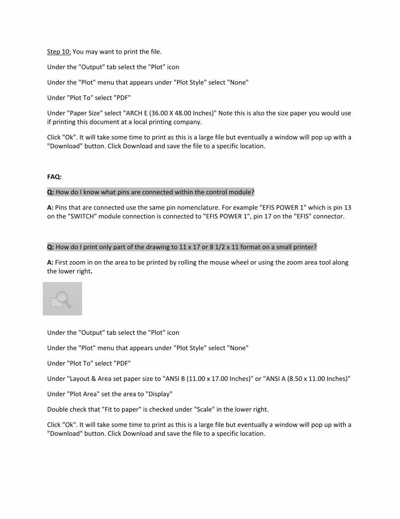
A: First zoom in on the area to be printed by rolling the mouse wheel or using the zoom area tool along the lower right.
Under the "Output" tab select the "Plot" icon
Under the "Plot" menu that appears under "Plot Style" select "None"
Under "Plot To" select "PDF"
Under "Layout & Area set paper size to "ANSI B (11.00 x 17.00 Inches)" or "ANSI A (8.50 x 11.00 Inches)"
Under "Plot Area" set the area to "Display"
Double check that "Fit to paper" is checked under "Scale" in the lower right.
Click "Ok". It will take some time to print as this is a large file but eventually a window will pop up with a "Download" button. Click Download and save the file to a specific location.
