russell porter - astrosurf · 1 russell porter (1871-1949) and the glass giant of palomar pedro rÉ...
TRANSCRIPT
1
RUSSELL PORTER (1871-1949) AND THE GLASS
GIANT OF PALOMAR PEDRO RÉ http://www.astrosurf.com/re
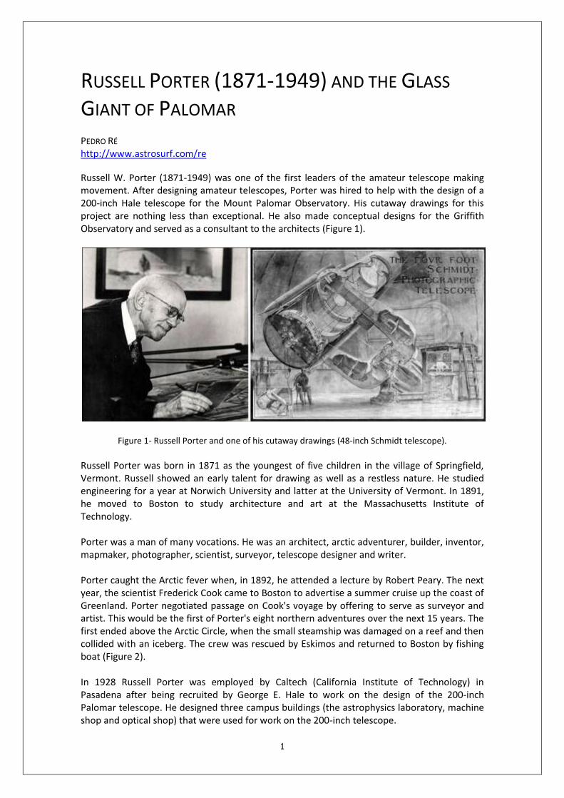
Russell W. Porter (1871-1949) was one of the first leaders of the amateur telescope making movement. After designing amateur telescopes, Porter was hired to help with the design of a 200-inch Hale telescope for the Mount Palomar Observatory. His cutaway drawings for this project are nothing less than exceptional. He also made conceptual designs for the Griffith Observatory and served as a consultant to the architects (Figure 1).
Figure 1- Russell Porter and one of his cutaway drawings (48-inch Schmidt telescope).
Russell Porter was born in 1871 as the youngest of five children in the village of Springfield, Vermont. Russell showed an early talent for drawing as well as a restless nature. He studied engineering for a year at Norwich University and latter at the University of Vermont. In 1891, he moved to Boston to study architecture and art at the Massachusetts Institute of Technology. Porter was a man of many vocations. He was an architect, arctic adventurer, builder, inventor, mapmaker, photographer, scientist, surveyor, telescope designer and writer. Porter caught the Arctic fever when, in 1892, he attended a lecture by Robert Peary. The next year, the scientist Frederick Cook came to Boston to advertise a summer cruise up the coast of Greenland. Porter negotiated passage on Cook's voyage by offering to serve as surveyor and artist. This would be the first of Porter's eight northern adventures over the next 15 years. The first ended above the Arctic Circle, when the small steamship was damaged on a reef and then collided with an iceberg. The crew was rescued by Eskimos and returned to Boston by fishing boat (Figure 2). In 1928 Russell Porter was employed by Caltech (California Institute of Technology) in Pasadena after being recruited by George E. Hale to work on the design of the 200-inch Palomar telescope. He designed three campus buildings (the astrophysics laboratory, machine shop and optical shop) that were used for work on the 200-inch telescope.

2
While working on the design of the Palomar telescope, Porter perfected his "cutaway" drawing technique. During the Second World War he assisted in the war effort by designing and drawing military hardware. He was dubbed the "Cutaway Man" by Pentagon officials for his ability to draw the internal workings of complex machinery by cutting through the outer "skin".
Figure 2- Arctic Sketches of Russell W. Porter.
Throughout his later years he was closely involved with the Stellafane Amateur Telescope-Makers movement in his hometown of Springfield, Vermont. The Stellafane Observatory stands at an elevation of about 1270 feet on an exposed shoulder of a hill about one-quarter mile southeast of the Breezy Hill Road in Springfield, Vermont. The observatory complex consists of two buildings designed by Russell W. Porter: the clubhouse of the Springfield Telescope Makers, Inc., and the observatory containing a 16-inch, reflecting turret telescope also designed by Porter (Figure 3). In 1949, while working on his last telescope project, Porter dies of a heart attack at the age of 77.
Figure 3- Stellafane turret telescope built by Russell W. Porter.
Russell W. Porter's colleague at Caltech, James S. Fassero, wrote the following introduction in his 1947 book of Porter's cutaway drawings which is entitled "Photographic Giants of Palomar": "Dr. Russell W. Porter made this unique collection of drawings over a period of 12 years using his ability to faithfully portray mechanical objects in perspective. With pencil and paper he was able to "cut away" sections of the telescope to show the inside details; something which cannot be done with a camera. His artistic and mechanical abilities have combined to produce a set of
3
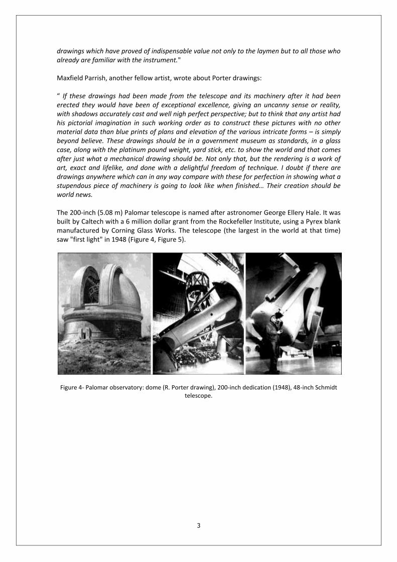
drawings which have proved of indispensable value not only to the laymen but to all those who already are familiar with the instrument." Maxfield Parrish, another fellow artist, wrote about Porter drawings: “ If these drawings had been made from the telescope and its machinery after it had been erected they would have been of exceptional excellence, giving an uncanny sense or reality, with shadows accurately cast and well nigh perfect perspective; but to think that any artist had his pictorial imagination in such working order as to construct these pictures with no other material data than blue prints of plans and elevation of the various intricate forms – is simply beyond believe. These drawings should be in a government museum as standards, in a glass case, along with the platinum pound weight, yard stick, etc. to show the world and that comes after just what a mechanical drawing should be. Not only that, but the rendering is a work of art, exact and lifelike, and done with a delightful freedom of technique. I doubt if there are drawings anywhere which can in any way compare with these for perfection in showing what a stupendous piece of machinery is going to look like when finished… Their creation should be world news. The 200-inch (5.08 m) Palomar telescope is named after astronomer George Ellery Hale. It was built by Caltech with a 6 million dollar grant from the Rockefeller Institute, using a Pyrex blank manufactured by Corning Glass Works. The telescope (the largest in the world at that time) saw "first light" in 1948 (Figure 4, Figure 5).
Figure 4- Palomar observatory: dome (R. Porter drawing), 200-inch dedication (1948), 48-inch Schmidt telescope.

4
Figure 5- Palomar observatory.
5
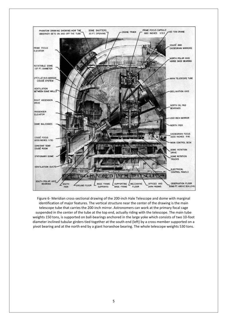
Figure 6- Meridian cross-sectional drawing of the 200-inch Hale Telescope and dome with marginal identification of major features. The vertical structure near the center of the drawing is the main telescope tube that carries the 200-inch mirror. Astronomers can work at the primary focal cage
suspended in the center of the tube at the top end, actually riding with the telescope. The main tube weights 150 tons, is supported on ball-bearings anchored in the large yoke which consists of two 10-foot diameter inclined tubular girders tied together at the south end (left) by a cross member supported on a pivot bearing and at the north end by a giant horseshoe bearing. The whole telescope weights 530 tons.
6
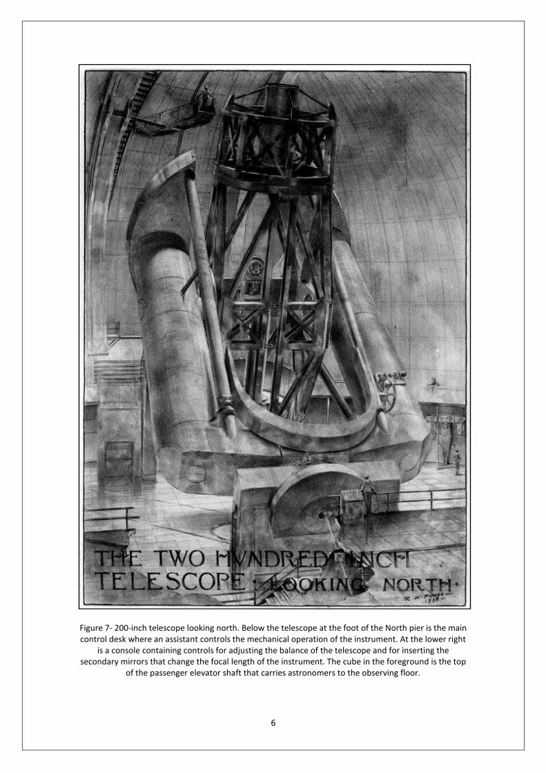
Figure 7- 200-inch telescope looking north. Below the telescope at the foot of the North pier is the main control desk where an assistant controls the mechanical operation of the instrument. At the lower right
is a console containing controls for adjusting the balance of the telescope and for inserting the secondary mirrors that change the focal length of the instrument. The cube in the foreground is the top
of the passenger elevator shaft that carries astronomers to the observing floor.

7
Figure 8- Observing in the prime-focus capsule. As astronomer is shown seated in the adjustable chair with the photographic plate holder locked to the pedestal, and his eye at the guiding eyepiece.
Exposures range from a few minutes to several hours. The astronomer’s seat can travel completely around the capsule and tilt through a large angle to compensate for any position to which the telescope
may be tipped. Dials on the wall above the astronomer’s head tell him exactly where the telescope is aimed, and switches below allow him to activate essential equipment. The plate-holder can be changed
for a spectrograph or a photoelectric photometer.
8
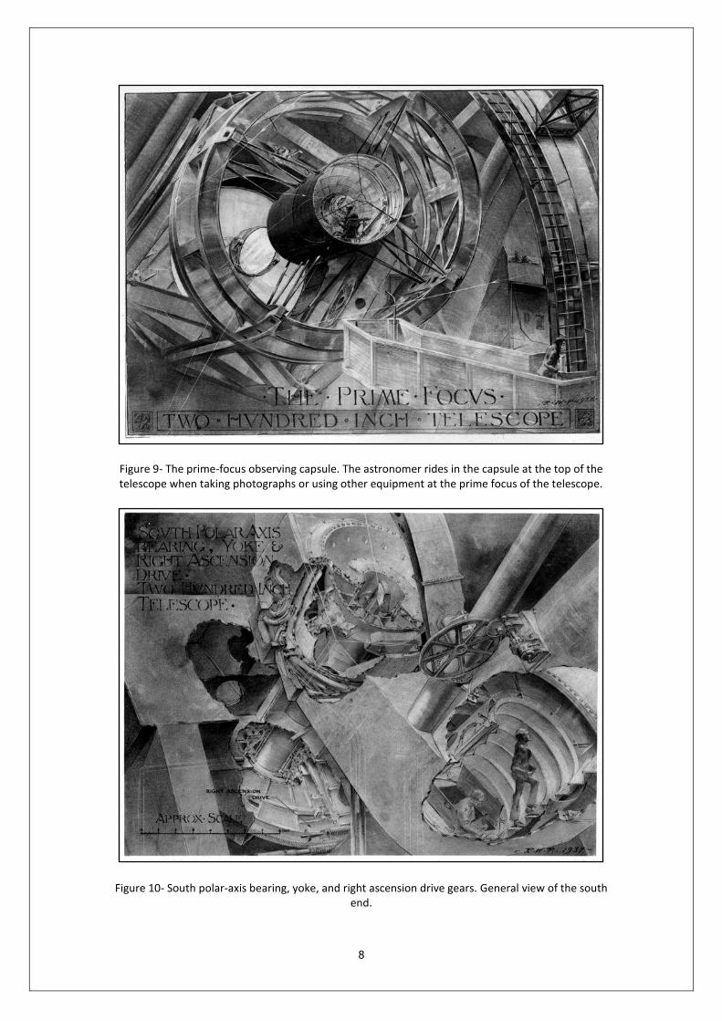
Figure 9- The prime-focus observing capsule. The astronomer rides in the capsule at the top of the telescope when taking photographs or using other equipment at the prime focus of the telescope.
Figure 10- South polar-axis bearing, yoke, and right ascension drive gears. General view of the south end.
9
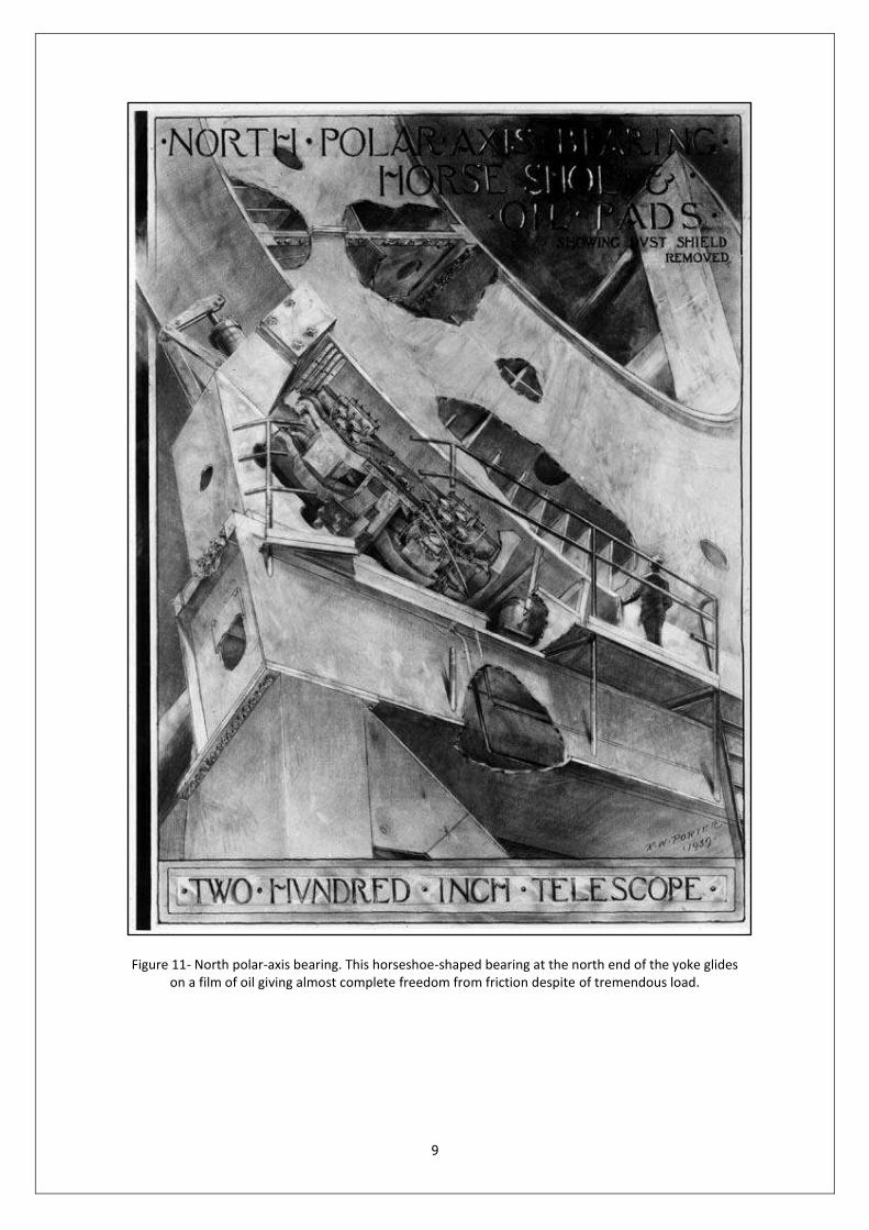
Figure 11- North polar-axis bearing. This horseshoe-shaped bearing at the north end of the yoke glides on a film of oil giving almost complete freedom from friction despite of tremendous load.
10
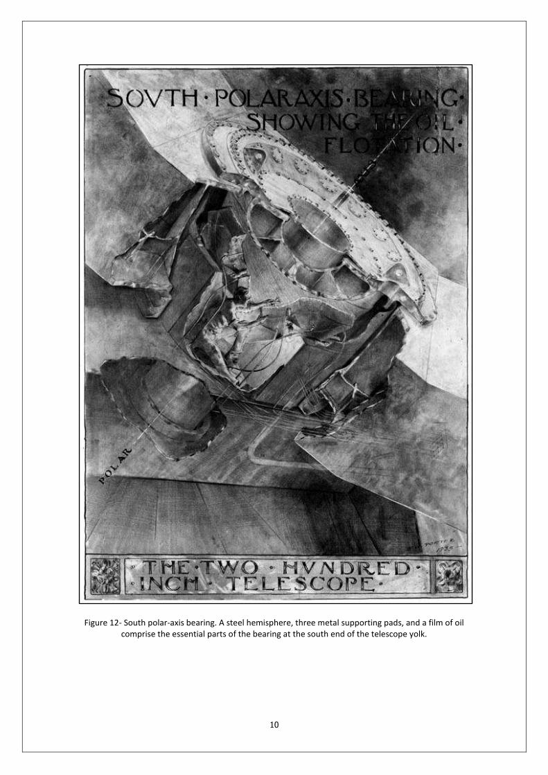
Figure 12- South polar-axis bearing. A steel hemisphere, three metal supporting pads, and a film of oil comprise the essential parts of the bearing at the south end of the telescope yolk.

11
Figure 13- West declination Trunnion. One of the two bearings that support the telescope tube.
12
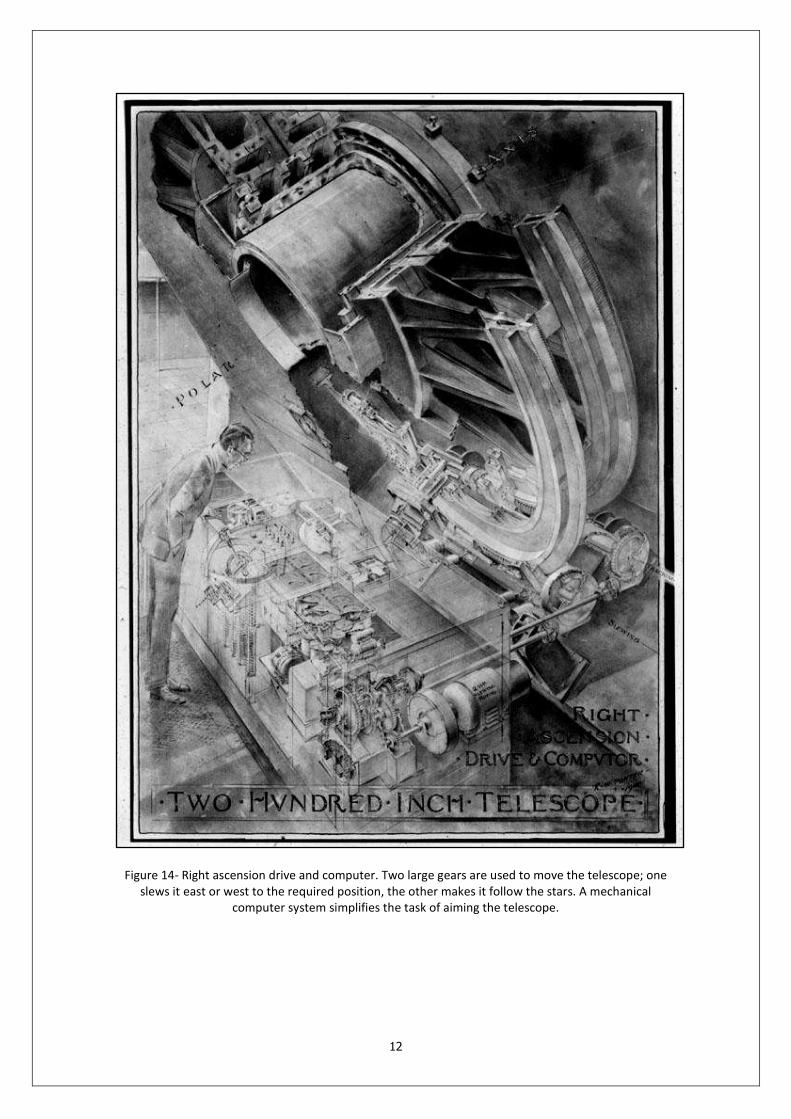
Figure 14- Right ascension drive and computer. Two large gears are used to move the telescope; one slews it east or west to the required position, the other makes it follow the stars. A mechanical
computer system simplifies the task of aiming the telescope.
13
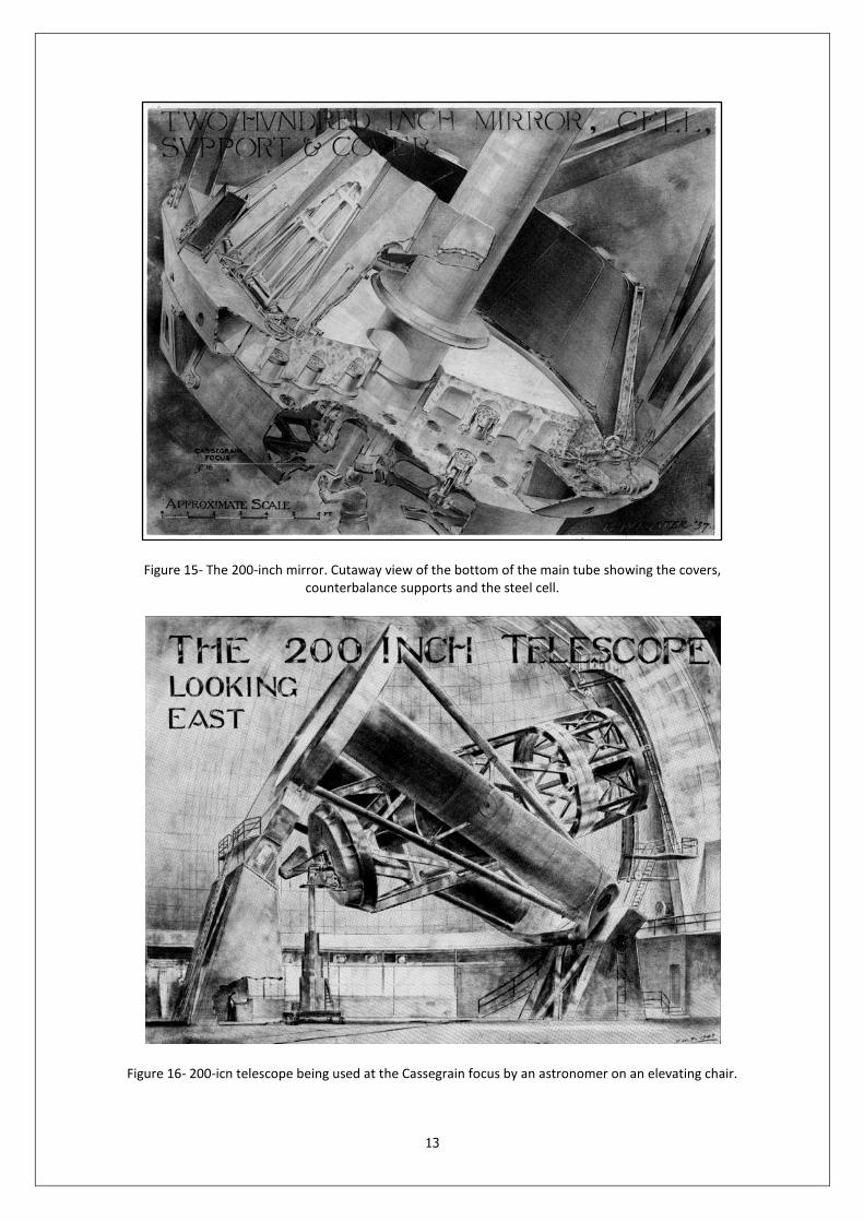
Figure 15- The 200-inch mirror. Cutaway view of the bottom of the main tube showing the covers, counterbalance supports and the steel cell.
Figure 16- 200-icn telescope being used at the Cassegrain focus by an astronomer on an elevating chair.
14
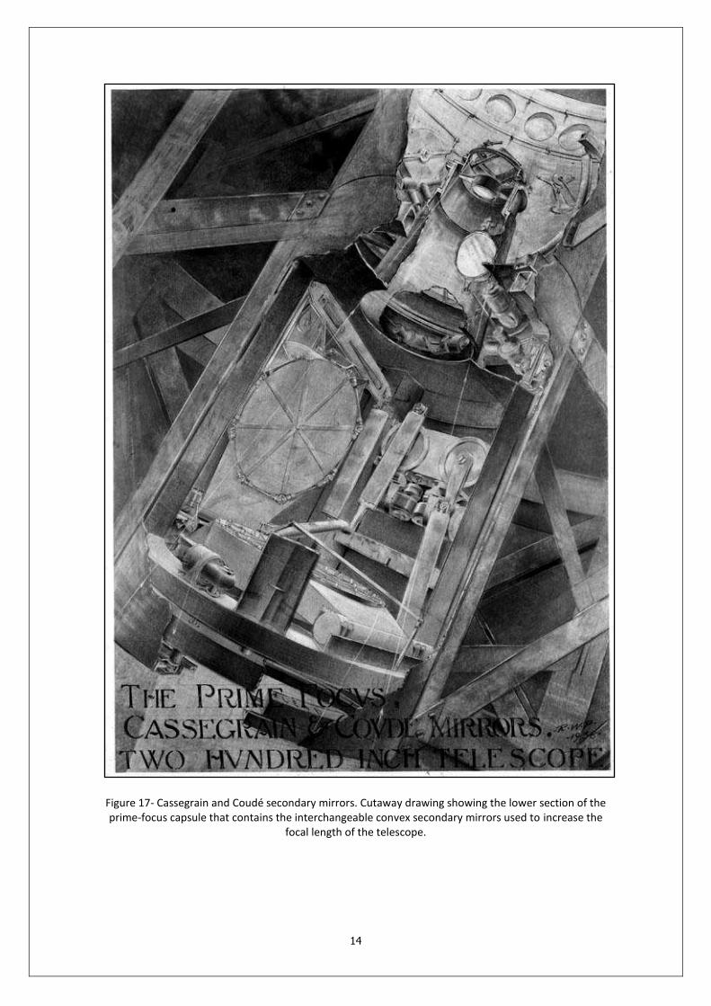
Figure 17- Cassegrain and Coudé secondary mirrors. Cutaway drawing showing the lower section of the prime-focus capsule that contains the interchangeable convex secondary mirrors used to increase the
focal length of the telescope.
15
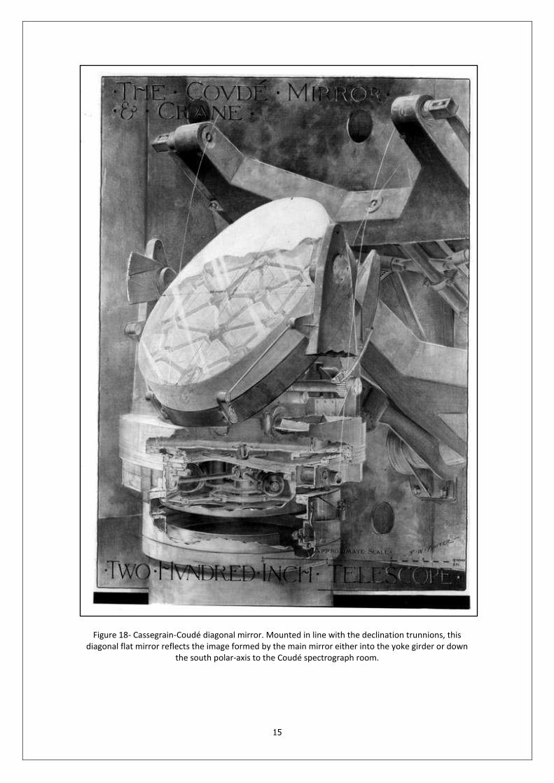
Figure 18- Cassegrain-Coudé diagonal mirror. Mounted in line with the declination trunnions, this diagonal flat mirror reflects the image formed by the main mirror either into the yoke girder or down
the south polar-axis to the Coudé spectrograph room.

16
Figure 19- Mirror counterbalance supports. Thirty-six of these intricate double-acting counterbalance devices support the 200-inch mirror at its center of gravity to prevent distortions of the huge disk when
it is tilted in different directions.

17
Figure 20- The Coudé spectrograph room containing four spectrograph mirrors of different focal lengths.
Figure 21- 48-inch Schmidt telescope (corrector plate 48-inch, main mirror 72-inch).
18
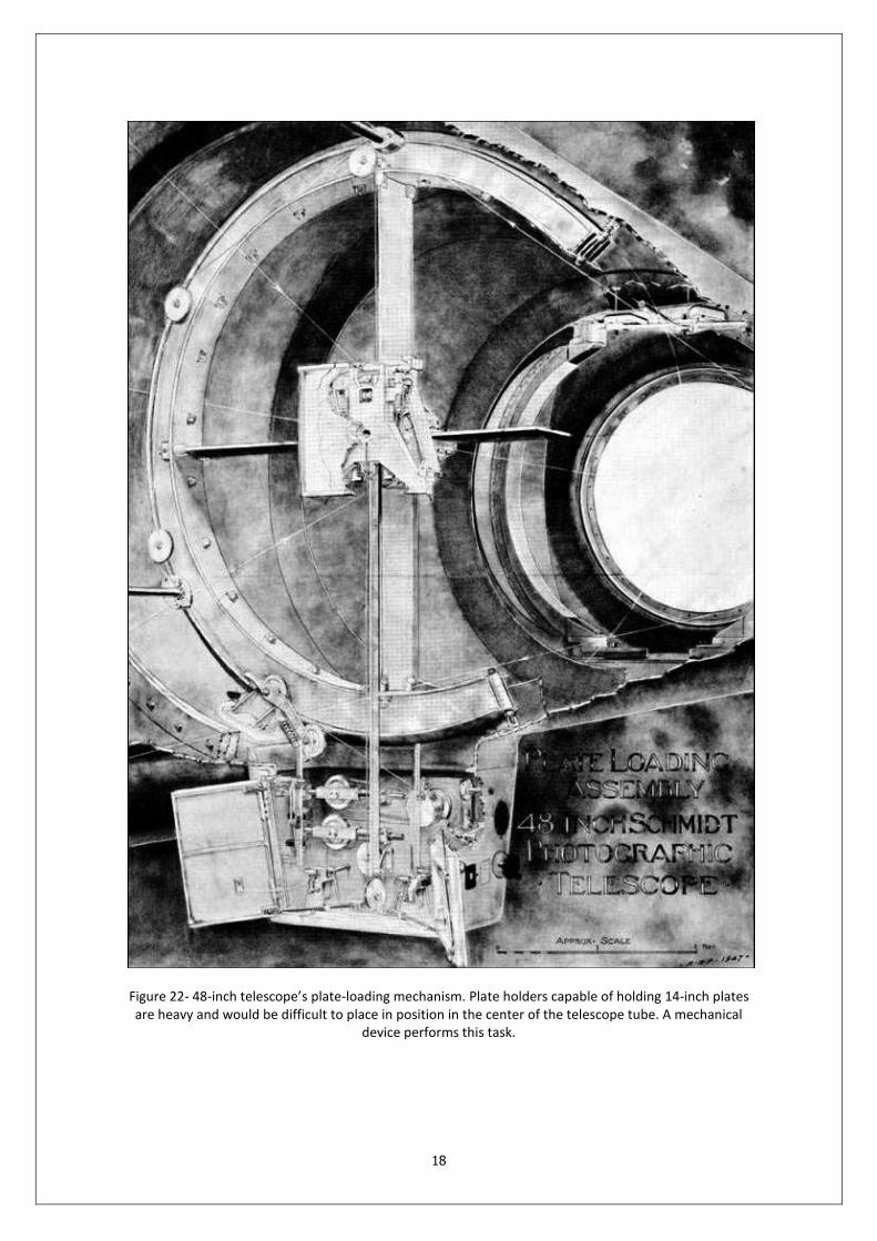
Figure 22- 48-inch telescope’s plate-loading mechanism. Plate holders capable of holding 14-inch plates are heavy and would be difficult to place in position in the center of the telescope tube. A mechanical
device performs this task.
19
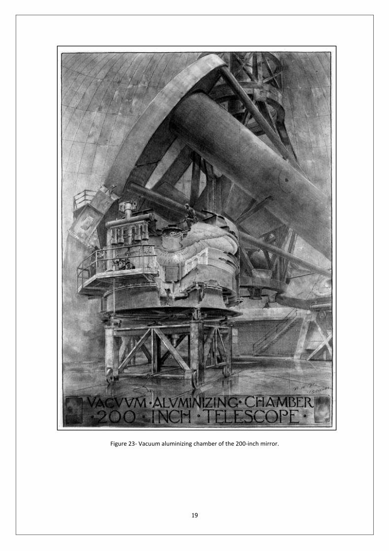
Figure 23- Vacuum aluminizing chamber of the 200-inch mirror.