rural electrification with the shield wire scheme applications in
TRANSCRIPT

RURAL ELECTRIFICATION WITH THE SHIELD WIRE
SCHEME APPLICATIONS IN
DEVELOPING COUNTRIES
by F. ILICETO University of Rome “La Sapienza”
Rome, Italy
AEI – AFRICA ELECTRIFICATION INITIATIVE WORKSHOP IN DAKAR, NOV. 2011
1

• Low cost power supply from the interconnected grid to villages, small towns, farms, factories, water pumping stations located near or at some distance from the route of the HV lines (110-330kV)
• The SWSs consist of: - Insulating for MV operation (20-34.5kV) the shield wire(s) from the towers of the HV line - Energising the shield wire(s) at MV from the HV/MV transformer station at one end of the HV line
1. AIM OF SHIELD WIRE SCHEME (SWS)
AEI – AFRICA ELECTRIFICATION INITIATIVE WORKSHOP IN DAKAR, NOV. 2011
2

- Using the earth return of current - Supplying the loads by means of distribution transformers branched between the shield wire(s) and the ground. • The most used SWSs are shown in Figs. 1/A - 1/B. • If the HV line is protected by one shield wire, only
the Single-Phase Earth-Return SWS can be realised (Fig. 1/A)
• If the HV line is protected by 2 shield wires, by using the earth return as the 3rd phase conductor, a 3-phase MV line is realised (Fig. 1/B).
2. CONCEPT OF SWSs AEI – AFRICA ELECTRIFICATION INITIATIVE WORKSHOP IN DAKAR, NOV. 2011
3

Fig.1/A - “Single-phase Earth-return” SWS applicable to HV lines provided with one shield wire
4

Fig.1/B - “3-Phase” SWS applicable to HV lines provided with two shield wires
5
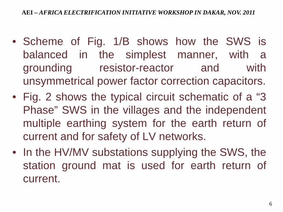
• Scheme of Fig. 1/B shows how the SWS is balanced in the simplest manner, with a grounding resistor-reactor and with unsymmetrical power factor correction capacitors.
• Fig. 2 shows the typical circuit schematic of a “3 Phase” SWS in the villages and the independent multiple earthing system for the earth return of current and for safety of LV networks.
• In the HV/MV substations supplying the SWS, the station ground mat is used for earth return of current.
AEI – AFRICA ELECTRIFICATION INITIATIVE WORKSHOP IN DAKAR, NOV. 2011
6

Fig. 2 – Circuit schematic of “3-Phase” SWS distribution in the villages, showing independent earthing of MV and LV networks 7

• The insulation of shield wires does not worsen the
lightning performance of the HV line. Fig. 3 shows the rigid insulator strings usually
applied for insulation of shield wires. • The voltage imbalance at supply points of all the
consumers of “3-Phase” SWSs (Fig.1-B) and at the busbars supplying Single-Phase Earth-Return SWSs (Fig. 1/A) is limited to a very small value (negative-sequence voltage ≤1%).
3. MAIN FEATURES OF SWSs AEI – AFRICA ELECTRIFICATION INITIATIVE WORKSHOP IN DAKAR, NOV. 2011
8
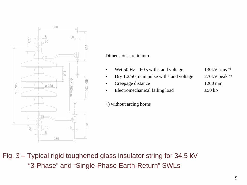
Fig. 3 – Typical rigid toughened glass insulator string for 34.5 kV “3-Phase” and “Single-Phase Earth-Return” SWLs
Dimensions are in mm • Wet 50 Hz – 60 s withstand voltage 130kV rms +) • Dry 1.2/50 µs impulse withstand voltage 270kV peak +) • Creepage distance 1200 mm • Electromechanical failing load ≥50 kN
+) without arcing horns
9

• In the new HV lines, the SWSs use ACSR shield wires, with cross section of 70÷125 sqmm. A suitable cable has 19 wires with 63% of aluminium in the cross-section.
Some SWSs have been implemented in existing HV lines, by insulating their steel or alumoweld shield wire(s).
• The reach of SWSs with rated voltage of 34,5kV is up to and also over 100 km.
AEI – AFRICA ELECTRIFICATION INITIATIVE WORKSHOP IN DAKAR, NOV. 2011
10

• The “3-Phase” SWSs have about the same loading capability of a normal MV overhead line with the same phase-to-phase rated MV and same conductors: capability is several MW at 34,5kV. Typical loading capabilities are shown in Fig. 4.
• Earth-return of current has been used for several decades in the single-wire rural electrification in some countries.
AEI – AFRICA ELECTRIFICATION INITIATIVE WORKSHOP IN DAKAR, NOV. 2011
11

+) load p.f. on LV side of MV/LV transformers; ––––– Distributed load; – – – Concentrated load Fig. 4 – Loading capability versus length of “3-Phase” SWLs operated at 34.5kV: a.1–a.2: ACSR, S=125.1 sqmm shield wires on a 230kV-60Hz line b.1–b.2: ACSR, S=76.9 sqmm shield wires on a 161kV-50Hz line
0
2
46
8
10
12
14
16
0 25 50 75 100 125 150d [km]
∆V=7.5%
P [MW]
cosΦ = 0.9
cos = 0.97Φ
60 Hz - ACSR- 125.1 sqmm
a.2)+)
+)
0
2
4
6
8
10
12
14
16
0 25 50 75 100 125 150d [km]
P [MW]
∆ V=10%
cos Φ
cosΦ
=0.9
=0.97
60 Hz - ACSR - 125.1 sqmm
a.1)
+)
+)
0 20 40 60 80 100 120 1400
2
4
6
8
10
12
∆ V=10%
cosΦ =0.97
cosΦ =0.9
P [MW]
d[km]
50 Hz - ACSR - 76.9 sqmm
b.1)+)
+)
0 20 40 60 80 100 120 1400
2
4
6
8
10
12
∆ V=7.5%
cos Φ =0.97
cosΦ=0.9
d [km]
P [MW]
50 Hz - ACSR - 76,9 sqmm
b.2)+)
+)
12
• Earth is an ideal conductor in developing countries:
- It has a small cost (cost of grounding rods and conductors installed by local manpower, used in common for other purposes) - Losses are very small (at 50Hz it is equivalent to an aluminium cable of 570sqmm) - Unlike conventional insulated conductors, it is neither exposed to insulation failure nor to interruption (“broken wire”) - Maintenance is negligible.
AEI – AFRICA ELECTRIFICATION INITIATIVE WORKSHOP IN DAKAR, NOV. 2011
13

• Design criteria and constraints of “3-Phase”
SWSs are the same as the ones for conventional MV lines, with the additional requirement of limiting the negative-sequence voltage.
• The analysis of SWSs is somewhat complex, due to interaction with HV circuit, earth-return of current and voltage balancing needs.
Operation is however simple and reliable because only conventional distribution equipment are applied, devoid of power electronic devices and using ordinary operational methods.
AEI – AFRICA ELECTRIFICATION INITIATIVE WORKSHOP IN DAKAR, NOV. 2011
14

• Although in the “3-Phase” SWSs the phase-to-ground operating voltage is higher by a factor of √3=1.732 in comparison with the conventional lines, the required increase of equipment insulation is only 15-20% above the standard of the MV equipment.
• SWLs are part of the HV line and therefore do not require specific maintenance, since it is performed for the HV line.
• No permanent faults have occurred on the SWLs lines, part of which have been in operation for over 20 years.
AEI – AFRICA ELECTRIFICATION INITIATIVE WORKSHOP IN DAKAR, NOV. 2011
15

• No permanent faults have occurred on the SWLs lines,part of which have been in operation for over 20 years.
• The outage rate due to transient faults has been reported lower for SWLs than for equivalent overhead MV lines.
• The cost of making electricity available at MV with the SWSs to communities located along the HV lines is only 10-15% of the cost of conventional solutions.
AEI – AFRICA ELECTRIFICATION INITIATIVE WORKSHOP IN DAKAR, NOV. 2011
16

• If an optical ground wire (OPGW) is applied in the HV line for telecommunications, the SWS can be realised as well by insulating for MV a standard OPGW.
• SWLs are a deterrent to vandalism and theft of HV lines, because the communities along the line must protect the line to ensure power supply to themselves from the SWL.
AEI – AFRICA ELECTRIFICATION INITIATIVE WORKSHOP IN DAKAR, NOV. 2011
17

• Ghana: About 1000km of 161kV–50Hz lines with insulated shield wires, most of which have been in operation for over 20 years (Fig. 5).
• Brasil: “3-Phase” SWSs have been in operation since 1995 at 34.5kV in a long 230kV-60Hz line.
• Laos: “Single-Phase Earth-Return” SWSs are in operation since 1996 in 190 km of 115kV-50Hz lines. “3-Phase” 34.5kV SWSs are in operation since 2002-2003 on 335km of 115 kV lines (Fig. 6).
4. SWSs in operation
AEI – AFRICA ELECTRIFICATION INITIATIVE WORKSHOP IN DAKAR, NOV. 2011
18

Fig. 5 - Single-line diagram of some insulated SWSs in Ghana (year 1989)
19

Fig. 6 - Single-line diagrams of 34.5 kV “3-Phase” SWSs in Laos (year 2002)
Total length of 34.5kV lateral lines:4.7km
Length of SWL: 25.6km Forecast load of SWL in year 2018: 790kW
Total length of 34.5kV lateral lines:3.3km
Forecast load of SWL in year 2018: 1500kW
[kW]Loads
23
67.1
511
3
Xiang Ngeun SS
Muang Cha
(Initial stage)+1x452kVAR
2x333kVAR
22kV ( Initial stage )
( Initial stage )
[kW]
Distance
Loads
[Km]N° of node
2x60kVAR
2
4.27
120
188
Length of SWL: 74.6km; total length of 34.5kV lateral lines: 21.6km
E34.5kV
0+j0
0
015
0
1
115kVBan Don SS
Non Hai SS115kV
D
0
34.5kV
22kV
0.00
1.58
0
22kV
0.0
40.6
12
66Future 34.5kV lateral line
Houay Deua
2x125kVAR
Forecast load of SWL in year 2018: 3605kW
32.3
9
30.3
928
.81
22.2
9
17.7
320
.25
12.5
7
[Km]
[kW]
5
120
120
3 4
75
6
150
7
188
120
8 9 10
75
N° of node
Loads
120
11
75
12
23.2
120
32 41
+1x115kVAR
9.58
7.82
5.12
33 7648 76End of SWL
10.3
17.6
16.5
20.5
8 10680 40
Distance
48 22 38 34
31.1
32.1
25.6
528
.67
34.1
9
37.6
11
Length of SWL: 32.4km
(Initial stage)+1x145kVAR
13 14
62 56
Na Am
44.6
47.1
Length of SWL: 76km; total length of 34.5kV lateral lines:19.6km
Length of SWL: 104.4km; total length of 34.5kV lateral lines: 54.2km
4.00
75
+1x225kVAR
N° of node [Km]
[kW]
0.00
115kVXaignabouli SS
C
B
22kV
34.5kV
13.5
00
0.00
34.5kV
19
0
0
115kV
Xieng Khuang SS
115kVNam Leuk SS
A
0
2x170kVAR
22kV
13.6
22kV
34.5kV
0.00
0
[Km]Distance
2x170kVAR
2x200kVAR
Loads
N° of node
[kW]
Forecast load of SWL in year 2018: 3100kW
Forecast load of SWL in year 2018: 5080kW
Muang Cha SS
28.7
48.9
28.1
25.0
45.1
22.0
20.9
19.7
1
[kW]
75
3x333 kVAR
350
11.3
318
8
42 31
120
12075
7.27
9.70
9.26
65
120
17.5
7
Loads 6575
1 2
80
3 4
Distance
N° of node7
Loads
300
1200
[Km]
98
75
28.7
4
32.1
6
(Final stage)
5
75
6
75
7
( Initial stage )
27.1
6
11
12880 808040 119
160 40 80 4080
Distance
15.2
716
.98
10.0
46.
93
12.6
7
21 3 54
24.2
9
19.3
9
21.6
920
.51
876 9 10
128
24080 40 8080 128
37.9
1
17
31.7
4
29.1
528
.12
141213 1615
39.9
2
18
64.1
76.0
60.4
62.1
22kV
11
+1x334kVAR
12
41.6
0
1110
120 75 75
38.4
740
.40
151413
3875 7546
.57
45.3
0
48.4
3
150
10
15035
8 9
3950
19
59.6
738
1716
7575
53.9
1
51.2
8
2120 22
7538 120
61.3
560
.93
64.8
7
14+j4
( Final stage )
80 256 804040
+1x225kVAR
61.1
1
20
55.9
3
19
68.3
9
63.3
466
.41
2221 23
80280 80208
80
40128
83.2
9
25
77.3
9
24
89.1
291
.08
26 27
3x200kVAR( Final stage )
28
73.8
675
26272524
3876 387570
.43
69.1
1
73.7
172
.12
29
3874
.60
N°
of n
ode
121.3529
[K
m]
129.28
123.28
3130
Dis
tanc
e
104.
40
28
20

• Sierra Leone: “3-Phase” SWSs (Un=34.5kV) are in operation in 150km of 161kV-50Hz lines (Fig. 7).
• Ethiopia: “Single-Phase Earth-Return” SWSs (Un=34.5 kV) are in operation on 200 km of 132kV-50Hz lines (Fig. 8).
• Togo: “3-Phase” SWSs (Un=34.5kV) are in operation in 265km of 161kV-50Hz lines. One of the shield wires is an insulated OPGW (Fig.9).
• Burkina Faso: “3-Phase” 34.5 kV SWSs are in operation in 330 km of 225kV-50Hz lines. One insulated shield wire is an OPGW (Fig.10).
AEI – AFRICA ELECTRIFICATION INITIATIVE WORKSHOP IN DAKAR, NOV. 2011
21

Fig. 7 - Single-line diagram of 34.5 kV “3-Phase” SWSs in Sierra Leone
22

Fig. 8- Single-line diagrams of 34.5 kV “Single-Phase Earth-Return” SWSs in Ethiopia (year 2000)
132 kV-115.7 km132/15 kV
132 kV-84.7 km
GHIMBI S/S NEKEMPTE S/SGHEDO S/S
34.5 kV
Sire
230 kV230/132/15 kV22/22/5.5 MVAtwo units
132/15 kV25 MVA15 kV
25 MVA
IT ITIT: 15kV/34.5kV+2x3.75%-3 MVA
15 kV
15 kVIT
84.3
1299
35 32.5 31.4 8 km
487 133 1155 100Loads
kW
km 42.7
2180125250179
15 18 28
936 325
60 50
34.5 kV LoadskW
34.5 kV
300 kVAR 300 kVAR 300 kVAR
0 0 73 km 0
Sum of simultaneous peak loads of SWLs in year 2019 =2734 +1987=4721 kWTotal length of SWLs=42.7+73=115.7km
Sum of simultaneous peak
Total length of SWL=84.3 kmloads of SWL in year 2019 =3174 kW
726
132 kV
23

Fig. 9 – Single-line diagrams of 34.5kV “3-Phase” SWSs in Togo 24

Fig. 10 Single-line diagrams of 34.5kV “3-Phase” SWSs in Burkina Faso
25