running head: floor strata stratal … · turbidite, basin-floor fan, architectural element, ......
TRANSCRIPT

Running head:
FACIES AND ARCHITECTURAL ELEMENTS OF DEEP-MARINE BASIN-
FLOOR STRATA
Title:
STRATAL COMPOSITION AND COMPONENT ARCHITECTURAL
ELEMENTS OF AN ANCIENT DEEP-MARINE BASIN-FLOOR
SUCCESSION, NEOPROTEROZOIC WINDERMERE SUPERGROUP,
BRITISH COLUMBIA, CANADA
List of authors:
Viktor Terlaky1, Jonathan Rocheleau
1,2, R.William C. Arnott
1
1Department of Earth Sciences and Ottawa-Carleton Geosciences Centre,
University of Ottawa, 140 Louis Pasteur Pvt., Ottawa, ON, Canada
2NWT
Geosciences Office, Box 1500, Yellowknife, NT, Canada
e-mail: [email protected]
Key words:
Turbidite, basin-floor fan, architectural element, lobe element, depositional lobe

1
ABSTRACT
Despite a globally growing 3D seismic dataset, the detailed (cm to Dm scale) internal
sedimentology and architecture of deep-marine basin-floor “channelized-lobe” strata remain
poorly known. An exemplary analogue for modern mixed-sediment passive margin deep-marine
fans is the well-preserved deep-marine basin-floor sedimentary pile of the Neoproterozoic Upper
and Middle Kaza groups in the southern Canadian Cordillera. This several-km-thick succession
comprises six facies, which include massive coarse-grained sandstone, coarse-grained sandstone
with traction transport structures, graded sandstone with well-stratified fine-grained tops,
medium-grained matrix-rich sandstone, thin to medium-bedded siltstone and mudstone, and
mudstone-rich chaotic facies. Assemblages of one or more of these facies comprise seven
architectural elements, and include: Isolated Scours up to 5 m deep, several 100 m wide and
filled with coarse sandstone; Avulsion Splays up to several m thick, >several 100 m wide
comprising matrix-rich sandstone beds; Feeder Channels up to 15 m deep, >600 m wide and
filled with a multiply incised heterolithic succession of coarse- and fine-grained sandstone;
Distributary Channels several meters deep, up to several 100 m wide and consisting of a coarse
sandstone axial part that transitions rapidly laterally into finer, thinner-bedded turbidites;
Terminal Splays up to 10 m thick, >2 km wide and over much of their extent consist of a
laterally continuous layer of coarse sandstone that only at its margins grades rapidly to fine-
grained upper division turbidites; Distal and Off-Axis Fine-Grained Turbidites up to 35 m thick,
laterally continuous and comprise fine-grained turbidites intercalated with coarse sandstone beds;
Debrites that are up to a few Dm thick and more than 1 km wide.
Previous studies have shown that despite differences in tectonic setting or mode of sediment
supply to the basin, the overall dimensions of architectural elements remain similar. This, then,
2
provides a robust predictive tool for fans where data regarding the internal stratigraphic make up
of architectural elements is unknown. To add to this globally growing pool of knowledge it is
shown here that each architectural element comprises a representative vertical and lateral
assemblage of lithofacies, and that their dimensions are consistent with those described from
previous seismic and outcrop studies. This, then, suggests that knowing the stratal composition
of a single architectural element can be used to predict the make up of other elements within the
same fan. Moreover, the noted scalar similarity of architectural elements in this and other studies
suggests that stratigraphic data from this study can be applied to a range of mixed basin floor
systems formed in a variety of tectonic settings.
INTRODUCTION
The understanding of deep-water basin-floor “sheet-like deposits” or “channelized lobes”
has in recent years been greatly improved due to advances in 3D seismic (e.g. Normark 1978;
Piper and Normark 2001; Beaubouef et al. 2003; Posamentier and Kolla 2003; Deptuck et al.
2008; Jegou et al. 2008; Saller et al. 2008), but still modern marine seismic and core typically
lack the vertical and lateral resolution, respectively, to effectively identify and characterize
small-scale architectural elements. The majority of basin-floor studies, then, describe the
dimensions of large-scale features like basin-floor fans, lobe complexes and lobes (for a
comprehensive compilation see Prélat et al. 2010). Seismic or side-scan sonar studies that
describe the dimensions of smaller scale architectural elements that make up the sedimentary
bodies of lobes include: isolated scours by Normark et al. 1979, Kenyon and Millington 1995,
Morris et al. 1998, Wynn et al. 2002, and Deptuck et al. 2008; feeder channels by Twitchell et al.

3
1992, Wynn et al. 2002, Jegou et al. 2008 and Saller et al. 2008; distributary channels by
Normark 1978; Normark et al. 1979, Twitchell et al. 1992, Gardner et al. 1996, Piper et al. 1999,
Beaubouef et al. 2003, Deptuck et al. 2008, Jegou et al. 2008, Saller et al. 2008, and Gervais et
al. 2010; terminal splays by Piper et al. 1999, Beaubouef et al. 2003, Deptuck et al. 2008, Saller
et al. 2008 and Gervais et al. 2010. The internal sedimentology and stratigraphy of the elements
is typically determined from core, or is inferred from seismic reflections and/or backscatter
intensity only (e.g. low-intensity backscatter was inferred as distal distributary channels on the
Mississippi Fan by Twitchell et al. 1992).
Study of outcrop analogue examples remains integral to the understanding of depositional
basin-floor systems. Though many outcrops are compromised by lateral and/or vertical size
limitations, studies across a number of ancient turbidite systems have provided an ever growing
knowledge base of deep-water deposits, e.g. channels and sheet-like sand bodies of the Brushy
Canyon Formation (Beaubouef et al. 1999; Carr and Gardner 2000; Gardner and Borer 2000;
Gardner et al. 2003), channels and sheet-like sand bodies of the Punta Barrosa and Cerro Toro
formations (Fildani et al. 2007, 2009; Hubbard et al. 2008; Bernhardt et al. 2011; Romans et al.
2011), scours, channels, lobe elements (sand sheets), slumps and mudstone sheets of the Ross
Formation (Elliott 2000; Sullivan et al. 2000; Martinsen et al. 2000, 2003; Pyles 2007, 2008),
and channels and sheet-like sandstones of the Karoo Basin (Sullivan et al. 2000; Johnson et al.
2001; Sixsmith et al. 2004; Hodgson et al. 2006; Prélat et al. 2009; Groenenberg et al. 2010;
Flint et al. 2011). The purpose of this paper is to add to this ever-growing knowledge base of
basin-floor strata by providing a detailed sedimentological and stratigraphic description of the
internal make up of architectural elements that make up the deep-marine basin-floor fan system
of the Windermere Supergroup. These elements include isolated scours, avulsion splays, feeder-
4
and distributary channels, terminal splays, debrites, and off-axis fine-grained units. From this
study it is clear that, excluding debrites, all basin-floor architectural elements comprise similar
facies, but nevertheless can be differentiated by their overall cross-sectional shapes and
dimensions, and/or internal organization of facies. In order to provide a widely usable predictive
framework, then, the dimensions of the architectural elements described in this study are
compared with similar features reported in the literature and shown to be similar. This finding
supports earlier studies (Sullivan et al. 2000; Sinclair and Tomasso 2002; Pyles 2008; Pyles et al.
2011) that showed a self-similarity in depositional element size and stacking patterns across
different tectonic settings and styles of sediment input. This suggests that the reported
lithological make up and stratigraphic relationship between elements in this study add to
developing a robust predictive framework that can be used in other basin-floor fans, modern or
ancient, especially where such data are limited.
GEOLOGIC BACKGROUND OF THE WINDERMERE SUPERGROUP
The Neoproterozoic Windermere Supergroup (WSG) comprises an extensive outcrop belt
with exposures from northern Mexico to the Alaska-Yukon border (Ross et al. 1989). Deep-
marine siliciclastic rocks of the WSG crop out superbly in the southern Canadian Cordillera, and
in the Cariboo Mountains of east-central British Columbia and comprise the Kaza and Cariboo
groups (Campbell et al. 1973; Ross et al. 1995).
Rocks of the Kaza Group, and its stratigraphic correlatives, overlie a succession of
intercalated coarse-grained siliciclastic rocks of the Toby Formation and mafic volcanic rocks of
the Irene Formation (Fig. 1), which are interpreted to have been deposited during the break-up

5
and rifting of Rodinia (Aalto 1971; Ross et al. 1995). In the Cariboo Mountains the Kaza Group
consists of three stratal units (Lower, Middle and Upper) that show an upward increase in
sandstone (grit) content (Ross et al. 1995; Ross and Arnott 2007). The Middle and Upper Kaza
groups are separated by the Old Fort Point Formation (OFP), a regional stratigraphic marker that
crops out across the entire deep-marine Windermere outcrop belt, and forms an up to 150 m
thick, geochemically distinct deep-marine succession of shale with lesser carbonate and
sandstone (Fig. 1; Smith 2009; Smith et al. 2012). The Kaza Group is then conformably overlain
by the Isaac Formation (Fig. 1), which comprises shale dominated base-of-slope and continental
slope deposits intercalated with Dm-thick, sandstone filled leveed channels (Navarro et al. 2007;
Ross and Arnott 2007; Schwarz and Arnott 2007). Collectively, rocks of the Kaza and Cariboo
groups are interpreted to have been deposited in a passive margin, deep-water ocean basin, and
form a ~5 km thick upward-shoaling succession related to the basinward progradation of the
paleo-Laurentian continental margin into the paleo-Pacific miogeocline (Bell et al. 1987; Ross
1991; Ross et al. 1995; Karlstrom et al. 2001; Ross and Arnott 2007).
DATA SET AND METHODOLOGY
This study focuses on the Middle and Upper Kaza groups (Fig. 1) combining data from two
exposures (Mt.Quanstrom and Castle Creek) located in the Cariboo Mountains near McBride,
British Columbia (Fig. 2). Both exposures comprise well-exposed vertically-dipping periglacial
strata. Due to the relatively recent deglaciation of these strata overburden cover is limited to
localized glacial till and outwash, and vegetation, such as grass or lichen, is generally absent,
even on fine-grained rocks. In conjunction with the superb exposure, the vertical dip of the rocks
6
allows beds to be physically walked-out in the field, resulting in highly accurate stratigraphic
correlations and detailed documentation of lateral changes in facies, bed thickness and contacts.
Due to the two-dimensional nature of the outcrop, however, paleoflow directions are limited to a
small number of measurements that indicate transport generally toward the northwest.
At Mt. Quanstrom the Middle Kaza exposure comprises 5 outcrops that allow for correlation
of strata over more than 2 km laterally and exposes a total stratigraphic thickness of over >1 km.
Across the outcrops a total of over 2.3 km of section was logged at centimeter-scale and
triplicate gamma-ray measurements taken every 75 cm. Major lithofacies boundaries were
mapped on high-resolution aerial photographs for all outcrops. In addition, the two best
sandstone exposures (each 135 m wide and 30-35 m thick) were mapped bed-by-bed on the
aerial photos.
The Upper Kaza crops out well at Castle Creek and consists of a single ~1 km wide outcrop
with a vertical exposure of ~600 m. Most of the data discussed here were collected from the
lower ~150 m of the outcrop where a total of ~1500 m of section was measured and mapped in
detail on aerial photos. The upper ~450 m of the Upper Kaza stratigraphy was surveyed and key
attributes (facies, architectural elements and their stacking patterns) were noted and mapped. In
addition, type examples of three architectural elements were logged and mapped in detail in the
upper part of the Upper Kaza.
FACIES DESCRIPTIONS AND INTERPRETATIONS
Fieldwork investigating strata of the Middle Kaza Group at Mt. Quanstrom and the Upper
Kaza Group at Castle Creek identified six lithofacies. In addition to field-based lithological
7
descriptions, thin section analysis and gamma-ray profiles measured with a hand-held
scintillometer were used to characterize each facies. The six facies include:
1. Massive to coarse-tail graded, coarse-grained, amalgamated sandstone
2. Coarse-tail graded sandstone with traction transport structures
3. Graded sandstone beds with locally well-stratified fine-grained tops
4. Massive and coarse-tail graded, medium-grained, matrix-rich sandstone
5. Thin to medium-bedded siltstone and mudstone
6. Mud-rich chaotic facies
A summary of facies descriptions and interpretations are presented in Table 1 and
representative photographs shown in Figures 3-8. All facies, except Facies 6, are present
throughout the Kaza Group; Facies 6 is notably absent in the Middle Kaza Group. It should be
noted that these six facies are end-members, and a continuum of gradational facies between the
end-member kinds can be identified. Facies may also grade laterally into one another over
distances of several 10’s of meters to 100’s of meters through intermediate facies.
ARCHITECTURAL ELEMENTS
Definition
Architectural element analysis has been common practice since it was first introduced for
fluvial strata by Miall (1985). Since its inception the concept of architectural element analysis
has been applied successfully to submarine-fan strata and is gaining in popularity (e.g. Pickering
and Clark 1996; Carr and Gardner 2000; Gardner and Borer 2000; Sullivan et al. 2000;
8
Drinkwater and Pickering 2001; Johnson et al. 2001; Sprague et al. 2002; Hodgson et al. 2006;
Pyles 2007, 2008; Prélat et al. 2009, 2010), although due to a lack of common definition and
terminology a plethora of terms has been in use to describe the various building blocks across
various hierarchical levels of a submarine fan. In this paper the definition of architectural
element proposed by Pyles (2007) is adopted: an architectural element is defined as “a mesoscale
lithosome (>1 m [>3 ft] thick, >20 m [>66 ft] wide) characterized by its external shape in
depositional-strike view that forms the fundamental building block for larger stratigraphic units,
including parasequences, systems tracts and sequences”. This definition can be applied usefully
to this study, because it limits the size of architectural elements to mesoscale features that are
observable and mappable at outcrop scale, and also characterizes architectural elements by their
external shape in strike-view, which is the view available in the observed 2-D outcrops.
Furthermore, this definition of architectural elements is useful because it implicitly implies a
hierarchical system of elements, and can be merged seamlessly with existing basin-floor lobe
models (see Mulder and Etienne (2010) for a review and summary of recent lobe terminology,
morphology, geometry and construction). In this study we adapt the hierarchical scheme
compiled by Mulder and Etienne, where architectural elements (termed lobe elements in several
papers, e.g. Prélat et al. 2009; Mulder and Etienne 2010) comprise the sedimentary bodies of
depositional lobes, which in turn stack to form lobe complexes and ultimately the depositional
fan.
Architectural Elements in Basin-Floor Strata of the WSG

9
Seven architectural elements were identified in strata of the Upper and Middle Kaza groups.
Each architectural element (AE) comprises one or more of the previously described facies, which
vary not only between the different elements, but also spatially within an individual element (e.g.
depositional axis, or margin, proximal or distal). The elements include:
1. Isolated scour with coarse-grained sandstone fill (Isolated scours, common in the
Upper Kaza, rare in the Middle Kaza)
2. Deep scour and heterolithic channel fill (Feeder channels, two examples in the Upper
Kaza)
3. Shallow scour and heterolithic channel fill (Distributary channels, common in the
Upper Kaza)
4. Sheet-like coarse-grained sandstone (Terminal splays, common in both the Upper and
Middle Kaza)
5. Sheet-like medium-grained matrix-rich sandstone (Avulsion splays, present in both
the Upper and Middle Kaza, but more common in the Upper Kaza)
6. Sheet-like fine-grained turbidites (Distal and off-axis fine-grained turbidites,
common in both the Upper and Middle Kaza)
7. Thick-bedded chaotic units (Debrites, present only in the Upper Kaza)
Architectural Element 1: Isolated Scour with Coarse-grained Sandstone Fill
AE 1 comprises 1 to up to ~5 m deep and several 10’s to up to 300 m wide scours with
massive coarse-grained sandstone fills (Facies 1), interbedded locally with mudstone breccia and
sandstones of Facies 2 and 3. These elements are rare in the Middle Kaza, and become more

10
common stratigraphically upward in the Upper Kaza. The bases of AE 1 are irregular scours
reaching a depth of several meters over a distance of several 10’s of meters (Figs. 9, 10). In the
Upper Kaza scour bases typically truncate distributary channels and/or avulsion splays (Fig. 9),
but in the Middle Kaza terminal splays are eroded (Fig. 10). Regardless of stratigraphic setting
the fill of AE 1 shows negligible lateral or vertical facies change and sandstone beds commonly
onlap the basal scour surface. Erosion at bed bases is common within AE 1, with scours ranging
from several centimeters up to several dm deep.
AE 1 is most common in the upper part of the Upper Kaza, or more specifically, in the
most proximal part of the basin floor setting. AE 1 is interpreted to be shallow scours created by
energetic turbulence in Type C flows of Huang et al. (2009), that then were filled by later flows.
Type C flows have densiometric Froude numbers less than unity and experience energetic
hydraulic jumps at slope breaks, resulting in local, but intense erosion of the basin floor (Huang
et al. 2009). Scours with dimensions similar to those of AE 1 have been described by Wynn et al.
(2002) at the slope break (termed channel-lobe transition zone) on the modern Rhone Fan and at
the mouths of the Lisbon and Agadir canyons. These scours created local topography on the
basin floor, and subsequently were either rapidly filled with coarse sediment by bypassing flows,
or were exploited by these flows to create a continuous conduit of sediment transport, a “feeder
channel” (see AE 2).
Architectural Element 2: Deep Scour and Heterolithic Channel Fill
Two occurrences of AE 2 are exposed in the Upper Kaza Group at Castle Creek, but is
absent in strata of the Middle Kaza Group. The base is marked by a sharp and terraced erosional
11
surface exposed over the full width of the outcrop (~800 m). Erosion is up to ~15 meters deep.
The scour at the base of the lowermost occurrence deepens from the northwest towards the
southeast, whereas the surface underlying the uppermost occurrence deepens from the southeast
towards the northwest. Assuming a (semi-) symmetrical shape of the scour and an only slightly
oblique orientation to the outcrop (palaeocurrent roughly perpendicular to outcrop face), it is
evident that only part of this feature is exposed, implying that AE 2 is more than 800 m wide.
Both examples of AE 2 have a sharp, terraced basal scour surface and a multi-stage, heterolithic
fill comprising several cut and fill events. The lower channel fill is dominated by several
upward-fining units consisting of Facies 1, and 2 at the base overlain by Facies 5 near the top.
These units gradually amalgamate toward the channel axis and form a thick coarse-grained
sandstone fill. In both channels a mudclast-breccia dominated unit near the lower channel margin
is observed. The upper fill of the channel is dominated by thin-bedded, fine-grained turbidites
intercalated with coarse-grained sandstone lenses. The top of both channels is sharp and planar.
The uppermost occurrence of AE 2 is described in detail in Figure 11 and illustrates the multi-
stage history of erosion and deposition (Units 1-5) observed in this element.
Architectural Element 2 is interpreted to be a feeder channel that supplied a down-flow lobe
complex. Its overall dimensions, scour depth and width correspond well with examples described
in the literature (e.g. Twitchell et al. 1992; Johnson et al. 2001; Wynn et al. 2002; Saller et al.
2008), and its exclusive occurrence in the upper part of the Upper Kaza puts it in the most
proximal part of the basin floor. The erosion surfaces and fill of Architectural Element 2 are
interpreted to comprise three stages of channel development and fill (see Fig. 11). Stage 1
comprises the basal scour surface, interpreted to be the master scour surface that was the result of
erosion by by-pass flows feeding a down-flow lobe complex, and deposition comprising units 1
12
and 2, which are characterized by by-pass facies and abundant sediment reworking. Stage 2 is
characterized by a period of erosion and full by-pass (erosional surface 3). In this stage the upper
part of the channel is widened resulting in a terraced basal scour surface, which is probably the
result of increased flow discharge due to upstream channel maturation enhancing transport
efficiency to more distal parts of the basin floor. Hereafter the channel entered an aggradational
backfilling stage (Units 3 and 4). Stage 3 comprises Unit 5, representing gradual channel
abandonment. The upward-fining trend and decrease in the number of coarse-grained interbeds
indicates a gradual shut-down of local sediment supply rather than abrupt abandonment.
Architectural Element 3: Shallow Scour and Heterolithic Channel Fill
AE 3 comprises shallow (up to 5 m deep) channels with lithologically variable fill (Fig. 9,
12). These elements are not observed in the Middle Kaza, but are common in the Upper Kaza
and generally become more abundant stratigraphically upward as AE 4 becomes less common
(see next). Channel bases form low aspect ratio scours, reaching a maximum depth of several
meters over distances of up to several hundred meters laterally. In contrast to the deeply scoured
base of feeder channels these basal scours are commonly not terraced, but rather are smooth,
gentle sloping surfaces. Strata of AE 3 commonly abruptly overlie or are overlain by laterally
continuous sheet-like sandstones of AE 4. Units of AE 3 are typically 1 – 5 meters thick and
uncommonly up to 15 m thick. This suggests local sediment aggradation even after the shallow
channel scour was filled. Like AE 2, these channels lack recognizable levees, and in this case
pass laterally into progressively finer-grained and thinner-bedded turbidites.

13
Most channels have a sand-rich fill, although a range exists from sand-rich to more fine-
grained turbidite fills. In the thickest part of the fill, interpreted to be the depositional axis of the
channel, the basal scour surface is commonly overlain directly by sand-rich beds of Facies 1, 2
and 3 that range from decimeters up to a meter thick. Beds gradually thin and fine to Facies 5
near the top of the channel fill, forming a few to several meter-thick, upward-fining succession.
A similar facies change is observed laterally, where coarse, amalgamated sandstone beds of
Facies 1, 2 and 3 in the channel axis fine and de-amalgamate into strata of Facies 5. Beds are
typically continuous from channel axis to the channel margins and into the overbank area,
gradually thinning and fining away from the channel axis. In a small number of cases, however,
the axes of two laterally adjacent channel axes merge from opposite directions into an
intervening unit of Facies 5 strata. However, much more commonly AE 3 transitions laterally
into fine-grained strata of AE 6.
The shallow, broad basal scours of AE 3 indicate that, compared to flows that created the
basal erosional surfaces of AE 2, these features were eroded by comparatively low energy flows.
The presence of bypass facies at the channel base and axis, in addition to the lateral continuity of
beds from channel axis into the overbank area, suggest that while the high-energy cores of
depositional turbidity currents were confined to the channel axis, the currents easily and
continuously over-spilled their confinement.
Turbidity currents become unconfined down-flow of the upslope channel-levee transition
zone (Wynn et al. 2002), and as a consequence thicken and expand laterally (see Parsons et al.
2002 and Alexander et al. 2008 for flume study examples, or Hall and Ewing 2007 for a physical
examination of turbulent plane wall jets exiting channels). Experiments conducted on wall jets
have shown that flows naturally develop slow and fast moving “superstructures” that orient
14
themselves parallel to flow direction (Adrian 2010; Marusic et al. 2010). It is envisioned that the
expanding turbidity currents overrode the entire depositional lobe (Maier et al. 2011), while the
high-density core of the currents became divided and preferentially diverted through a network
of broad and shallow distributary channels that paralleled flow superstructures. Initially flows
exploited pre-existing topography, or eroded the basin floor due to increased turbulence near the
point of unconfinement (Hogg et al. 1997; Alexander et al. 2008). Later flows may have
enhanced these features and over time created a shallow distributary network. Alternatively, the
experiments of Yu et al., (2006) report that distributary channels are aggradational with
depositional levees; however the channels observed in the Upper Kaza lack levees, and have a
shallow scoured base. The aggradational nature of these channels however, albeit rare, has been
observed in the Upper Kaza. These channels have a shallow scour surface, but an aggradational
fill thicker than the channel’s depth, and have architecture similar to the ones described by Yu et
al. (2006). AE 3 is interpreted to be the fill of short-lived, shallow distributary channels formed
on the surface of a depositional lobe and transferred sediment to downstream terminal splays.
These channels were initiated by scouring at the base of flows, which also exploited pre-existing
topography. Subsequently channels became infilled, and in some cases aggradational too,
forming deposits thicker than the depth of the channel’s basal scour.
Architectural Element 4: Sheet-like Sandstone
AE 4 forms amalgamated sheet-like sandstone units 1 to up to 10 m thick (Fig.10 and 13)
that consist almost exclusively of Facies 1, 2 and 3. The basal contact of AE 4 is sharp, and aside
from common shallow scours few cm up to few dm deep, is generally planar. Nevertheless, rare
15
low aspect scours up to several meters deep are observed. Mudstone rip-ups and sand injections
are present locally along the base of these units; most rip-ups and injections are cm- to dm-scale
structures, but one mudstone clast observed in the Middle Kaza is >3 m long and 40 cm thick,
and at one end is still attached to the underlying succession of fine-grained medium-bedded
turbidites (Fig. 10). No consistent vertical stacking of facies is observed in AE 4. In the Middle
Kaza no vertical trends in bed thickness or grain size are observed. In contrast, in the Upper
Kaza sandstone beds commonly become abruptly interstratified with thin-bedded turbidites in
the upper few meters of AE 4. Subtle lateral facies changes over 100’s of meters are observed
and typically occur as several m-thick massive structureless and amalgamated sandstone (Facies
1) grading laterally to graded sandstone beds with thin and locally eroded Bouma turbidite tops
(Facies 3). These facies changes however do not significantly alter the overall sandstone to
mudstone ratio of AE 4, which generally is of the order of 90% or more. Nevertheless, although
uncommon, rapid lateral changes in sandstone to mudstone ratio are observed in both the Upper
and Middle Kaza. In one example from the Middle Kaza, a near-100% sandstone unit changes
laterally over 200 m to sandstone interbedded with Facies 5 (fine-grained turbidites), where the
sandstone to mudstone ratio is <70% (sandy AE 6b), and then decreases further to ~30% over the
next 1 km (muddy AE 6a). Commonly individual units of AE 4 amalgamate and stack to form
successions typically ~15 m but up to 50 m thick (Fig. 13). Less commonly stacked units of AE
4 are separated by thin (few cm to up to 1 m thick) laterally discontinuous (10’s to 100’s meters)
layers of AE 5 and/or AE 6 (Fig. 10).
AE 4 is interpreted to be terminal splays formed at the distal ends of distributary channels
(AE 3). Here distributary channels gradually become shallower and wider as they pass into
terminal splays, and the high-density core of turbidity currents, which are partly confined in the

16
distributary network, progressively overflow their confinement, expand and possibly merge. The
uncommon m-scale scours and the m-scale rip-up clasts are interpreted to be the result of erosion
caused by locally enhanced turbulence. Such erosion due to flow expansion at the mouths of
channels has been observed in both laboratory experiments (e.g. Alexander et al. 2008), and in
modern seafloor studies (e.g. Wynn et al. 2002). Deposition is interpreted to be the result of
gradual, albeit rapid, flow collapse and capacity-driven deposition immediately downflow.
AE 4 commonly extends across the width of the Upper and Middle Kaza outcrops, ~1 km
and 2 km, respectively, suggesting that these elements were much more than a few km wide.
Moreover, it is important to note that AE 3 and 4 are commonly intercalated in the Upper Kaza,
suggesting that these two elements have a close temporal and spatial relationship, and together
make up a larger depositional element of a submarine fan, termed a depositional lobe.
Amalgamated stacks of AE 4 are interpreted to be the distal part of depositional lobes where
individual terminal splays amalgamate to form laterally extensive sandstone sheets. The rapid
lateral change in sandstone to mudstone ratio observed in a small number of AE 4 units is
interpreted to reflect a rapid (over several 100’s of meters) lateral facies change near the lateral
or downflow margins of terminal splays into fine-grained strata of AE 6 (see below).
Architectural Element 5: Sheet-like Medium-grained Matrix-rich Sandstone
AE 5 comprises laterally extensive dm up to ~5 m thick units consisting of at least 50% to
100% matrix-rich strata of Facies 4 (Fig. 9, 10), with beds of Facies 1, 3 and 5 present locally.
The base of AE 5 is sharp and commonly non-erosional, and erosion between beds within AE 5
is commonly restricted to narrow (up to several m wide) and shallow, up to 10 cm deep scours.

17
Commonly units of AE 5 are a few beds thick, but thicker and single-bed-thick units are
observed also. AE 5 commonly overlies fine-grained turbidite deposits of AE 6, but also is
observed overlying AE 3, and between sand-rich units of AE 4 (Fig. 10). Most commonly,
however, AE 5 occurs lateral to AE 1 (isolated scours; Fig. 9), and is typically eroded completely
over several 10’s of meters. AE 5 can rarely be traced laterally for several 100’s of meters, where
beds gradually thin and fine until the unit consists almost exclusively of Facies 6 (AE 6a). In
both the Upper and Middle Kaza AE 5 is typically overlain abruptly by sandstone rich strata of
AE 3 or 4.
The abundance of fine-grained matrix and common large concentration of mudstone clasts in
Facies 4 was likely the result of erosion and entrainment of mud-rich basin-floor sediments at an
upstream avulsion node. Such erosional flows are termed Type C flows by Huang et al. (2009),
and describe flows that have densiometric Froude numbers less than unity and experience
energetic hydraulic jumps at slope breaks. Here intense velocity fluctuations result in periodic
pressure fluctuations, causing the disintegration of the seafloor by detachment of large blocks of
semi-consolidated sediment, which then are deposited a short distance outboard of the jump.
This extensive erosion of the basin floor also supercharges the flows with fine-grained sediment
that rapidly mixes into the flow and as a consequence abruptly changes the rheology of the
suspension outside the jump by increasing its apparent viscosity and dampening turbulence. This,
in turn, results in Type B flows outboard of the jump, which have a non-existent densiometric
Froude number (Huang et al. 2009), and lose their excess energy by rapid capacity-driven
sedimentation (Leclair and Arnott 2003; Arnott 2007).
The almost exclusive occurrence of AE 5 at the base of distributary channel and terminal
splay deposits (AE 3 and 4 respectively), and its most common occurrence next to isolated
18
scours indicates that they are intimately related, and that deposition of AE 5 immediately
precedes (re-) activation of deposition locally. The requisite conditions to create Type C flows
are apparently common, and appear to coincide not only with major lobe-switching events that
result in abrupt slope-breaks, but also feeder and distributary channel avulsion resulting in
relatively shallower slope-breaks. Deposition of AE 5 is interpreted to be related to upstream
channel avulsion followed by initiation of deposition down-flow. Importantly, not all distributary
channels and terminal splays are underlain by clast- and matrix-rich sandstones, suggesting that
their occurrence is not a precondition for the onset of deposition of these elements. If a mature,
self-tuned upstream turbidite system is assumed (Straub et al. 2008; Amos et al. 2010), then
turbidity currents with a consistent composition can be expected to exit the channel-levee system
onto the basin-floor. Most of these flows will not jump, and deposit the bulk of their sediment as
Facies 1-3 and build up the sheet-like depositional lobes. In some cases, however, avulsion
enhances slope locally, and the inception of the thick sand-rich sedimentary bodies is preceded
by the deposition of matrix- and mud-clast-rich beds of AE 5.
Architectural Element 6: Sheet-like Fine-grained Turbidites
AE 6 comprises 5 cm- to 35 m-thick sheet-like fine-grained units, that are typically thicker in
the Middle Kaza. These units comprise 30% up to 100% thin- to medium-bedded, fine-grained
sandstone to mudstone turbidites (Facies 5), although sandstone interbeds of Facies 1, 2 and 3
are common. The base of AE 6 is sharp and commonly non-erosive, although a few broad,
shallow (up to several dm deep) scours are observed. AE 6 is typically laterally continuous
across the entire width of both outcrops, but a few thin units (<5 m thick) are eroded completely;

19
lateral continuity is however greater in the Middle Kaza. AE 6 is divided into two sub-elements
termed AE 6a and 6b.
Architectural Element 6a. --- AE 6a lacks sandstone interbeds and has the highest gamma-
ray counts in strata of the Upper and Middle Kaza (up to >120 cps), reflective of the highest
mudstone content. Geochemically, however, strata resemble those in the rest of the Upper and
Middle Kaza and also slope strata of the Isaac Formation in both major and trace element
composition (Marvinney et al. 2009). AE 6a is less common than AE 6b, and is more common in
the Middle Kaza. Units of AE 6a are 15-20 m thick.
The higher mud content and lack of sandstone interbeds indicates that AE 6a was deposited
during episodes of significantly reduced coarse clastic input, possibly related to a highstand of
relative sea level (e.g. Vail et al. 1977; Emery and Myers 1996). Interestingly, the geochemical
characteristics of these strata, which suggest typical oxic WSG bottom water conditions,
contrasts markedly the interpreted highstand deposits of the Old Fort Point (OFP) Formation
(Smith 2009; Smith et al. 2012), the marker unit that separates the Upper and Middle Kaza
groups. Geochemical attributes of the regionally correlative OFP suggest a single anomalous
episode of bottom water anoxia within the Windermere basin related to a eustatic highstand.
Deposition of AE 6a is therefore more likely autocyclically controlled, and therefore is
interpreted as a distal inter-lobe fine-grained deposit resulting from lobe switching and
abandonment.
20
Architectural Element 6b. --- AE 6b differs from AE 6a by the presence of sandstone
interbeds, and lower gamma-ray readings, typically 60-80 cps. Units of AE 6b vary greatly in
thickness, the thinnest laterally continuous examples are 5 cm thick, and the thickest 35 m. In
general, units are thicker in the Middle Kaza. The number and abundance of sandstone interbeds
also varies, from approximately 5% to 70% of the total thickness of an individual unit.
Units of AE 6b are interpreted to be proximal inter-lobe deposits, or intra-lobe deposits that
accumulated between active terminal splays and distributary channels. The abundance of
sandstone interbeds is interpreted to relate directly to distance from the main axis of deposition,
being more abundant closer to a terminal splay or distributary channel. AE 6b, therefore, is
continuous with margins of AE 3 and 4 proximally, and AE 6a in the more distal, laterally and
downflow, parts of depositional lobes.
Architectural Element 7: Thick-bedded Chaotic Units
AE 7 comprises dm to Dm scale (up to several 10’s of meters thick), laterally-continuous,
mud-rich chaotic beds of Facies 6. These beds are absent in the Middle Kaza, and uncommon in
the Upper Kaza, but become more abundant and thicker towards the top of the Upper Kaza and
especially so in base-of-slope deposits of the overlying Isaac Formation (Ross and Arnott 2007;
Arnott et al. 2011). The basal contact of AE 7 is sharp and locally erosive. Beds are commonly
laterally continuous and change little in thickness over the width (~ 1 km) of the Upper Kaza
outcrop. Navarro (pers. communication 2012) observed an occurrence of AE 7, which based on
its stratigraphic position near the Kaza Group – Isaac Formation contact, is potentially
correlatable over the 20 km between Castle Creek and Mt. Quanstrom, suggesting that this bed is
21
at least a few 10’s of km wide and that it likely covered a large part of the local proximal basin
floor. Beds of AE 7 are interpreted to be debrites. The absence of these beds in the Middle Kaza
and their increase in abundance and thickness stratigraphically upwards may be explained by
their relatively short run-out length on the lower slopes of the basin-floor compared to the base-
of-slope setting in the overlying Isaac Formation (Ross and Arnott 2007).
Depositional model
A summary depositional model for Architectural Elements 1-6 is shown in Figure 14.
DISCUSSION AND IMPLICATIONS
Limitations
Despite the impressive lateral and vertical scales of periglacially exposed strata at both
Castle Creek and Mt. Quanstrom, a number of inherent limitations remain. Firstly, deep-water
rocks of the Windermere Supergroup form part of a continental margin turbidite system where
spatial scales, for instance the distance from the shelf/slope break to basin floor, range up to
100’s of km (Bell et al. 1987; Ross 1991; Ross et al. 1995; Karlstrom et al. 2001; Ross and
Arnott 2007). This, in addition to the fact that these rocks crop out in an orogen with its inherent
metamorphic and structural complications, makes regional correlation a challenge. Also, the
vertically-dipping attitude and two-dimensionality of the exposures in the two study areas makes
palaeoflow measurement difficult and third-dimension perspective, beyond several meters,
impossible. However by applying Walther’s Law to observed general vertical trends in this

22
prograding deep-water system gives clues to the three-dimensional architecture of the basin-floor
depositional system. Comparing the relative abundance, shape and size of architectural elements
in the Windermere with existing basin-floor models (e.g. Johnson et al. 2001; Mulder and
Etienne 2010, and references within; and many others) the relative proximal and distal
relationships between the outcrops can be determined with confidence.
A further cautionary note this that, except for scours and distributary channels, all other
elements are larger than the outcrops are wide. This limitation is somewhat alleviated for
elements that are sampled multiple times in the vertical dimension of the outcrops, which in turn
provides multiple opportunities to observe these elements in different axis or margin positions.
For example, terminal splays, whose dimensions greatly exceed those of the outcrop, are
common in both the Middle and Upper Kaza. Multiple exposures of interpreted axial and
marginal positions make inferential lateral facies changes possible. Feeder channels, on the other
hand, are restricted to only two partly exposed examples, and therefore their interpretation relies
heavily on comparisons with similar features described in the literature.
Comparison with Other Ancient and Modern Systems
Studies of deep-water systems commonly describe a hierarchy of depositional units. Despite
a plethora of terms used to identify them, units can generally be termed, from largest to smallest:
fan, lobe complex, lobe, architectural element, bed. A comparison of lobe dimensions from six
depositional systems was compiled by Prélat et al. (2010), and a number of studies compared
architectural element dimensions and/or their distribution between different systems (e.g.
Sullivan et al. 2000 compared the Skoorsteenbergen and Ross formations with the western Gulf

23
of Mexico (GOM); Sinclair and Tomasso 2002 compared the Annot Sandstone with the GOM;
Pyles 2008 compared the Ross Formation with the GOM; Pyles et al. 2011 compared the Lewis
Shale, Ross Formation, Brushy Canyon Formation, Pab Formation, Annot Sandstone,
Skoorsteenbergen Formation and Ainsa Basin). In this study we compare architectural elements,
with the exception of AE 7, with similar elements in the literature (Table 2). Although AE 7
(debrite) is commonly observed in both seismic and outcrop (e.g. Johnson et al. 2001;
Posamentier and Kolla 2003; Pyles 2007; Arnott et al. 2011), it is not included in Table 2,
because in comparison to the other architectural elements observed in this study AE7 is rare.
Moreover, debrites do not conform to the definition of an architectural element used in this
paper, because they are not building blocks of a lobe, but instead are laterally extensive sheet-
like deposits that are on the same hierarchical level as a lobe, and therefore are a fundamental
building block of a lobe complex.
With the exception of Avulsion Splays (AE 5) all the elements presented here have been
described and their dimensions reported from previous seismic studies. While a complete listing
is beyond the scope of this paper, notable examples are included in Table 2. In most cases, the
architectural elements described here are close to or exceed seismic resolution. Accordingly,
their size and shape are well known but details of their internal stratigraphy and lithological
make up remain uncertain (e.g. see Jaegu et al. 2008). Outcrop analogues on the other hand
resolve well the bed to bed-set scale details of individual architectural elements, but suffer from
their limited dimensions, outcrop quality and inherent two-dimensional nature, creating the
recognized disconnect between outcrop and seismic datasets (Normark et al. 1979). More recent
studies have, however, attempted to bridge this gap (e.g. Carr and Gardner 2000; Johnson et al.
2001; Hodgson et al. 2006; Pyles 2007; Prélat et al. 2009; this study). From Table 2 it is clear

24
that despite differences in sediment supply and tectonic setting, the overall dimensions of the
various architectural elements fall within a relatively narrow range. Also, in studies where
multiple elements are described from a single system, the comparative size of the elements is
similar to those reported here.
Wider Implications
This study describes the commonly sub-seismic scale architectural elements of basin floor
deposits in the WSG, and supports previous research (Sullivan et al. 2000; Sinclare and Tomasso
2002; Pyles 2008; Pyles et al. 2011) that suggests the dimension and size ratio of basin floor
architectural elements is everywhere similar, irrespective of basin size or tectonic setting. Each
architectural element (with the exception of debrites) is interpreted to be a component in a larger
scale depositional feature that here is termed a lobe. In their proximal part lobes commonly
comprise scours, scour fills and avulsion splays that herald the onset of local lobe deposition.
Further downflow these elements become rare and are replaced by a network of distributary
channels that progressively shallow and ultimately merge laterally forming sheet-like terminal
splays. Along their distal and lateral margins, avulsion splays and terminal splays, and
distributary channels along their lateral margins, transition rapidly into thin-bedded, fine-grained
turbidites. The rare occurrence of feeder channels suggests that most lobes are fed directly by
base-of-slope leveed channels, and only rarely by erosional feeder channels that scour previous
lobes. Although this study focused on the detailed description of architectural elements in basin
floor strata of the WSG only, previous work has shown that they form the basal part of a several
km-scale thick, systematically upward-shoaling succession of sandstone-rich basin-floor lobe
25
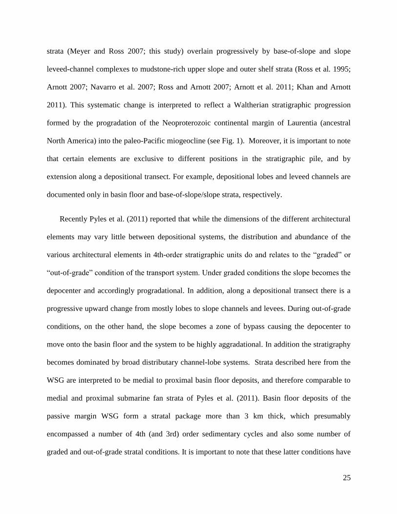
strata (Meyer and Ross 2007; this study) overlain progressively by base-of-slope and slope
leveed-channel complexes to mudstone-rich upper slope and outer shelf strata (Ross et al. 1995;
Arnott 2007; Navarro et al. 2007; Ross and Arnott 2007; Arnott et al. 2011; Khan and Arnott
2011). This systematic change is interpreted to reflect a Waltherian stratigraphic progression
formed by the progradation of the Neoproterozoic continental margin of Laurentia (ancestral
North America) into the paleo-Pacific miogeocline (see Fig. 1). Moreover, it is important to note
that certain elements are exclusive to different positions in the stratigraphic pile, and by
extension along a depositional transect. For example, depositional lobes and leveed channels are
documented only in basin floor and base-of-slope/slope strata, respectively.
Recently Pyles et al. (2011) reported that while the dimensions of the different architectural
elements may vary little between depositional systems, the distribution and abundance of the
various architectural elements in 4th-order stratigraphic units do and relates to the “graded” or
“out-of-grade” condition of the transport system. Under graded conditions the slope becomes the
depocenter and accordingly progradational. In addition, along a depositional transect there is a
progressive upward change from mostly lobes to slope channels and levees. During out-of-grade
conditions, on the other hand, the slope becomes a zone of bypass causing the depocenter to
move onto the basin floor and the system to be highly aggradational. In addition the stratigraphy
becomes dominated by broad distributary channel-lobe systems. Strata described here from the
WSG are interpreted to be medial to proximal basin floor deposits, and therefore comparable to
medial and proximal submarine fan strata of Pyles et al. (2011). Basin floor deposits of the
passive margin WSG form a stratal package more than 3 km thick, which presumably
encompassed a number of 4th (and 3rd) order sedimentary cycles and also some number of
graded and out-of-grade stratal conditions. It is important to note that these latter conditions have

26
been reported from slope deposits of the Isaac Formation where mass transport deposits, some up
to 135 m thick and dominated by slump, slide and debris flow deposits, episodically interrupt a
much more thickly developed stratigraphy dominated by leveed slope channels formed under
generally graded conditions (Arnott et al. 2011). Intuitively these changes should be manifest
also in the basin floor sedimentary record, and according to Pyles et al. (2011) in the abundance
of its composite architectural elements. To date no such intercalation has been observed in rocks
of the Kaza Group. Instead the sand-rich component of basin floor strata show a consistent km-
scale (vertical) change from almost exclusively terminal splays deposited in the medial part of
the lobe system to terminal splays with common distributary channel deposits in the more
proximal basin floor. The question, then, is whether the passive margin WSG, which is generally
graded and only temporary out of grade, and therefore different than the passive margin, out-of-
grade Pab Sandstone (Pyles et al. 2011), the rule or the exception? Future (seismic) research is
needed to describe the temporal and spatial evolution of large, passive margin depositional
systems in order to document and link changes between stratigraphic grade and sedimentation
patterns on the slope and basin floor.
CONCLUSION
Basin-floor deposits are generally one of the least-well understood parts of the submarine
turbidite depositional system, especially at the small, architectural element scale. This study of
the Middle and Upper Kaza groups of the Windermere turbidite system adds to the global
knowledge base by describing 6 distinct facies from basin-floor outcrops of the Middle and
Upper Kaza groups. These, then, populate 7 architectural elements, which in turn comprise lobes
27
that make up the basin-floor stratigraphy of the Middle and Upper Kaza. Major elements include
sand-filled scours, avulsion splays comprising matrix-rich sandstone, small and large channels
with mixed sandstone and mudstone fills, sheet-like sandstones, sheet-like fine-grained units and
debrites. This study shows that, except for debrites, all elements comprise similar facies, but that
it is the overall shape and dimensions of these elements, and more importantly, the internal
organization of the constituent lithofacies that uniquely populate each of the different
architectural elements.
Comparison of architectural element dimensions between the WSG and other systems
reveals a similarity in scale across various fans. This suggests that the detailed lithological data
presented in this study can then be extrapolated to other basin-floor studies, and therein provide a
robust predictive tool for sediment type and distribution across similarly large, graded, mixed
sand-and-mud basin-floor fans, even where lithological data are limited.
REFERENCES
Aalto, K.R., 1971, Glacial marine sedimentation and stratigraphy of the Toby conglomerate
(upper Proterozoic), southeastern British Columbia, northwestern Idaho and northeastern
Washington: Canadian Journal of Earth Sciences - Revue Canadienne des Sciences de la
Terre, v. 8, p. 753–787.
Adrian, R.J., 2010, Closing in on models of wall turbulence: Science, v. 329, p. 155-156.
28
Alexander. J., McLelland, S.J., Gray, T.E., Vincent, C.E., Leeder, M.R., and Ellett, S., 2008,
Laboratory sustained turbidity currents form elongate ridges at channel mouths:
Sedimentology, v. 55, p. 845-868.
Allen, J.R.L., 1991, The Bouma division A and the possible duration of turbidity currents:
Journal of Sedimentary Petrology, v. 61, no. 2, p. 291-295.
Amos, K.J., Peakall, J., Bradbury, P.W., Roberts, M., Keevil, G., and Gupta, S., 2010, The
influence of bend amplitude and planform morphology on flow and sedimentation in
submarine channels: Marine and Petroleum Geology, v. 27, p. 1431–1447.
Arnott, R.W.C., 2007, Stratigraphic architecture and depositional processes of a proximal
crevasse splay and genetically related, sinuous channel fill, Isaac Formation, British
Columbia, Canada: in T. H. Nilsen, R. D. Shew, G. S. Steffens, and J. R. J. Studlick, eds.,
Atlas of deep-water outcrops: AAPG Studies in Geology 56.
Arnott, R.W.C., 2012, Turbidites, and the case of the missing dunes: Journal of Sedimentary
Research, v. 82, p. 1-6.
Arnott, R.W.C., and Hand, B.M., 1989, Bedforms, primary structures and grain fabric in the
presence of suspended sediment rain: Journal of Sedimentary Petrology, v. 59, no. 6, p.
1062-1069.
Arnott, R.W.C., Wallace, K., and Laurin, J., 2011, Stratal architecture and temporal evolution of
a passive margin mass-transport deposit, Neoproterozoic Isaac Formation, Cariboo
Mountains, British Columbia, Canada, In: Mass-transport deposits in deepwater settings
29
(Eds. Shipp, R.C., Weimer, P., Posamentier, H.W.), SEPM Special Publication no. 96,
532 pp.
Baas, J.H., and Best, J.L., 2002, Turbulence modulation in clay-rich sediment-laden flows and
some implications for sediment deposition: Journal of Sedimentary Research, v. 72, p.
336-340.
Baas, J.H. and Best, J.L. 2008, The dynamics of turbulent, transitional and laminar clay-laden
flow over a fixed current ripple: Sedimentology, v. 55, p. 635–666.
Bagnold, R.A., 1954, Experiments on a gravity-free dispersion of large solid spheres in a
Newtonian fluid under shear: Proceedings of the Royal Society of London, v. 225, p.
49-63.
Bagnold, R.A., 1962, Auto-suspension of transported sediment: turbidity currents: Proceedings
of the Royal Society of London, v. 265, p. 315-319.
Beaubouef, R.T., Rossen, C., Zelt, F.B., Sullivan, M.D., Mohig, D.C., and Jennette, D.C., 1999,
Deep-water sandstones, Brushy Canyon formation, West Texas. In: Field Guide for
AAPG Hedberg Field Research Conference. AAPG Continuing Education Course Note
Series, vol. 40, p. 48.
Beaubouef, R.T., Van Wagoner, J.C., and Adair, N.L., 2003, Ultra-high resolution 3-D
characterization of deep-water deposits-II: Insignts into the evolution of a submarine fan
and comparisons with river deltas: AAPG Search and Discovery Article #90013.

30
Bell, R.T., Jefferson, C.W., and Brennan, E., 1987, An hypothesis for an Australian- Canadian
connection in the late Proterozoic and the birth of the Pacific Ocean: Australian Institute
of Mining and Metallurgy, Pacific Rim Congress '87, Parksville, Victoria, p. 39–50.
Bernhardt, A., Jobe, Z.R., and Lowe, D.R., 2011, Stratigraphic evolution of a submarine
channel-lobe complex system in a narrow fairway within the Magallanes foreland basin:
Cerro Toro Formation, southern Chile: Marine and Petroleum Geology, v. 28, p. 785-806.
Bouma, A.H., 1962, Sedimentology of some Flysch deposits: A graphic approach to facies
interpretation: Elsevier, 168 pp.
Campbell, R.B., Mountjoy, E.W., and Young, F.G,. 1973, Geology of McBride map-area, British
Columbia: Geological Survey of Canada, Paper 72–35, 104 p.
Carr, M., and Gardner, M.H., 2000, Portrait of a basin- floor fan for sandy deep-water systems,
Permian lower Brushy Canyon Formation, west Texas, in A. H. Bouma and C. G. Stone,
eds., Fine-grained turbidite systems: AAPG Memoir 72/SEPM Special Publication 68, p.
215–232.
Colpron, M., Logan, J.M., and Mortensen, J.K., 2002, U-Pb zircon age constraint for late
Neoproterozoic rifting and initiation of the lower Paleozoic passive margin of western
Laurentia: Canadian Journal of Earth Sciences = Revue Canadienne des Sciences de la
Terre, v. 39, p. 133–143.
Deptuck, M.E., Piper, D.J.W., Savoye, B., and Gervais, A., 2008, Dimensions and architecture of
late Pleistocene submarine lobes off the northern margin of East Corsica: Sedimentology,
v. 55, p. 869-898.
31
Drinkwater, N.J., and Pickering, K.T., 2001, Architectural elements in a high-continuity sand-
prone turbidite system, late Precambrian Kongsfjord Formation, northern Norway:
Application to hycrocarbon reservoir characterization: American Association of
Petroleum Geologists Bulletin, v. 85, no. 10, p. 1731-1757.
Elliott, T., 2000, Depositional architecture of a sand-rich, channelized turbidite system: the upper
Carboniferous Ross Sandstone Formation, western Ireland. In: Weimer, P., Slatt, R.M.,
Coleman, J., Rossen, N.C., Nelson, H., Bouma, A.H., Styzen, M.J., Lawrence, D.T.
(Eds.), Deep-water Reservoirs of the World. GCSSEPM, p. 342-373.
Emery, D., and Myers, K.J., 1996, Sequence stratigraphy: Oxford, Blackwell Science, 297 p.
Fildani,A., Shultz, M.R., Graham, S.A., and Leier, A., 2007, A deep-water amalgamated sheet
system, Punta Barrosa Formation, Marina’s Cliff, Chile. In: Nilsen, T., Shew, R.,
Steffens, G., Studlick, J. (Eds.), Deep-water Outcrops of the World Atlas: American
Association of Petroleum Geologists Studies in Geology, 56, pp. 125-127.
Fildani, A., Hubbard, S.M., and Romans, B.W., 2009. Stratigraphic Evolution of Deepwater
Architecture: Examples of Controls and Depositional Styles from the Magallanes Basin,
Chile. In: Society of Sedimentary Geology, Fieldtrip Guidebook 10, p. 73.
Flint, S.S., Hodgson, D.M., Sprague, A.R., Brunt, R.L., Van der Merwe, W.C., Figueiredo, J.,
Prelat, A., Box, D., Di Celma, C., and Kavanagh, J.P., 2011. Depositional architecture
and sequence stratigraphy of the Karoo basin floor to shelf edge succession, Laingsburg
depocentre, South Africa: Marine and Petroleum Geology, v. 28, p. 658-674.
32
Gardner, M.H., and Borer, J.M., 2000, Submarine channel architecture along a slope to basin
profile, Brushy Canyon Formation, west Texas. In: Bouma, A.H., Stone, C.G. (Eds.),
Fine-grained Turbidite Systems. American Association of Petroleum Geologists Memoir
72 195e214. SEPM Special Publication, vol. 68.
Gardner, J.V., Bohannon, R.G., Field, M.E., and Masson, D.G., 1996, The morphology,
processes, and evolution of Monterey Fan: a revisit. In: Gardner, J.V., Field, M.E.,
Twichell, D.C. (Eds.), Geology of the United States' Seafloor: The view from GLORIA.
Cambridge Univ. Press, New York, NY, p. 193–220.
Gardner, M.H., Borer, J.M., Melick, J.J., Mavilla, N., and Wagerle, R.N., 2003, Stratigraphic
process-response model for submarine channels and related features from studies of
Permian Brushy Canyon outcrops, west Texas: Marine and Petroleum Geology 20, 757-
787.
Gervais, A., Savoye, B., Mulder, T., and Gonthier, E., 2006, Sandy modern turbidite lobes: a
new insight from high resolution seismic data: Marine and Petroleum Geology, v. 23, p.
485–502.
Google Earth, 2005, Castle Creek and Mt. Quanstrom exposure locations. 10U 690462.73mE
and 5876480.73mN. ©Cnes/Spot 2012, ©Province of British Columbia 2010, ©Google
2012. http://www.earth.google.com [December 16 2012]
Groenenberg, R.M., Hodgson, D.M., Prélat, A., Luthi, S.M., and Flint, S.S., 2010, Flow-deposit
interaction in submarine lobes: insights from outcrop observations and process-based
numerical model realisations: Journal of Sedimentary Research, v. 80, p. 252–267.
33
Hall, J.W., and Ewing, D., 2007, Three-dimensional turbulent wall jets issuing from moderate-
aspect-ratio rectangular channels: AIAA Journal, v. 45, no. 6, p. 1177-1186.
Hiscott, R.N., 1994, Loss of capacity, not competence, as the fundamental process governing
turbidity currents: Journal of Sedimentary Research, v. 64, p. 209-214.
Hodgson, D.M., Flint, S.S., Hodgetts, D., Drinkwater, N.J., Johannessen, E.J., and Luthi, S.M.,
2006, Stratigraphic evolution of fine-grained submarine fan systems, Tanqua depocenter,
Karoo Basin South Africa. Journal of Sedimentary Research, v. 76, p. 19-39.
Hogg, A.J., Huppert, H.E., and Dade, W.B., 1997, Erosion by planar turbulent wall jets: Journal
of Fluid Mechanics, v. 338, p. 317-340.
Huang, H., Imran, J., Pirmez, C., Zhang, Q., and Chen, G., 2009, The critical densiometric
Froude number of subaqueous gravity currents can be non-unity or non-exitent: Journal
of Sedimentary Research, v. 79, p. 479-485.
Hubbard, S.M., Romans, B.W., Graham, S.A., 2008. Deep-water foreland basin deposits of the
Cerro Toro Formation, Magallanes Basin, Chile: architectural elements of a sinuous basin
axial channel belt: Sedimentology, v. 55, p. 1333-1359.
Jaeger, H.M., Nagel, S.R., and Behringer, R.O., 1996, The physics of granular materials: Physics
Today, v. 49, p. 32-36.
Jegou, I., Savoye, B., Pirmez, C., and Droz, L., 2008, Channel–mouth lobe complex of the recent
Amazon Fan: the missing piece: Marine Geology, v. 252, p. 62–77.

34
Johnson, S.D., Flint, S., Hinds, D., and De Ville Wickens, H., 2001, Anatomy, geometry and
sequence stratigraphy of basin floor to slope turbidite systems, Tanqua Karoo, South
Africa: Sedimentology, v. 48, p. 987-1023.
Karlstrom, K. E., Ahall, K.-I., Harlan, S. S., Williams, M. L., McLelland, J. and Geissman, J. W.,
2001, Long-lived (1.8–1.0 Ga) convergent orogen in southern Laurentia, its extensions to
Australia and Baltica, and implications for refining Rodinia: Precambrian Research, v.
111, p. 5–30.
Kendall, B. S., Creasar, R.A., Ross, G.M., and Selby, D.S., 2004, Constraints on the timing of
Marinoan “Snowball Earth” glaciation by 187Re–187Os dating of a Neoproterozoic,
post-glacial black shale in western Canada: Earth and Planetary Science Letters, v. 222,
p. 729–740.
Kenyon, N. H., and Millington, J., 1995, Contrasting deep-sea depositional systems in the Bering
Sea, in K. T. Pickering, R. N. Hiscott, N. H. Kenyon, F. Ricci Lucchi, and R. D. A.
Smith, eds., Atlas of deep water environments: architectural style in turbidite systems:
London, Chapman and Hall, p. 196–202.
Khan, Z., and Arnott, R.W.C., 2010, Experimental modelling of multiple non-climbing ripple set
beds from suspended particle fallout: American Association of Petroleum Geologists
2010 Annual Convention and Exhibition, Abstracts Volume 19, p. 131.
Kneller, B., and Branney, M.J., 1995, Sustained high-density turbidity currents and deposition of
thick massive sands: Sedimentology, v. 42, p. 607-616.
35
Leclair, S.F., and Arnott, R.W.C., 2003, Coarse-tail graded, structureless strata: indicators of an
internal hydraulic jump: in Roberts, H.H., Rosen, N.C., Filion, R.H., and Anderson, J.B.,
eds., Shelf Margin Deltas and Linked Down Slope Petroleum Systems: Global
Significance and Future Exploration Potential: SEPM, Gulf Coast Section, Houston, p.
817–836.
Leclair, S.F., and Arnott, R.W.C., 2005, Parallel lamination formed by high-density turbidity
currents: Journal of Sedimentary Research, v. 75, p. 1–5.
Leeder, M.R., 1982, Sedimentology; Process and Product: London, Unwin Hyman, 344 p.
Lowe, D.R., 1975, Water escape structures in coarse-grained sediments: Sedimentology, v. 22, p.
157-204.
Lowe, D.R., 1982, Sediment gravity flows: II. Depositional models with special reference to the
deposits of high-density turbidity currents: Journal of Sedimentary Petrology, v. 52, p.
279-297.
Lund, K., Aleinikoff, J.N., Evans, K.V., and Fanning, C.M., 2003, SHRIMP U-Pb
geochronology of Neoproterozoic Windermere Supergroup, central Idaho: Implications
for rifting of western Laurentia and synchroneity of Sturtian glacial deposits: Geological
Society of America Bulletin, v. 115, p. 349–372.
Maier, K.L., Fildani, A., Paull, C.K., Graham, S.A., McHargue, T.R., Caress, D.W., and
McGann, M., 2011, The elusive character of discontinuous deep-water channels: New
insights from Lucia Chica channel system, offshore California: Geology, v. 39, p. 327-
330.
36
Martinsen, O.J., Lien, T., and Walker, R.G., 2000, Upper Carboniferous deep water sediments,
western Ireland: analogues for passive margin turbidite plays. In: Weimer, P., Slatt, R.M.,
Coleman, J., Rossen, N.C., Nelson, H., Bouma, A.H., Styzen, M.J., Lawrence, D.T.
(Eds.), Deep-water Reservoirs of the World. Gulf Coast Section-SEPM, p. 533-555.
Martinsen, O.J., Lien, T., Walker, R.G., and Collinson, J.D., 2003, Facies and sequential
organization of a mudstone-dominated slope and basin floor succession: the Gull Island
Formation, Shannon basin, western Ireland: Marine and Petroleum Geology, v. 20, p.
789-807.
Marusic, I., Mathis, R., and Hutchins, N., 2010, Predictive model for wall-bounded turbulent
flow: Science, v. 329, p. 193-196.
Marvinney, K.L., Hoskinson, K.N., Smith, M., Terlaky, V., Arnott, R.W.C., and Chiarenzelli,
J.R., 2009, Geochemistry of Neoproterozoic Mudrocks from the Windermere
Supergroup: Geological Society of America Northeastern Section 44th Annual Meeting
March 22-24 2009. Poster Presentation
Meyer, L., and Ross, G.M., 2007, Channelized lobe and sheet sandstones of the Upper Kaza
Group basin-floor turbidite system (Windermere Supergroup), British Columbia, Canada:
in T. H. Nilsen, R. D. Shew, G. S. Steffens, and J. R. J. Studlick, eds., Atlas of deep-
water outcrops: AAPG Studies in Geology 56.
Miall, A.D., 1985, Architectural-element analysis: A new method of facies analysis applied to
fluvial deposits: Earth-Science Reviews, v. 22, p. 261–308.
37
Middleton, G.V., and Hampton, M.A., 1973, Sediment gravity flows: mechanics of flow and
deposition. In: Turbidity and Deep Water Sedimentation (Eds G.V. Middleton and A.H.
Bouma), SEPM, Pacific Section, Short Course Lecture Notes, 1-38.
Morris, S. A., Kenyon, N.H., Limonov, A.H., and Alexander, J., 1998, Downstream changes of
large-scale bedforms in turbidites around the Valencia channel mouth, north-west
Mediterranean: implications for palaeoflow reconstruction: Sedimentology, v. 45, p. 365–
377.
Mulder, T., and Alexander, J., 2001, The physical character of subaqueous density flows and
their deposits: Sedimentology, v. 48, no. 2, p. 269-299.
Mulder, T., and Etienne, S., 2010, Lobes in deep-sea turbidite systmems: State of the art:
Sedimentary Geology, v. 229, p. 75-80.
Navarro, L., Khan Z., and Arnott, R.W.C., 2007, Architecture of a deep-water channel levee
complex: Channel 3, Castle Creek South, Isaac Formation, Windermere Supergroup,
Bristish Columbia, Canada, in T. H. Nilsen, R. D. Shew, G. S. Steffens, and J. R. J.
Studlik, eds., Atlas of deep-water outcrops: AAPG Studies in Geology 56, p. 93–96.
Normark, W.R., 1978, Fan valleys, channels, and depositional lobes on modern, submarine fans:
characters for recognition of sandy turbidite environments, American Association of
Petroleum Geologists Bulletin, v. 62, p. 912-931.
Normark, W. R., Piper, D. J. W., and Hess, G. R., 1979, Distributary channels, sand lobes, and
mesotopography of Navy submarine fan, California borderland, with applications to
ancient fan sediments: Sedimentology, v. 26, p. 749–774.
38
Parsons, J.D., Schweller, W.J., Stelting, C.W., Southard, J.B., Lyons, W.J., and Grotzinger, J.P.,
2002, A preliminary experimental study of turbidite fan deposits: Journal of Sedimentary
Research, v. 72, no. 5, p. 619-628.
Piper, D.J.W., Hiscott, R.N., and Normark, W.R., 1999, Outcrop- scale acoustic facies analysis
and latest Quaternary development of Hueneme and Dume submarine fans, offshore
California: Sedimentology, v. 46, p. 47-78.
Piper, D.J.W., Normark, W.R., 2001, Sandy fans – from Amazon to Huemene and beyond:
American Association of Petroleum Geologists Bulletin, v. 85, no. 8, p. 1407-1438.
Pickering, K.T., and Clark, J.D., 1996, Architectural elements and growth patterns of submarine
channels: application to hydrocarbon exploration: American Association of Petroleum
Geologists Bulletin, v. 80, no. 2, p. 194–221.
Posamentier, H.W., and Kolla, V., 2003, Seismic geomorphology and stratigraphy of
depositional elements in deep-water settings: Journal of Sedimentary Research, v. 73, no.
3, p. 367-388.
Postma, G., Nemec, W., and Kleinspehn, K.L., 1988, Large floating clasts in turbidites: a
mechanism for their emplacement: Sedimentary Geology, v. 58, p. 47-61.
Prélat, A., Hodgson, D.M., and Flint, S.S., 2009, Evolution, architecture and hierarchy of
distributary deep-water deposits: a high-resolution outcrop investigation from the
Permian Karoo Basin, South Africa: Sedimentology, v. 56, p. 2132-2154.
39
Prélat, A., Covault, J.A., Hodgson, D.M., Fildani, A., and Flint, S.S., 2010, Intrinsic controls on
the range of volumes, morphologies, and dimensions of submarine lobes: Sedimentary
Geology, v. 232, p. 66-76.
Pyles, D.R., 2007, Architectural elements in a ponded submarine fan, Carboniferous Ross
Sandstone, western Ireland. In: Nilsen, T.H., Shew, R.D., Steffens, G.S., Studlick, J.R.J.
(Eds.), Atlas of Deepwater Outcrops. American Association of Petroleum Geologists
Studies in Geology, v. 56, p. 19.
Pyles, D.R., 2008, Multiscale stratigraphic analysis of a structurally confined submarine fan:
Carboniferous Ross Sandstone, Ireland: AAPG Bulletin, v. 92, p. 557–587.
Pyles, D.R., Syvitski, J.P.M., and Slatt, R.M., 2011, Defining the concept of stratigraphic grade
and applying it to stratal (reservoir) architecture and evolution of the slope-to-basin
profile: An outcrop perspective: Marine and Petroleum Geology, v. 28, p. 675-697.
Romans, B.W., Fildani, A., Hubbard, S.M., Covault, J.A., Fosdick, J.C., and Graham, S.A.,
2011, Evolution of deep-water stratigraphic architecture, Magallanes Basin, Chile:
Marine and Petroleum Geology, v 28, no. 3, p. 612-628.
Ross, G.M., McMechan, M.E., and Hein, F.J., 1989, Proterozoic history: birth of the
miogeocline, in B. D. Ricketts, ed., The western Canada sedimentary basin: Canadian
Society of Petroleum Geologists, p. 79–104.
Ross, G.M., 1991, Tectonic setting of the Windermere Supergroup revisited: Geology, v. 19, p.
1125-1128.
40
Ross, G.M., Bloch, J.D., and Krouse, H.R., 1995, Neoproterozoic strata of the southern Canadian
Cordillera and the isotopic evolution of seawater sulfate: Precambrian Research, v. 73, p.
71-99.
Ross, G.M., and Arnott, R.W.C., 2007, Regional Geology of the Windermere Supergroup,
Southern Canadian Cordillera and Stratigraphic Setting of the Castle Creek Study Area,
in T. H. Nilsen, R. D. Shew, G. S. Steffens, and J. R. J. Studlick, eds., Atlas of Deep-
Water Outcrops: AAPG Studies in Geology 56.
Saller, A., Werner, K., Sugiaman, F., Cebastiant, A., May, R., Glenn, D., and Barker, C., 2008,
Characteristics of Pleistocene deep-water fan lobes and their application to an upper
Miocene reservoir model, offshore East Kalimantan, Indonesia: AAPG Bulletin, v. 92,
no. 7, p. 919-949.
Schwarz, E., and Arnott, R.W.C., 2007, Anatomy and evolution of a slope channelcomplex set
(Neoproterozoic Isaac Formation, Windermere Supergroup, southern Canadian
Cordillera): implications for reservoir characterization: Journal of Sedimentary Research,
v. 77, p. 89–109.
Sinclair, H.D., and Tomasso, M., 2002, Depositional evolution of confined turbidite basins:
Journal of Sedimentary Research, v. 72, p. 451-456.
Sixsmith, P.J., Flint, S.S., Wickens, H.deV., and Johnson, S.D., 2004, Anatomy and stratigraphic
development of a Basin floor turbidite system in the Laingsburg Formation, Main Karoo
Basin, South Africa. Journal of Sedimentary Research, v. 74, p. 239-254.
41
Smith, M.D., 2009, Stratigraphic and geochemical evolution of the Old Fort Point Fm., southern
Canadian Cordillera: the deep-marine perspective of Ediacaran post-glacial
environmental change. Ph. D. Thesis, University of Ottawa.
Smith, M.D., Arnaud, E., Arnott, R.W.C., and Ross, G.M., 2012, The record of Neoproterozoic
glaciations in the Windermere Supergroup, southern Canadian Cordillera, In: The
Geological Record of Neoproterozoic Glaciations (eds. Arnaud, E., Halverson, G.P.,
Shields-Zhou, G.), Geological Society Memoir no. 36., 752 pp.
Sprague, A.R., Sullivan, M.D., Campion, K.M., Jensen, G.N., Goulding, F.J., Garfield, T.R.,
Sickafoose, D.K., Rossen, C., Jennette, D.C., Beaubouef, R.T., Abreu, V., Ardill, J.,
Porter, M.L., and Zelt, F.B., 2002, The physical stratigraphy of deep-water strata: A
hierarchical approach to the analysis of genetically related stratigraphic elements for
improved reservoir prediction (abs.): AAPG Annual Meeting Program, p. A167.
Stow, D.A.V., and Johansson, M., 2000, Deep-water massive sands: nature, origin and
hydrocarbon implications: Marine and Petroleum Geology, v. 17, p. 145-174.
Straub, K.M., Mohrig, D.C., Buttles, J., McElroy, B., and Pirmez, C., 2008, Interactions between
turbidity currents and topography in aggrading sinuous submarine channels: A laboratory
study: Geological Society of America Bulletin, v. 120, p. 368–385.
Sullivan, M., Jensen, G., Goulding, F., Jennette, D., Foreman, L., and Stern, D., 2000,
Architectural analysis of deep-water outcrops: implications for exploration and
development of the Diana sub-basin, western Gulf of Mexico. In: Weimer, P., Slatt,
R.M., Coleman, J., Rossen, N.C., Nelson, H., Bouma, A.H., Styzen, M.J., Lawrence, D.T.
(Eds.), Deep-water Reservoirs of the World. GCS-SEPM, p. 1010-1031.
42
Sumner, E., Amy, L., and Talling, P.J., 2008, Deposit structure and processes of sand deposition
from a decelerating sediment suspension: Journal of Sedimentary Research, v. 78, p. 529
- 547.
Talling, P.J., Amy, L.A., Wynn, R.B., Peakall, J., and Robinson, M., (2004) Beds comprising
debrite sandwiched within cogenetic turbidite: origin and widespread occurrence in distal
depositional environments, Sedimentology, v. 51, p163-194.
Talling, P.J., Masson, D.G., Sumner, E.J., and Malgesini, G., 2012, Subaqueous sediment density
flows: Depositional processes and deposit types: Sedimentology, v. 59, p. 1937-2003.
Twitchell, D.C., Schwab, W.C., Nelson, C.H., Kenyon, N.H., and Lee, H.J., 1992,
Characteristics of a sandy depositional lobe on the outer Mississippi fan from SeaMARC
IA sidescan sonar images: Geology, v. 20, p. 689-692.
Vail, P.R., Mitchum, R.M., and Thompson, S., 1977, Seismic stratigraphy and global changes of
sea level, part 3: Relative changes of sea level from coastal onlap, in C.E. Clayton, ed.,
Seismic stratigraphy - applications to hydrocarbon exploration: Tulsa, Oklahoma,
American Association of Petroleum Geologists Memoir 26, p. 63-81.
Wynn, R.B., Kenyon, N.H., Masson, D.G., Stow, D.A.V., and Weaver, P.P.E., 2002,
Characterization and recognition of deep-water channel-lobe transition zones: AAPG
Bulletin, V. 86, no. 8, p. 1441-1462
Yu, B., Cantelli, A., Marr, J., Pirmez, C., O’Byrne, C., and Parker, G., 2006, Experiments on
self-channelized subaqueous fans emplaced by turbidity currents and dilute mudflows:
Journal of Sedimentary Research, v. 76, p. 889-902.

1
TABLES
Table 1: Description and interpretation of the six facies identified in basin-floor strata of the Windermere Supergroup. See Figures 3-8
for representative photographs.
Faci
es
Description Interpretation
Lithology Stratigraphic attributes
Sediment support and transport mechanism
Depositional process Type of flow
1
Massive to normally coarse-tail graded, upper very coarse to lower very coarse sub-arkose sandstone with locally dispersed sub-angular granules and pebbles up to 8 mm in diameter Matrix content is ~20-30% and consists of silt with minor chlorite and muscovite. Rounded to sub-angular mudclasts are present locally. Scintillometer measurements are between 40-60 counts per second (cps).
Beds range from several decimeters to >3 m thick. Basal contacts commonly undulate with scours up to 30-40 cm deep. Beds are commonly amalgamated. Pipe, dish, ball-and-pillow and flame structures are abundant locally.
Near the bed and front of the sediment-charged turbidity current grain-to-grain interaction and hindered settling are probably the primary support mechanisms, but near the top and towards the tail where the flow is less dense and grain size smaller, turbulence most probably dominates (Bagnold 1954, 1962; Middleton and Hampton 1973; Jaeger et al. 1996).
Structureless massive or graded beds indicate deposition from the base of the flow by gradual although rapid aggradation (Arnott and Hand 1989; Stow and Johansson 2000, Sumner et al. 2008). Here sediment concentration exceeded flow capacity (Allen 1991) and sediment was deposited rapidly from collapsing laminar sheared layers, preventing the initiation of traction current bed forms (Arnott and Hand 1989, Kneller and Branney 1995; Sumner et al. 2008). Sediment was replenished by downward settling from areas higher in the flow (Kneller and Branney 1995; Stow and Johansson 2000; Sumner et al. 2008). Mudclasts may have been transported in such flows along a density interface separating the lower, dense part of the current from the upper, more dilute part (Postma et al. 1988).
Poorly stratified concentrated density flows sensu Mulder and Alexander 2001 or high density turbidity current sensu Lowe 1982. The presence of dewatering and loading structures in coarse sandstone indicates rapid deposition of sand and short recurrence interval between depositional events (Lowe 1975; Stow and Johansson 2000).
2
Coarse-tail graded sandstone. Matrix is generally absent in the upper part of the bed and pores are filled with ferroan calcite cement. Scintillometer measurements range from 30-50 cps in the lower, graded sandstone part of the bed, and decrease to 20-30 cps in the well-sorted layer at the top.
Beds are typically ~1-2 m thick; bases are commonly erosional with shallow (<20 cm deep) scours. Beds are capped commonly with medium- to large-scale (5 cm to >1 meter) cross-stratified or planar-laminated sandstone.
Similar to Facies 1.
Basal graded part of bed is similar to deposition of Facies 1. Medium- and large-scale cross-stratification at the tops of beds are interpreted to be dunes whereas planar stratified sandstone is interpreted to represent plane bed transport in high or low concentration flows. Both formed of sediment reworked from the underlying structureless part of the bed.
Type of flow depositing the basal part of the bed is similar to Facies 1. The presence of dunes indicates that the formative flows were sufficiently dilute to permit the initiation, amplification and development of dune bed forms (Arnott 2012; Talling et al. 2012), whereas, if flows were faster and/or the sediment concentration too high, traction-transported sediment formed plane bed (Arnott 2012).
3 The basal part of the bed comprises coarse-tail graded sandstone similar to Facies 1. This,
Beds are ~1 m thick. Grain-size change is abrupt between the
The sediment support mechanism for the lower part of the bed is similar to Facies 1. The upper fine-
Depositional process of the graded basal part of beds is similar to Facies 1. In the upper part of the bed, high matrix content in the
The type of flow depositing the basal part of the bed is similar to Facies 1. The upper part of the bed was

2
then, is overlain abruptly by distinctly darker grey-coloured, fine and very fine sandstone. Small, rounded mudclasts are typically concentrated near abrupt grain size change within the bed. Scintillometer measurements range from 40-60 cps in the lower, graded sandstone part of the bed, and increase to 60-75 cps in the well-sorted layer at the top.
lower and upper part of the bed. The upper part comprises common planar and ripple cross-lamination, capped locally by a thin layer of siltstone.
grained part of the bed most probably indicate fully turbulent conditions in a low concentration flow (Mulder and Alexander 2001; Talling et al. 2012).
planar-laminated sandstone indicates capacity driven deposition that prevented formation of angular bed forms (Leclair and Arnott 2005; Sumner et al. 2008; Arnott 2012; Talling et al. 2012). The overlying unit of single-set, non-climbing ripple cross-stratification is analogous to the Bouma Tc division (Bouma 1962) formed under low rates of sediment fallout (Khan and Arnott 2010). The uppermost siltstone drape indicates deposition from the low energy tail part of flows and is analogous to the Bouma Td division (Bouma 1962).
deposited from a decelerating and longitudinally stratified flow with a high-concentration body depositing the relatively matrix-rich planar laminated unit, followed by a dilute tail that formed the ripple cross-stratified and then silt layers.
4
Massive to coarse-tail graded subarkose sandstone with a grain size ranging from lower medium to lower coarse sand, and commonly with abundant (30-50%) chlorite and muscovite matrix with minor silt, giving the rocks a distinctive dark grey-green colour. Rounded and elongated sandstone and mudstone clasts are locally common, and are typically sheared and highly plastically deformed; their abundance varies laterally over 10’s to 100’s of meters, but are vertically uniformly distributed within the bed. Scintillometer readings range from 50-70 cps.
Basal contacts are typically non-erosive. Bed thickness ranges from 10 cm to 1 m. Small-scale (<5cm thick) cross-stratification (i.e. ripple) is rare, but where present occurs at the top of the bed and contains notably less matrix.
The grain size and high matrix content indicate that turbulence, grain-to-grain interaction, buoyancy and hindered settling played important roles in suspending sediment (Mulder and Alexander 2001).
Distinctively poorly-sorted, matrix-rich, massive to subtly graded beds with abundant mudclasts represent capacity-driven deposition from flows undergoing extreme rates of sediment fallout (Hiscott 1994; Leclair and Arnott 2005). Such high rates of fallout completely suppressed the development of tractional bed forms (Arnott and Hand 1989; Leclair and Arnott 2005; Sumner et al. 2008). The ripple cross-stratified layer at the top of some beds is notably better sorted and finer grained, indicating deposition of new sediment sourced from the low energy, dilute tail part of flows (analogous to the Bouma Tc division; Bouma (1962)).
The poorly-sorted, matrix-rich nature of beds and the even distribution of dispersed mudclasts indicates that these flows were likely poorly stratified, and may have been transitional in nature between cohesive and non-cohesive flow (Talling et al. 2004, 2012; Baas and Best 2002, 2008). However most beds are coarse-tail graded suggesting that grain mobility was not entirely restricted and that some differential grain settling occurred.
5
Graded fine-grained sandstone to siltstone and mudstone. Scintillometer readings range from 60-65 cps in sandier intervals to over 120 cps in mud rich intervals.
Beds range from 1 cm to 20 cm thick. Beds typically composed of a thin structureless unit overlain by planar and/or cross-laminated sandstone, and topped by a thin silty cap.
Sediment was fully supported by fluid turbulence.
These beds are analogous to Bouma Tabcd(e) turbidites (Bouma 1962).
Relatively dilute, well stratified and fully turbulent flows.
6
Matrix-supported, ungraded conglomerate composed of a mud-rich matrix and chaotically dispersed sand- and mudstone clasts. Dispersed quartz pebbles are present also and locally abundant. Scintillometer readings tend to be highly variable, but generally are of the order of 50-70 cps.
Beds are ~1 to several 10’s of m thick. Clasts are typically sheared and deformed, but commonly preserve original stratification.
Matrix strength provides the main sediment support.
Deformed clasts indicate that they were consolidated but not lithified at the time of transport. The occurrence of large meter-scale clasts indicates that turbulence, which most likely would disintegrate unlithified clasts, was damped (Postma et al. 1988). The flow deposited by “en-masse” freezing (Mulder and Alexander 2001; Talling et al. 2012).
Cohesive debris flow with high (up to >90%) sediment concentration (Leeder 1982).

3
Table 2: Comparison of the dimensions of architectural elements reported from this study and other ancient and modern examples.
Fan Reference Age Tectonic Setting Main grain size
Lobe Isolated scours Feeder channel Distributary channel
Terminal splay Avulsion Splay
Fine-grained sheets
WSG This study Neoproterozoic Passive margin Mixed sand and mud, minor gravel
Several to several 10s km wide, few m up to 50 m thick
100-400 m wide, 1-5 m deep
>600 m (>1 km?) wide, 15 m deep
Several 100s m wide, up to 5 m deep
>1 km to several km wide, up to 10 m thick
Several 100s m wide, few dm to few m thick
~100 m to >2 km (potentially several 10’s of km) wide, <1 to ~35 m thick
Lower Brushy Canyon Formation
Carr and Gardner 2000
Permian Intra cratonic passive margin
Mixed sand and mud
30-150 m wide, 1-3 m deep
200 m wide, 6 m thick
> several km wide, 2-3 m thick
Golo fan system Deptuck et al. 2008; Gervais et al. 2010
Pleistocene Mixed sand and mud, minor gravel
2-14 km long, 1 to >10 km wide, 8-42 m thick
Up to 7 m deep, ~300 m wide
100 m wide, up to 10 m deep
Up to ~10 m thick, several km wide
Amazon fan Jegou et al. 2008
Modern Passive Margin Mixed sand and mud
21-83 km long, 6-25 km wide
3-5 m deep
Tanqua area of the Karoo Basin
Johnson et al. 2001
Permian Foreland basin Mixed sand and mud
300 m - 1 km wide, up to 18 m deep
Overall tabular sheet geometry that is mappable over several kms. Internally lithologically heterogeneous with internal scours and minor channelization
Termed amalgamated to layered sheets, up to ~ 10 m thick
Up to >15 km wide, 1 cm to >10 m thick
Umnak channel mouth
Kenyon and Millington 1995
Modern Mixed sand and mud
2.5 km long, 2 km wide, 5 m deep
Valencia Fan Morris et al. 1998
Modern Structure controlled passive margin
Mixed sand and mud
300 m long, 80 m wide, 8 m deep
Navy Fan Normark et al. 1979
Modern Active margin Sand rich 350 m long, 500 m wide 20 m deep
Up to 0.5 km wide, 5-15 m deep
Huemene and Dume fans
Piper et al. 1999
Quaternary Transpressive Mixed sand and mud
Termed shallow channel-fill subelement, 100-700 m wide, ~1 m thick, <15 km long
Termed gently lensing subelement 1-2 km wide, <2 m thick

4
Skoorsteenbergen Fm., Fan 3
Prélat et al. 2009
Permian Foreland basin Mixed sand and mud
Several 10s km across, 3-14 m thick
Termed lobe elements, 1-3 m thick
Several 10’s of km wide, 0.2-2 m thick
Ross Formation Pyles 2007 Carboniferous Transtensional Mixed sand and mud
Termed channels (may include feeder channels), 170 m wide, 4 m thick
Termed lobes 1900 m wide, 2 m thick
>18 km wide, 1-2 m thick
Offshore East Kalimantan
Saller et al. 2008
Pleistocene Complex extensional and compressional basin
Mixed sand and mud
7.5 km long, 3.5 km wide, 9-40 m thick
392 m wide, 13 m thick
161 m wide, 12.6 m thick, 2.2 km long
500-3000 m long, 400-1200 m wide, 4-13 m thick
Mississippi Fan Twitchell et al. 1992
Modern Passive margin Mixed sand and mud
150 km long, 50 km wide, 10-40 m thick
120 km long, 150-300 m wide, 8-10 m high levees that diminish in height downflow
20 km long, <100 m wide, <2 m relief; distal channels <75 m wide, no resolvable relief (identified by low backscatter)
Agadir Fan Wynn et al. 2002
Modern Passive margin Mixed sand and mud
500 m long, 250-500 m wide, 10.5 m deep; large amalgamated scours are up to 9 km wide
Lisbon Canyon Wynn et al. 2002
Modern Passive margin Mixed sand and mud
Axial part consisting of amalgamated scours 6 km long, 3 km wide; off-axis scours 1 km long and 800 m wide
Rhone Fan Wynn et al. 2002
Modern Passive margin Mixed sand and mud
1 km long, 500 m wide 20 m deep
Along down-stream transect widens from 500 m to 800 m, shallows from 80 m to less than 10 m deep

1
FIGURE CAPTIONS
Figure 1: Regional stratigraphy of the Windermere Supergroup in the Southern Canadian
Cordillera. This study focuses on the Middle and Upper Kaza groups, highlighted by red
rectangles (modified from Ross and Arnott 2007). Geochronological dates from Ross et
al. (1995), Lund et al. (2003), Kendall et al. (2004) and Colpron et al., (2002).

2
Figure 2: This study is based on fieldwork conducted on two periglacial exposures of the WSG
near McBride, British Columbia, Canada. Both outcrops comprise superbly exposed
vertically dipping beds. The Upper Kaza Group is exposed at Castle Creek and the
Middle Kaza is exposed at Mt. Quanstrom (background image ©Cnes/Spot 2012,
©Province of British Columbia 2010, ©Google 2012; inset image modified from Ross
1991).

3
\
Figure 3: A) Dispersed granules and pebbles are commonly distributed throughout the thickness
of beds of Facies 1. In this photograph a bed consisting of coarse-tail graded sandstone
and pebbly conglomerate erodes the underlying planar laminated sandstone (dashed line).
Pipe (B) and dish (C) structures are locally abundant in beds of Facies 1. D) In beds of
Facies 1 several dm long elongated mudclasts are abundant locally.

4
Figure 4: A) Well-sorted, 40 cm thick, over-steepened dune cross-stratified sandstone on top of a
poorly-sorted coarse-grained sandstone bed. B) Rare example of stacked dune sets
(arrows mark the set bases). C) Well-sorted, coarse-grained, red-brown coloured, planar-

5
laminated sandstone. D) Syndepositionally deformed cross-stratified or planar-laminated
sandstone is commonly observed. This picture shows foundered dune cross-stratified
sandstone (note deformed, but preserved lamination).
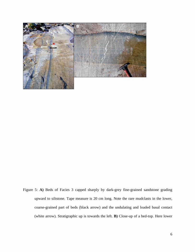
6
Figure 5: A) Beds of Facies 3 capped sharply by dark-grey fine-grained sandstone grading
upward to siltstone. Tape measure is 20 cm long. Note the rare mudclasts in the lower,
coarse-grained part of beds (black arrow) and the undulating and loaded basal contact
(white arrow). Stratigraphic up is towards the left. B) Close-up of a bed-top. Here lower
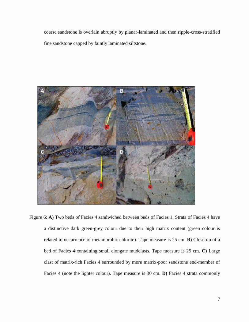
7
coarse sandstone is overlain abruptly by planar-laminated and then ripple-cross-stratified
fine sandstone capped by faintly laminated siltstone.
Figure 6: A) Two beds of Facies 4 sandwiched between beds of Facies 1. Strata of Facies 4 have
a distinctive dark green-grey colour due to their high matrix content (green colour is
related to occurrence of metamorphic chlorite). Tape measure is 25 cm. B) Close-up of a
bed of Facies 4 containing small elongate mudclasts. Tape measure is 25 cm. C) Large
clast of matrix-rich Facies 4 surrounded by more matrix-poor sandstone end-member of
Facies 4 (note the lighter colour). Tape measure is 30 cm. D) Facies 4 strata commonly
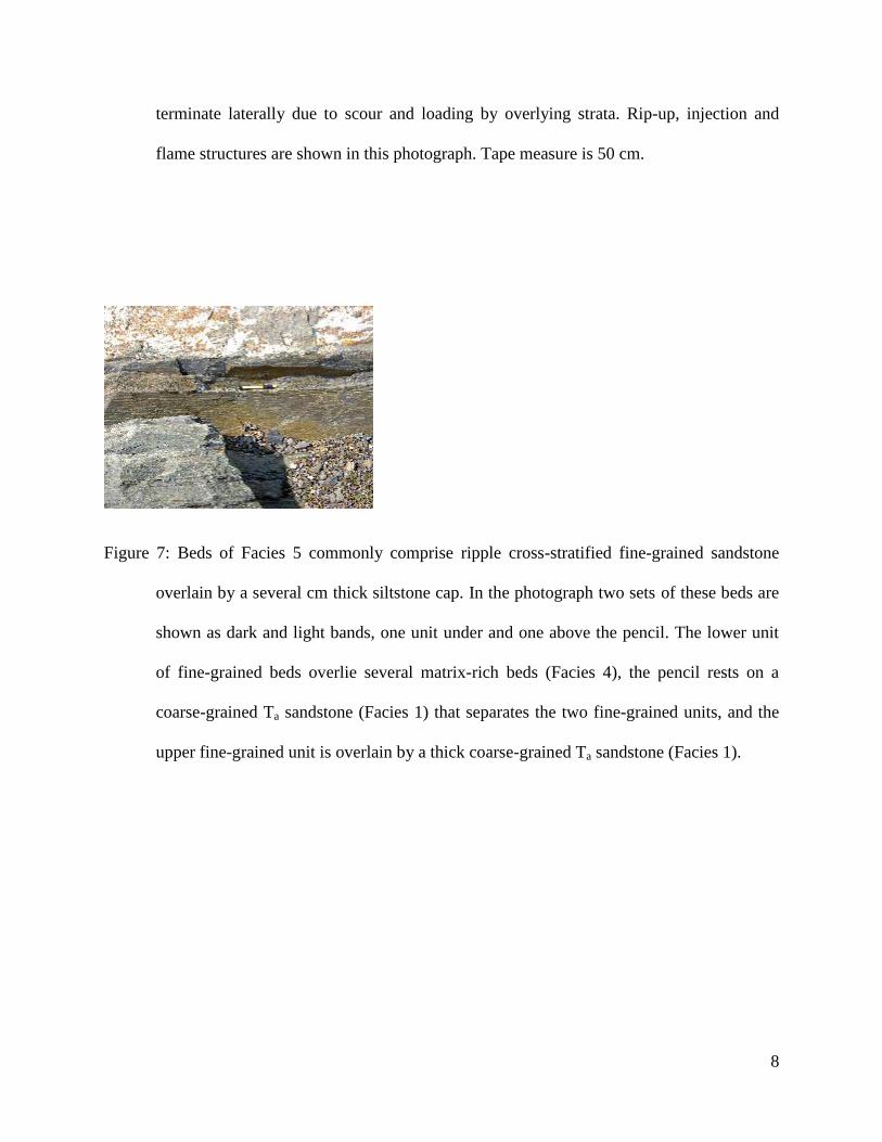
8
terminate laterally due to scour and loading by overlying strata. Rip-up, injection and
flame structures are shown in this photograph. Tape measure is 50 cm.
Figure 7: Beds of Facies 5 commonly comprise ripple cross-stratified fine-grained sandstone
overlain by a several cm thick siltstone cap. In the photograph two sets of these beds are
shown as dark and light bands, one unit under and one above the pencil. The lower unit
of fine-grained beds overlie several matrix-rich beds (Facies 4), the pencil rests on a
coarse-grained Ta sandstone (Facies 1) that separates the two fine-grained units, and the
upper fine-grained unit is overlain by a thick coarse-grained Ta sandstone (Facies 1).
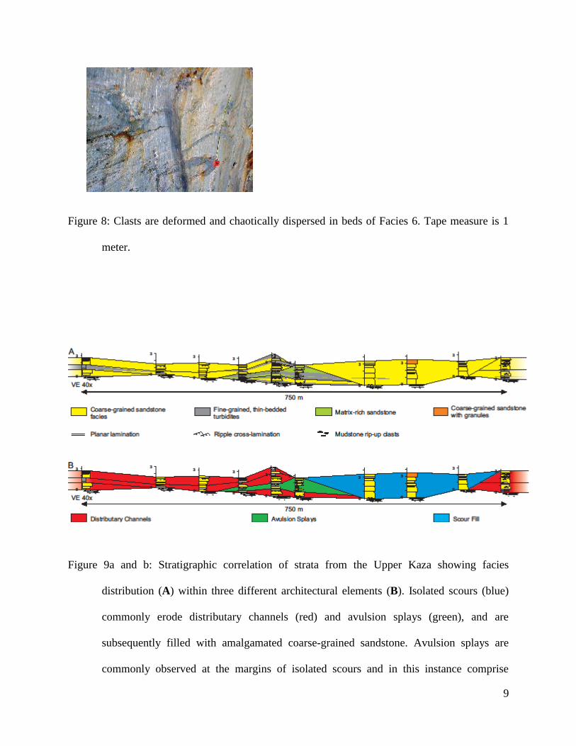
9
Figure 8: Clasts are deformed and chaotically dispersed in beds of Facies 6. Tape measure is 1
meter.
Figure 9a and b: Stratigraphic correlation of strata from the Upper Kaza showing facies
distribution (A) within three different architectural elements (B). Isolated scours (blue)
commonly erode distributary channels (red) and avulsion splays (green), and are
subsequently filled with amalgamated coarse-grained sandstone. Avulsion splays are
commonly observed at the margins of isolated scours and in this instance comprise
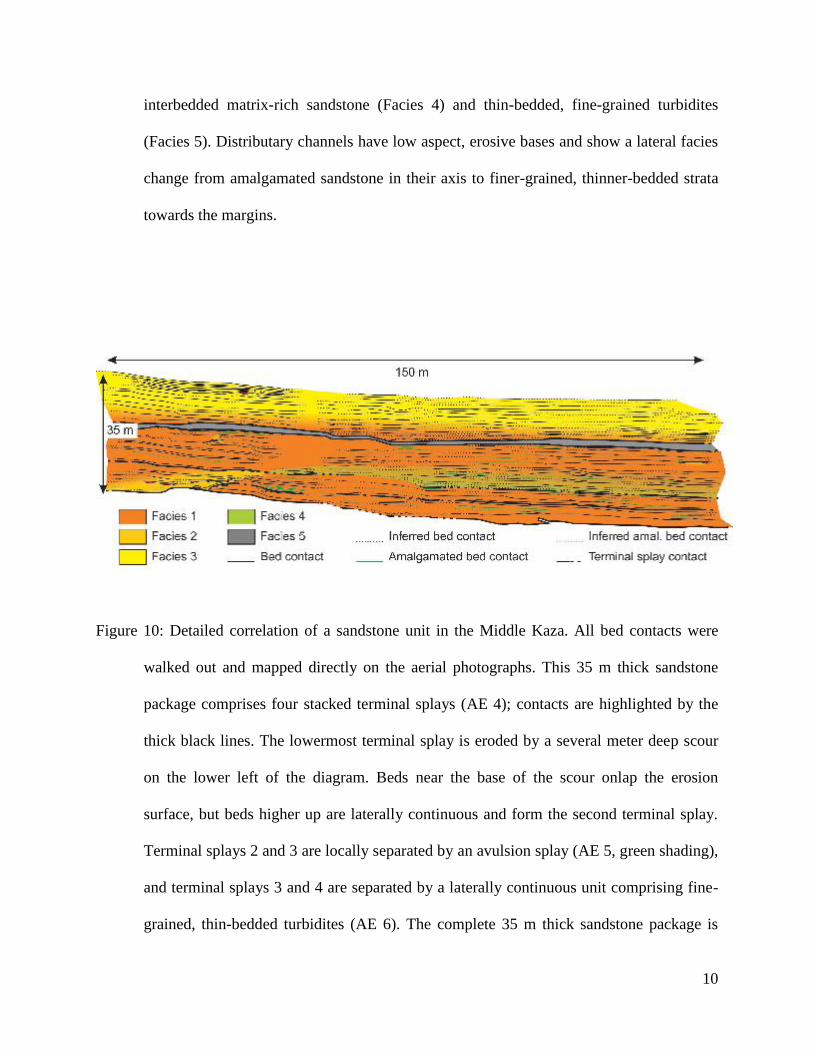
10
interbedded matrix-rich sandstone (Facies 4) and thin-bedded, fine-grained turbidites
(Facies 5). Distributary channels have low aspect, erosive bases and show a lateral facies
change from amalgamated sandstone in their axis to finer-grained, thinner-bedded strata
towards the margins.
Figure 10: Detailed correlation of a sandstone unit in the Middle Kaza. All bed contacts were
walked out and mapped directly on the aerial photographs. This 35 m thick sandstone
package comprises four stacked terminal splays (AE 4); contacts are highlighted by the
thick black lines. The lowermost terminal splay is eroded by a several meter deep scour
on the lower left of the diagram. Beds near the base of the scour onlap the erosion
surface, but beds higher up are laterally continuous and form the second terminal splay.
Terminal splays 2 and 3 are locally separated by an avulsion splay (AE 5, green shading),
and terminal splays 3 and 4 are separated by a laterally continuous unit comprising fine-
grained, thin-bedded turbidites (AE 6). The complete 35 m thick sandstone package is

11
interpreted to be the distal part of two depositional lobes, the lower consisting of three
amalgamated terminal splays (1-3), and the upper consisting of a single terminal splay
(4).
Figure 11: Evolution of a deep scour (feeder) channel in the Upper Kaza. Note that beds and
units are correlated laterally by physically walking them out in the field. A) The original
incision (erosional surface 1, or ES1) is approximately 15 m deep, overlain by fill unit 1,
an ~3 m thick fining-upward sandstone to siltstone unit. B) ES2 widens the channel by
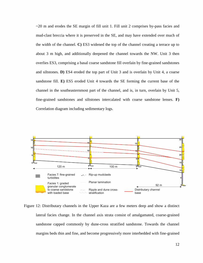
12
~20 m and erodes the SE margin of fill unit 1. Fill unit 2 comprises by-pass facies and
mud-clast breccia where it is preserved in the SE, and may have extended over much of
the width of the channel. C) ES3 widened the top of the channel creating a terrace up to
about 3 m high, and additionally deepened the channel towards the NW. Unit 3 then
overlies ES3, comprising a basal coarse sandstone fill overlain by fine-grained sandstones
and siltstones. D) ES4 eroded the top part of Unit 3 and is overlain by Unit 4, a coarse
sandstone fill. E) ES5 eroded Unit 4 towards the SE forming the current base of the
channel in the southeasternmost part of the channel, and is, in turn, overlain by Unit 5,
fine-grained sandstones and siltstones intercalated with coarse sandstone lenses. F)
Correlation diagram including sedimentary logs.
Figure 12: Distributary channels in the Upper Kaza are a few meters deep and show a distinct
lateral facies change. In the channel axis strata consist of amalgamated, coarse-grained
sandstone capped commonly by dune-cross stratified sandstone. Towards the channel
margins beds thin and fine, and become progressively more interbedded with fine-grained
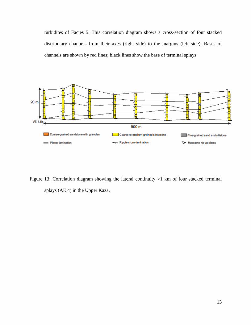
13
turbidites of Facies 5. This correlation diagram shows a cross-section of four stacked
distributary channels from their axes (right side) to the margins (left side). Bases of
channels are shown by red lines; black lines show the base of terminal splays.
Figure 13: Correlation diagram showing the lateral continuity >1 km of four stacked terminal
splays (AE 4) in the Upper Kaza.
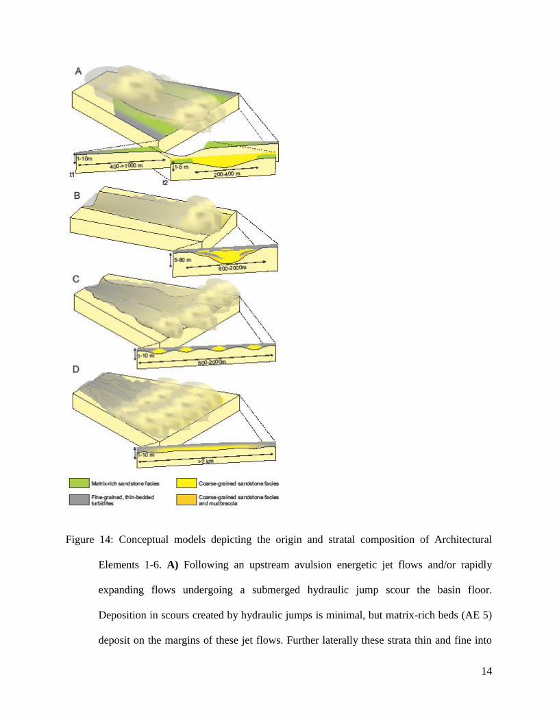
14
Figure 14: Conceptual models depicting the origin and stratal composition of Architectural
Elements 1-6. A) Following an upstream avulsion energetic jet flows and/or rapidly
expanding flows undergoing a submerged hydraulic jump scour the basin floor.
Deposition in scours created by hydraulic jumps is minimal, but matrix-rich beds (AE 5)
deposit on the margins of these jet flows. Further laterally these strata thin and fine into
15
AE 6. After abandonment (t2) scours are filled with coarse-grained sandstones that near
the top of the scour are laterally extensive and form a terminal splay (AE 4). B)
Alternatively, subsequent flows may exploit scours to form erosional feeder channels
(AE 2) that have a complex history of abandonment and reactivation, resulting in a
terraced base and lithologically complex fill. Channel axes comprise coarse-grained
sandstone fills intercalated with discontinuous thin-bedded, fine-grained units that
thicken towards the channel margins. The lower channel margin is overlain by an
intercalated assemblage of mud-clast breccia and coarse-grained sandstone. Following
abandonment the channel is filled with fine-grained turbidites intercalated with coarse-
grained sandstone lenses. C) Further downflow turbidity currents become unconfined and
develop distinct fast and slow moving supercells. Once formed these features become
diverted through broad, shallow conduits termed distributary channels (AE 3) that
eventually become filled with amalgamated coarse-grained sandstone in their axes. These
strata grade laterally and vertically to thinner, finer grained turbidites. Fine-grained strata
between widely spaced distributary channels are part of AE 6. D) Down-flow distributary
channels gradually become wider and shallower, eventually forming a laterally extensive
sheet-like deposit of coarse-grained sandstone (terminal splays; AE 4). After flows
become depleted of their coarse-grained load AE 4 rapidly transitions laterally into fine-
grained strata of AE 6.