rules for classification yachtsrules.dnvgl.com/docs/pdf/dnvgl/ru-yacht/2015-12/... · and retaining...
TRANSCRIPT
The content of this service document is the subject of intellectual property rights reserved by DNV GL AS ("DNV GL"). The useraccepts that it is prohibited by anyone else but DNV GL and/or its licensees to offer and/or perform classification, certificationand/or verification services, including the issuance of certificates and/or declarations of conformity, wholly or partly, on thebasis of and/or pursuant to this document whether free of charge or chargeable, without DNV GL's prior written consent.DNV GL is not responsible for the consequences arising from any use of this document by others.
The electronic pdf version of this document, available free of chargefrom http://www.dnvgl.com, is the officially binding version.
DNV GL AS
RULES FOR CLASSIFICATION
YachtsEdition December 2015
Part 3 Hull
Chapter 5 Composite scantlings

FOREWORD
DNV GL rules for classification contain procedural and technical requirements related to obtainingand retaining a class certificate. The rules represent all requirements adopted by the Society asbasis for classification.
© DNV GL AS December 2015
Any comments may be sent by e-mail to [email protected]
If any person suffers loss or damage which is proved to have been caused by any negligent act or omission of DNV GL, then DNV GL shallpay compensation to such person for his proved direct loss or damage. However, the compensation shall not exceed an amount equal to tentimes the fee charged for the service in question, provided that the maximum compensation shall never exceed USD 2 million.
In this provision "DNV GL" shall mean DNV GL AS, its direct and indirect owners as well as all its affiliates, subsidiaries, directors, officers,employees, agents and any other acting on behalf of DNV GL.

Part
3 C
hapt
er 5
Cha
nges
- c
urre
nt
Rules for classification: Yachts — DNVGL-RU-YACHT-Pt3Ch5. Edition December 2015 Page 3Composite scantlings
DNV GL AS
CURRENT – CHANGES
This is a new document.
The rules enter into force 1 July 2016.
Part
3 C
hapt
er 5
Con
tent
s
Rules for classification: Yachts — DNVGL-RU-YACHT-Pt3Ch5. Edition December 2015 Page 4Composite scantlings
DNV GL AS
CONTENTS
Current – changes...................................................................................................... 3
Section 1 Introduction............................................................................................... 61 General................................................................................................... 62 Documentation........................................................................................7
Section 2 Materials.....................................................................................................91 General................................................................................................... 92 Constituent materials............................................................................. 93 Mechanical testing................................................................................ 104 Testing procedures............................................................................... 13
Section 3 Structural arrangements...........................................................................151 General................................................................................................. 15
Section 4 Principles of structural design and calculation..........................................171 General................................................................................................. 172 Failure criteria...................................................................................... 183 Scantling calculation methods.............................................................. 19
Section 5 Hull girder (global) strength.................................................................... 211 General................................................................................................. 212 Hull girder global loads........................................................................ 213 Structural assessment.......................................................................... 22
Section 6 Scantlings................................................................................................. 241 General................................................................................................. 242 Elasto-mechanical properties of FRPs...................................................243 Laterally loaded plates......................................................................... 324 Laterally loaded beams.........................................................................395 Structural response, load effects.......................................................... 456 Stability/buckling................................................................................. 497 Design rules..........................................................................................55
Section 7 Local structural design............................................................................. 601 Design details....................................................................................... 602 Minimum laminate reinforcement weight............................................. 603 Bow impact protection..........................................................................60

Part
3 C
hapt
er 5
Con
tent
s
Rules for classification: Yachts — DNVGL-RU-YACHT-Pt3Ch5. Edition December 2015 Page 5Composite scantlings
DNV GL AS
4 Bolting.................................................................................................. 615 Bonded joints....................................................................................... 64

Part
3 C
hapt
er 5
Sec
tion
1
Rules for classification: Yachts — DNVGL-RU-YACHT-Pt3Ch5. Edition December 2015 Page 6Composite scantlings
DNV GL AS
SECTION 1 INTRODUCTION
1 General
1.1 Application
1.1.1 This rule chapter applies to Yachts being constructed from fibre reinforced thermoset matrixcomposites (“FRP”), typically in single skin and/or sandwich construction using glass, carbon or aramid fibres.Alternative material combinations may be accepted after special consideration.
1.1.2 This rule chapter envisages primarily structural integrity of vessels hull including structural componentslisted in Ch.1 Sec.1.
Guidance note:Any note in this chapter addressing issues other than relating to structural integrity is to be considered as recommendation orguidance to designer, builder, owner, et al.
---e-n-d---of---g-u-i-d-a-n-c-e---n-o-t-e---
1.1.3 A single skin construction is considered to be a structure consisting of an FRP laminate supported andstiffened locally by a system of relatively closely spaced FRP stiffeners.
1.1.4 A sandwich construction is considered to be a structural element consisting of three components: aFRP skin laminate on each side of a lower density core.
1.1.5 The methodologies offered in this are especially suitable for vessel structures composed by anddesigned to a clear hierarchy of structural elements, i.e.
— Plating— Stiffeners— Girders— Bulkheads— Hull
Any other types of structural arrangements require individual case-by-case evaluation by the Society.
1.1.6 Neither all facets nor all elements of structural design can be covered by this chapter. For structuralelements not completely covered by this chapter alternative methods may be applied subject to theacceptance by the Society.
1.1.7 Construction shall be carried out according to SHIP Pt.2 Ch.4 Fabrication and testing..
1.2 Rules compliance equivalence
1.2.1 Designs deviating from the requirements or the methodologies of this Chapter in their type or designmay be approved, provided that their structures are recognized by the Society to be equivalent to theSociety's requirements. The term “equivalent” is to be understood as to:
— Providing the same level of structural reliability, if not higher; for all relevant load cases specified in therules
— Resulting in at least the same expected operational life time.
Part
3 C
hapt
er 5
Sec
tion
1
Rules for classification: Yachts — DNVGL-RU-YACHT-Pt3Ch5. Edition December 2015 Page 7Composite scantlings
DNV GL AS
2 Documentation
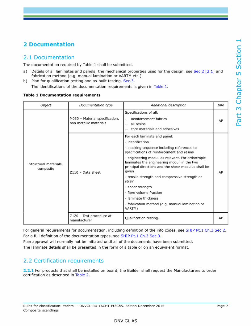
2.1 DocumentationThe documentation required by Table 1 shall be submitted.
a) Details of all laminates and panels: the mechanical properties used for the design, see Sec.2 [2.1] andfabrication method (e.g. manual lamination or VARTM etc.).
b) Plan for qualification testing and as-built testing, Sec.3.The identifications of the documentation requirements is given in Table 1.
Table 1 Documentation requirements
Object Documentation type Additional description Info
M030 – Material specification,non metallic materials
Specifications of all:
— Reinforcement fabrics— all resins— core materials and adhesives.
AP
Z110 – Data sheet
For each laminate and panel:
- identification.
- stacking sequence including references tospecifications of reinforcement and resins
- engineering moduli as relevant. For orthotropiclaminates the engineering moduli in the twoprincipal directions and the shear modulus shall begiven
- tensile strength and compressive strength orstrain
- shear strength
- fibre volume fraction
- laminate thickness
- fabrication method (e.g. manual lamination orVARTM)
AP
Structural materials,composite
Z120 – Test procedure atmanufacturer Qualification testing. AP
For general requirements for documentation, including definition of the info codes, see SHIP Pt.1 Ch.3 Sec.2.For a full definition of the documentation types, see SHIP Pt.1 Ch.3 Sec.3.Plan approval will normally not be initiated until all of the documents have been submitted.The laminate details shall be presented in the form of a table or on an equivalent format.
2.2 Certification requirements
2.2.1 For products that shall be installed on board, the Builder shall request the Manufacturers to ordercertification as described in Table 2.

Part
3 C
hapt
er 5
Sec
tion
1
Rules for classification: Yachts — DNVGL-RU-YACHT-Pt3Ch5. Edition December 2015 Page 8Composite scantlings
DNV GL AS
Table 2 Certification requirements
Object Certificate type Issued by Certification standard* Additional description
TA The SocietyStructural materials,composite
MC Manufacturer
Reinforcement,matrix, core materials,adhesives and coreadhesives
* Unless otherwise specified the certification standard is the rules.
For general certification requirements, see SHIP Pt.1 Ch.3 Sec.4.For a definition of the certification types, see SHIP Pt.1 Ch.1 Sec.4 and SHIP Pt.1 Ch.3 Sec.5.

Part
3 C
hapt
er 5
Sec
tion
2
Rules for classification: Yachts — DNVGL-RU-YACHT-Pt3Ch5. Edition December 2015 Page 9Composite scantlings
DNV GL AS
SECTION 2 MATERIALS
1 GeneralIn this section requirements regarding the application of structural materials as well as material protectionand material testing are given.
1.1 Laminating resins for hull, superstructure and deckhousesThe laminating resin (“matrix”) in hull and superstructure may be polyester, vinylester or epoxy. Other typesmay be accepted based on special consideration.When using polyester, Grade 1 polyester shall be used for the hull shell laminate in single skin constructionsand for the outer hull skin laminate in sandwich construction. For the inner skin laminate and superstructureGrade 2 polyester may be accepted. Specifications for Grade 1 and Grade 2 polyester resins are given inSHIP Pt.2 Ch.3 Sec.2 Table 11.
1.2 Surface coatingThe underwater part of the hull, the inside of tanks for liquids and other areas exposed to permanent liquidsubmergence shall have an efficient surface coating or lining, such as gelcoat, topcoat, an epoxy basedpainting or polyurethane of sufficient thickness. The surface lining of tanks is as far as practicable to be laidcontinuously in the tanks side and bottom.Weather exposed surfaces are to have a suitable surface coating.For inspection purposes the surface coating internally in the hull bottom and in tanks is wherever feasible tobe unpigmented.Where pigments are used, light colours should be used to expose damage and cracks more readily.
1.3 Mechanical properties
1.3.1 The mechanical properties of laminates depend on the properties of the constituent materials, fibresand matrix. It is however recognised that the mechanical properties of the laminates (in terms of meanstrength and variability) in the finished product to a significant degree also depend on the production processand the control of the same. Test data from purpose made test laminates may not be entirely representativefor the finished product. This is reflected in the specified Reserve Factors Sec.6 [7.2].
1.3.2 Sufficient control of the mechanical properties of the finished product shall be ensured by adhering tothe requirements to manufacturing and production facilities given in as specified int SHIP Pt.2 Ch.3 Sec.3Manufacturing and by verification through qualification testing and/or as-built testing as defined in [3].
2 Constituent materials
2.1 Material properties for structural design
2.1.1 The mechanical strength and moduli of laminates can either be determined by testing as prescribedin [3] or default values can be used as prescribed in Sec.6 [7]. When using default values testing is notrequired.The shear strength and modulus of core materials are to be specified and verified by testing in accordancewith the Society’s requirements for type approval for such materials. For core materials already typeapproved testing of the core material itself is not required, but the (msmv; manufacturer minimum specifiedvalue) values stated on the type approval certificate shall be used in design. Core materials for use in
Part
3 C
hapt
er 5
Sec
tion
2
Rules for classification: Yachts — DNVGL-RU-YACHT-Pt3Ch5. Edition December 2015 Page 10Composite scantlings
DNV GL AS
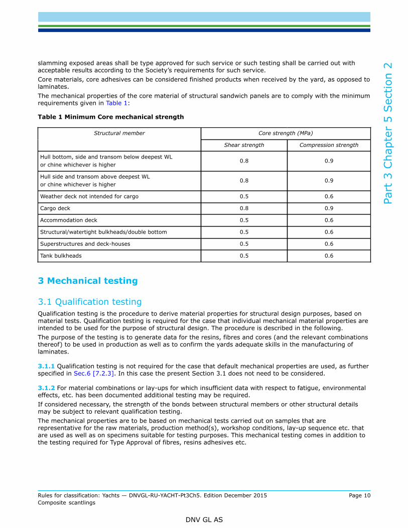
slamming exposed areas shall be type approved for such service or such testing shall be carried out withacceptable results according to the Society’s requirements for such service.Core materials, core adhesives can be considered finished products when received by the yard, as opposed tolaminates.The mechanical properties of the core material of structural sandwich panels are to comply with the minimumrequirements given in Table 1:
Table 1 Minimum Core mechanical strength
Core strength (MPa)Structural member
Shear strength Compression strength
Hull bottom, side and transom below deepest WLor chine whichever is higher
0.8 0.9
Hull side and transom above deepest WLor chine whichever is higher
0.8 0.9
Weather deck not intended for cargo 0.5 0.6
Cargo deck 0.8 0.9
Accommodation deck 0.5 0.6
Structural/watertight bulkheads/double bottom 0.5 0.6
Superstructures and deck-houses 0.5 0.6
Tank bulkheads 0.5 0.6
3 Mechanical testing
3.1 Qualification testingQualification testing is the procedure to derive material properties for structural design purposes, based onmaterial tests. Qualification testing is required for the case that individual mechanical material properties areintended to be used for the purpose of structural design. The procedure is described in the following.The purpose of the testing is to generate data for the resins, fibres and cores (and the relevant combinationsthereof) to be used in production as well as to confirm the yards adequate skills in the manufacturing oflaminates.
3.1.1 Qualification testing is not required for the case that default mechanical properties are used, as furtherspecified in Sec.6 [7.2.3]. In this case the present Section 3.1 does not need to be considered.
3.1.2 For material combinations or lay-ups for which insufficient data with respect to fatigue, environmentaleffects, etc. has been documented additional testing may be required.If considered necessary, the strength of the bonds between structural members or other structural detailsmay be subject to relevant qualification testing.The mechanical properties are to be based on mechanical tests carried out on samples that arerepresentative for the raw materials, production method(s), workshop conditions, lay-up sequence etc. thatare used as well as on specimens suitable for testing purposes. This mechanical testing comes in addition tothe testing required for Type Approval of fibres, resins adhesives etc.
Part
3 C
hapt
er 5
Sec
tion
2
Rules for classification: Yachts — DNVGL-RU-YACHT-Pt3Ch5. Edition December 2015 Page 11Composite scantlings
DNV GL AS
For well-known reinforcements and resin combinations and production methods the mechanical propertiesof laminates may be based on standard engineering analytical methods, such as micro mechanics, laminatetheory etc., substantiated by a reduced amount of testing.
3.1.3 The testing is the responsibility of the yard and shall normally be approved by the Society prior tocarrying out the design of the vessel. The yard shall submit a plan for testing for approval by the Societyprior to hull plans being approved. The plan for testing may invoke results from previous representative andwell documented testing. The test methods specified in [4] shall be used. The yard may use subcontractor(s)for testing.
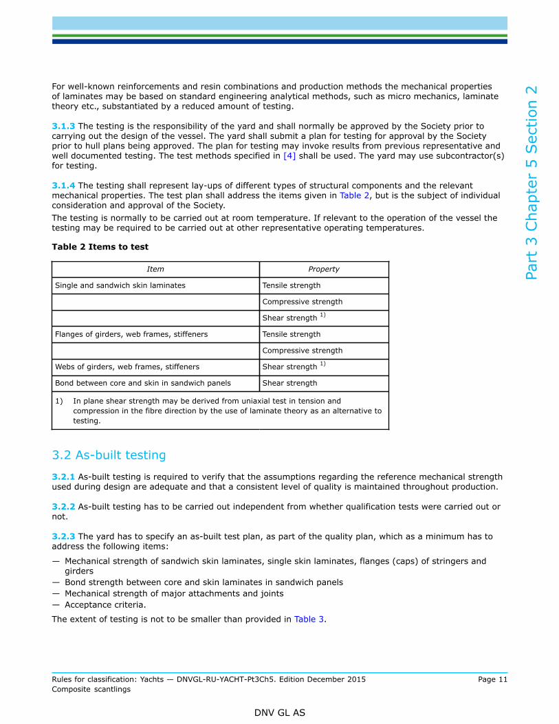
3.1.4 The testing shall represent lay-ups of different types of structural components and the relevantmechanical properties. The test plan shall address the items given in Table 2, but is the subject of individualconsideration and approval of the Society.The testing is normally to be carried out at room temperature. If relevant to the operation of the vessel thetesting may be required to be carried out at other representative operating temperatures.
Table 2 Items to test
Item Property
Single and sandwich skin laminates Tensile strength
Compressive strength
Shear strength 1)
Flanges of girders, web frames, stiffeners Tensile strength
Compressive strength
Webs of girders, web frames, stiffeners Shear strength 1)
Bond between core and skin in sandwich panels Shear strength
1) In plane shear strength may be derived from uniaxial test in tension andcompression in the fibre direction by the use of laminate theory as an alternative totesting.
3.2 As-built testing
3.2.1 As-built testing is required to verify that the assumptions regarding the reference mechanical strengthused during design are adequate and that a consistent level of quality is maintained throughout production.
3.2.2 As-built testing has to be carried out independent from whether qualification tests were carried out ornot.
3.2.3 The yard has to specify an as-built test plan, as part of the quality plan, which as a minimum has toaddress the following items:
— Mechanical strength of sandwich skin laminates, single skin laminates, flanges (caps) of stringers andgirders
— Bond strength between core and skin laminates in sandwich panels— Mechanical strength of major attachments and joints— Acceptance criteria.
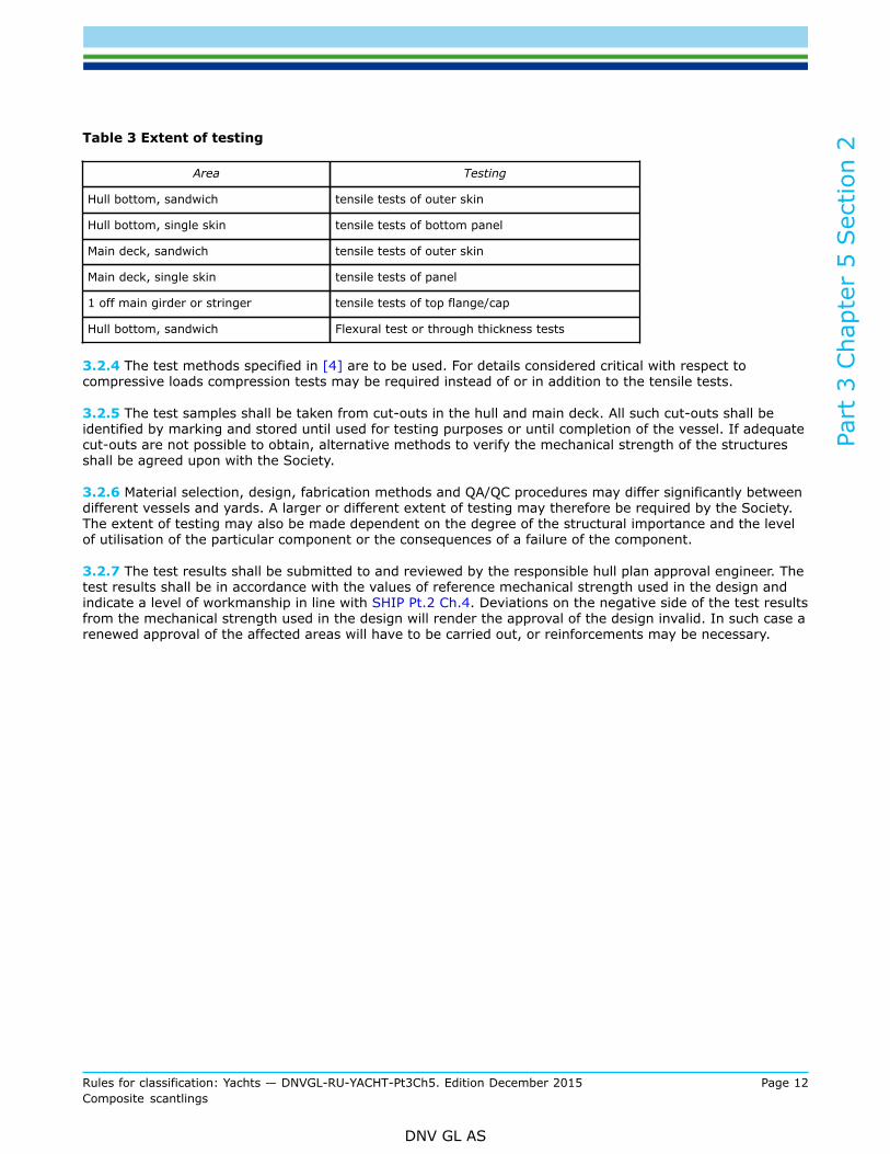
The extent of testing is not to be smaller than provided in Table 3.
Part
3 C
hapt
er 5
Sec
tion
2
Rules for classification: Yachts — DNVGL-RU-YACHT-Pt3Ch5. Edition December 2015 Page 12Composite scantlings
DNV GL AS
Table 3 Extent of testing
Area Testing
Hull bottom, sandwich tensile tests of outer skin
Hull bottom, single skin tensile tests of bottom panel
Main deck, sandwich tensile tests of outer skin
Main deck, single skin tensile tests of panel
1 off main girder or stringer tensile tests of top flange/cap
Hull bottom, sandwich Flexural test or through thickness tests
3.2.4 The test methods specified in [4] are to be used. For details considered critical with respect tocompressive loads compression tests may be required instead of or in addition to the tensile tests.
3.2.5 The test samples shall be taken from cut-outs in the hull and main deck. All such cut-outs shall beidentified by marking and stored until used for testing purposes or until completion of the vessel. If adequatecut-outs are not possible to obtain, alternative methods to verify the mechanical strength of the structuresshall be agreed upon with the Society.
3.2.6 Material selection, design, fabrication methods and QA/QC procedures may differ significantly betweendifferent vessels and yards. A larger or different extent of testing may therefore be required by the Society.The extent of testing may also be made dependent on the degree of the structural importance and the levelof utilisation of the particular component or the consequences of a failure of the component.
3.2.7 The test results shall be submitted to and reviewed by the responsible hull plan approval engineer. Thetest results shall be in accordance with the values of reference mechanical strength used in the design andindicate a level of workmanship in line with SHIP Pt.2 Ch.4. Deviations on the negative side of the test resultsfrom the mechanical strength used in the design will render the approval of the design invalid. In such case arenewed approval of the affected areas will have to be carried out, or reinforcements may be necessary.
Part
3 C
hapt
er 5
Sec
tion
2
Rules for classification: Yachts — DNVGL-RU-YACHT-Pt3Ch5. Edition December 2015 Page 13Composite scantlings
DNV GL AS
4 Testing procedures
4.1 Test standards
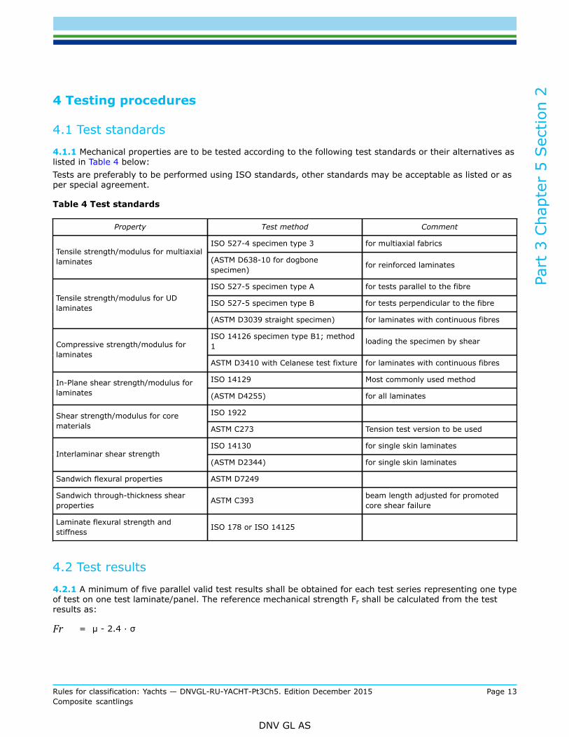
4.1.1 Mechanical properties are to be tested according to the following test standards or their alternatives aslisted in Table 4 below:Tests are preferably to be performed using ISO standards, other standards may be acceptable as listed or asper special agreement.
Table 4 Test standards
Property Test method Comment
ISO 527-4 specimen type 3 for multiaxial fabricsTensile strength/modulus for multiaxiallaminates (ASTM D638-10 for dogbone
specimen) for reinforced laminates
ISO 527-5 specimen type A for tests parallel to the fibre
ISO 527-5 specimen type B for tests perpendicular to the fibreTensile strength/modulus for UDlaminates
(ASTM D3039 straight specimen) for laminates with continuous fibres
ISO 14126 specimen type B1; method1 loading the specimen by shearCompressive strength/modulus for
laminatesASTM D3410 with Celanese test fixture for laminates with continuous fibres
ISO 14129 Most commonly used methodIn-Plane shear strength/modulus forlaminates (ASTM D4255) for all laminates
ISO 1922Shear strength/modulus for corematerials ASTM C273 Tension test version to be used
ISO 14130 for single skin laminatesInterlaminar shear strength
(ASTM D2344) for single skin laminates
Sandwich flexural properties ASTM D7249
Sandwich through-thickness shearproperties ASTM C393 beam length adjusted for promoted
core shear failure
Laminate flexural strength andstiffness ISO 178 or ISO 14125
4.2 Test results
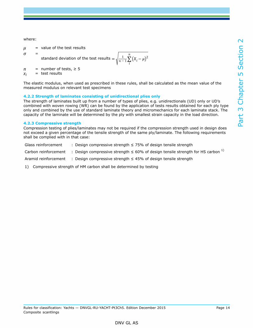
4.2.1 A minimum of five parallel valid test results shall be obtained for each test series representing one typeof test on one test laminate/panel. The reference mechanical strength Fr shall be calculated from the testresults as:
Fr = μ - 2.4 · σ
Part
3 C
hapt
er 5
Sec
tion
2
Rules for classification: Yachts — DNVGL-RU-YACHT-Pt3Ch5. Edition December 2015 Page 14Composite scantlings
DNV GL AS
where:
μ = value of the test resultsσ =
standard deviation of the test results
n = number of tests, ≥ 5xi = test results
The elastic modulus, when used as prescribed in these rules, shall be calculated as the mean value of themeasured modulus on relevant test specimens
4.2.2 Strength of laminates consisting of unidirectional plies onlyThe strength of laminates built up from a number of types of plies, e.g. unidirectionals (UD) only or UD’scombined with woven rowing (WR) can be found by the application of tests results obtained for each ply typeonly and combined by the use of standard laminate theory and micromechanics for each laminate stack. Thecapacity of the laminate will be determined by the ply with smallest strain capacity in the load direction.
4.2.3 Compressive strengthCompression testing of plies/laminates may not be required if the compression strength used in design doesnot exceed a given percentage of the tensile strength of the same ply/laminate. The following requirementsshall be complied with in that case:
Glass reinforcement : Design compressive strength ≤ 75% of design tensile strength
Carbon reinforcement : Design compressive strength ≤ 60% of design tensile strength for HS carbon 1)
Aramid reinforcement : Design compressive strength ≤ 45% of design tensile strength
1) Compressive strength of HM carbon shall be determined by testing
Part
3 C
hapt
er 5
Sec
tion
3
Rules for classification: Yachts — DNVGL-RU-YACHT-Pt3Ch5. Edition December 2015 Page 15Composite scantlings
DNV GL AS
SECTION 3 STRUCTURAL ARRANGEMENTS
1 General
1.1 Hierarchy of structures
1.1.1 The hull structural arrangement shall consist of an effective structural system of bulkheads, webframes, longitudinal girders, etc. as well as transverse and/or longitudinal frames or stiffeners. Longitudinalstiffeners are to be supported by transverse web frames or transverse bulkheads. Transverse frames are tobe supported by longitudinal girders or other longitudinal structural members.
1.1.2 Where bulkheads, bunks, shelves, or other structurally effective interior components are laminated tothe hull to provide structural support, they are to be adequately bonded.
1.2 Structural continuity
1.2.1 Care is to be taken to ensure structural continuity and to avoid sharp corners and abrupt changes insection and shape.
1.3 Access
1.3.1 Access for visual routine inspection of structures shall be possible for all essential structural elementsrelated to global strength, water and weathertight integrity, keel attachment, chain plates and rudder supportstructures.In case of a damage inspection it can be acceptable that access will be possible only after more intrusiveoperation.Compartements without possible access through hatches or similar are not acceptable, except whencompletely filled with buoyancy foam.
1.4 Bulkheads
1.4.1 The number and location of transverse watertight bulkheads are to be in accordance with therequirements for the ship type notation in question.
1.4.2 Bulkheads are to be arranged and designed to cope with global and local strength requirements. Theyare to carry, transfer and distribute lateral design loads on hull and deck, pick up reaction forces from girdersand carry sufficient stress compensation relief around cut-outs.
1.5 Superstructure and deckhouses
1.5.1 In superstructures and deckhouses, the front bulkhead is to be in line with a transverse bulkhead inthe hull below or be supported by a combination of girders and pillars. The after end bulkhead is also to beeffectively supported. As far as practicable, exposed sides and internal longitudinal and transverse bulkheadsare to be located above girders and frames in the hull structure and are to be in line in the various tiers ofaccommodation. Where such structural arrangement in line is not possible, there is to be other effectivesupport.
1.5.2 Sufficient transverse strength is to be provided by means of transverse bulkheads or girder and webframe structures.

Part
3 C
hapt
er 5
Sec
tion
3
Rules for classification: Yachts — DNVGL-RU-YACHT-Pt3Ch5. Edition December 2015 Page 16Composite scantlings
DNV GL AS
1.5.3 At the break of superstructures, which have not set-in from the ship’s side, the side plating is toextend beyond the ends of the superstructure, and is to be gradually reduced in height down to the deck orbulwark. The transition is to be smooth and without local discontinuities.
1.5.4 In long deckhouses, openings in the sides are to have well rounded corners. The perimeter of anyopening (with a hatch, door or window) shall be able to support the specified load corresponding to the areaof the opening and adjoining panels.
Part
3 C
hapt
er 5
Sec
tion
4
Rules for classification: Yachts — DNVGL-RU-YACHT-Pt3Ch5. Edition December 2015 Page 17Composite scantlings
DNV GL AS
SECTION 4 PRINCIPLES OF STRUCTURAL DESIGN ANDCALCULATION
1 General
1.1 CompositesFRP exhibits close to linear behaviour to failure as long as the response is fibre dominated and shows littleor no yielding behaviour before failure. Consequently, special attention is needed in structural design, e.g. inconnection with stress concentrations.Through thickness strength is smaller by orders of magnitude than in plane strength. Although it is arequirement that loads shall coincide to a large degree with fibre directions, through thickness stresscannot always be avoided completely and shall be handled in a conservative way. Delamination caused byoverloading, impact or deficient design is an important cause of subsequent failure and contributor to fatiguefailure.Not all parts are suitable for FRP. Complex 3-dimensional stress states may make the use of other materialsnecessary.
1.2 Principles of laminate lay-up
1.2.1 The design of the vessel is to be based on mechanical properties that are representative for the rawmaterials, production method(s), workshop conditions, lay-up sequence etc. that are used.
1.2.2 The vessel shall be designed such that the load(s) are carried mainly by the fibres. The fibres shall bealigned close to the direction(s) of the main load path(s).
1.2.3 Preferably laminates shall be homogeneous, symmetrical and balanced. If not, due attention shall begiven to possible secondary effects.
1.2.4 The failure mechanism of a laminate shall be fibre failure. Matrix failure shall be controlled by havingfibres in a sufficient number of directions and by a stacking sequence avoiding fibre clusters. Groups of plieswith the same fibre direction shall not exceed 1.5 mm in thickness.Deviations may be accepted in local areas of details that are well proven and for minor loads of secondarynature.
1.2.5 Significant through thickness tensile load in laminates and sandwich panels shall be avoided as faras possible. Although no specific scantling requirements are given in these rules the Society may requiremodifications to designs where the combination of the magnitude of the through thickness loads and theconsequence of a failure is considered unacceptable by the Society.Laminates exposed to through thickness compressive loads shall be designed with the same reserve factor asspecified elsewhere for laminates in these rules.
1.2.6 Unlike metallic constructions, joints between different structural FRP elements may present challengeswhen ensuring structural continuity, e.g. through bulkheads. Special consideration to the continuity of plies ofload carrying fibres shall be given.
1.3 Minimum areal weight of reinforcement
1.3.1 Minimum requirement to the weight of reinforcement in single skin and sandwich laminates are givenin Sec.7 [2]. These minimum requirements apply also if scantling requirements indicate the need for a lowerweight.
Part
3 C
hapt
er 5
Sec
tion
4
Rules for classification: Yachts — DNVGL-RU-YACHT-Pt3Ch5. Edition December 2015 Page 18Composite scantlings
DNV GL AS
The intention of these minimum requirements is to provide a reasonable resistance to wear, tear andlocal impact. Deviations from these minimum requirements may be accepted for exposed surfaces if suchresistance is provided by other means. Such deviations are the subject of agreement by the Society.
2 Failure criteria
2.1 Failure criteria - laminates
2.1.1 The default failure criterion for laminates is maximum strain in the fibre direction. Load effects andallowables are expressed as strain in the fibre direction. This is based on the requirements given in [1.1]being fulfilled.Ultimate stress may alternatively be used as failure criterion in accordance with [2.5].
2.1.2 Other recognized laminate failure criteria may be used, e.g. Tsai-Wu or Puck. The use of such criteriarequires more material data than fibre strain to failure. Such data shall be determined by material testingaccording to the principle prescribed in Sec.2 [3],Sec.2 [4] shall be applied; alternatively conservativeassumptions shall be used.An acceptable modification of the Tsai-Wu criterion for verifying fibre maximum strain criterion is given inDNV GL-OS-C501.The use of other failure criteria is subject to approval by the Society.
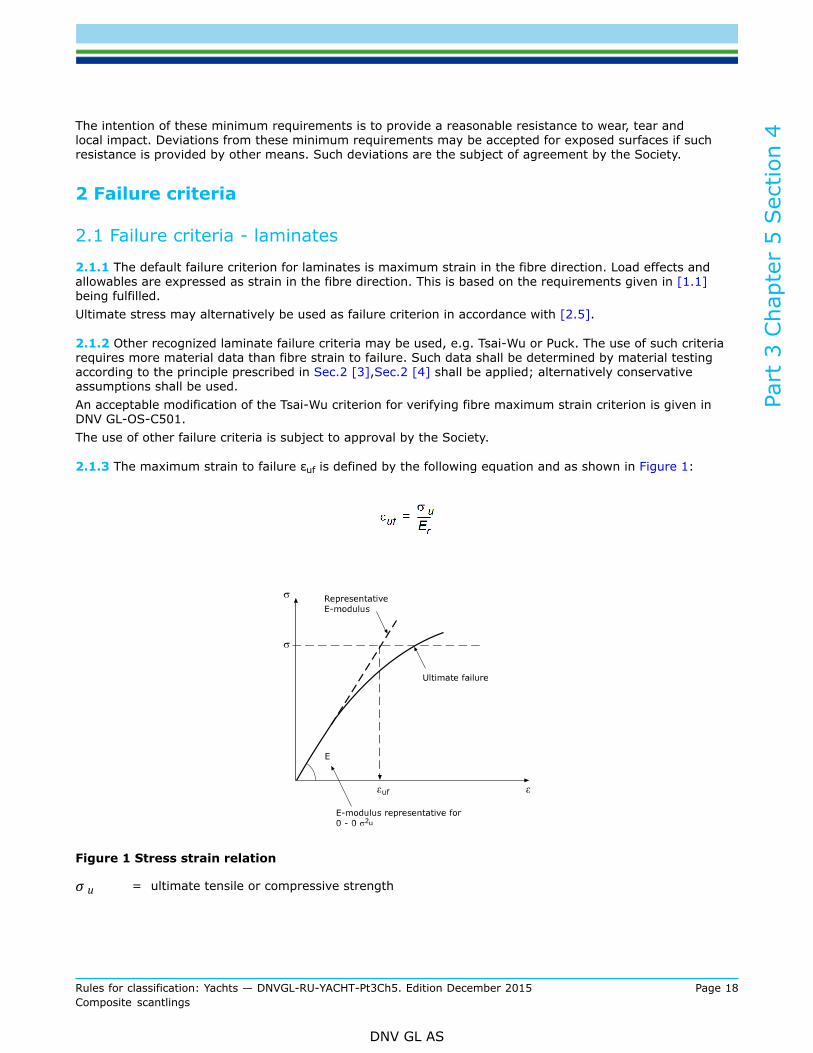
2.1.3 The maximum strain to failure εuf is defined by the following equation and as shown in Figure 1:
Figure 1 Stress strain relation
σ u = ultimate tensile or compressive strength
Part
3 C
hapt
er 5
Sec
tion
4
Rules for classification: Yachts — DNVGL-RU-YACHT-Pt3Ch5. Edition December 2015 Page 19Composite scantlings
DNV GL AS
Er = representative E modulus for the laminate in the range of allowable stresses (see Sec.6)The representative modulus is defined as secant modulus at 0.3 σ u determined either bymeasurements or by laminate theory.
Guidance note:In most cases the E modulus as defined in ISO 527-4 and ISO527-5 will qualify as “representative E modulus”
---e-n-d---of---g-u-i-d-a-n-c-e---n-o-t-e---
2.1.4 The reference mechanical strength Fr in terms of strain to failure can either be determined by testingas prescribed in Sec.2 [3]or by using default values prescribed in Sec.6 [7].Mixing of default values and values determined by testing is subject to approval by the Society.
2.2 Failure criteria – core materials
2.2.1 The failure criteria for core materials are maximum core shear stress and compressive stress.
2.3 Failure criteria – bonds
2.3.1 The failure criterion for laminated bonds and adhesive bonds is bond-line shear stress.
2.4 Failure criteria – stability
2.4.1 Failure criteria with respect to stability are given in Sec.6 [7].
2.5 Failure criteria - ultimate stress
2.5.1 Scantlings calculations can also be carried out based on stress instead of strain when laminates arehomogeneous through the thickness. Based on the linear relation between stress and strain prescribed in[2.2.1] strain can be converted to stress based on recognized engineering methods or test results on theactual laminates can be used (rule of mixtures for individual plies and laminate theory). Any approximationshall provide results on the conservative side.
Guidance note:Ultimate stress may be a practical failure criterion when strength data is available in terms of stress only.
---e-n-d---of---g-u-i-d-a-n-c-e---n-o-t-e---
3 Scantling calculation methods
3.1 General
3.1.1 Composites are usually stacked in a certain order to achieve certain properties. This includes balancinga laminate for certain properties or introducing a light weight core as a middle layer between two skinlaminates.Analyses may be based on the stiffness of the laminate or panel expressed as engineering moduli, or strainsmay be determined from laminate/panel line loads and line moments via the complete stiffness matrix (ABDmatrix). Both approaches are acceptable as prescribed in the rules.
3.1.2 Scantlings can be determined by the use of the formulas given in the Sec.6, or by direct calculation orby FEA according [3.3], observing the limitations prescribed in the rules.
Part
3 C
hapt
er 5
Sec
tion
4
Rules for classification: Yachts — DNVGL-RU-YACHT-Pt3Ch5. Edition December 2015 Page 20Composite scantlings
DNV GL AS
3.1.3 Safety factors are specified Sec.6 [7].
3.2 Rule formulas
3.2.1 Rule formulas for the calculation of fibre strain for loaded panels and stiffeners/frames/girders basedon engineering laminate moduli are given in Sec.6.
3.2.2 Alternatively to the rule formulas, fibre strain can be calculated directly from laminate line loads andmoments using laminate theory (the full stiffness matrix). The same methods as prescribed in Sec.6 shall beused for calculating laminate line loads and moments from the design loads.
3.2.3 Rule formulas given for direct calculation of scantlings for panels, stiffeners, girders etc. apply toapproximately orthogonal structural arrangements with a clear hierarchy of structural members. Where thisconditions is not fulfilled more comprehensive investigations will be necessary, e.g. grillage analyses.
3.3 Finite Element Analysis (FEA)
3.3.1 FEA can be used for structural analysis of particular detailed designs, of subassemblies (e.g. todetermine plate reactions for non-rectangular shapes, uneven pressure distribution, varying scantlings, etc.)or for global strength of the complete hull and/or superstructure. The load cases prescribed in Ch.3 shall beused as relevant for the particular analyses, as well as other relevant loads.
3.3.2 FEA may be carried out using non-linear geometry, except where proscribed elsewhere in the rules.FEA may not be carried out using non-linear material properties, except based on special agreement with theSociety. LPF analysis based on up-dating of the stiffness matrix is acceptable.
3.3.3 Failure criteria shall be as prescribed in [2]. Allowable strains/stresses and safety factors shall be thesame as when the rule formulas are used.
Guidance note:Software and FEA postprocessors using e.g. Tsai-Wu generate results for first ply failure (FPF) if no updating of the stiffness matrixis carried out. The use of FPF is acceptable. If LPF shall be invoked, the method for assessing FPF based on the analyses resultsshall be agreed upon with the Society.
---e-n-d---of---g-u-i-d-a-n-c-e---n-o-t-e---
3.3.4 Geometrically non-linear effects for the analysis of structural response of laterally loaded convexcurved panels, i.e. where the curvature of the panel is towards the laterally loaded side may not be takeninto account when combined with the load cases specified in the rules except as specified in Sec.6.
3.3.5 Global strength analysis using FEA may be challenging with respect to the defining appropriate supportconditions, balancing of the FE model and the application of the loads. This may result in a global loaddistribution differing from the rules values. Thus, results obtained by this analysis need to be scaled to theloads prescribed in Ch.3.
Guidance note:DNV GL Class Note 31.8 Direct Strength Analysis of Hull Structures in Passenger Ships provide recommendations for the modellingand execution of FEA with respect to global strength.
---e-n-d---of---g-u-i-d-a-n-c-e---n-o-t-e---
Part
3 C
hapt
er 5
Sec
tion
5
Rules for classification: Yachts — DNVGL-RU-YACHT-Pt3Ch5. Edition December 2015 Page 21Composite scantlings
DNV GL AS
SECTION 5 HULL GIRDER (GLOBAL) STRENGTH
1 General
1.1 Introduction
1.1.1 The assessment of the global strength shall, in addition to laminate in-plane strength, also account forbuckling capacity of plates and girders/stiffeners under compressive and shear load.
Guidance note:When hulls and decks are constructed using sandwich plating, the structural material subject to global loads is often much less thanfor single skin hulls, making global strength more critical.
---e-n-d---of---g-u-i-d-a-n-c-e---n-o-t-e---
2 Hull girder global loads
2.1 Introduction
2.1.1 Global loads are considered loads acting on the hull without the consideration of local load introduction.For slender monohulls, relevant global loads are global vertical shear force and global vertical bendingmoment. Others (global torque, global transverse shear force, global transverse bending) are relevant to alower degree and/or for unusual configurations.
2.1.2 Global loads are generally considered to arise through:
— sea loads— accelerations— gravitational loads— others, unspecified (e.g. crane or rig attachments).
2.2 Load cases
2.2.1 Load cases and load definitions to be used for hull girder strength analysis of composite vessels arespecified in Ch.3.
Part
3 C
hapt
er 5
Sec
tion
5
Rules for classification: Yachts — DNVGL-RU-YACHT-Pt3Ch5. Edition December 2015 Page 22Composite scantlings
DNV GL AS
3 Structural assessment
3.1 Generic section analysis
3.1.1 The expression “hull girder” implies that the hull structure will be modelled as a single beam(monohulls) or a grillage of beams (multi-hulls). This will be followed by a generic section analysis whichincludes the review of the global strength capacity of 2-dimensional beam cross sections.This is provided the structure allows for such simplification. Should there be doubts, it is preferred to applymethods as described in [3.2].
Guidance note:A sufficient number of potential critical sections need to be analysed to identify the critical ones. For this purpose it will be requiredto determine the 2D beam cross section stiffness characteristics:
— EI (for bending analysis),
— GA (for shear analysis)
— GJ (for torque analysis)
— EA (for uniaxial compression/tension)
for the individual hull sections. Only this way, the individual ply, layer, material and orientation characteristics are reflectedappropriately within one cross section.
---e-n-d---of---g-u-i-d-a-n-c-e---n-o-t-e---
3.1.2 Only effective parts of a section may be accounted for when calculating the section properties. Thisimplies including only structures which are structurally continuous through and on either side of the crosssection over a length long enough to ensure effective force transfer.
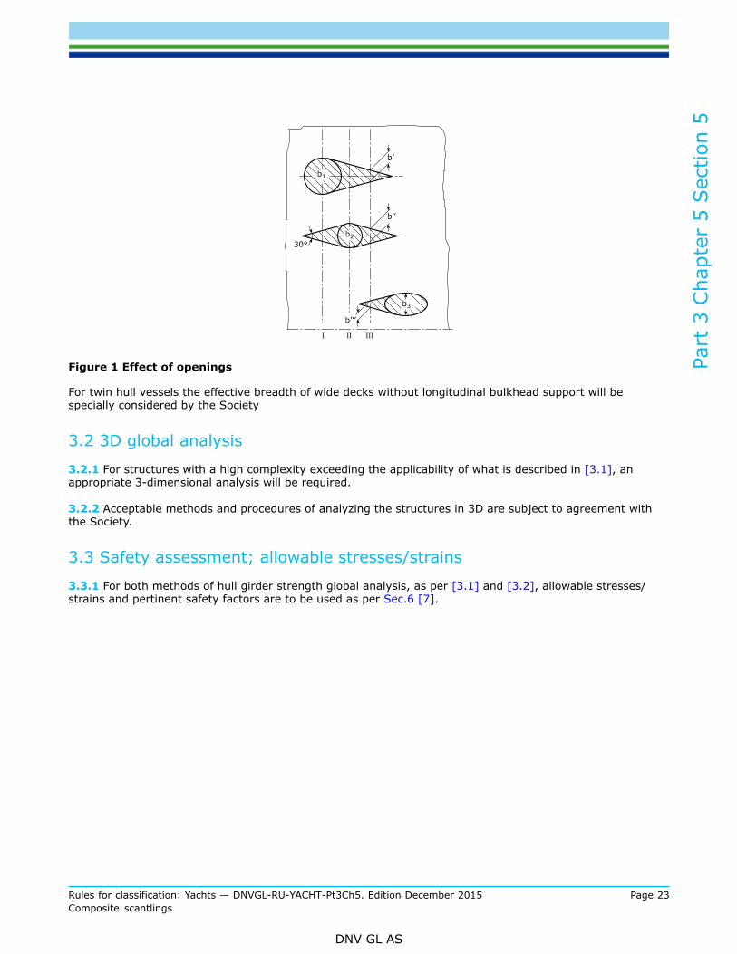
3.1.3 Openings and cut-outs in structures relevant to global strength calculations are to be treated withutmost diligence as they do not only affect the individual section analysed but possibly also neighbouringsections. This “shadow effect” is however very much depending on the load type (bending/uniaxial loador shear and torque) and also on the laminate type. A generic shadow to assume in case quasi-isotropicstructures are subjected to bending or uniaxial tension/compression, is shown in Figure 1: The effective areato account for in proximity of openings and cut-outs of openings is assumed to be reduced by the shadedareas in Figure 1, i.e. inside tangents at an angle of 30° to each other. Example for transverse section III:
bIII = b' + b'' + b'''
Part
3 C
hapt
er 5
Sec
tion
5
Rules for classification: Yachts — DNVGL-RU-YACHT-Pt3Ch5. Edition December 2015 Page 23Composite scantlings
DNV GL AS
Figure 1 Effect of openings
For twin hull vessels the effective breadth of wide decks without longitudinal bulkhead support will bespecially considered by the Society
3.2 3D global analysis
3.2.1 For structures with a high complexity exceeding the applicability of what is described in [3.1], anappropriate 3-dimensional analysis will be required.
3.2.2 Acceptable methods and procedures of analyzing the structures in 3D are subject to agreement withthe Society.
3.3 Safety assessment; allowable stresses/strains
3.3.1 For both methods of hull girder strength global analysis, as per [3.1] and [3.2], allowable stresses/strains and pertinent safety factors are to be used as per Sec.6 [7].

Part
3 C
hapt
er 5
Sec
tion
6
Rules for classification: Yachts — DNVGL-RU-YACHT-Pt3Ch5. Edition December 2015 Page 24Composite scantlings
DNV GL AS
SECTION 6 SCANTLINGS
1 General
1.1 Introduction
1.1.1 The definition of scantling requirements in this section are to be applied in conjunction with therelevant load cases defined in Ch.3 provisions for materials SHIP Pt.2 Ch.4 and the previous and followingsections of this chapter. In combination they provide a distinct level of structural reliability.This generic approach of deriving scantling requirements is based mainly on the application of the ClassicalLaminate Theory (“CLT”); the determination of the structural response is based on beam and panel theoryand finally the maximum stress and strain concept as the failure criteria.
1.1.2 The provisions in this section are based on a geometrical structural arrangement which featuresorthogonal structures with a certain structural hierarchy.
1.1.3 The methodology given in this section is presented in successive order.
1.1.4 If not explicitly mentioned, consistent unit variables are to be used.
1.1.5 Alternative methods, e.g. FEA, for deriving scantlings to the method presented in this section are givenin Sec.4 [3] Scantling calculation methods. Such methods may be necessary or favourable for structuresin which a clear structural hierarchy as assumed in [1.1.2] is not present, e.g. grids, or not having anorthogonal lay-out. FEA may also be the preferred option by the designer.
2 Elasto-mechanical properties of FRPs
2.1 General
2.1.1 The purpose of this item is to provide methodologies for deriving elasto-mechanical properties of FRPwhich are required and of primary importance for the ongoing analysis for obtaining scantlings in [3] through[7] of this Section.
2.2 Nomenclature2.2.1 Denotations:ψ = Mass content of reinforcing material in a laminateφ = Volume content of reinforcement material in a laminateE11 = Young’s modulus of a single ply with unidirectional fibres, parallel to fibresE22 = Young’s modulus of a single ply with unidirectional fibres, perpendicular to fibresn12, n21= Poisson’s ratios of a single plyG12 = Shear modulus of a single plyρf = Specific gravity of fibre materialρm = Specific gravity of matrix materialEfL = Young’s modulus of fibre in fibre directionEfT = Young’s modulus of fibre transverse to fibre directionEm = Young’s modulus of matrixνf12 = Poisson’s ratio of fibreνm = Poisson’s ratio of resinGm = Shear modulus of the matrixGf = Shear modulus of the fibre
Part
3 C
hapt
er 5
Sec
tion
6
Rules for classification: Yachts — DNVGL-RU-YACHT-Pt3Ch5. Edition December 2015 Page 25Composite scantlings
DNV GL AS
Ex = Young’s modulus of a ply, multiply or laminate in x-direction of global laminate coordinatesystem
Ey = Young’s modulus of a ply, multiply or laminate in y-direction of global laminate coordinatesystem
Gxy = Shear modulus of a ply, multiply or laminate in xy-direction of global laminate co-ordinatesystem
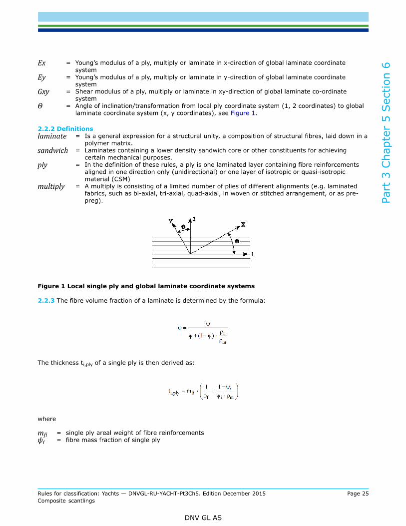
Θ = Angle of inclination/transformation from local ply coordinate system (1, 2 coordinates) to globallaminate coordinate system (x, y coordinates), see Figure 1.
2.2.2 Definitionslaminate = Is a general expression for a structural unity, a composition of structural fibres, laid down in a
polymer matrix.sandwich = Laminates containing a lower density sandwich core or other constituents for achieving
certain mechanical purposes.ply = In the definition of these rules, a ply is one laminated layer containing fibre reinforcements
aligned in one direction only (unidirectional) or one layer of isotropic or quasi-isotropicmaterial (CSM)
multiply = A multiply is consisting of a limited number of plies of different alignments (e.g. laminatedfabrics, such as bi-axial, tri-axial, quad-axial, in woven or stitched arrangement, or as pre-preg).
Figure 1 Local single ply and global laminate coordinate systems
2.2.3 The fibre volume fraction of a laminate is determined by the formula:
The thickness ti,ply of a single ply is then derived as:
where
mfi = single ply areal weight of fibre reinforcementsψi = fibre mass fraction of single ply
Part
3 C
hapt
er 5
Sec
tion
6
Rules for classification: Yachts — DNVGL-RU-YACHT-Pt3Ch5. Edition December 2015 Page 26Composite scantlings
DNV GL AS
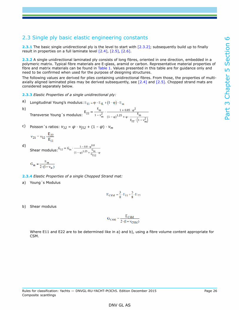
2.3 Single ply basic elastic engineering constants
2.3.1 The basic single unidirectional ply is the level to start with [2.3.2]; subsequently build up to finallyresult in properties on a full laminate level [2.4], [2.5], [2.6].
2.3.2 A single unidirectional laminated ply consists of long fibres, oriented in one direction, embedded in apolymeric matrix. Typical fibre materials are E-glass, aramid or carbon. Representative material properties offibre and matrix materials can be found in Table 1. Values presented in this table are for guidance only andneed to be confirmed when used for the purpose of designing structures.The following values are derived for plies containing unidirectional fibres. From those, the properties of multi-axially aligned laminated plies may be derived subsequently, see [2.4] and [2.5]. Chopped strand mats areconsidered separately below.
2.3.3 Elastic Properties of a single unidirectional ply:
a) Longitudinal Young’s modulus:
b)
Transverse Young´s modulus:
c) Poisson´s ratios: ν12 = φ · νf12 + (1 – φ) · νm
d)Shear modulus:
2.3.4 Elastic Properties of a single Chopped Strand mat:
a) Young´s Modulus
b) Shear modulus
Where E11 and E22 are to be determined like in a) and b), using a fibre volume content appropriate forCSM.

Part
3 C
hapt
er 5
Sec
tion
6
Rules for classification: Yachts — DNVGL-RU-YACHT-Pt3Ch5. Edition December 2015 Page 27Composite scantlings
DNV GL AS
Table 1 Generic constituent material properties
Fibres Matrices
E-Glass Aramid HS Carbon HM Carbon Polyester Epoxy
Specific gravity [g/m3] 2.54 1.45 1.77 1.9 1.2 1.2
parallel tofibres MPa 73000 130000 230000 370000
Young´sModulus perpendicular
to fibres MPa 73000 5400 14000 9000
3000 3600
Shear Modulus MPa 30000 12000 23000 20000 1140 1330
Poisson´s ratio - 0.18 0.35 0.27 0.23 0.316 0.35
2.4 Single ply stiffness properties
2.4.1 The representative stiffness properties for a single ply that is part of a multiply fabric, a laminate or asandwich laminate is derived in three steps.Firstly the stiffness matrix Q will be computed for each ply from its engineering constants in the localcoordinate system [2.4.1].In a second step, the stiffness matrix Q will be transformed to the global coordinate system, resulting in thetransformed stiffness matrix Q´ [2.4.2].From this, the engineering constants of each ply in the global laminate coordinate system will be determinedin a third step [2.5].
Single UD ply stiffness matrix in local coordinate system2.4.2 The components of the stiffness matrix Q are determined for a unidirectional laminated ply as follows:
Stiffness matrix components Q for chopped strand mat (CSM) are to be derived using the above equations,too, where:E11 = E22 = ECSM
ν12 = ν21 = 0.28
Part
3 C
hapt
er 5
Sec
tion
6
Rules for classification: Yachts — DNVGL-RU-YACHT-Pt3Ch5. Edition December 2015 Page 28Composite scantlings
DNV GL AS
G12 = GCSM
Stiffness matrix components Q for cores of a sandwich laminate are to be derived using the above equations,too, using the materials mechanical properties:
E11 = Ex ; E22= Ey ; ν12 ; ν21 ; G12
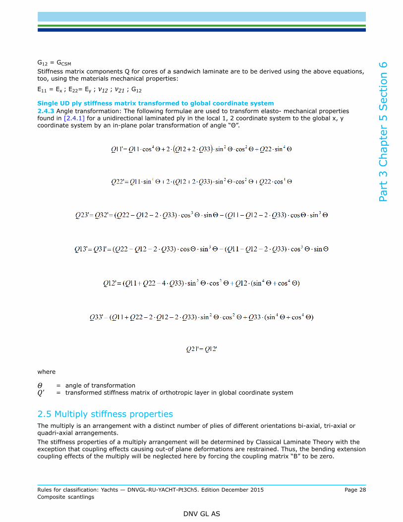
Single UD ply stiffness matrix transformed to global coordinate system2.4.3 Angle transformation: The following formulae are used to transform elasto- mechanical propertiesfound in [2.4.1] for a unidirectional laminated ply in the local 1, 2 coordinate system to the global x, ycoordinate system by an in-plane polar transformation of angle “Θ”.
where
Θ = angle of transformationQ’ = transformed stiffness matrix of orthotropic layer in global coordinate system
2.5 Multiply stiffness propertiesThe multiply is an arrangement with a distinct number of plies of different orientations bi-axial, tri-axial orquadri-axial arrangements.The stiffness properties of a multiply arrangement will be determined by Classical Laminate Theory with theexception that coupling effects causing out-of plane deformations are restrained. Thus, the bending extensioncoupling effects of the multiply will be neglected here by forcing the coupling matrix “B” to be zero.
Part
3 C
hapt
er 5
Sec
tion
6
Rules for classification: Yachts — DNVGL-RU-YACHT-Pt3Ch5. Edition December 2015 Page 29Composite scantlings
DNV GL AS
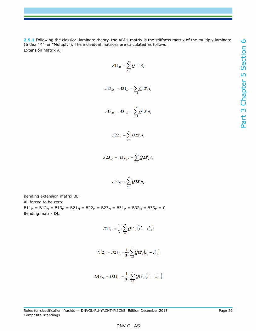
2.5.1 Following the classical laminate theory, the ABDL matrix is the stiffness matrix of the multiply laminate(Index “M” for “Multiply”). The individual matrices are calculated as follows:Extension matrix AL:
Bending extension matrix BL:All forced to be zero:B11M = B12M = B13M = B21M = B22M = B23M = B31M = B32M = B33M = 0Bending matrix DL:
Part
3 C
hapt
er 5
Sec
tion
6
Rules for classification: Yachts — DNVGL-RU-YACHT-Pt3Ch5. Edition December 2015 Page 30Composite scantlings
DNV GL AS
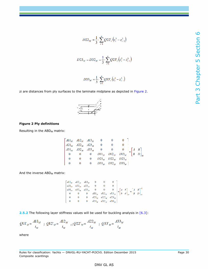
zi are distances from ply surfaces to the laminate midplane as depicted in Figure 2.
Figure 2 Ply definitions
Resulting in the ABDM matrix:
And the inverse ABDM matrix:
2.5.2 The following layer stiffness values will be used for buckling analysis in [6.3]:
; ,; ;
where
Part
3 C
hapt
er 5
Sec
tion
6
Rules for classification: Yachts — DNVGL-RU-YACHT-Pt3Ch5. Edition December 2015 Page 31Composite scantlings
DNV GL AS
tM = thickness of a multiply
2.6 Laminate stiffness properties (including sandwich)
2.6.1 Depending on the structural functionality of a laminate, different stiffness characteristics will berelevant for the further analysis of the structural response on applied load.These typical stiffness characteristics are:
— Tensile/compressive stiffness— Flexural stiffness— In-plane shear stiffness
and can be described either by the use of the engineering constants for moduli, E*A, E*I or G*A, or alsothe relevant components of the ABDM matrix. It is depending on the demands, which of those alternativestiffness properties will be sophisticated/ effective in analysis and use.
2.6.2 In-plane engineering constantsIn-plane engineering constants (through-thickness averaged) of a single skin laminate or a completesandwich laminate (index “L” for Laminate”) with individual stacking sequence and global x,y coordinatesystem, provided that the full laminate is considered being one multiply:
; ; ;
2.6.3 In-plane stiffness propertiesIn-plane stiffness properties (shear, tension, compression) of a single skin laminate or a complete sandwichlaminate with individual stacking sequence is determined by the extension matrix [A]L=[A]M, provided thatthe full laminate is considered being one multiply.
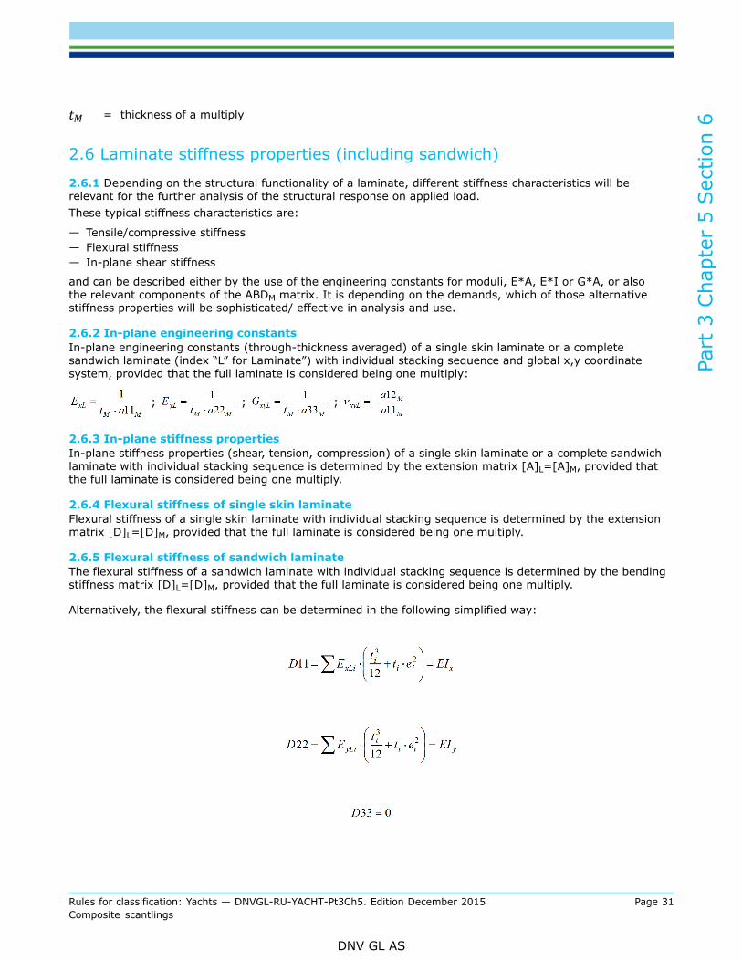
2.6.4 Flexural stiffness of single skin laminateFlexural stiffness of a single skin laminate with individual stacking sequence is determined by the extensionmatrix [D]L=[D]M, provided that the full laminate is considered being one multiply.
2.6.5 Flexural stiffness of sandwich laminateThe flexural stiffness of a sandwich laminate with individual stacking sequence is determined by the bendingstiffness matrix [D]L=[D]M, provided that the full laminate is considered being one multiply.
Alternatively, the flexural stiffness can be determined in the following simplified way:

Part
3 C
hapt
er 5
Sec
tion
6
Rules for classification: Yachts — DNVGL-RU-YACHT-Pt3Ch5. Edition December 2015 Page 32Composite scantlings
DNV GL AS
ExLi/yLi = Young´s modulus of sandwich layer “i” in relevant directionti = thickness of layer “i”ei = distance of layer “i”centroid from neutral axis of sandwich
3 Laterally loaded plates
3.1 Introduction, applicability
3.1.1 In the following, structural design requirements for laterally loaded shells and plates are given.Lateral loading is usually caused by static or dynamic sea or water pressure (slamming) of hull shells, decks,superstructure, watertight bulkheads, tank walls, etc.
3.1.2 The methodology presented in the following is covering flat or slightly curved panels of generallysquare or rectangular geometry with different boundary conditions under uniform lateral load. Othergeometries (e.g. triangular or trapezoid styled) or load distributions require an equivalent approach.
3.1.3 It is recommended that elasto-mechanical properties of inner and outer sandwich skin do not differsignificantly. This is to avoid secondary effects, such as superimposed twist or bending of plates. Should thisbe the case, individual treatment is required.The following approaches are featuring the ideas and the background of the “plate theory”. Membrane effectsoccurring due to curved shells are treated with a linear reduction coefficient.
3.1.4 The objective is to determine plate stresses and strains from bending moments and shear forcescaused by lateral pressure. The problem of an all-side supported panel will effectively be reduced to a unitbeam strip, by using appropriate coefficients. The evaluation of stresses/strains is focusing on the spot wherethe maximum bending stress/strain occurs and a spot where the maximum through-thickness shear stress/strain occurs. Further to that, a correction is incorporated to allow the use of orthotropic material and plateproperties and the application to sandwich construction.
3.1.5 If not explicitly mentioned, unit consistent variables are to be used.
3.2 Plate parameters
3.2.1 Laminated plates are to be characterized by the following parameters:
3.2.2 Structural parametersTc = thickness of sandwich coreZi = distance from a certain location to the neutral axis
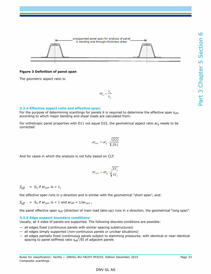
3.2.3 Geometrical parametersThe unsupported panel span is in general to be measured between the effective centres of the supportingmembers, as indicated in Figure 3 below. The unsupported span can be taken as the inside distance betweenthe stiffneners provided the desing pressure is calculated based on the same span (applicable to bottomslamming loads).
sx = unsupported span in global x-directionsy = unsupported span in global y-direction
Part
3 C
hapt
er 5
Sec
tion
6
Rules for classification: Yachts — DNVGL-RU-YACHT-Pt3Ch5. Edition December 2015 Page 33Composite scantlings
DNV GL AS
Figure 3 Definition of panel span
The geometric aspect ratio is:
3.2.4 Effective aspect ratio and effective span:For the purpose of determining scantlings for panels it is required to determine the effective span seff,according to which major bending and shear loads are calculated from:
For orthotropic panel properties with D11 not equal D22, the geometrical aspect ratio arg needs to becorrected:
And for cases in which the analysis is not fully based on CLT:
Seff = Sy if arcorr is > 1,
the effective span runs in y-direction and is similar with the geometrical “short span”, and:
Seff = Sx if arcorr is < 1 and areff = 1/arcorr ,
the panel effective span seff (direction of main load take-up) runs in x-direction, the geometrical “long span”.
3.2.5 Edge support boundary conditions:Usually, all 4 sides of panels are supported. The following discrete conditions are possible:
— all edges fixed (continuous panels with similar spacing substructures)— all edges simply supported (non-continuous panels or unclear situations)— all edges partially fixed (continuous panels subject to slamming pressures; with identical or near identical
spacing to panel stiffness ratio seff2/EI of adjacent panels

Part
3 C
hapt
er 5
Sec
tion
6
Rules for classification: Yachts — DNVGL-RU-YACHT-Pt3Ch5. Edition December 2015 Page 34Composite scantlings
DNV GL AS
The choice depends on geometrical and structural situations and can be refined using appropriatemethodologies, subject to agreement by the Society.The relevant coefficients are provided in Table 2 and are processed within items [3.3.5], [3.3.6] and [3.3.7].
3.2.6 Alternate Boundaries, corrected span; “hard chines”:In specific cases, hull chines or other sudden changes in geometry may be considered being a boundary aswell. Should a chine be considered presenting one edge of a panel, the angle of the chine ω shall be close to90° to allow for such assumption, see Figure 4. Should the angle be greater than 90°, the panel span takenfor panel calculations needs to be increased virtually, using the characteristic correction factors describedbelow.Boundary conditions as per normal panel analysis can be chosen.The panel span which is delimited by a chine has to be multiplied by the correction factor cs:
Figure 4 Corrected span
Figure 5 Panel span correction factor cs dependant on chine angle
This correction is particularly applicable for equidistant spacing of panels, i.e. for panels on both sides ofvessel’s chined centerline without the existence of a centerline girder, e.g. where the panels are delimited byoff-centre longitudinals. For determination of cs see Figure 5.
Part
3 C
hapt
er 5
Sec
tion
6
Rules for classification: Yachts — DNVGL-RU-YACHT-Pt3Ch5. Edition December 2015 Page 35Composite scantlings
DNV GL AS
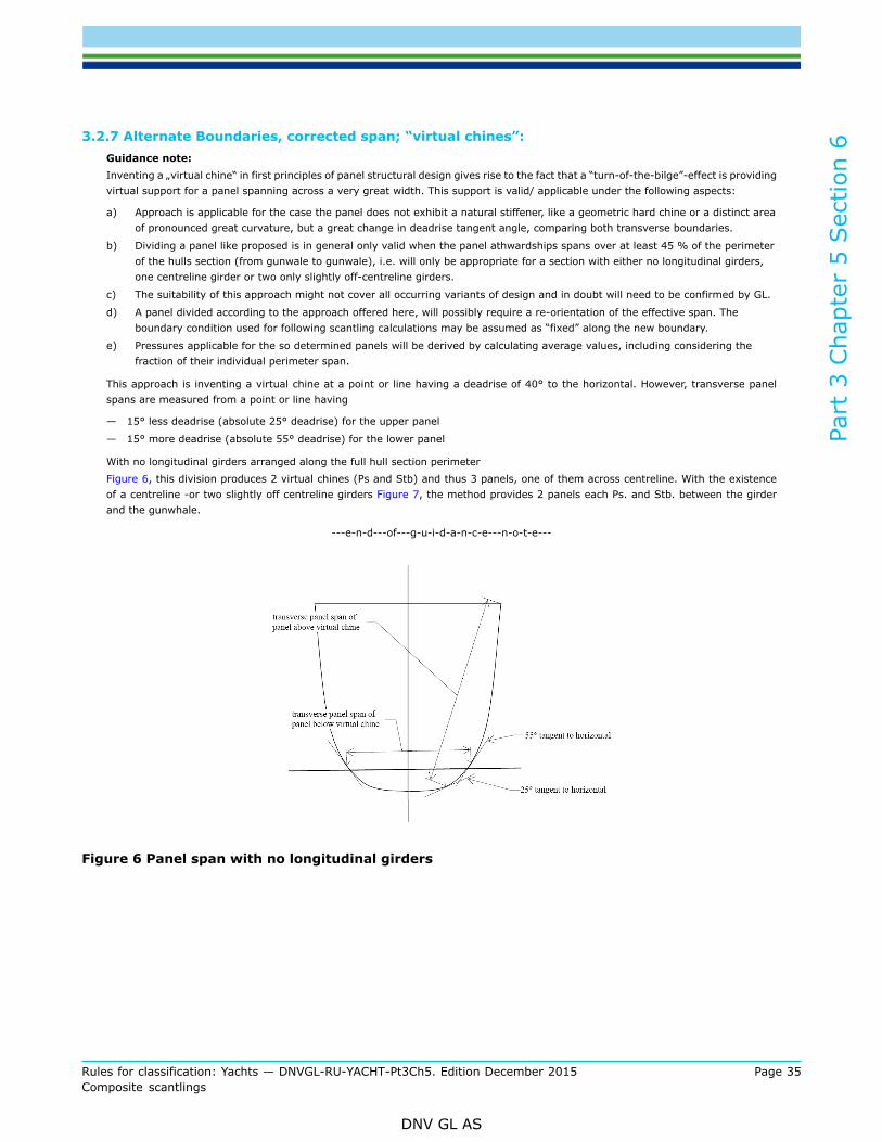
3.2.7 Alternate Boundaries, corrected span; “virtual chines”:Guidance note:Inventing a „virtual chine“ in first principles of panel structural design gives rise to the fact that a “turn-of-the-bilge”-effect is providingvirtual support for a panel spanning across a very great width. This support is valid/ applicable under the following aspects:
a) Approach is applicable for the case the panel does not exhibit a natural stiffener, like a geometric hard chine or a distinct areaof pronounced great curvature, but a great change in deadrise tangent angle, comparing both transverse boundaries.
b) Dividing a panel like proposed is in general only valid when the panel athwardships spans over at least 45 % of the perimeterof the hulls section (from gunwale to gunwale), i.e. will only be appropriate for a section with either no longitudinal girders,one centreline girder or two only slightly off-centreline girders.
c) The suitability of this approach might not cover all occurring variants of design and in doubt will need to be confirmed by GL.
d) A panel divided according to the approach offered here, will possibly require a re-orientation of the effective span. Theboundary condition used for following scantling calculations may be assumed as “fixed” along the new boundary.
e) Pressures applicable for the so determined panels will be derived by calculating average values, including considering thefraction of their individual perimeter span.
This approach is inventing a virtual chine at a point or line having a deadrise of 40° to the horizontal. However, transverse panelspans are measured from a point or line having
— 15° less deadrise (absolute 25° deadrise) for the upper panel
— 15° more deadrise (absolute 55° deadrise) for the lower panel
With no longitudinal girders arranged along the full hull section perimeterFigure 6, this division produces 2 virtual chines (Ps and Stb) and thus 3 panels, one of them across centreline. With the existenceof a centreline -or two slightly off centreline girders Figure 7, the method provides 2 panels each Ps. and Stb. between the girderand the gunwhale.
---e-n-d---of---g-u-i-d-a-n-c-e---n-o-t-e---
Figure 6 Panel span with no longitudinal girders

Part
3 C
hapt
er 5
Sec
tion
6
Rules for classification: Yachts — DNVGL-RU-YACHT-Pt3Ch5. Edition December 2015 Page 36Composite scantlings
DNV GL AS
Figure 7 Panel span with existence of longitudinal girder
3.2.8 Curvature reduction:Curvature will only be considered if the plate is curved in the direction of the effective span seff, see Figure 8.
Plate curvature correction coefficient:
where:
and:
rc,min = 0.65
Figure 8 Plate curvature
Part
3 C
hapt
er 5
Sec
tion
6
Rules for classification: Yachts — DNVGL-RU-YACHT-Pt3Ch5. Edition December 2015 Page 37Composite scantlings
DNV GL AS
3.3 Plate reactions
3.3.1 In the following, methodologies are provided for the case that sandwich and single skin panels haveconsistent scantlings and uniform lateral pressure across their area. Should this not be the case, reactionsare to be determined for additional locations other than those described in [3.3.5], [3.3.6] and [3.3.7].Loading of a panel other than a uniform pressure requires an equivalent or separate approach..Restrictions, limitations and assumptions of this methodology are described in [3.1].
3.3.2 For single skin panels, membrane effects may be included if the panel has sufficient in-plane supportalong all edges. In such a case a detailed analysis shall be carried out taking properly into account the in-plane and bending stiffness of the panel, the rotational stiffness and stiffness in the plane of the panel of thesupporting stiffeners/girders and the adjoining panels. The analysis shall be detailed enough to quantify allstress concentrations along the panel edges.
3.3.3 The plate reactions determined in this item/paragraph are basis for further evaluation in [5].
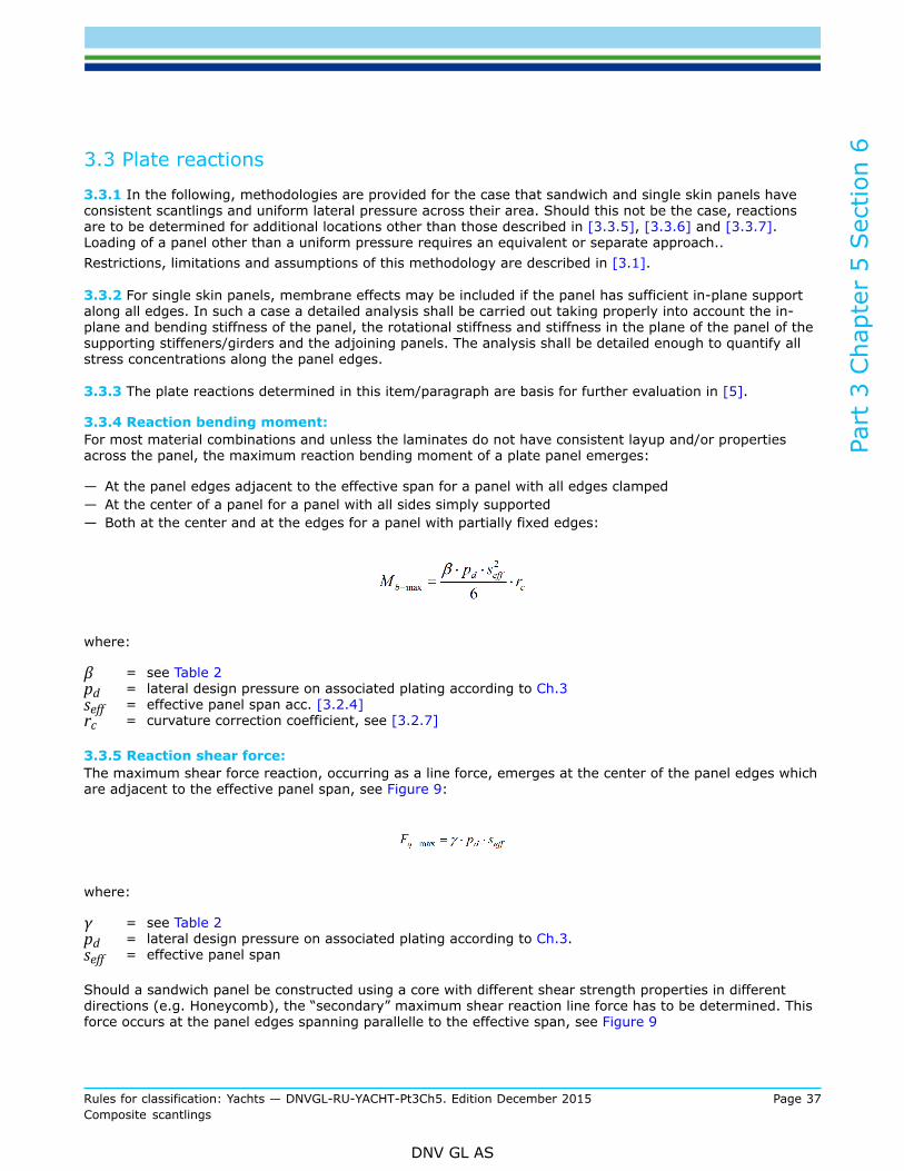
3.3.4 Reaction bending moment:For most material combinations and unless the laminates do not have consistent layup and/or propertiesacross the panel, the maximum reaction bending moment of a plate panel emerges:
— At the panel edges adjacent to the effective span for a panel with all edges clamped— At the center of a panel for a panel with all sides simply supported— Both at the center and at the edges for a panel with partially fixed edges:
where:
β = see Table 2pd = lateral design pressure on associated plating according to Ch.3seff = effective panel span acc. [3.2.4]rc = curvature correction coefficient, see [3.2.7]
3.3.5 Reaction shear force:The maximum shear force reaction, occurring as a line force, emerges at the center of the panel edges whichare adjacent to the effective panel span, see Figure 9:
where:
γ = see Table 2pd = lateral design pressure on associated plating according to Ch.3.seff = effective panel span
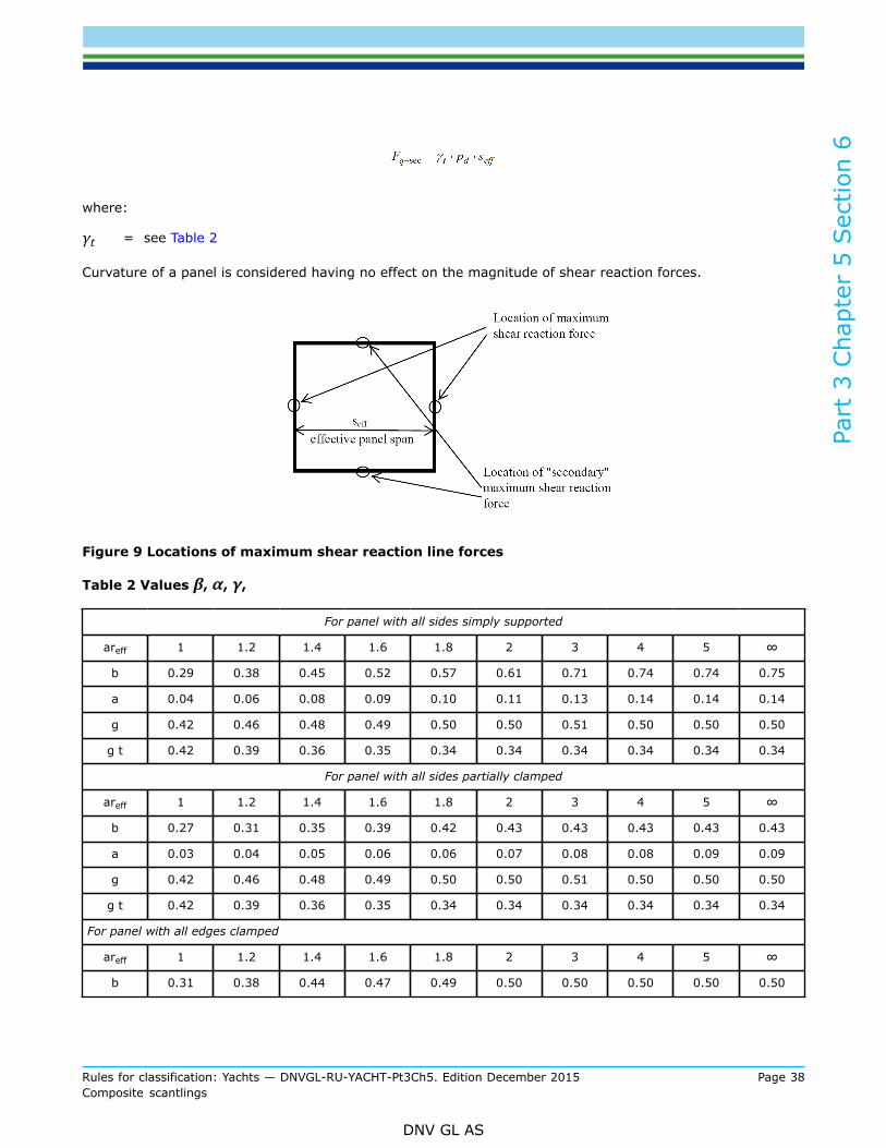
Should a sandwich panel be constructed using a core with different shear strength properties in differentdirections (e.g. Honeycomb), the “secondary” maximum shear reaction line force has to be determined. Thisforce occurs at the panel edges spanning parallelle to the effective span, see Figure 9
Part
3 C
hapt
er 5
Sec
tion
6
Rules for classification: Yachts — DNVGL-RU-YACHT-Pt3Ch5. Edition December 2015 Page 38Composite scantlings
DNV GL AS
where:
γt = see Table 2
Curvature of a panel is considered having no effect on the magnitude of shear reaction forces.
Figure 9 Locations of maximum shear reaction line forces
Table 2 Values β, α, γ,
For panel with all sides simply supported
areff 1 1.2 1.4 1.6 1.8 2 3 4 5 ∞
b 0.29 0.38 0.45 0.52 0.57 0.61 0.71 0.74 0.74 0.75
a 0.04 0.06 0.08 0.09 0.10 0.11 0.13 0.14 0.14 0.14
g 0.42 0.46 0.48 0.49 0.50 0.50 0.51 0.50 0.50 0.50
g t 0.42 0.39 0.36 0.35 0.34 0.34 0.34 0.34 0.34 0.34
For panel with all sides partially clamped
areff 1 1.2 1.4 1.6 1.8 2 3 4 5 ∞
b 0.27 0.31 0.35 0.39 0.42 0.43 0.43 0.43 0.43 0.43
a 0.03 0.04 0.05 0.06 0.06 0.07 0.08 0.08 0.09 0.09
g 0.42 0.46 0.48 0.49 0.50 0.50 0.51 0.50 0.50 0.50
g t 0.42 0.39 0.36 0.35 0.34 0.34 0.34 0.34 0.34 0.34
For panel with all edges clamped
areff 1 1.2 1.4 1.6 1.8 2 3 4 5 ∞
b 0.31 0.38 0.44 0.47 0.49 0.50 0.50 0.50 0.50 0.50
Part
3 C
hapt
er 5
Sec
tion
6
Rules for classification: Yachts — DNVGL-RU-YACHT-Pt3Ch5. Edition December 2015 Page 39Composite scantlings
DNV GL AS
a 0.01 0.02 0.02 0.03 0.03 0.03 0.03 0.03 0.03 0.03
g 0.42 0.46 0.48 0.49 0.50 0.50 0.50 0.50 0.50 0.50
g t 0.42 0.39 0.36 0.35 0.34 0.34 0.34 0.34 0.34 0.34
4 Laterally loaded beams
4.1 Introduction, applicability
4.1.1 The following approach can be used for laterally loaded beams; stiffeners, frames and girders, with orwithout associated plating attached. These structural members are usually part of an orthogonal structuralsystem of a vessel. In well found cases, curvature effects may be taken into account in a similar way asshown for panels, see Figure 8.
4.1.2 Typically, beams consist of one or more webs designed to carry the shear force and flanges to carry thebending load. One flange is usually comprised by a certain amount of attached plating (see effective width)and possible additional pads beneath the web. The other flange is comprised by the “capping” of the beam.
4.1.3 Beams should be designed in a way that the transfer of loads is fibre dominant. In general this willrequire shear webs to include fibre in the +/- 45° direction, whereas the flanges consist dominantly of 0°plies. It shall be ensured that shear loads are transferred efficiently to the flange and plating.
4.1.4 The following approaches are featuring the partly simplified “Classical Laminate Theory” and the simple“Beam Theory”.The objective is to determine beam stresses and strains from bending moments and shear forces causedby lateral pressure on the associated plating. The analytical model is presented by a simple beam withappropriate support conditions.
4.1.5 In case the scantlings and loads are constant over the full length of the beam, it is sufficient toevaluate stresses and strains, respectively, through:
— bending moment and shear force at the end of the beam for a support condition “ends clamped”— bending moment at the center of the beam and shear effects at the end of the beam for a support
condition “ends simply supported”— bending moment at the center and end of the beam and shear effects at the end of the beam for a
support condition “one end clamped and one end simply supported”
Should scantlings and/or loading not be constant or uniform along the beam, bending moments and shearforces need to be determined individually and more locations than indicated above will be required to beanalysed.
4.1.6 It is recommended to use symmetrical or near-symmetrical section shapes (symmetry axis normal tothe lateral pressure plane, i.e. plating), as unsymmetrical shapes are subjected to superimposed secondaryeffects such as transverse bending or a twisting of the beam (flange). This makes a more refined analysisnecessary than offered below.
4.1.7 The following assumptions imply that the beams perform “plane bending”, i.e. that the neutral axis ofthe beam with associated plating is parallel to the axis about which the assembly bends; the beam assemblyis symmetrical about the axis normal to the plating.

Part
3 C
hapt
er 5
Sec
tion
6
Rules for classification: Yachts — DNVGL-RU-YACHT-Pt3Ch5. Edition December 2015 Page 40Composite scantlings
DNV GL AS
4.2 Beam parameters
4.2.1 A beam is composed of a plurality of different functional elements, most often:
— web— flange— attached plating
4.2.2 Structural parameters:
a) Flexural stiffness:
where:
Ei = Young´s modulus of element i, according to [2.6.2].a)Ii = specific moment of inertia of elementei = distance of element’s centroid from neutral axis of assemblySi = cross sectional area of element
b) Shear stiffness:
For determining the shear stiffness of a beam assembly, usually only the shear webs are accounted for.
where:
ti = web thicknesshi = depth of web measured perpendicular to associated plating, see Figure 12Gi = in-plane shear modulus of element i, according to [2.6.2].a)
4.2.3 Geometrical parameters:l = unsupported length of the beams = stiffener or girder spacing as per (Ch.3)
4.2.4 Effective width of platingDefinitions
The expression “effective width” or “effective flange” is used to describe the effect in which a stiffener or agirder mounted on a large panel receives some contribution in a way the panel acts as a “lower” flange to thestiffener.
The method can be adopted for single skin as well as for sandwich panels.
The method is for beams with a constant lateral load, but can be used with reasonable accuracy also forbeams with single point load(s). Other load scenarios are subject to agreement by the Society.
Part
3 C
hapt
er 5
Sec
tion
6
Rules for classification: Yachts — DNVGL-RU-YACHT-Pt3Ch5. Edition December 2015 Page 41Composite scantlings
DNV GL AS
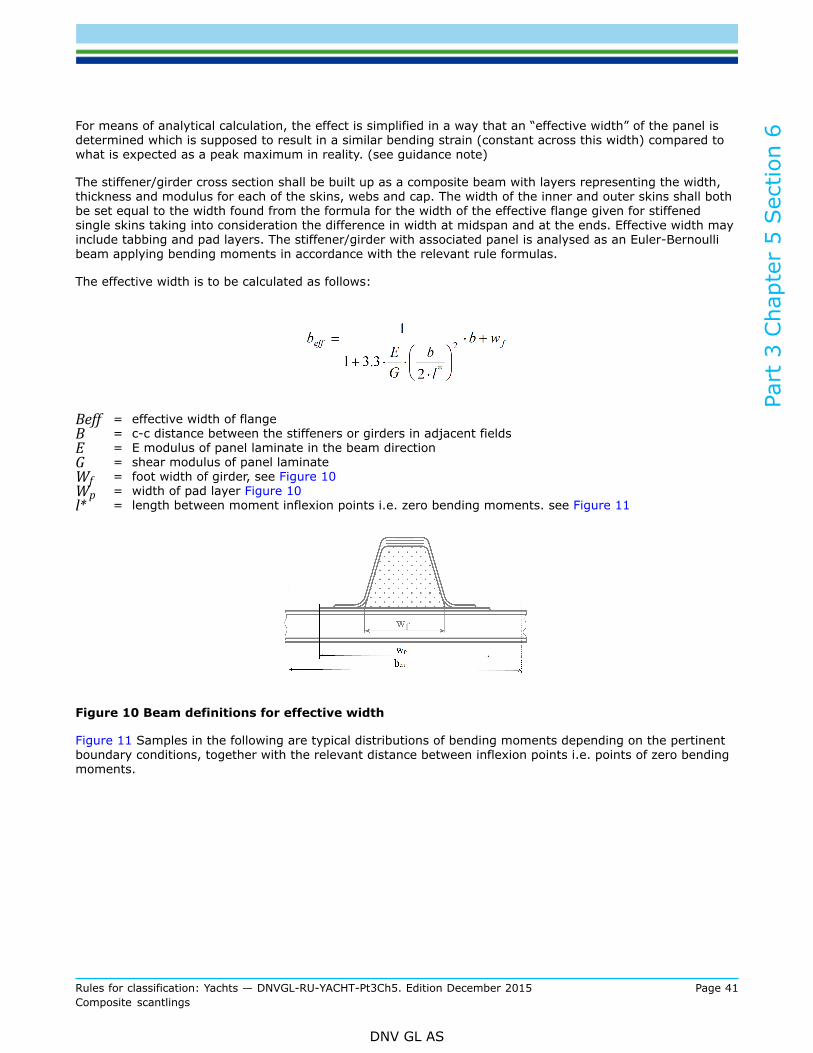
For means of analytical calculation, the effect is simplified in a way that an “effective width” of the panel isdetermined which is supposed to result in a similar bending strain (constant across this width) compared towhat is expected as a peak maximum in reality. (see guidance note)
The stiffener/girder cross section shall be built up as a composite beam with layers representing the width,thickness and modulus for each of the skins, webs and cap. The width of the inner and outer skins shall bothbe set equal to the width found from the formula for the width of the effective flange given for stiffenedsingle skins taking into consideration the difference in width at midspan and at the ends. Effective width mayinclude tabbing and pad layers. The stiffener/girder with associated panel is analysed as an Euler-Bernoullibeam applying bending moments in accordance with the relevant rule formulas.
The effective width is to be calculated as follows:
Beff = effective width of flangeB = c-c distance between the stiffeners or girders in adjacent fieldsE = E modulus of panel laminate in the beam directionG = shear modulus of panel laminateWf = foot width of girder, see Figure 10Wp = width of pad layer Figure 10l* = length between moment inflexion points i.e. zero bending moments. see Figure 11
Figure 10 Beam definitions for effective width
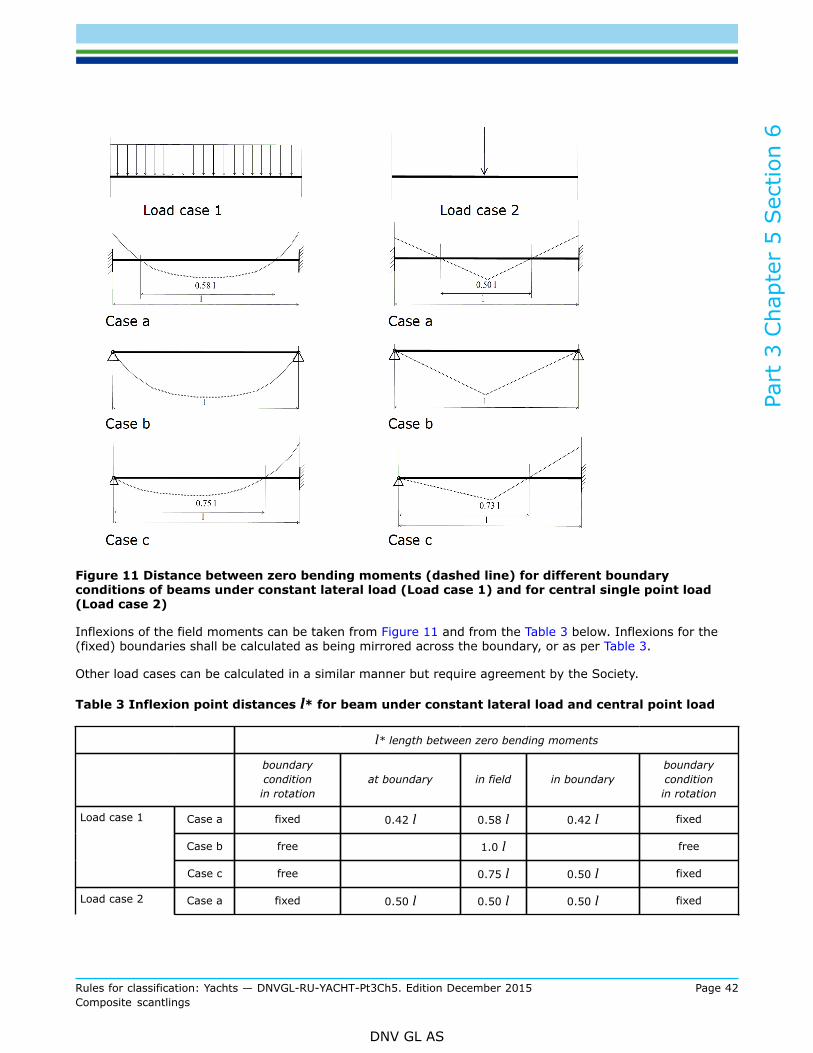
Figure 11 Samples in the following are typical distributions of bending moments depending on the pertinentboundary conditions, together with the relevant distance between inflexion points i.e. points of zero bendingmoments.
Part
3 C
hapt
er 5
Sec
tion
6
Rules for classification: Yachts — DNVGL-RU-YACHT-Pt3Ch5. Edition December 2015 Page 42Composite scantlings
DNV GL AS
Figure 11 Distance between zero bending moments (dashed line) for different boundaryconditions of beams under constant lateral load (Load case 1) and for central single point load(Load case 2)
Inflexions of the field moments can be taken from Figure 11 and from the Table 3 below. Inflexions for the(fixed) boundaries shall be calculated as being mirrored across the boundary, or as per Table 3.
Other load cases can be calculated in a similar manner but require agreement by the Society.
Table 3 Inflexion point distances l* for beam under constant lateral load and central point load
l* length between zero bending moments
boundaryconditionin rotation
at boundary in field in boundaryboundaryconditionin rotation
Case a fixed 0.42 l 0.58 l 0.42 l fixed
Case b free 1.0 l free
Load case 1
Case c free 0.75 l 0.50 l fixed
Load case 2 Case a fixed 0.50 l 0.50 l 0.50 l fixed

Part
3 C
hapt
er 5
Sec
tion
6
Rules for classification: Yachts — DNVGL-RU-YACHT-Pt3Ch5. Edition December 2015 Page 43Composite scantlings
DNV GL AS
l* length between zero bending moments
boundaryconditionin rotation
at boundary in field in boundaryboundaryconditionin rotation
Case b free 1.0 l free
Case c free 0.73 l 0.54 l fixed
Guidance note:This approach does not constitute a stringent and correct analysis of such beams on sandwich panels. The underlying assumption ofthe beam responding as an Euler-Bernoulli beam is not correct, to a smaller or lesser degree, and the assumption of equal width ofthe effective flanges of the inner skin and outer skin is not correct. However, this approach is acceptable to the Society as a simplifiedapproximate method as it has been found to give acceptable results on the conservative side by comparison with results from FEAanalyses of a number of sandwich/stiffener configurations.Alternative methods:The strain level in sandwich panels with associated stiffeners/girders loaded by a lateral pressure can be determined either by a FEAof a representative model or by using the approximate approach.
---e-n-d---of---g-u-i-d-a-n-c-e---n-o-t-e---
4.2.5 Beam depthWhere beams are inclined towards the attached plating, see Figure 12, the inclination shall be consideredin an appropriate way when calculating the scantlings. Usually the web of a beam is contributing to thefull depth of the beam, where the bending stiffness shall account only for a structural height as measuredperpendicular to the attached plating.
Figure 12 Inclined stringer
The calculated effective width shall not be taken greater than the load width.
4.2.6 Edge support boundary conditions:The following discrete conditions are possible:
Part
3 C
hapt
er 5
Sec
tion
6
Rules for classification: Yachts — DNVGL-RU-YACHT-Pt3Ch5. Edition December 2015 Page 44Composite scantlings
DNV GL AS
— Both ends fixed (continuous beams with similar l2/EI of adjacent beams)— Both ends simply supported (non-continuous beams or unclear situations)— One end fixed, one end simply supported— Ends partially fixed upon special considerations (continuous beams subject to slamming pressures; with
identical or near-identical effective length to beam stiffness ratio l2/EI of adjacent beams
The choice depends on geometrical and structural situations and can be refined using appropriatemethodologies, subject to agreement by the Society. The relevant coefficients are given and processed withinitems [4.3]
4.2.7 Curvature correction:
where:
0.03 < h/l < 0.1
and:
rcb,min = 0.65
Figure 13 Beam curvature definitions
4.3 Beam reactions
4.3.1 In the following, methodologies are provided for the case that beams have consistent scantlings anduniform load along their length. Should this not be the case, reactions are to be determined for locationsother than those described in [4.1.5].Restrictions, limitations and assumptions of this methodology are described in [4.1].Beam reactions may have to be determined by FEA, particularly for:
a) orthogonal girder systems with beams of similar stiffness, i.e. to determine grillage effectsb) non-constant lateral pressurec) arying scantlings along beam
The plate reactions determined in this item/paragraph are basis for further evaluation in [7].
4.3.2 Reaction bending moment:For most material combinations and unless the beam does not have consistent layup and/or properties alongits span, the maximum reaction bending moment of a beam emerges:

Part
3 C
hapt
er 5
Sec
tion
6
Rules for classification: Yachts — DNVGL-RU-YACHT-Pt3Ch5. Edition December 2015 Page 45Composite scantlings
DNV GL AS
— at the ends with both ends clamped— at the center of a beam with all ends simply supported— at the clamped end when one side is simply supported and other end is clamped
where:
pd = lateral design pressure on associated plating according to Ch.3.w = load widthℓ = length of beam between supportsrcb = beam curvature correction coefficient acc. [4.2.6]cb = boundary condition coefficient
= 12 for fixed end supports, used for continuous girders, similar length= 8 for ends simply supported, used for non-continuous girders= 8 for one end simply supported and other end fixed, used where relevant= 18 at ends for continuous beams subjected to slamming see [4.2.4]= 14 at midspan for continuous beams subjected to slamming see [4.2.4]
4.3.3 Reaction shear force:The maximum shear force typically occurs at the boundaries. For symmetrical boundary conditions themaximum shear force is:
where:
pd = see Ch.3ℓ = see [4.2.2]w = see [4.2.2]cb = boundary condition coefficient
1for both ends with similar support condition= 1.25 for clamped end of beam with one side clamped and one side simply supported= 0.75 for simply supported end of beam with one side clamped and one side simply supported
5 Structural response, load effectsThe following paragraph provides a methodology for the assessment of stresses and strains within laterallyloaded structures.
5.1 Panels5.1.1 Laminate strains of solid or sandwich laminatesThe structural performance of a laterally loaded plate is characterized by the occurring strains in the laminateusing the following approach.
The following matrix is combining the inverse stiffness matrix and the load matrix:

Part
3 C
hapt
er 5
Sec
tion
6
Rules for classification: Yachts — DNVGL-RU-YACHT-Pt3Ch5. Edition December 2015 Page 46Composite scantlings
DNV GL AS
where:
exo, ey0, gxy0 = the resulting strains only from in-plane forces Nx, Ny, and Nxy; tension, compression andin-plane shear.
kx, ky, kxy = the warpings only from bending moments Mx, My, and Mxy
Overall individual strains in a laminate from a combined loading can be determined:
where:
Zi = location of interest; distance from laminate geometrical mid-plane (not neutral axis!) desired strain
The maximum strains through bending moments usually emerge at the outer surfaces of a composite. Hence,for evaluating the maximum strains, use the maximum distances from the mid-plane at each side of theplate, see Figure 2.
Alternatively, the strain in the fibre direction in individual plies can be determined directly from Nx, Ny,Nxy,Mx, My, and Mxy via laminate theory.
The calculated strains in a laminate or in the fibre direction in an individual ply shall not exceed the allowablestrains defined in [7].
5.1.2 Shear stresses of sandwich core from shear forces:Whereas with solid coreless laminates, the through-thickness interlaminar stress is rarely a design criterion,it is so for most of the lower density/strength cores of a typical sandwich. The core has to transmit thethrough-thickness shear forces. A certain contribution by the skins is assumed.
Core shear stress is calculated as being:
where:
Part
3 C
hapt
er 5
Sec
tion
6
Rules for classification: Yachts — DNVGL-RU-YACHT-Pt3Ch5. Edition December 2015 Page 47Composite scantlings
DNV GL AS
Fq = see [3.3.6]= Fq-max for core evaluation along effective panel span see= Fq-sec for core evaluation across effective panel span see
tc = core thicknessts1, ts2 = thickness of skins
The calculated stress may not exceed the allowable defined in [7].
5.1.3 Reaction lateral deflection:
α = see Table 2pd = lateral design pressure on associated plating according to Ch.3seff = effective panel span according to [3.2.4]Deff, EIeff = plate bending stiffness relevant for the direction of the effective panel span
Guidance note:The deflections calculated may underestimate real deflections as they do not include the effect of the so-called shear deflection.
---e-n-d---of---g-u-i-d-a-n-c-e---n-o-t-e---
The maximum allowable deflection is defined in [7].
5.2 BeamsThe structural performance of a laterally loaded beam is characterized by the occurring strains in thelaminate. The maximum bending strains usually emerge at the most external areas of the composite. Themost critical shear loading can usually be found in the shear webs.
5.2.1 Uniaxial strains in beams from bending:Resulting bending strains at a distance of ei from the beam’s neutral axis:
where:
Mbmax = reaction bending moment determined in [4.3.2]EI = effective beam stiffness incl. effective width determined in [4.2]ei = distance from beam´s neutral bending axis
For evaluating the maximum strains, the maximum distances ei from the neutral axis at each side of thebeam are to be used. Due to special configurations, materials or geometries it might be necessary tocalculate the strains at other characteristic locations along the beam, using individual local bending moments.
Alternatively, the strain in the fibre direction in individual plies can be determined directly from the line loadsand moments on the individual laminates, Nx, Ny, as a result of Mb-max via laminate theory.

Part
3 C
hapt
er 5
Sec
tion
6
Rules for classification: Yachts — DNVGL-RU-YACHT-Pt3Ch5. Edition December 2015 Page 48Composite scantlings
DNV GL AS
The calculated strains in a laminate or in the fibre direction in an individual ply shall not exceed the allowablestrains defined in [7].
5.2.2 In-plane shear strain in beam webs:
where:
Fq-max = reaction shear force determined in [4.3.3]GA = shear stiffness of web determined in [4.2.1]
The calculated strains shall not exceed the allowables defined in [7].
Alternatively, the strain in the fibre direction in individual plies can be determined directly from the line shearload on individual laminates, Nxy, as a result of Fq-max via laminate theory.
The calculated strains in a laminate or in the fibre direction in an individual ply shall not exceed the allowablestrains defined in [7].
5.2.3 Reaction lateral deflection:The maximum lateral deflection of a beam under symmetrical load can be calculated as follows:
For a beam under line load resulting from pressure on adjacent panel:
For a beam under centric single force:
pd = see Ch.1F = single forceℓ = see [4.2.2]s = see [4.2.2]cdp = boundary condition coefficient
= 1 for fixed end supports= 5 for simply supported= 2.1for one end simply supported and other end clamped
cds = boundary condition coefficient= 4 for fixed end supports= 16 for simply supported= 7 for one end simply supported and other end clamped
Guidance note:The deflections calculated may underestimate real deflections as they do not include the effect of the so-called shear deflection.
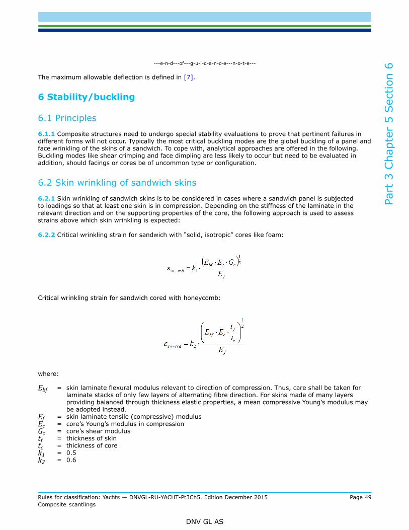
Part
3 C
hapt
er 5
Sec
tion
6
Rules for classification: Yachts — DNVGL-RU-YACHT-Pt3Ch5. Edition December 2015 Page 49Composite scantlings
DNV GL AS
---e-n-d---of---g-u-i-d-a-n-c-e---n-o-t-e---
The maximum allowable deflection is defined in [7].
6 Stability/buckling
6.1 Principles
6.1.1 Composite structures need to undergo special stability evaluations to prove that pertinent failures indifferent forms will not occur. Typically the most critical buckling modes are the global buckling of a panel andface wrinkling of the skins of a sandwich. To cope with, analytical approaches are offered in the following.Buckling modes like shear crimping and face dimpling are less likely to occur but need to be evaluated inaddition, should facings or cores be of uncommon type or configuration.
6.2 Skin wrinkling of sandwich skins
6.2.1 Skin wrinkling of sandwich skins is to be considered in cases where a sandwich panel is subjectedto loadings so that at least one skin is in compression. Depending on the stiffness of the laminate in therelevant direction and on the supporting properties of the core, the following approach is used to assessstrains above which skin wrinkling is expected:
6.2.2 Critical wrinkling strain for sandwich with “solid, isotropic” cores like foam:
Critical wrinkling strain for sandwich cored with honeycomb:
where:
Ebf = skin laminate flexural modulus relevant to direction of compression. Thus, care shall be taken forlaminate stacks of only few layers of alternating fibre direction. For skins made of many layersproviding balanced through thickness elastic properties, a mean compressive Young’s modulus maybe adopted instead.
Ef = skin laminate tensile (compressive) modulusEc = core’s Young’s modulus in compressionGc = core’s shear modulustf = thickness of skintc = thickness of corek1 = 0.5k2 = 0.6

Part
3 C
hapt
er 5
Sec
tion
6
Rules for classification: Yachts — DNVGL-RU-YACHT-Pt3Ch5. Edition December 2015 Page 50Composite scantlings
DNV GL AS
6.3 Buckling of orthotropic plates under membrane loads6.3.1 Considerations and limitations:The buckling of sandwich panels needs to be considered for global in-plane compression and in-plane shear.The following methodology is based on simplified classical laminate theory, i.e. only valid for laminate plates(sandwich or single skin) which are well balanced through thickness. Only sandwich laminates with skin in-plane, tensile stiffness (E ∙ t) difference of no more than 20 % in each direction x or y may be considered thisway:
and:
where “os” and “is” are indices for “outer skin” and “inner skin”. Also, all edges need to be supported. Thereis no implementation for the possibility to calculate plates with one free edge. This condition presumes thatthere will be no or only minor coupling between in-plane and out-of-plane effects.
6.3.2 Critical buckling strains for panel under uni-axial in-plane compression:For arbitrary boundary conditions the critical membrane strain of an orthotropic plate that leads to bucklingis:
where:
Ea-mean = mean Young’s modulus in load direction (a) of full laminate (incl. core)ttot = total thickness of full laminate (incl. core)b = plate width perpendicular to load directiona = plate width parallel to load directionkx = buckling coefficient
=q = boundary condition adjustment factor
= 2for unloaded edges simply supported= 2.36for unloaded edges clamped= see Figure 14 Simplified curves= modified aspect ratio
=
β = “Seydel” orthotropic parameter
=
Coefficients from the laminate’s bending matrix D:
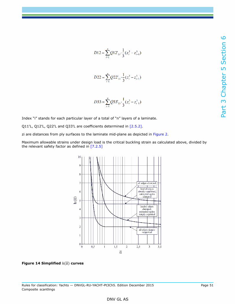
Part
3 C
hapt
er 5
Sec
tion
6
Rules for classification: Yachts — DNVGL-RU-YACHT-Pt3Ch5. Edition December 2015 Page 51Composite scantlings
DNV GL AS
Index “i” stands for each particular layer of a total of “n” layers of a laminate.
Q11'L, Q12'L, Q22'L and Q33'L are coefficients determined in [2.5.2].
zi are distances from ply surfaces to the laminate mid-plane as depicted in Figure 2.
Maximum allowable strains under design load is the critical buckling strain as calculated above, divided bythe relevant safety factor as defined in [7.2.5]
Figure 14 Simplified curves
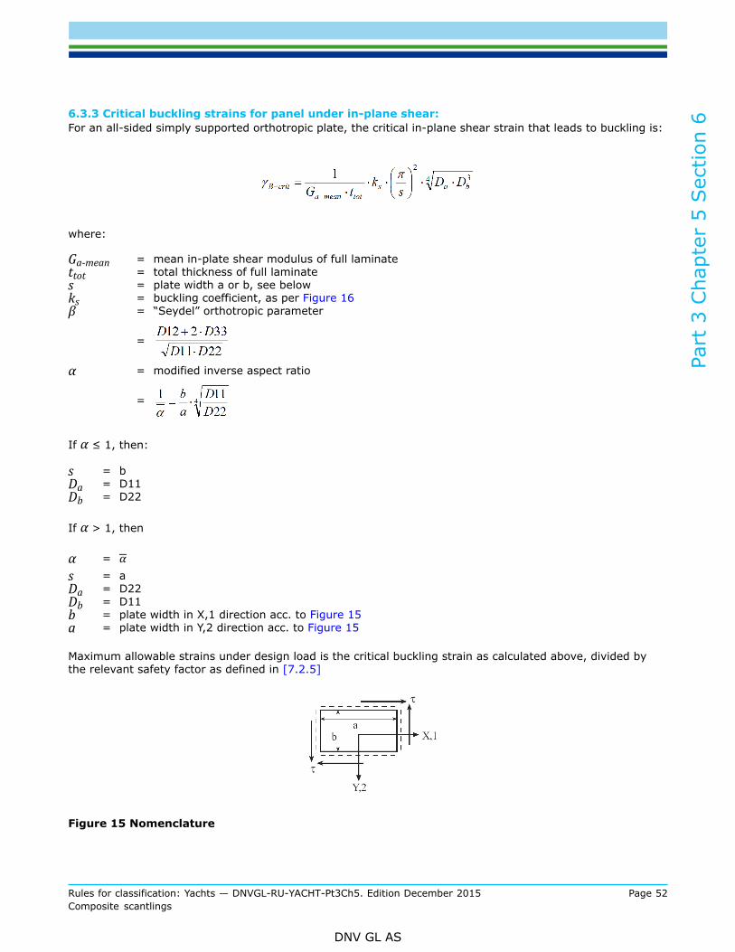
Part
3 C
hapt
er 5
Sec
tion
6
Rules for classification: Yachts — DNVGL-RU-YACHT-Pt3Ch5. Edition December 2015 Page 52Composite scantlings
DNV GL AS
6.3.3 Critical buckling strains for panel under in-plane shear:For an all-sided simply supported orthotropic plate, the critical in-plane shear strain that leads to buckling is:
where:
Ga-mean = mean in-plate shear modulus of full laminatettot = total thickness of full laminates = plate width a or b, see belowks = buckling coefficient, as per Figure 16β = “Seydel” orthotropic parameter
=
α = modified inverse aspect ratio
=
If α ≤ 1, then:
s = bDa = D11Db = D22
If α > 1, then
α =s = aDa = D22Db = D11b = plate width in X,1 direction acc. to Figure 15a = plate width in Y,2 direction acc. to Figure 15
Maximum allowable strains under design load is the critical buckling strain as calculated above, divided bythe relevant safety factor as defined in [7.2.5]
Figure 15 Nomenclature

Part
3 C
hapt
er 5
Sec
tion
6
Rules for classification: Yachts — DNVGL-RU-YACHT-Pt3Ch5. Edition December 2015 Page 53Composite scantlings
DNV GL AS
Figure 16 Buckling coefficient ks
6.4 Buckling of beams, girders, stringers
6.4.1 Beams, girders, stringers etc. shall be analysed with respect to global buckling due to axialcompression. The flanges and webs shall be analysed with respect to local buckling due to axial load, bendingmoment and shear load.
6.4.2 For closed section beams with adequate stiffness or support with respect to tripping, the critical axialglobal buckling load is given by:
where:
D = bending stiffness of the beam with associated plating, EI (Nmm2)l = the free span of the beam (mm)DQ = tw hw Gw (Nmm2)tw = combined thickness of stiffener web(s) (sum of all web thicknesses) (mm)hw = height of the beam web (mm)Gw = shear modulus of the beam web (MPa)
Maximum allowable compressive design load is the critical compressive force as calculated above, divided bythe relevant safety factor as defined in [7.2.5]
6.4.3 The critical axial stress in the top flange of top-hat cross sections not supported by a structural corecan be calculated as for single skin panels.The fitting of tripping brackets may be required by the Society.
Part
3 C
hapt
er 5
Sec
tion
6
Rules for classification: Yachts — DNVGL-RU-YACHT-Pt3Ch5. Edition December 2015 Page 54Composite scantlings
DNV GL AS
6.4.4 The critical shear strain with respect to shear buckling in the webs of stiffeners may be calculatedaccording to [6.3]Maximum allowable strains under design load is the critical buckling strain as calculated above, divided bythe relevant safety factor as defined in [7.2.5]
6.5 Buckling of stiffened plate field
6.5.1 Stiffened plate fields can be analysed using formulas developed for such structures fabricated fromsteel according Ch.4 provided conservative assumptions are made regarding the stiffness of cross sections ofstiffeners and plating are made.
6.6 Buckling of composite columns
6.6.1 All supporting columns made of composites are to be checked on their buckling capacity by usingsimple Euler Theory of linear buckling, applying a safety factor as given in [7.2.5].
6.7 Buckling of steel and aluminium pillars
6.7.1 The cross sectional area of members subjected to compressive loads is not to be less than:
where:
h = minimum 0.3
P = axial load in kN as given for various strength members in [2.2.2] and [2.2.3].Alternatively, P may be obtained from direct stress analysis
l = length of member in mi = radius of gyration in cmk = 0.7 in general
= 0.6 when design loads are primarily dynamic
sc =
=
sE =
sF = minimum upper yield stress of materialE = modulus of elasticity for steel = 210 000 MPa, for aluminium = 70 000 MPa.
The formula given for sE is based on hinged ends and axial forces only.

Part
3 C
hapt
er 5
Sec
tion
6
Rules for classification: Yachts — DNVGL-RU-YACHT-Pt3Ch5. Edition December 2015 Page 55Composite scantlings
DNV GL AS
If, in special cases, it is verified that one end can be regarded as fixed, then the value of sE may bemultiplied by 2.
If it is verified that both ends can be regarded as fixed, the value of sE may be multiplied by 4.
In case of eccentric force, additional end moments or additional lateral pressure, the strength member is tobe reinforced to withstand bending stresses.
6.8 Pillars in tanks
6.8.1 Hollow pillars are not accepted within fuel tanks.
6.8.2 Where the hydrostatic pressure may give tensile stresses in the pillars and cross members, theirsectional area is not to be less than:
A = 0.07 Adk · pt (cm2)
(The formula may be used also for tension control of panting beams and cross ties in tanks.)
where:
Adk = deck or side area in m2 supported by the pillar or cross memberpt = design pressure, p in kN/m2 giving tensile stress in the pillar
Doubling plates at ends are not allowed.
7 Design rules
7.1 Assessment concept
7.1.1 Within this section, the assessment of structural reliability is performed using the “Failure RatioConcept”. This concept implies the criteria as per [7.1.1] and [7.1.2].The Failure Ratio Concept may solely be used in association with the provisions described and defined so far,thus will not automatically be applicable for different methodologies or different load definitions.
7.1.2 Maximum strain criteria:The “Maximum Strain Criteria” is applicable for all aspects of assessing strength and stability of laminates. Itis providing an appropriate measure for fibre reinforced composites under the condition that the compositeshows a fibre-dominant load transfer. The defined limits provide a sufficient margin over interlaminar microcracking and fibre failure in all in-plane directions and are considered providing sufficient structural reliability.
7.1.3 Maximum stress criteria:The “Maximum Stress Criteria” is applicable for all aspects not covered by [7.1.1], such as sandwich corestrength, laminate strength when calculated in accordance with Sec.4 [2.5], bonding strength, interlaminarshear and other matrix-dominant failure modes.
7.2 Allowable strains/stresses
7.2.1 The failure ratio concept includes the definition of maximum allowable stresses and strains. Ratios arebeing defined for sufficient strength and stability.
Part
3 C
hapt
er 5
Sec
tion
6
Rules for classification: Yachts — DNVGL-RU-YACHT-Pt3Ch5. Edition December 2015 Page 56Composite scantlings
DNV GL AS
7.2.2 Stresses/strains derived in accordance with the provisions in these rules shall not exceed the valuesgiven by the following equation:
where:
Fr = Reference mechanical strength/resistance as per [6], [7.2.3] and [7.2.4]R = Reserve factor [7.2.5]Cc = Equal to 0.8 for watertight bulkhead structures under hydrostatic load in
= damaged condition.Equal to 1.0 otherwise and for other structures.
Crm = Equal to 0.90 for vacuum assisted production (VARTM, pre-preg).= Equal to 1.0 otherwise.
7.2.3 Laminates- Reference mechanical strength/resistanceThe allowable stresses and/or strains for laminates are related to on their reference mechanical strength.
Two different approaches are acceptable:
— Reference mechanical strength/resistance is represented by the ultimate strength, determined by testing— Reference mechanical strength/resistance is represented by generic assumptions of the ultimate strength,
without test data
When tested values are used, testing and the specification of reference mechanical strength Fr shall becarried out in accordance with the requirements in Sec.2 [3.1].
When generic assumptions are used, Table 3 applies. This table can be used as an alternative to the use oftesting.
Mixing of generic assumption values and values determined by testing is subject to approval by the Society.
Table 4 Reference mechanical strength/resistance values based on strength values derived fromtests in accordance with definitions in Sec.2
Laminates Frt Ultimate strength/strain values, tested (ref. Sec.2 [3.2])
Matrix dominantlaminate behaviour Frm Interlaminar shear strength values, tested
Static shear strength proved by approval certificate or qualification testing (msmv)for quasi-static applicationsSandwich core Frc
Dynamic shear strength proved by approval certificate for slamming applications
Table 5 Reference values ('generic') in absence of tested values as defined in Sec.2
Default ultimate strain* default values:
0.65% HS Carbon, uniaxial strain
** HM Carbon, uniaxial strain
1.2% E-Glass, uniaxial strain
Laminates, generic Frg
0.40% Aramid, uniaxial strain
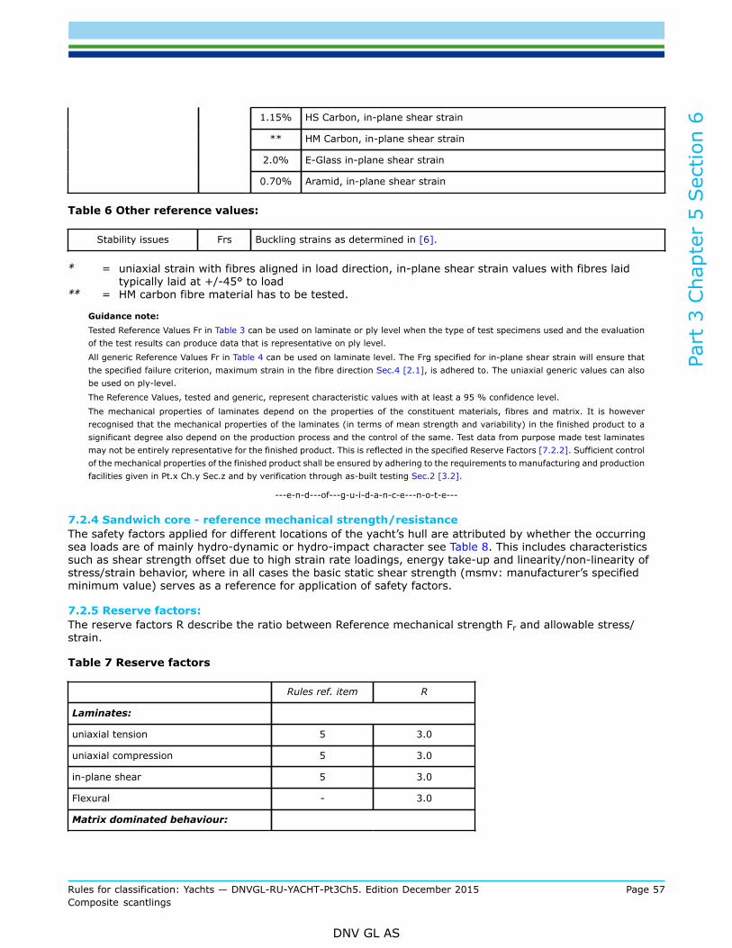
Part
3 C
hapt
er 5
Sec
tion
6
Rules for classification: Yachts — DNVGL-RU-YACHT-Pt3Ch5. Edition December 2015 Page 57Composite scantlings
DNV GL AS
1.15% HS Carbon, in-plane shear strain
** HM Carbon, in-plane shear strain
2.0% E-Glass in-plane shear strain
0.70% Aramid, in-plane shear strain
Table 6 Other reference values:
Stability issues Frs Buckling strains as determined in [6].
* = uniaxial strain with fibres aligned in load direction, in-plane shear strain values with fibres laidtypically laid at +/-45° to load
** = HM carbon fibre material has to be tested.
Guidance note:Tested Reference Values Fr in Table 3 can be used on laminate or ply level when the type of test specimens used and the evaluationof the test results can produce data that is representative on ply level.All generic Reference Values Fr in Table 4 can be used on laminate level. The Frg specified for in-plane shear strain will ensure thatthe specified failure criterion, maximum strain in the fibre direction Sec.4 [2.1], is adhered to. The uniaxial generic values can alsobe used on ply-level.The Reference Values, tested and generic, represent characteristic values with at least a 95 % confidence level.The mechanical properties of laminates depend on the properties of the constituent materials, fibres and matrix. It is howeverrecognised that the mechanical properties of the laminates (in terms of mean strength and variability) in the finished product to asignificant degree also depend on the production process and the control of the same. Test data from purpose made test laminatesmay not be entirely representative for the finished product. This is reflected in the specified Reserve Factors [7.2.2]. Sufficient controlof the mechanical properties of the finished product shall be ensured by adhering to the requirements to manufacturing and productionfacilities given in Pt.x Ch.y Sec.z and by verification through as-built testing Sec.2 [3.2].
---e-n-d---of---g-u-i-d-a-n-c-e---n-o-t-e---
7.2.4 Sandwich core - reference mechanical strength/resistanceThe safety factors applied for different locations of the yacht’s hull are attributed by whether the occurringsea loads are of mainly hydro-dynamic or hydro-impact character see Table 8. This includes characteristicssuch as shear strength offset due to high strain rate loadings, energy take-up and linearity/non-linearity ofstress/strain behavior, where in all cases the basic static shear strength (msmv: manufacturer’s specifiedminimum value) serves as a reference for application of safety factors.
7.2.5 Reserve factors:The reserve factors R describe the ratio between Reference mechanical strength Fr and allowable stress/strain.
Table 7 Reserve factors
Rules ref. item R
Laminates:
uniaxial tension 5 3.0
uniaxial compression 5 3.0
in-plane shear 5 3.0
Flexural - 3.0
Matrix dominated behaviour:
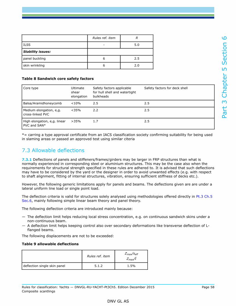
Part
3 C
hapt
er 5
Sec
tion
6
Rules for classification: Yachts — DNVGL-RU-YACHT-Pt3Ch5. Edition December 2015 Page 58Composite scantlings
DNV GL AS
Rules ref. item R
ILSS - 5.0
Stability issues:
panel buckling 6 2.5
skin wrinkling 6 2.0
Table 8 Sandwich core safety factors
Core type Ultimateshearelongation
Safety factors applicablefor hull shell and watertightbulkheads
Safety factors for deck shell
Balsa/Aramidhoneycomb <10% 2.5 2.5
Medium elongation, e,g.cross-linked PVC
<35% 2.2 2.5
High elongation, e,g. linearPVC and SAN*
>35% 1.7 2.5
*= carring a type approval certificate from an IACS classification society confirming suitability for being usedin slaming areas or passed an approved test using similar citeria
7.3 Allowable deflections
7.3.1 Deflections of panels and stiffeners/frames/girders may be larger in FRP structures than what isnormally experienced in corresponding steel or aluminium structures. This may be the case also when therequirements for structural strength specified in these rules are adhered to. It is advised that such deflectionsmay have to be considered by the yard or the designer in order to avoid unwanted effects (e.g. with respectto shaft alignment, fitting of internal structures, vibration, ensuring sufficient stiffness of decks etc.).
However, the following generic limitations apply for panels and beams. The deflections given are are under alateral uniform line load or single point load.
The deflection criteria is valid for structures solely analysed using methodologies offered directly in Pt.3 Ch.5Sec.6, mainly following simple linear beam theory and panel theory.
The following deflection criteria are introduced mainly because:
— The deflection limit helps reducing local stress concentration, e.g. on continuous sandwich skins under anon-continuous beam.
— A deflection limit helps keeping control also over secondary deformations like transverse deflection of L-flanged beams.
The following displacements are not to be exceeded:
Table 9 allowable deflections
Rules ref. itemZmax/seff
Zmax/l
deflection single skin panel 5.1.2 1.5%

Part
3 C
hapt
er 5
Sec
tion
6
Rules for classification: Yachts — DNVGL-RU-YACHT-Pt3Ch5. Edition December 2015 Page 59Composite scantlings
DNV GL AS
Rules ref. itemZmax/seff
Zmax/l
deflection sandwich panel 5.1.2 1.0%
deflection stiffener / girder 5.2.3 0.5%
deflection engine foundation 5.2.3 0.3%
Zmax = maximum deflection from [5.1.2] and [5.2.3]Seff = effective panel span from [3.2.4]l = beam span from [4.2.2]
Guidance note:(repeated from [5.1.2] and [5.2.3]:The deflections calculated according to [5.1.2] and [5.2.3] may underestimate real deflections as they do not include the effect ofthe so-called shear deflection.
---e-n-d---of---g-u-i-d-a-n-c-e---n-o-t-e---
Part
3 C
hapt
er 5
Sec
tion
7
Rules for classification: Yachts — DNVGL-RU-YACHT-Pt3Ch5. Edition December 2015 Page 60Composite scantlings
DNV GL AS
SECTION 7 LOCAL STRUCTURAL DESIGN
1 Design details— The occurrence of peeling effects such as abrupt stiffness changes is to be minimised. Secondary bonding
is always to be backfilled with suitably coved filler bed.— Core chamfers of sandwich panels should not be steeper than 1/3.— Exposed fibres and sandwich cores shall be sealed or clashed.— Through-sandwich penetrations shall be adequately designed, e.g. by installing appropriate skin ties and/
or back-fill with structural filler.
2 Minimum laminate reinforcement weight
2.1 Minimum shell thicknessApart from the provisions explicitly defined in this Section, no particular algorithm has been implementedto define a minimum shell or skin thickness for hull laminates, covering wear and tear and local forces orimpact, e.g. when docking, dry docking or from collision with floating or submerged debris.
Guidance note:Recommendations about minimum skin thickness can be obtained from HSLC Pt.3 Ch.4 Sec.7 [2.2]
---e-n-d---of---g-u-i-d-a-n-c-e---n-o-t-e---
3 Bow impact protectionVessels built in sandwich construction shall have the fore stem designed so that a local impact at or belowthe water line will not result in skin laminate peeling due to hydraulic pressure. This shall be achieved byconnecting the two skin laminates.The distance a Figure 1 from the stem to the location of the connection of the two skins shall not be lessthan:
With v and D defined in Ch.1.The vertical extension of the collision protection shall be from the keel to a point 0.03 L (m) above the waterline at operating speed.Within the vertical extension of the collision protection the stem laminate shall be increased to a thicknessnot less than:
where σnu is the ultimate tensile strength of the laminate (MPa).

Part
3 C
hapt
er 5
Sec
tion
7
Rules for classification: Yachts — DNVGL-RU-YACHT-Pt3Ch5. Edition December 2015 Page 61Composite scantlings
DNV GL AS
Figure 1 Collision Protection
The connection of the skin laminates can be arranged as shown in Figure 2. Other alternatives providing thesame degree of protection can be accepted.
Figure 2 Laminate connection
4 Bolting
4.1 Introduction
4.1.1 In this paragraph the general requirements for strength of the following bolted connections are given:
— bolted connections for transfer of in-plane loads (shear connections)— bolted connections for transfer of out-of-plane loads— bolt inserts and similar attachments (not participating in the structural strength of the hull and
superstructure).
The definition of in-plane and out-of-plane loads refers to the load components on each individual bolt.Guidance note:A bollard may be subjected to a load parallel to the laminate plane. However, due to the bending moment on the bollard (the pointof attack of the load is some distance above the panel) the individual bolts securing the bollard to the panel may be subjected toan out-of-plane load, additional to the in-plane load. Such bolted connections shall be designed with respect to both in-plane andout-of-plane loads.
---e-n-d---of---g-u-i-d-a-n-c-e---n-o-t-e---
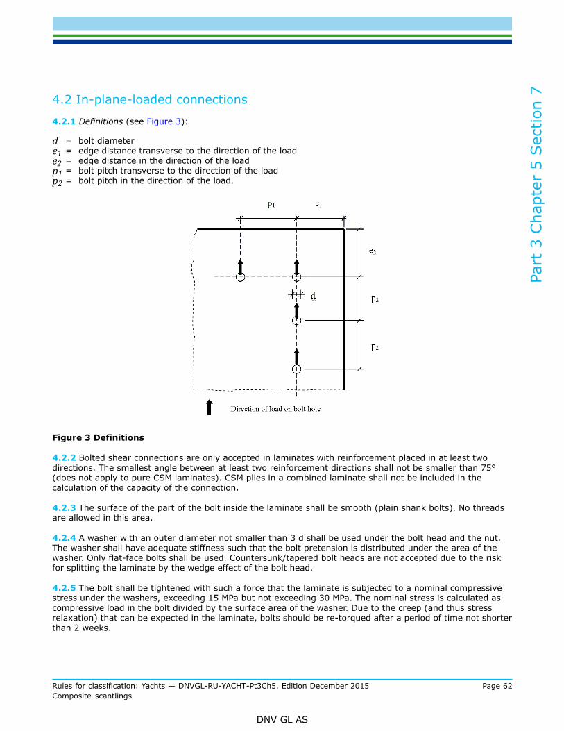
Part
3 C
hapt
er 5
Sec
tion
7
Rules for classification: Yachts — DNVGL-RU-YACHT-Pt3Ch5. Edition December 2015 Page 62Composite scantlings
DNV GL AS
4.2 In-plane-loaded connections
4.2.1 Definitions (see Figure 3):
d = bolt diametere1 = edge distance transverse to the direction of the loade2 = edge distance in the direction of the loadp1 = bolt pitch transverse to the direction of the loadp2 = bolt pitch in the direction of the load.
Figure 3 Definitions
4.2.2 Bolted shear connections are only accepted in laminates with reinforcement placed in at least twodirections. The smallest angle between at least two reinforcement directions shall not be smaller than 75°(does not apply to pure CSM laminates). CSM plies in a combined laminate shall not be included in thecalculation of the capacity of the connection.
4.2.3 The surface of the part of the bolt inside the laminate shall be smooth (plain shank bolts). No threadsare allowed in this area.
4.2.4 A washer with an outer diameter not smaller than 3 d shall be used under the bolt head and the nut.The washer shall have adequate stiffness such that the bolt pretension is distributed under the area of thewasher. Only flat-face bolts shall be used. Countersunk/tapered bolt heads are not accepted due to the riskfor splitting the laminate by the wedge effect of the bolt head.
4.2.5 The bolt shall be tightened with such a force that the laminate is subjected to a nominal compressivestress under the washers, exceeding 15 MPa but not exceeding 30 MPa. The nominal stress is calculated ascompressive load in the bolt divided by the surface area of the washer. Due to the creep (and thus stressrelaxation) that can be expected in the laminate, bolts should be re-torqued after a period of time not shorterthan 2 weeks.

Part
3 C
hapt
er 5
Sec
tion
7
Rules for classification: Yachts — DNVGL-RU-YACHT-Pt3Ch5. Edition December 2015 Page 63Composite scantlings
DNV GL AS
4.2.6 The pitch transverse to the direction of the load shall satisfy p1 ≥ 5 d.The pitch in the direction of the load shall satisfy p2 ≥ 4 d.The edge distance transverse to the direction of the load shall satisfy e1 ≥ 3 d.The edge distance in the direction of the load shall satisfy the following requirement:e2 ≥ 4 d.
4.2.7 The nominal bearing stress shall satisfy the following requirement:
where:
σ bear = shear load divided by d · tt = thickness of structural laminateγ = 1.0 for holes with a difference between bolt and hole diameter less than 0.1 mmγ = 1.6 for holes with a difference between bolt and hole diameter of less than 1.0 mm
The default values of the bearing stress capacity given in Table 1 can be used.
Table 1 Default values of the bearing stress capacity
Type of reinforcementNominal bearing stress strength,
Rbear (MPa)
Glass, woven rowing 200 (Vf/0.33)
Glass, multiaxial laminates 250 (Vf/0.33)
Glass, CSM 75 (Vf/0.33)
Carbon, woven rowing 275 (Vf/0.50)
Carbon, multiaxial laminates 325 (Vf/0.50)
Aramid, woven rowing Considered specially
Aramid, multiaxial laminates Considered specially
Vf = volume fraction of reinforcement in laminates excluding CSM
Higher bearing stress capacity can be used based on representative test results.
For hybrid laminates Rbear can be found by liner interpolation based on the volume fraction of the respectivetypes of fibre.
Guidance note:The requirements are such that it is highly probable that the failure mode will be that the bearing stress will exceed the capacityaround the edge of the hole.
---e-n-d---of---g-u-i-d-a-n-c-e---n-o-t-e---
Part
3 C
hapt
er 5
Sec
tion
7
Rules for classification: Yachts — DNVGL-RU-YACHT-Pt3Ch5. Edition December 2015 Page 64Composite scantlings
DNV GL AS
4.3 Out-of-plane loaded connections
4.3.1 A connection for out-of–plane loads shall be bolted through the panel, in sandwich panels throughboth skins. For attachments not participating in the structural strength of the hull and superstructure otherarrangements may be accepted by the Society.
4.3.2 Washers or plates shall be provided on both sides of the panel to distribute the load from bolt headsand nuts. These washers or plates may be fabricated from metallic materials or from fibre reinforcedthermosets.Their bending stiffness shall be large enough to ensure a distribution of the load from each bolt over asufficiently large area to prevent compressive overloading of the panel in-between the washers or plates. Thecompressive stress under the washer or plates shall not anywhere exceed 30% of the compressive strengthof the skin and core, respectively.
4.3.3 The global effect of the out-of-plane load on the panel (in-plane bending moments and throughthickness shear) shall be calculated according to recognised methods for the calculation of load effects inpanels subjected to concentrated loads. The stress levels in laminates, skins and core shall not exceed thestress level accepted for hull panels in bottom exposed to slamming.
4.3.4 Other arrangements may be accepted based on test results. Such testing shall be carried out onconnections with representative design on representative panels subjected to representative loads includingall in-plane and out-of-plane components. The allowable loads on the connection shall not exceed the loweststrength recorded from at least three such test divided by the factor of 3.
4.4 Inserts and Attachments
4.4.1 Inserts and attachments may be used for transferring in-plane and out-of-plane loads for connectionsnot participating in the structural strength of the hull and superstructure.
4.4.2 Where adequate, the methods for design described above may be used. Where these methods are notadequate the allowable load shall be determined by testing. Such testing shall be carried out on inserts orattachments with representative design on representative panels subjected to representative loads includingall in-plane and out-of-plane components. The allowable loads on the insert/attachment shall not exceed thelowest strength recorded from at least three such test divided by the factor of 3.
5 Bonded joints
5.1 Application
5.1.1 This section applies to a bonded joint defined as follows: a joint where adherents are bonded eitherby placing a layer of adhesive or resin material between the adherents or by producing a bond between oneadherent and the second adherent as an integral part of the manufacturing of the joint or the structure,e.g. by applying laminates or laminating directly onto a metal surface, or any combination of the above.Secondary bonds in FRP constructions are not covered by this section.
5.1.2 The use of bonded joints is subject to the approval of the Society. Bonded joints are normally notaccepted for transfer of the global loads on the hull or on joints, the failure of which would compromise thewatertight integrity of the vessel. Deviations from this may be accepted by the Society based on specialconsideration.
5.1.3 Adhesives used for bonded joints shall be type approved as rigid adhesives by the Society.

Part
3 C
hapt
er 5
Sec
tion
7
Rules for classification: Yachts — DNVGL-RU-YACHT-Pt3Ch5. Edition December 2015 Page 65Composite scantlings
DNV GL AS
5.2 Design of bonded joints
5.2.1 The function(s) of the joint shall be to transfer load by shear along the bondline. Peel loads shall beavoided.
5.2.2 The nominal shear stress over the bond surface shall not by itself be used as a characteristic of theload level in the joint. The design shall be based on line load, global load or an analysis of the shear stresstaking due account of the stress concentrations in the joint.
5.2.3 The physical environment of the joint shall be specified and considered in the design. As a minimumthe following factors shall be considered:
— humidity— UV-light— temperature— chemicals (e.g. fuel etc.)— welding— fire
Welding on adjacent structures and fire may increase the temperature at the bond. This effect shall beconsidered when specifying short and long term service temperature for the joint.
5.2.4 The design of bonded joints shall be based on qualification tests carried out on realistic samples, see[3.1]. The properties obtained in a yard may differ significantly from the properties measured on specimenstested under laboratory conditions. Causes for such differences may be different working environment,scaling effects etc. This difference shall be reflected in the design strength of the joint: the strength of thejoint cannot be assumed to be as high as determined in the qualification tests.
5.2.5 For static strength verifications, a nominal allowable shear stress of
t = 7 N/mm2
can be used without further verification, in the case of multi-component thermosetting adhesive approved bythe Society. A stress concentration arising in the structural joint is covered up to a factor of 3. This value maybe assumed for bonded joints of shell with negligible level peeling forces.
5.2.6 The adherents, surface preparation and fabrication procedures shall be identical to the joint as for thesamples on which the qualification tests have been carried out.
5.2.7 The joint cross section and the direction of the load transfer shall for all parameters influencingthe strength and durability of the joint be identical to the joint geometry tested in the qualification tests.Alternatively, a change in any of these parameters may be accepted if they do not lead to a reduction of thestrength or durability of the joint.Special attention shall be given to the length of the overlap, the stiffness of the adherents and the out-ofplane forces in the joint. The length of the overlap shall not be smaller than on the tested joint. The thicknessof the adherents shall not be smaller than used in the qualification tests.

DNV GLDriven by our purpose of safeguarding life, property and the environment, DNV GL enablesorganizations to advance the safety and sustainability of their business. We provide classification andtechnical assurance along with software and independent expert advisory services to the maritime,oil and gas, and energy industries. We also provide certification services to customers across a widerange of industries. Operating in more than 100 countries, our 16 000 professionals are dedicated tohelping our customers make the world safer, smarter and greener.
SAFER, SMARTER, GREENER