rule-based detection of inconsistency in … · rule-based detection of inconsistency in software...
TRANSCRIPT

RUL E-BASED DETECTI ON OF
I NCONSI STENCY I N SOFTWARE DESI GN
by
WenQian Liu
A thesis submi tted in conformi ty wi th the requi rements for the degree of Master of Science
Graduate Department of Computer Science Universi ty of Toronto
Copyright © 2002 by WenQian Liu

ii
Abstr act
RULE-BASED DETECTION OF INCONSI STENCY I N SOFTWARE DESIGN
WenQian L iu
Master of Science
Graduate Department of Computer Science
University of Toronto
2002
Software design inconsistency can be hard to trace manually. Computer assistance in
detecting and resolving inconsistency issues can help improve the quality of sophisticated
software designs. Existing solutions include design guidance, critiquing system and static
consistency checking. Related research includes inconsistency management of requirements
such as goal conflict resolution, viewpoints, and overlaps. However, none of these
approaches integrate their solutions into the design process effectively.
This thesis describes a rule-based (or production system) solution to the
aforementioned problem. We characterize classes of inconsistency that occur in software
design. We define a production system language and rules specific to software designs
modeled in UML. We demonstrate our solution on a design exemplar. Using this approach,
we are able to detect inconsistencies, notify the users, recommend resolutions, and
automatically fix the inconsistency during the design process. However, the expressiveness
of production language is limited due to the informality of UML.

iii
Table of Contents
Chapter 1 Introduction 1
Chapter 2 Related Work 4
2.1 Design Inconsistency Research ....................................................................4
2.2 Other Related Work .....................................................................................7
Chapter 3 A Classification Scheme for Design Inconsistency 11
3.1 Redundancy ...............................................................................................12
3.1.1 Redundancy in Design Representation............................................................12
Structural Redundancy.........................................................................................13
Feature Dependence - Specialization....................................................................14
Feature Interference.............................................................................................16
3.1.2 Redundancy in Data Representation ...............................................................18
3.2 Conformance to Constraints and Standards ................................................19
3.2.1 Intra-system Conflicts ....................................................................................20
3.2.2 Inter-system Mismatches................................................................................20
3.2.3 Constraints of Modeling Languages ...............................................................21
3.2.4 Design Standards............................................................................................21
3.2.5 Design Patterns ..............................................................................................24
3.3 Change.......................................................................................................26
3.3.1 Edit Blocks.....................................................................................................26

iv
3.3.2 Design Model Transformation........................................................................26
Chapter 4 Inconsistency Identification 28
4.1 Production Systems ...................................................................................28
4.1.1 Working Memory...........................................................................................29
4.1.2 Production Rules............................................................................................30
4.1.3 Conflict Resolution ........................................................................................30
4.1.4 Applications and Advantages .........................................................................31
4.2 Inconsistency Identification Using Production System...............................32
4.2.1 The General Mechanism of the Method..........................................................32
4.2.2 Definitions for Working Memory Elements....................................................33
Class Diagram, Class...........................................................................................34
Association..........................................................................................................34
State Diagram......................................................................................................35
Sequence Diagram...............................................................................................35
Inconsistency Resolution Elements ......................................................................35
4.2.3 Inconsistency Rules........................................................................................36
Naming Inconsistency between Behavioral and Structural Diagrams....................36
Feature Dependence – Specialization ...................................................................38
Feature Interference.............................................................................................40
UML Constraints.................................................................................................40
Standards Conformance Rules..............................................................................41
Pattern Recognition Rules....................................................................................42
4.2.4 Resolution Rules............................................................................................43
4.2.5 Cleanup Rules................................................................................................45

v
4.2.6 Orphan Control Rules.....................................................................................46
4.2.7 Dynamic Controls ..........................................................................................47
Chapter 5 Implementation 49
5.1 Architecture ...............................................................................................49
5.2 Example.....................................................................................................51
5.3 Analysis.....................................................................................................54
5.4 Implementation Issues................................................................................56
Chapter 6 Conclusions and Future Work 59
References 61
Appendix A More Inconsistency Classes 67
A.1 Data Related Consistency...........................................................................68
A.1.1 Data Recoverability........................................................................................68
A.1.2 Data Caching..................................................................................................68
A.2 Control .......................................................................................................70
A.2.1 Concurrency, Parallelism and Sharing ............................................................70
A.3 Human Factor.............................................................................................70
A.3.1 Expressiveness...............................................................................................70
Appendix B Jess Scr ipts 72
B.1 Data File.....................................................................................................72
B.2 Jess Script of the Rule UML-C2.................................................................72

vi
Table of Figures
Figure 3–1 Duplicate Attribute Causes a Structural Redundancy....................................14
Figure 3–2 Use Case Diagram: Request a New Meeting ................................................15
Figure 3–3 Sequence Diagram: Request a New Meeting ................................................15
Figure 3–4 Sequence Diagram: Request a Specific Meeting...........................................16
Figure 3–5 Feature Interference – Variant I....................................................................17
Figure 3–6 Feature Interference – Variant II ..................................................................17
Figure 3–7 Telephone Feature Interference....................................................................17
Figure 3–8 Data Representation Redundancy in the Meeting Scheduler Example...........19
Figure 3–9 Violation of the Law of Demeter – Library example.....................................23
Figure 3–10 Correction to the Violation of the Law of Demeter – Library Example.........23
Figure 3–11 The Singleton design pattern. .......................................................................25
Figure 3–12 The Façade design pattern (on the right).......................................................25
Figure 5–1 The Architecture of the RIDE System..........................................................50
Figure 5–2 The Network For Production Rule UML-2. ..................................................52

vii
L ist of Tables
Table 3-1 Summary of Inconsistency Types.................................................................27

1
Chapter 1
I ntr oduction
Software systems have become indispensable in our daily activities. From grocery stores to
online commerce, from building architecture to car manufacturing, from communications to
entertainment, from local administration to national defense, software systems are critical to
the functioning of our society. With the increasing demand for a software system in nearly
every aspect of our life, the functional requirements of the system are growing, the time to
market is shortening, the interface must be user-friendly, and the system must fit the
operating environment seamlessly.
To master the complexity of software development projects, software engineers employ well
defined development processes such as the Waterfall Model [Royce, 1970], and the Spiral
Model [Boehm, 1988], and tackle the problem in four main phases typically identified as the
following: requirements elicitation and analysis, architectural and detailed design,
implementation, and testing. However, the development tasks involved in each phase are
still too complex to be completed by individuals. In addition, due to geographical constraints,
development teams can be working from sites distributed all over the world. This introduces
the problem of maintaining consistency throughout the development phases in a distributed
environment. A design is inconsistent if the design conveys conflicting information about

CHAPTER 1. INTRODUCTION 2
the system, and/or violates predefined constraints. Such constraints include both good
practices for this kind of designs and specific requirements from the stakeholders for this
system. An inconsistency is an instance of such occurrence. To manually identify and
resolve design inconsistencies can be tedious and error prone. Computer assistance in
handling design consistency issues is inevitably required.
Currently, a few research teams have made some progress in providing computer-based
design consistency handling, notably the xlinkit tool [Nentwich et al., 2002], Argo/UML
[Robbins et al., 1997], and the process-oriented design guidance approach
[Cass and Osterweil, 2000]. However, a classification of design inconsistencies is yet to be
defined. Attempts have been made in classifying requirements inconsistency
[Lamsweerde et al., 1998] to date.
We are interested in developing a software design environment that automates the detection
and resolution of design inconsistencies in design models. In achieving this, we first define a
classification scheme of design inconsistencies that occur in the design representation, and
describe our approach based on these classes of inconsistencies. In this thesis, we define a
classification scheme of design inconsistencies; describe an inconsistency identification
mechanism specific to Unified Modeling Language (UML) [Rumbaugh et al., 1999] design
models; and illustrate the application on a software design exemplar.
Chapter 2 introduces a number of related works. Chapter 3 describes a classification scheme
of design inconsistencies. Chapter 4 introduces production systems; defines selected UML
constructs in production terms; and formalizes design inconsistency rules. Chapter 5
describes the architecture of the implementation; illustrates the method on a software design

CHAPTER 1. INTRODUCTION 3
exemplar; analyzes the approach; and discusses key implementation issues. Chapter 6 draws
conclusions and summarizes the future work.

4
Chapter 2
Related Wor k
Researchers have tackled the software design inconsistency problem using a number of
approaches. The most prominent contributions to this topic include Argo/UML
[Robbins et al., 1997; Robbins and Redmiles, 1998] using design critiques [Robbins, 1998];
xlinkit [Nentwich et al., 2002; Nentwich et al., 2001b] using first-order logic in verifying
Extensible Markup Language (XML) [Bray et al., 2000] representations of UML design
models; and design guidance based consistency management approach
[Cass and Osterweil, 2002] following a formal process defined in Little-JIL process language
[Cass et al., 2000]. We discuss these approaches in section 2.1. Other major contributions
include inconsistency research in requirements analysis. Although, these works are focused
on the requirements specifications, the ideas behind them are similar and often related to
those used in solving design problems. They are reviewed in section 2.2.
2.1 Design I nconsistency Resear ch
Argo/UML provides an integrated UML modeling tool which not only allows the user to
create and edit UML models, but also provides feedback on the model through critics
[Robbins and Redmiles, 1998]. Critics can perform analysis on correctness, completeness,

CHAPTER 2. RELATED WORK 5
consistency, optimization, alternative, evolvability, presentation, tool, experiential, and
organizational issues. The feedback is delivered to the user as a To-Do item in a designated
To-Do List. Aside from the main program which actively reflects any editing updates to the
model both graphically and to the internal representation of the model, there are two
background threads that work in parallel during the modeling process. The critique thread
selects a critic from critic waiting queues with a definition that is most closely related to the
current update in design. The invalid feedback removal thread periodically makes a pass
through the To-Do List, and verifies if the item is still valid by reapplying the critic on the
current model. If the item returns as a valid critique, it will remain in the To-Do List;
otherwise, it is removed from the list. Corrective automation of critiques is implemented
through Wizards1. However, this approach focuses on providing an intelligent user interface.
Although it has a breadth-wise coverage of nine different types of critiques in design, it does
not provide depth-wise coverage of each type of critique. In particular, inconsistencies are
treated as a generic problem of finding contradictions within the design [Robbins and
Redmiles, 1998]. Furthermore, in Argo/UML, manual controls are provided for enabling and
disabling groups of critics through user model and goal model. It puts the responsibility of
ensuring the relevance of critiques on the end user, which degrades the usability and can be
poorly managed by the user during the design process. In addition, the current
implementation is limited to a loosely defined relation between critics, edit action types, and
user/goal models; eventually all critics will be cycled [Robbins and Redmiles, 1998]. This
may introduce an excessive number of irrelevant critiques.
1 For the definition of Wizard, see reference [Robbins, 1998].

CHAPTER 2. RELATED WORK 6
The xlinkit consistency management provides a rule language based on first-order logic
which can be used to define consistency rules in XML [Nentwich et al., 2002]. The rule
language uses XPath [Clark and DeRose, 1999] to select a set of elements as the domain of
each rule, and the subsequent conditions of the rule are applied to the selected elements.
Rules are defined as desirable consistency properties, and if violated, an inconsistency link
written in XML is added to the link base, but if satisfied, a consistency link is added instead.
Links are represented in XLink language [DeRose et al., 2000]. The tool of xlinkit requires
an XMI [OMG, 2000b] representation of an UML model. Although most UML editors can
export their models to XMI format, only few of them use XMI as the internal representation
of the model. Currently, the users are required to export UML models, manually run the
consistency checking tool, and review the resulted link base item by item. In addition, the
differences between versions of the XMI format will cause the tool to fail. To use xlinkit,
users are limited to a few selected UML modeling tools.
To overcome the problem of manual operations, researchers in the University of
Massachusetts proposed a design environment that integrates a process model with xlinkit to
perform consistency checks on UML design models [Cass and Osterweil, 2002]. The
process model is defined in terms of hierarchical design steps using a formal process
language Little-JIL [Cass et al., 2000]. Hierarchical design steps in a process are organized
like a tree allowing top-down and left-to-right traverses. For example, a process starts at step
Develop can branch into two steps in order: Requirements and Design. From step
Requirements, it can be branched into Create Use Case Diagram and Create Activity
Diagram steps in order. The branch does not have to be binary.

CHAPTER 2. RELATED WORK 7
The process model provides guidance in selecting constraints to apply at each design step.
This helps to limit the scope of consistency checks. As a result of that, fewer irrelevant
inconsistency messages will be returned to the user. In their approach, Cass et al. focused on
traceability consistency between requirements and design elements, and formalized it in the
xlinkit rule language. However, this approach requires a predefined process model to be in
place before the user can take advantage of the automated consistency checks. This requires
maintenance effort on the process model and does not support deviation from the predefined
process model.
Both xlinkit and design guidance approaches have specifically addressed design
inconsistency issues. However, no classification is made among inconsistency types in
software design. Below, we will review research progress made in the requirements analysis
area.
2.2 Other Related Wor k
In the early works on viewpoints, Finkelstein et al. introduced a framework in which multiple
perspectives are represented by viewpoints in the system development
[Finkelstein et al., 1992]. A viewpoint is an object that combines an actor or agent and its
perspective on a component in a system. It encapsulates partial knowledge of the system,
domain, and process of design. It is represented in a specific notation or scheme. The
framework allows both in-viewpoint and inter-viewpoint consistency checks. Follow-up
work on viewpoints suggested tolerance-based [Easterbrook et al., 1994] and logic based
[Finkelstein et al, 1994] solutions to managing and resolving inconsistencies in requirement
specifications.

CHAPTER 2. RELATED WORK 8
Subsequent work has addressed inconsistency management using formal reasoning. For
example, Spanoudakis et al. focused on the overlap of requirements specifications and
explored the relationship between overlap and inconsistency [Spanoudakis et al., 1999].
Based on the assumption that overlap is the necessary condition of inconsistency, they
defined overlap relations in first-order-logic, identified properties of these relations, and
introduced the use of theorem proving techniques over these relations in identifying
inconsistencies.
Hunter and Nuseibeh introduced formal reasoning over inconsistent requirement descriptions
using Quasi-Classical (QC) logic [Hunter and Nuseibeh, 1998]. In particular, the use of
labeled QC logic allows recording and tracking of information used in the reasoning process,
which enhances the possibility of identifying the sources of inconsistency. The authors plan
to use a meta-level rule of the form “ inconsistency implies action” to handle identified
inconsistency, which is similar to our approach towards inconsistency resolution, and to
integrate this approach into the viewpoint framework.
Easterbrook and Chechik also presented a formal framework, �bel, which uses model
checking techniques over inconsistent viewpoints represented in state machines with multiple
truth values (True, False, and values in-between) [Easterbrook and Chechik, 2001]. The tool
is able to provide a counterexample if a property is violated. But it is limited to state-
machine representations.
Progress has also been made in inconsistency management apart from the viewpoint
framework. van Lamsweerde et al. have classified requirement related inconsistencies at
process, product, and instance level [Lamsweerde et al., 1998]. At the process level, a
requirements model is defined in terms of process-level objectives, actors, artifacts,

CHAPTER 2. RELATED WORK 9
elaboration operators, etc. At the product level, the model is defined in terms of goals, agents,
objects, operations, etc. At the instance level, the model represents an instance of what is
defined in the product level, or a running system. Based on the three requirements models,
van Lamsweerde et al. defined the following classes of inconsistency: (Note that the
following definitions are adapted from [Lamsweerde et al., 1998].)
• a process-level deviation is a state transition in the requirements engineering (RE)
process that results in an inconsistency between a process-level rule and a specific
process state at the product level;
• an instance-level deviation is a state transition in the running system that results in an
inconsistency between a product-level requirement and a specific state of the running
system;
• a terminology clash occurs when a single real-world concept is given different
syntactic names in the requirements specification;
• a designation clash occurs when a single syntactic name in the requirements
specification designates different real-world concepts;
• a structure clash occurs when a single real-world concept is given different structures
in the requirements specification;
• a conflict between assertions A1,…, An occurs within a domain Dom iff the assertions
A1,…, An are logically inconsistent in the domain theory and the removal of any
assertion Ai no longer results in a logical inconsistency in the theory;
• a divergence between assertions A1,…, An occurs within a domain Dom iff there exists
a boundary condition B such that the assertions A1,…, An cause a conflict to occur in

CHAPTER 2. RELATED WORK 10
the domain under the condition B and B can be established through at least one
behavior;
• a competition is a particular case of divergence in which the assertions A1,…, An are
replaced with the instantiation of a goal assertion ∀x∈X ⋅ A[x] for some set I;
• and an obstruction is a borderline case of divergence in which only one assertion is
involved.
Based on this classification, they proposed a solution to detect and resolve divergence in
requirements specifications using goal oriented method, KAOS [Dardenne et al., 1993].
Emmerich et al. addressed the problem of standards compliance in software development
process particularly in requirements documents using a tolerating approach that controls
when standard constraints are checked [Emmerich et al., 1999]. The checks are triggered by
policies that monitor the occurrences of events or patterns of events generated by user’s
actions. Predefined diagnostics are identified with each policy and can be executed upon
failure of constraints.
In this chapter, we have reviewed inconsistency research in the area of software design and
requirements analysis. A classification of inconsistency occurring within goal-based
requirements specifications has been provided by van Lamsweerde et al.
[Lamsweerde et al., 1998], but no similar work has been done in software design area. In the
next chapter, we define a classification scheme for inconsistencies that occur in software
design.

11
Chapter 3
A Classification Scheme for
Design Inconsistency
There are two levels of software design consistency that we could analyze. The first is in
maintaining a consistent representation of a design, or design description. A mainstream
modeling language, UML, is often used to express design descriptions, since it is graphical,
semiformal, and easy to learn. In this thesis, we focus on inconsistencies that occur in design
descriptions modeled in UML. The second is in building a consistent actual design of the
intended system, where inconsistencies arise from implementing design concepts. Examples
of this include cache consistency [Stallings, 2000] and data recoverability [Linux, 1999].
Interested readers may refer to Appendix A, where we describe classes of inconsistencies
from the actual design.
In this chapter, we identify three classes of design description inconsistencies, based on the
sources of inconsistency: redundancy; conformance to constraints and standards; and change.
Examples of inconsistency are given in each class. Most of them are horizontal
inconsistencies, but a few instances of vertical inconsistencies are also included. A vertical
inconsistency occurs over several levels of abstraction, e.g., requirements, design, and

CHAPTER 3. A CLASSIFICATION SCHEME FOR DESIGN INCONSISTENCY 12
implementation level. An example is when multiple design units in a design description
correspond to a single specification in the requirements level. A horizontal inconsistency
occurs within the same level of abstraction. For example, multiple design units in a design
description could all provide description to the same class concept, possibly from both a
functional, behavioral, and structural point of view.
This classification is used as a practical guide for defining production rules for design
inconsistencies in Chapter 4.
3.1 Redundancy
One of the most frequently occurring inconsistency sources is redundancy of information.
More specifically, a redundancy occurs when a design artifact (perhaps partial) is represented
multiple times, possibly in varying views. Redundancies can occur in either design
representation or in data representation.
3.1.1 Redundancy in Design Representation
Design related redundancy arises when two design units have common elements, or overlap,
in the representation. This is similar to the overlaps of requirements specifications
introduced in [Spanoudakis et al., 1999]. However, such redundancy may be desirable in
special cases. For instance, redundancy may provide information about a requirement
specification from different perspectives, or describe the behavior of a design unit under
various scenarios. In this case, information is conveyed through the integrity of the multiple
perspectives and the redundancy may not cause an inconsistency. Thus, overlaps of design

CHAPTER 3. A CLASSIFICATION SCHEME FOR DESIGN INCONSISTENCY 13
units are necessary conditions of redundancy type of inconsistency, but not sufficient
conditions thereof. This also applies to redundancy in data representation.
In this section, our goal is to identify design inconsistencies that are results of redundant
UML design representations. We analyze such inconsistencies from two perspectives that
are introduced in [Booch et al., 2000], namely structural modeling and behavioral modeling.
Structural Redundancy
A structural redundancy refers to a design element being represented in a model using
multiple structures (such as class hierarchies, data structures, and object structures) and
behavioral diagrams (such as state diagram, sequence diagram, and component diagram).
This type of inconsistency could be a result of namespace mismatch. van Lamsweerde et al.
refer to the structural redundancy as structure clash in a requirements specification
[Lamsweerde et al., 1998].
Structural redundancy can occur in the following cases:
Case 1 Between two structure diagrams2
Case 2 Between a structure diagram and a behavioral diagram3
Case 1 describes duplicates of names of structural elements, such as packages, classes,
objects, relationships, instances, methods, and attributes. This type of redundancy is easily
identifiable and is prohibited by most UML modeling tools4.
2 In UML v1.3, structure diagrams include class diagram, object diagram, package diagram and relationships. 3 In UML v1.3, behavioral diagrams include Use Case Diagram, Sequence Diagram, Collaboration Diagram, Activity Diagram, State Machine, Statechart Diagram. [Booch et al., 2000] 4 Rational Rose 2000 [Rational, 2002], ArgoUML [Argo, 2002] are examples of such tools.

CHAPTER 3. A CLASSIFICATION SCHEME FOR DESIGN INCONSISTENCY 14
Case 2 describes referrals of structural elements in behavioral diagrams. In this case, the
uses of the structural elements in a behavioral diagram must be consistent with the content of
the structural diagram; nonexistent and misused structural elements must be identified and
corrected.
Example 3.1 Structural redundancy – duplicate attribute
Figure 3–1 Duplicate Attribute Causes a Structural Redundancy.
In the definition of the class Meeting, the attribute time is defined twice with different types.
This structural redundancy is an inconsistency. In Chapter 4, we will describe how it can be
identified automatically.
Feature Dependence - Specialization
In UML, features can be expressed as Use Cases, which can be further elaborated using
behavioral modeling constructs such as Sequence Diagram and Collaboration Diagram. A
feature (say A) is said to be a specialization of another feature (say B) if A meets all of the
requirements of B. For example, if feature B is to schedule a new meeting, and feature A is to
schedule a meeting at a specific room and time, then A is a specialization of B. The details
are illustrated in the following example.

CHAPTER 3. A CLASSIFICATION SCHEME FOR DESIGN INCONSISTENCY 15
Example 3.2 Schedule a new meeting.
A meeting scheduler is required to have the feature of creating new meetings. This feature
can be extended to creating new meetings with specific schedule and place. These two
features are captured in the use case diagram Figure 3–2.
Figure 3–2 Use Case Diagram: Request a New Meeting
The use case Request a new meeting is elaborated by a sequence diagram shown in
Figure 3–3.
Figure 3–3 Sequence Diagram: Request a New Meeting
The specialization use case Request a specific meeting is elaborated by a sequence diagram
shown in Figure 3–4.

CHAPTER 3. A CLASSIFICATION SCHEME FOR DESIGN INCONSISTENCY 16
Figure 3–4 Sequence Diagram: Request a Specific Meeting
Note that Figure 3–3 is a subgraph of Figure 3–4. An inconsistency between features with
specialization relation occurs if the subgraph property is violated.
Feature Interference
When two features have overlapping specifications, conflicting states may be reached if the
features are used in parallel. For example, in a State Diagram, a feature interference
inconsistency occurs when the triggering conditions of two state transitions from a source
state can be satisfied simultaneously, and the destination states have contradictory values.
See Example 3.3.
Example 3.3 Conflicting states as a result of interfering features.
In state diagrams that allow transitions from state A to state B and from A to ¬B, if both
guarding conditions of the transitions are satisfied, then conflicting states may be reached
simultaneously. Figure 3–5 and Figure 3–6 are two variants of this situation. In Figure 3–5,

CHAPTER 3. A CLASSIFICATION SCHEME FOR DESIGN INCONSISTENCY 17
both transitions are specified in the same diagram; as in Figure 3–6, they may be specified
separately.
Figure 3–5 Feature Interference – Variant I
Figure 3–6 Feature Interference – Variant II
Application of the above example includes telephone feature interference between call
display and call privacy, shown in Figure 3–7.
Figure 3–7 Telephone Feature Interference

CHAPTER 3. A CLASSIFICATION SCHEME FOR DESIGN INCONSISTENCY 18
3.1.2 Redundancy in Data Representation
In section 3.1.1, we have seen three types of redundancy in design representation: structural
redundancy, feature specialization, and feature interference. The first one reflects
mismatches in namespace. The latter two emphasize behavioral properties of the system-to-
be. Although some redundancies occurring in data representation are namespace
mismatchings, the relations between data can be sophisticated, and are often required to be
present in data models. We would like to identify relational redundancies through the
interpretation of the representation.
One characteristic of data representation is that relations between data objects are often
bidirectional. When the relation R is represented as a class object, the inverse relation R-1 can
be traced by reversing the two end objects of R. For example, if person A owns car B, then to
find out to whom B belongs, we can use the relation owns, rather than creating a new relation
belongs to. If the inverse is explicitly specified, we claim a representation redundancy is
present. Example 3.4 describes the case where the relation between a MeetingRoom and the
Coordinator is represented in both ways using class objects.
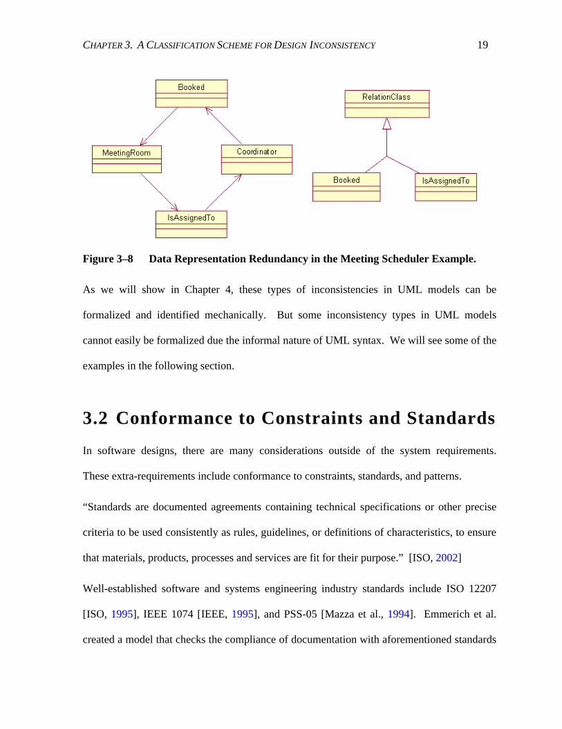
Example 3.4 Representation of the relation between MeetingRoom and Coordinator.
The MeetingRoom class object is associated to the Coordinator class object via the
IsAssignedTo class object. The inverse association is represented by the Booked class object.
Both association classes are inherited from the same class RelationClass. In this case, a data
representation redundancy is identified. The following object diagram illustrates the details.
CHAPTER 3. A CLASSIFICATION SCHEME FOR DESIGN INCONSISTENCY 19
Figure 3–8 Data Representation Redundancy in the Meeting Scheduler Example.
As we will show in Chapter 4, these types of inconsistencies in UML models can be
formalized and identified mechanically. But some inconsistency types in UML models
cannot easily be formalized due the informal nature of UML syntax. We will see some of the
examples in the following section.
3.2 Conformance to Constraints and Standards
In software designs, there are many considerations outside of the system requirements.
These extra-requirements include conformance to constraints, standards, and patterns.
“Standards are documented agreements containing technical specifications or other precise
criteria to be used consistently as rules, guidelines, or definitions of characteristics, to ensure
that materials, products, processes and services are fit for their purpose.” [ISO, 2002]
Well-established software and systems engineering industry standards include ISO 12207
[ISO, 1995], IEEE 1074 [IEEE, 1995], and PSS-05 [Mazza et al., 1994]. Emmerich et al.
created a model that checks the compliance of documentation with aforementioned standards

CHAPTER 3. A CLASSIFICATION SCHEME FOR DESIGN INCONSISTENCY 20
[Emmerich et al., 1999]. In addition to such industry standards, there are corporate standards,
best practices in software design, and well-established patterns. In sections 3.2.1-3.2.3, we
describe constraints that arise from intra-system conflicts, inter-system mismatches, and the
UML modeling language. In section 3.2.4, we describe an example of best-practice design
standards. In section 3.2.5, we describe two examples of conformance to design patterns.
3.2.1 Intra-system Conflicts
Intra-system conflicts can result when two required properties of the system cannot be
satisfied simultaneously. The conflict can either be between a local condition and a global
condition, between local conditions, or between global conditions.
For example, in an elevator design, a safety condition states that if the sensor of a lift senses a
passenger coming through the door, it keeps the door open. As a performance constraint, the
overall system requires all lifts to close the door within 10 seconds. In this example, the
precondition of the door module can not be satisfied under the global constraint. A conflict
between the local condition and the global constraint may result.
3.2.2 Inter-system Mismatches
Reuse of existing systems or off-the-shelf components is an important aspect of modern
software engineering. But systems are built by different teams of different corporations
using different processes and designs. Often times, two systems have incompatibility either
in the interface, assumptions about the environment, or the pre- and post-conditions of each
computation unit. Such issues are easier to identify and resolve at the design level rather
than program level.

CHAPTER 3. A CLASSIFICATION SCHEME FOR DESIGN INCONSISTENCY 21
Using the same elevator design example, suppose we have completed the design of
individual lifts and purchased an off-the-shelf central control unit, during the integration
phase, we found out that the central control unit requires each lift to keep a queue of locally
received requests. However, in our lift design, we assumed that the central control unit will
keep all requests in the central request queues. In this example, we have an inter-system
mismatch in the assumptions of the environment5.
3.2.3 Constraints of Modeling Languages
In the Unified Modeling Language (UML), the constraints are specified by the Object
Constraint Language (OCL) [OMG, 2000a]. A few examples from the UML Foundation and
Core Constraint Set presented in [Nentwich et al., 2001a] are included below.
1. The AssociationEnds must have a unique name within the Association.
2. No Attributes may have the same name within a Classifier.
3. At most one AssociationEnd may be an aggregation or composition.
3.2.4 Design Standards
In many development cultures, there is a requirement of conformance to best practices,
industry standards, and corporate standards. The standards vary from team to team, and
corporation to corporation. It is important to enforce the standards in the design practice. In
this section, we describe an example of a best-practice design standard. In Chapter 4, we
5 Note that the central control unit is part of the environment for the lifts, and vice versa.

CHAPTER 3. A CLASSIFICATION SCHEME FOR DESIGN INCONSISTENCY 22
describe the rule that can detect deviations from the standard via inconsistency checks.
Designers can use the inconsistency results to reveal violations of the standard.
A well known object-oriented design standard is the Law of Demeter, which states that
“The methods of a class should not depend in any way on the structure of any class, except
the immediate (top-level) structure of their own class. Further, each method should send
messages to objects belonging to a very limited set of classes only.” [Sakkinen, 1988]
Booch’s interpretation of this law is “The basic effect of applying this Law is the creation of
loosely coupled classes, whose implementation secrets are encapsulated. Such classes are
fairly unencumbered, meaning that to understand the meaning of one class, you need not
understand the details of many other classes.” [Booch, 1994]
Rumbaugh’s interpretation of the law is: “Avoid traversing multiple links or methods. A
method should have limited knowledge of an object model. A method must be able to traverse
links to obtain its neighbors and must be able to call operations on them, but it should not
traverse a second link from the neighbor to a third class.” [Rumbaugh et al., 1991]
We illustrate the violation of this design concept by a simple library example.
Example 3.5 Locate book copies in a library.
A borrower is trying to locate copies of a book by a known author. The borrower asks the
librarian to find the book by its unique call number, and uses the record of the book to locate
the copies of the book. It can be represented in Java code as the following:
class Borrower {… getLibrarian().findBookByCallNumber().listCopies();
…}

CHAPTER 3. A CLASSIFICATION SCHEME FOR DESIGN INCONSISTENCY 23
A sequence diagram of the example is included in Figure 3–9. The violation here is that the
Borrower should not be traversing the links to a BookRecord provided by the Librarian in
order to receive services provided by the BookRecord.
Figure 3–9 Violation of the Law of Demeter – Library example
To fix the violation of the Law of Demeter in the above scenario, we can add a service
provided by the Librarian to the design which returns a list of book copies for a given call
number. Figure 3–10 shows the corrected Sequence Diagram.
Figure 3–10 Correction to the Violation of the Law of Demeter – Library Example

CHAPTER 3. A CLASSIFICATION SCHEME FOR DESIGN INCONSISTENCY 24
3.2.5 Design Patterns
Software design patterns are well known both in the literature and in practice. To be able to
use these, a designer must study them in depth and determine which pattern is applicable to
the problem in hand. This can be a difficult task. In particular, misuses can be introduced
due to misunderstanding and misinterpretation of the pattern. Therefore, we would like to
provide automated assistance to designers in recognizing the patterns used in designs, and
point out the inconsistent usage of the patterns.
In order to achieve this, we use specific characteristics of known design patterns to determine
whether a pattern is used in the design process and make further suggestions according to the
pattern. The recognition of a design pattern involves formalization of its distinctive
characteristics, which is given in Chapter 4 using production rules.
Two examples from [Gamma et al., 1995] are included below.
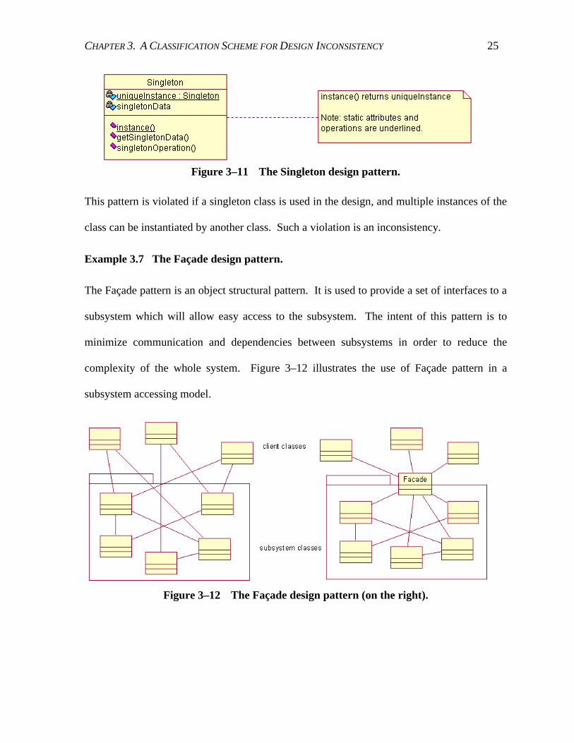
Example 3.6 The Singleton design pattern.
The Singleton pattern is an object creational pattern. It ensures the designated class has only
one instance and is able to provide a global access point to the instance. It can be used when
multiple instances of a class are prohibited in a system, or to preclude the unnecessary object
instantiations of a class. For example, a system can have many printers, but should only have
one printer spooler. Moreover, the Singleton class is responsible for providing access to the
reference to the instance. Figure 3–11 shows a class diagram of a Singleton class.
CHAPTER 3. A CLASSIFICATION SCHEME FOR DESIGN INCONSISTENCY 25
Figure 3–11 The Singleton design pattern.
This pattern is violated if a singleton class is used in the design, and multiple instances of the
class can be instantiated by another class. Such a violation is an inconsistency.
Example 3.7 The Façade design pattern.
The Façade pattern is an object structural pattern. It is used to provide a set of interfaces to a
subsystem which will allow easy access to the subsystem. The intent of this pattern is to
minimize communication and dependencies between subsystems in order to reduce the
complexity of the whole system. Figure 3–12 illustrates the use of Façade pattern in a
subsystem accessing model.
Figure 3–12 The Façade design pattern (on the right).

CHAPTER 3. A CLASSIFICATION SCHEME FOR DESIGN INCONSISTENCY 26
If a class diagram of a design resembles the diagram on the left, a Façade pattern can be
employed. If the use of the Façade pattern is appropriate in the design, then the absence of a
façade is inconsistent with this practice.
3.3 Change
A software design may undergo numerous changes before completion, due to change
requests, performance tuning, and correction of environment assumptions. During the
process of making design changes, inconsistencies may easily be introduced. Below, we
describe two instances of design changes that cause inconsistencies.
3.3.1 Edit Blocks
One source of inconsistency is in the use of edit blocks in making changes. An edit block is
a group of edit steps required to complete a desired change to the design model. If the steps
are not performed as one group, it is possible that some steps may be missed, thus putting the
design model in an inconsistent state. For example, we may want to replace all of the
occurrences of an abstract class with its subclass in an UML model. If this change is not
performed as an atomic action, the model will be inconsistent until the edit block is
completed.
3.3.2 Design Model Transformation
Another source of inconsistency from change is in transforming a design model from one
representation form to another. When changes are made incrementally by hand, the system
will remain in an inconsistent state during the entire modification process. If an unrelated

CHAPTER 3. A CLASSIFICATION SCHEME FOR DESIGN INCONSISTENCY 27
change request is received during this process, then either the new request has to be put on
hold until the modification is complete, or new inconsistencies will be introduced to the
model. One example of a design model transformation is to convert a design represented in
UML to one in an architectural description language, e.g., Rapide [Luckham, 1996].
In this chapter, we have described a classification scheme for design inconsistencies, and
provided examples for each class. Table 3-1 summarizes each inconsistency type and
indicates those that are formalized in Chapter 4.
Table 3-1 Summary of Inconsistency Types
NAME OF THE INCONSISTENCY FORMALIZED Redundancy in Design Representation Yes Redundancy in Data Representation No Intra-system Conflicts No Inter-system Mismatches No Constraints of Modeling Languages Yes Design Standards Yes Design Patterns Yes Edit Blocks No Design Model Transformation No
For simplicity, the formalization of Redundancy in Data Representation is omitted. The
other four types are not formalized due to limited expressiveness of UML. In the next
chapter, we will describe the formalization and identification of the selected inconsistencies.

28
Chapter 4
I nconsistency I denti f icat ion
We have introduced a classification scheme of generally occurring design inconsistencies. In
this chapter, we propose a solution for identifying these inconsistencies automatically. In
particular, we will focus on those inconsistency classes introduced in Chapter 3 that are
modeled in UML.
First, we introduce production systems, algorithms and applications. Next, we define the
UML constructs and inconsistency rules using production system language. Finally, we
demonstrate the application of production system technique on a design example.
4.1 Pr oduct ion Systems 6
A production system is a reasoning system that uses forward-chaining derivation techniques.
It uses rules, called production rules or productions in short, to represent its general
knowledge, and keeps an active memory of facts (or assertions) known as the working
memory (WM).
A production rule is usually written in the following form:
6 The definitions, algorithms and examples in this section are adopted from [Brachman and Levesque, 2001].

CHAPTER 4. INCONSISTENCY IDENTIFICATION 29
I F conditions Then actions
The antecedent conditions, also known as patterns, are tests that are to be applied against the
current state of the WM. They are partial descriptions of working memory elements. If the
conditions are satisfied by some elements, the consequent actions are fired to modify the
WM. The basic operation of a production system is a cyclic application of the following
three steps in order until no more rules can be applied:
1. recognize: identify applicable rules whose antecedent conditions are satisfied by the
current WM;
2. resolve conflict: among all applicable rules (known as the conflict set), choose one to
execute;
3. act: modify the WM by applying the action given in the consequent of the executed rule.
More efficient algorithms that perform the basic operations of production systems include
RETE [Forgy, 1982]. RETE matches applicable rules by setting up a network that allows
new working memory elements to pass incrementally for testing.
4.1.1 Wor king M emor y
Working memory consists of a set of working memory elements (WMEs) each has the
following form,
( t ype at t r i but e1: val ue1 … at t r i but en: val uen) ,
where t ype, at t r i but ei , and val uei are all atoms. Each WME can be interpreted as an
existential sentence:
∃ x ⋅ [ t ype( x) ∧ at t r i but e1( x) = val ue1 ∧ … ∧ at t r i but en( x) = val uen]

CHAPTER 4. INCONSISTENCY IDENTIFICATION 30
4.1.2 Pr oduct ion Rules
The antecedent of a production rule is a set of conditions, or patterns. Each condition can be
either positive or negative. A negative condition is of the form –cond. The body of a
positive condition is composed of the following tuple:
( t ype at t r i but e1: speci f i cat i on1 . . . at t r i but en: speci f i cat i onn) ,
where each specification can be one of the following:
• an atom, including a string within “ ” , a word, a numeral
• a variable, denoted in italic letters
• an evaluation expression, within [], including arithmetic, string manipulation
• a test, within { } , including <, >, =, �
• the conjunction (∧), disjunction (∨), or negation (¬) of a specification.
A rule is applicable if all of the variables can be evaluated using the WMEs in the current
WM such that the conditions are met. A positive condition is satisfied if there is a matching
WME in the WM; a negative condition is satisfied if there is no matching WME in the WM.
Production rules are stored in the production memory of the system.
4.1.3 Conf l ict Resolut ion
To resolve conflicts among all applicable rules, there are two general approaches. In a data-
directed context, all applicable rules can be fired to obtain all consequences. In a goal-
directed context, only one rule is selected to fire which allows a single method to be pursued.
There are a number of standard ways for selecting a rule:
1. Randomness: select a rule at random.

CHAPTER 4. INCONSISTENCY IDENTIFICATION 31
2. Order: choose the first rule in order of presentation. (This can be modified to use
priority scheme for the selection.)
3. Specificity: select a rule whose conditions are most specific. Rule A is said to be
more specific than rule B if the conditions of B is a subset of that of A.
4. Recency: choose a rule based on how recently it has been used.
5. Hierarchical: a combination of a few of above selection schemes in hierarchical
levels since after applying a single scheme, more than one rule may still be applicable.
4.1.4 Appl icat ions and Advantages
Production systems are commonly used in practice to solve complex problems. Well known
applications include MYCIN and XCON, where MYCIN was developed at Stanford with
approximately 500 production rules for recognizing about 100 infections in assisting
physicians in the diagnosis of such bacterial infections, and XCON was developed by the
researchers at Carnegie-Mellon for the Digital Equipment Corporation in configuring
computers.
Among other major advantages of production system, we wish to present the following key
advantages. They are modularity, since each rule works independently of others in the
system; simple control structures, the controls are embedded in the productions rules, not the
algorithm; transparency, terminology used to describe the production rules are usually
derived from expert knowledge or based on observations of expert behavior, which makes it
easy for humans to interpret; dynamics, production rules can be added, deleted, or modified
by one another on the fly, and chained to achieve combinations of checks and actions. These

CHAPTER 4. INCONSISTENCY IDENTIFICATION 32
are the main reasons why we choose to use this approach to solve inconsistency problems in
software designs.
4.2 I nconsistency I dent i f icat ion Using
Pr oduct ion System
In this section, we present the details of the application of production system on automating
identification and resolution of inconsistencies from UML design models. First, we
introduce the general mechanism of the method. Next, we define working memory elements
for UML constructs and inconsistency resolution elements. For our purpose, we also define
four types of rules: the inconsistency rules that identify inconsistent designs; the resolution
rules that respond to user’s choice of fix; the cleanup rules that remove expired inconsistency
working memory elements and the corresponding To-Do items; and orphan control rules that
remove working memory elements with invalid parent identification (pid). Then, we
describe dynamic controls of these production rules. Finally, we use a design example to
illustrate the application of the method.
4.2.1 The Gener al M echanism of the M ethod
When changes are made to the working memory, the antecedent conditions of all of the rules
will be tested for applicability. Among all of the applicable rules in the conflict set, one will
be selected each time to execute. According to the consequent action of the selected rule,
more changes will be made to the working memory. There are four scenarios, one for each
type of rules.

CHAPTER 4. INCONSISTENCY IDENTIFICATION 33
Scenario 1 If the selected rule is an inconsistency rule, an inconsistency WME is added to
the WM with location of the occurrence and user choices of resolution (if applicable).
The inconsistency notification mechanism is similar to that of Argo/UML [Robbins and
Redmiles, 1998], in that a To Do item is added to the to-do list of the user. The user is
responsible to review the delivered message and initiate a resolution action. If the user
chooses a recommended resolution and provides required input data, new WMEs are
added accordingly. (Note that the inconsistency notification and resolution input are not
part of the production system, but a part of the interface between the production system
and the design modeling tool.) The cycle of the production system restarts.
Scenario 2 If the selected rule is a resolution rule, the actions of the rule will be carried
out and the cycle restarts.
Scenario 3 If the selected rule is a cleanup rule, the pertinent inconsistency WME will be
removed from the working memory. In addition, a notification of the change will be sent
to the editor so that the associated To-Do item is removed from the To-Do List. The
cycle restarts.
Scenario 4 If the selected rule is an orphan control rule, the action of the rule will be
executed to remove the orphan elements. The cycle restarts.
4.2.2 Def ini t ions for Wor king M emor y Elements
We saw previously that a general WME is represented as the following:
( t ype at t r i but e1: val ue1 … at t r i but en: val uen)

CHAPTER 4. INCONSISTENCY IDENTIFICATION 34
In order to represent specific knowledge of UML models, we have added the following
additional notations. A pair of < > brackets enclose the acceptable values or types of values.
If the text in the < > brackets is italic, it simply describes the requirement of the value for
the given attribute. If the text in the < > brackets is r egul ar , it provides the actual values
that are available for the attribute, and choices among different values are separated by / .
The composition relation between two elements (e.g., a class and its method are regarded as
the parent and child respectively) is represented only in the child clause via pi d, since each
child has only one parent, but each parent element may have more than one child and the
representation of multi-values is not supported by the production system syntax. When the
pi d of a clause (A) matches to the i d of another clause (B), A is interpreted as part of B, or
child of B.
Class Diagram, Class
( cl assDi agr am i d: <unique id> name: <string> not es: <long string>)
( cl ass i d: <unique id> pi d: <class diagram id> name: <string>)
( met hod i d: <unique id> pi d: <class id> name: <string>)
( par amet er i d: <unique id> pi d: <method id> name: <string>
t ype: <class name>)
( at t r i but e i d: <unique id> pi d: <class id> name: <string> t ype: <class id>
scope: <publ i c/ pr i vat e/ def aul t / pr ot ect ed)
Associat ion
( associ at i on i d: <unique id> name: <optional>)
( associ at i onEnd i d: <unique id> name: <optional>
pi d: <association id> endi d: <id of the associated element>
t ype: <gener al i zat i on/ r eal i zat i on/ dependency/ associ at i on>)

CHAPTER 4. INCONSISTENCY IDENTIFICATION 35
State Diagram
( st at e i d: <unique id> name: <optional> speci f i cat i on: <string>)
( t r ansi t i on i d: <unique id> f r om: <state id1> t o: <state id2>)
Sequence Diagram
( sequenceDi agr am i d: <unique id> name: <optional> not es: <long string>
associ at eTo: <use case ID>)
( sequenceObj ect i d: <unique id> pi d: <seq diagram id>
name: <object name or variable name> cl ass: <class name>
sequenceNumber : <number in the sequence>)
( sequenceMessage i d: <unique id> pi d: <seq diagram id> name: <message name>
msgNum: <the sequence number of the msg>
f r om: <originated object name> t o: <designated object name>
t ype: <sync/ async/ dest r oy/ r et ur n/ new>)
Inconsistency Resolut ion Elements
For each inconsistency rule, if the condition is satisfied, one or more inconsistency working
memory elements are added to the working memory. The i nconsi st ency and l ocat or
types are the main inconsistency working memory elements, which indicate the occurrence
of an inconsistency in a design and the location information of the involved design elements.
The user choi ce type of element is optional, and provides choices to the user in order to
guide the resolution of the inconsistency. The user i nput type is the resolution option that
the user has chosen, and will be used in resolving the associated inconsistency.
( i nconsi st ency i d: <unique id> name: <optional> msg: <text>
r ul ei d: <id of the offending rule>)
( l ocat or i d: <unique id> pi d: <inconsistency id>
l ocat i on: <id of the offending element>
t ype: <type of the offending element>)
( user choi ce i d: <unique id> pi d: <inconsistency id>
act i on: <add/ r emove/ modi f y>
t ar get I D: <id of the offending element>)

CHAPTER 4. INCONSISTENCY IDENTIFICATION 36
( user i nput i d: <unique id> pi d: <inconsistency id>
act i on: <add/ r emove/ modi f y>
t ar get I D: <id of the offending element>)
4.2.3 I nconsistency Rules
In this section, we define production rules for the inconsistency classes identified in Chapter
3. Each rule has a description in text and formalization in production system language
defined above. The description of each rule characterizes the consistency requirement of
design models, but the formalization of the antecedent condition of a rule captures the
violation of the requirement, i.e., the inconsistent modeling. For example, if a constraint
requires condition A to be true in a design, then the description of the production rule
describes the condition A, but the formalization of the rule describes the actions to be taken
in case of violation of the condition A.
The consequent action of a rule usually adds inconsistency resolution elements which include
a message about the inconsistency, the location of each modeling elements involved, and one
or more choices of resolution. In general, resolution choices are not always definable a priori.
Many inconsistency resolutions rely heavily on the context of the problem domain. In the
rule definitions below, we include only the resolution choices for those inconsistencies which
have standard solutions independent of the specific problem domain. Domain specific
resolutions can be added to individual rules a posteriori via customized function calls.
Naming Inconsistency between Behav io ral and St ructu ral Diagrams
Description: Any object and message used in a Sequence Diagram must have correspondence
in a Class Diagram.

CHAPTER 4. INCONSISTENCY IDENTIFICATION 37
Rule 1: An object of a behavioral diagram is undefined in class diagrams.7
I F ( sequenceDi agr am i d: x name: n)
( sequenceObj ect i d: y pi d: x c l ass: j)
- ( cl ass name: j)
THEN ADD ( i nconsi st ency i d: [ newI d( ) ] ∧{ =s} name: ” Nami ng- 1”
msg: ” An obj ect i n t he sequence di agr am has not been
def i ned i n any cl ass di agr ams. ” )
( l ocat or i d: [ newI d( ) ] pi d: s l ocat i on: x t ype: sequenceDi agr am name: n)
( l ocat or i d: [ newI d( ) ] pi d: s l ocat i on: y t ype: sequenceObj ect name: j)
Rule 2: A message of a behavioral diagram is undefined in the corresponding class
definition.
I F ( sequenceDi agr am i d: x name: j)
( sequenceMessage i d: m pi d: x name: y t o: z)
( c l assDi agr am i d: d name: g)
( c l ass i d: c pi d: d name: z)
- ( met hod pi d: c name: y)
THEN ADD ( i nconsi st ency i d: [ newI d( ) ] ∧{ =s} name: ” Nami ng- 2”
msg: ” A message of a behavi or al di agr am i s undef i ned i n
t he cor r espondi ng cl ass def i ni t i on. ” )
( l ocat or i d: [ newI d( ) ] pi d: s l ocat i on: x t ype: sequenceDi agr am name: j)
( l ocat or i d: [ newI d( ) ] pi d: s l ocat i on: m t ype: sequenceMessage name: y)
( l ocat or i d: [ newI d( ) ] pi d: s l ocat i on: d t ype: cl assDi agr am name: g)
( l ocat or i d: [ newI d( ) ] pi d: s l ocat i on: c t ype: cl ass name: z)
Rule 3: A message has a parameter that is absent from its correspondence in the class
diagram.
I F ( sequenceDi agr am i d: x name: j)
( sequenceMessage i d: m pi d: x name: y t o: z)
( par amet er i d: p pi d: m t ype: t name: a)
7 The inconsistency ids must be unique, and can be predetermined or generated.

CHAPTER 4. INCONSISTENCY IDENTIFICATION 38
(classDiagram id:d name:g)
(class id:c pid:d name:z)
(method id:e pid:c name:y)
-(parameter pid:e type:t)
THEN ADD (inconsistency id:[newId()]∧{=s} name:”Naming-3”
msg:”A message has a parameter that is absent from its
correspondence in the class diagram.”)
(locator id:[newId()] pid:s location:x type:sequenceDiagram name:j)
(locator id:[newId()] pid:s location:m type:sequenceMessage name:y)
(locator id:[newId()] pid:s location:p type:parameter name:a)
(locator id:[newId()] pid:s location:d type:classDiagram name:g)
(locator id:[newId()] pid:s location:c type:class name:z)
(locator id:[newId()] pid:s location:e type:method name:y)
Rule 4: A message is missing a parameter whose correspondence exists in the class diagram.
IF (sequenceDiagram id:x name:j)
(sequenceMessage id:m pid:x name:y to:z)
-(parameter pid:m type:t)
(classDiagram id:d name:g)
(class id:c pid:d name:z)
(method id:e pid:c name:y)
(parameter id:p pid:e name:a type:t)
THEN ADD (inconsistency id:[newId()]∧{=s} name:”Naming-2”
msg:”A parameter is missing from a message, whose
correspondence exists in the class diagram.”)
(locator id:[newId()] pid:s location:x type:sequenceDiagram name:j)
(locator id:[newId()] pid:s location:m type:sequenceMessage name:y)
(locator id:[newId()] pid:s location:d type:classDiagram name:g)
(locator id:[newId()] pid:s location:c type:class name:z)
(locator id:[newId()] pid:s location:e type:method name:y)
(locator id:[newId()] pid:s location:p type:parameter name:a)
Feature Dependence – Specialization
Description: In describing features using Sequence Diagrams, if feature A is a specialization
of feature B illustrated in the corresponding diagrams, then an inconsistency occurs if a

CHAPTER 4. INCONSISTENCY IDENTIFICATION 39
message or object, that appears in B’s diagram, is absent from that of A. Note that in some
instances, this inconsistency may be considered spurious.
Rule 1: An object is absent.
I F ( usecaseAssoci at i on i d: a t ype: gener al i zat i on par ent : u chi l d: w)
( sequenceDi agr am i d: x usecaseI D: u)
( sequenceDi agr am i d: y usecaseI D: w)
( sequenceObj ect i d: o pi d: x name: n)
- ( sequenceObj ect pi d: y name: n)
THEN ADD ( i nconsi st ency i d: [ newI d( ) ] ∧ { =s}
msg: ” An obj ect i s mi ssi ng f r om t he sequence di agr am of
t he speci al i zed use case. ” )
( l ocat or i d: [ newI d( ) ] pi d: s l ocat i on: o t ype: sequenceObj ect )
( l ocat or i d: [ newI d( ) ] pi d: s l ocat i on: x t ype: sequenceDi agr am)
( l ocat or i d: [ newI d( ) ] pi d: s l ocat i on: y t ype: sequenceDi agr am)
( l ocat or i d: [ newI d( ) ] pi d: s l ocat i on: u t ype: usecase)
( l ocat or i d: [ newI d( ) ] pi d: s l ocat i on: w t ype: usecase)
Rule 2: A message is absent.
I F ( sequenceDi agr am i d: x usecaseI D: u)
( sequenceDi agr am i d: y usecaseI D: w)
( usecaseAssoci at i on i d: a t ype: gener al i zat i on par ent : u chi l d: w)
( sequenceMessage i d: m pi d: x name: n)
- ( sequenceMessage pi d: y name: n)
THEN ADD ( i nconsi st ency i d: [ newI d( ) ] ∧ { =s}
msg: ” A message i s mi ssi ng f r om t he sequence di agr am of
t he speci al i zed use case. ” )
( l ocat or i d: [ newI d( ) ] pi d: s l ocat i on: m t ype: sequenceMessage)
( l ocat or i d: [ newI d( ) ] pi d: s l ocat i on: x t ype: sequenceDi agr am)
( l ocat or i d: [ newI d( ) ] pi d: s l ocat i on: y t ype: sequenceDi agr am)
( l ocat or i d: [ newI d( ) ] pi d: s l ocat i on: u t ype: usecase)
( l ocat or i d: [ newI d( ) ] pi d: s l ocat i on: w t ype: usecase)

CHAPTER 4. INCONSISTENCY IDENTIFICATION 40
Feature Interference
Description: When two features have overlapping specifications, conflicting states may be
reached simultaneously.
Rule 1: Conflicting states are reachable simultaneously in State Diagrams.
IF (state id:x name:n1)
(state id:y ∧ {?x} name:n2 specification:B)
(state id:z ∧ {?x} name:n3 specification:{⇒ ¬B})
(transition id:a from:x to:y)
(transition id:b from:x to:z)
THEN ADD (inconsistency id:[newId()] ∧ {=s} ruleid:”FI-1”
msg:”Conflicting states occur simultaneously in state diagrams.”)
(locator id:[newId()] pid:s location:x type:state)
(locator id:[newId()] pid:s location:y type:state)
(locator id:[newId()] pid:s location:z type:state)
UML Constraints
Description: UML Constraints are defined in Object Constraint Language (OCL)
[OMG, 2000a]. To demonstrate the applicability, we present the examples used in Chapter 3.
Rule 1: The AssociationEnds must have a unique name within the Association.
IF (association id:t)
(associationEnd id:x name:z pid:t)
(associationEnd id:y ∧ {?x} name:z pid:t)
THEN ADD (inconsistency id:[newId()] ∧ {=s} ruleid:”UML-1”
msg:”AssociationEnd must be unique within an Association class”)
(locator id:[newId()] pid:s location:t type:association)
(locator id:[newId()] pid:s location:x type:associationEnd)
(locator id:[newId()] pid:s location:y type:associationEnd)
(userchoice id:[newId()] pid:s action:remove targetID:t)
(userchoice id:[newId()] pid:s action:modify targetID:x)
(userchoice id:[newId()] pid:s action:modify targetID:y)

CHAPTER 4. INCONSISTENCY IDENTIFICATION 41
Rule 2: No Attributes may have the same name within a Classifier.
I F ( at t r i but e i d: x name: z pi d: t)
( at t r i but e i d: y ∧ { � x} name: z pi d: t)
THEN ADD ( i nconsi st ency i d: [ newI d( ) ] ∧{ =s} r ul ei d: ” UML- 2”
msg: ” At t r i but es must be uni que wi t hi n a cl ass. ” )
( l ocat or i d: [ newI d( ) ] pi d: s l ocat i on: x t ype: at t r i but e)
( l ocat or i d: [ newI d( ) ] pi d: s l ocat i on: y t ype: at t r i but e)
( user choi ce i d: [ newI d( ) ] pi d: s act i on: modi f y t ar get I D: x)
( user choi ce i d: [ newI d( ) ] pi d: s act i on: r emove t ar get I D: x)
( user choi ce i d: [ newI d( ) ] pi d: s act i on: modi f y t ar get I D: y)
( user choi ce i d: [ newI d( ) ] pi d: s act i on: r emove t ar get I D: y)
Rule 3: At most one AssociationEnd may be an aggregation or composition.
I F ( associ at i on i d: t)
( associ at i onEnd i d: x pi d: t aggr egat i on: yes)
( associ at i onEnd i d: y ∧ { � x} pi d: t aggr egat i on: yes)
THEN ADD ( i nconsi st ency i d: [ newI d( ) ] ∧{ =s} r ul ei d: ” UML- 3”
msg: ” At most one Associ at i onEnd may be an aggr egat i on or
composi t i on. ” )
( l ocat or i d: [ newI d( ) ] pi d: s l ocat i on: x t ype: associ at i onEnd)
( l ocat or i d: [ newI d( ) ] pi d: s l ocat i on: y t ype: associ at i onEnd)
( l ocat or i d: [ newI d( ) ] pi d: s l ocat i on: t t ype: associ at i on)
( user choi ce i d: [ newI d( ) ] pi d: s act i on: r emove t ar get I D: x)
( user choi ce i d: [ newI d( ) ] pi d: s act i on: r emove t ar get I D: y)
( user choi ce i d: [ newI d( ) ] pi d: s act i on: r emove t ar get I D: t)
Standards Confo rmance Rules
Description: Standards conformance rules are defined to ensure specific design standards are
followed in the design model.

CHAPTER 4. INCONSISTENCY IDENTIFICATION 42
Rule 1: A design model should obey the Law of Demeter8.
I F ( sequenceMessage i d: m1 r et ur n: b pi d: p)
( sequenceObj ect name: b t ype: L pi d: p)
( sequenceMessage i d: m2 ∧{ ≠m1} t o: L r et ur n: c pi d: p)
( sequenceObj ect name: c t ype: K pi d: p)
( sequenceMessage i d: m3 ∧{ ≠m1} ∧{ ≠m2} t o: K pi d: p)
THEN ADD ( i nconsi st ency i d: [ newI d( ) ] ∧{ =s}
msg: ” Vi ol at i on of t he Law of Demet er . ” )
( l ocat or i d: [ newI d( ) ] pi d: s l ocat i on: m1 t ype: sequenceMessage)
( l ocat or i d: [ newI d( ) ] pi d: s l ocat i on: m2 t ype: sequenceMessage)
( l ocat or i d: [ newI d( ) ] pi d: s l ocat i on: m3 t ype: sequenceMessage)
( l ocat or i d: [ newI d( ) ] pi d: s l ocat i on: b t ype: sequenceObj ect )
( l ocat or i d: [ newI d( ) ] pi d: s l ocat i on: c t ype: sequenceObj ect )
Pattern Recogn it ion Ru les
Description: The antecedent condition of a pattern recognition rule formalizes one distinctive
characteristic of the pattern and describes the violation of its usage.
Rule 1: When a Singleton pattern is used in a design, no other class objects should keep a
reference to the singleton class object.
(Note that a Singleton pattern is recognized if the class has a static method returning an
instance of the class and a static attribute that stores instances of this class.)
I F ( cl ass i d: c1 name: cn1)
( met hod i d: m pi d: c1 r et ur n: cn1 modi f i er : ” st at i c” )
( at t r i but e i d: a1 pi d: c1 t ype: cn1 modi f i er : ” st at i c” )
( at t r i but e i d: a2 pi d: c2 ∧ { ≠c1} t ype: cn1)
THEN ADD ( i nconsi st ency i d: [ newI d( ) ] ∧{ =s}
msg: ” Ref er ence t o t he obj ect of a si ngl et on cl ass shoul d
8 See page 21.

CHAPTER 4. INCONSISTENCY IDENTIFICATION 43
not be st or ed i n any ot her cl asses. ” )
( l ocat or i d: [ newI d( ) ] pi d: s l ocat i on: c1 t ype: cl ass)
( l ocat or i d: [ newI d( ) ] pi d: s l ocat i on: m t ype: met hod)
( l ocat or i d: [ newI d( ) ] pi d: s l ocat i on: a2 t ype: at t r i but e)
Rule 2: When multiple classes in a package are accessed from outside the package, a Façade
pattern can be used and a Façade class should be placed as a common interface to the
package.
I F ( cl ass i d: c1 package: p1)
( c l ass i d: c2∧{ ≠c1} package: p2∧{ ≠p1} )
( associ at i onEnd pi d: a1 endi d: c1 )
( associ at i onEnd pi d: a1 endi d: c2 )
( c l ass i d: c3∧{ ≠c1} package: p1)
( c l ass i d: c4∧{ ≠c2} package: p3∧{ ≠p1} )
( associ at i onEnd pi d: a2 endi d: c3 )
( associ at i onEnd pi d: a2 endi d: c4 )
THEN ADD ( i nconsi st ency i d: [ newI d( ) ] ∧{ =s}
msg: ” A Façade cl ass can be used as a common i nt er f ace t o
package { p1} . ” )
( l ocat or i d: [ newI d( ) ] pi d: s l ocat i on: p1 t ype: package)
4.2.4 Resolut ion Rules
Resolution rules are used to automatically resolve inconsistency identified in design models
upon receiving of user choices after an inconsistency notice is delivered. In general, a
resolution rule corresponds to a single user choice in response to an inconsistency
notification, therefore, each inconsistency rule may have multiple resolution rules defined.
We demonstrate the definition and application of resolution rules on two inconsistency rules
which have well-defined actions. Rules 1-1 and 1-2 below correspond to the UML
Constraints Rule 1, and rules 2-1 and 2-2 correspond to the UML Constraints Rule 2.

CHAPTER 4. INCONSISTENCY IDENTIFICATION 44
Rule 1-1: Modify the name of the AssociationEnd.
I F ( associ at i onEnd i d: x)
( i nconsi st ency i d: s)
( user choi ce pi d: s act i on: modi f y t ar get I D: x
t ar get Type: associ at i onEnd at t r i but e: name)
( user i nput pi d: s act i on: modi f y t ar get I D: x
at t r i but e: name val ue: v)
THEN MODI FY 1 ( name v)
REMOVE 2, 3, 4
Rule 1-2: Remove the Association completed.
I F ( associ at i on i d: t)
( i nconsi st ency i d: s)
( user choi ce pi d: s act i on: r emove t ar get I D: t
t ar get Type: associ at i on)
( user i nput pi d: s act i on: r emove t ar get I D: t)
THEN REMOVE 1, 2, 3, 4
Rule 2-1: Modify the name of the Attribute.
I F ( at t r i but e i d: x name: z)
( i nconsi st ency i d: s)
( user choi ce pi d: s act i on: modi f y t ar get I D: x
t ar get Type: at t r i but e at t r i but e: name)
( user i nput pi d: s act i on: modi f y t ar get I D: x
at t r i but e: name val ue: v)
THEN MODI FY 1 ( name v)
REMOVE 2, 3, 4
Rule 2-2: Remove the Attribute.
I F ( at t r i but e i d: x name: z)
( i nconsi st ency i d: s)
( user choi ce pi d: s act i on: modi f y t ar get I D: x
t ar get Type: at t r i but e at t r i but e: name)
( user i nput pi d: s act i on: r emove t ar get I D: x)
THEN REMOVE 1, 2, 3, 4

CHAPTER 4. INCONSISTENCY IDENTIFICATION 45
4.2.5 Cleanup Rules
Cleanup rules are used to remove expired inconsistency working memory elements from the
WM, thus keeping the inconsistency messages valid with respect to the current model. For
every inconsistency rule, there is an associated cleanup rule. This rule checks whether the
negation of the antecedent of the corresponding inconsistency rule is true, and whether the
inconsistency WME exists in the WM. If both are true, the cleanup rule may be executed to
remove the infeasible inconsistency working memory element. To illustrate the form of this
type of rules, only a selected set of inconsistency rules are used. Cleanup rules for the other
inconsistency rules can be written in the similar fashion. Rule 1 through 3 below
corresponds to the UML Constraints Rule 1 to 3.
Rule 1: Remove inconsistency WME if the AssociationEnds have unique names within the
Association.
I F ( i nconsi st ency i d: s r ul ei d: ” UML- 1” )
( l ocat or pi d: s l ocat i on: x)
( l ocat or pi d: s l ocat i on: y)
( l ocat or pi d: s l ocat i on: t)
( associ at i onEnd i d: x name: z pi d: t)
( associ at i onEnd i d: y name: w ∧ { ≠z} pi d: t)
( associ at i on i d: t)
THEN REMOVE 1, 2, 3, 4
Rule 2: Remove inconsistency WME if no Attributes have the same name within a Classifier.
I F ( i nconsi st ency i d: s r ul ei d: ” UML- 2” )
( l ocat or pi d: s l ocat i on: x)
( l ocat or pi d: s l ocat i on: y)
( l ocat or pi d: s l ocat i on: t)
( at t r i but e i d: x name: z pi d: t)
( at t r i but e i d: y name: w ∧ { ≠z} pi d: t)

CHAPTER 4. INCONSISTENCY IDENTIFICATION 46
THEN REMOVE 1, 2, 3, 4
Rule 3: At most one AssociationEnd may be an aggregation or composition.
I F ( i nconsi st ency i d: s r ul ei d: ” UML- 3” )
( l ocat or pi d: s l ocat i on: x)
( l ocat or pi d: s l ocat i on: y)
( l ocat or pi d: s l ocat i on: t)
( associ at i onEnd i d: x pi d: t aggr egat i on: ” yes” )
( associ at i onEnd i d: y pi d: t aggr egat i on: ” no” )
( associ at i on i d: t)
THEN REMOVE 1, 2, 3, 4
4.2.6 Or phan Contr ol Rules
The production algorithm does not allow recursive removal of WMEs. Therefore, upon the
execution of a rule, orphan WMEs can be left in the WM. An orphan is a piece of working
memory element that has a parent pointer (via pid) linking to a non-existing WME in the
WM. As we rely on the hierarchical structure of the WMEs to express the relationship of
various UML design elements, the validity of the inconsistency WMEs must be maintained.
To achieve this, we define orphan control production rules to remove orphan WMEs.
Rule 1 through 3 below describes orphan removal rules for inconsistency WMEs. Similar
orphan control rules can be defined for all working memory elements.
Rule 1: Remove all user choice orphans.
I F - ( i nconsi st ency i d: s)
( user choi ce pi d: s)
THEN REMOVE 2
Rule 2: Remove all user input orphans.
I F - ( i nconsi st ency i d: s)
( user i nput pi d: s)

CHAPTER 4. INCONSISTENCY IDENTIFICATION 47
THEN REMOVE 2
Rule 3: Remove all locator orphans.
I F - ( i nconsi st ency i d: s)
( l ocat or pi d: s)
THEN REMOVE 2
4.2.7 Dynamic Contr ols
Above, we have described the production rules used to update the working memory elements
to reflect the changes in design knowledge base and inconsistency status. Another use of
production rules is to modify the applicability of existing rules on the fly. This allows the
user to enable or disable production rules during the design process. To achieve this, each of
the production rules described above must be modified to include a control specification in
the antecedent conditions. This specification has the following form:
- ( r ul e i d: <unique constant> di sabl ed: yes)
Each rule is associated with a unique constant representing its identification. If the
associated control element is present in the working memory, the antecedent of the rule is
unsatisfied, which causes the rule to be inapplicable in the current WM.
For example, the Feature Interference Rule 1 becomes the following:
I F - ( r ul e i d: ” FI - 1” di sabl ed: yes)
( st at e i d: x name: n1)
( st at e i d: y ∧ { ≠x} name: n2 speci f i cat i on: B)
( st at e i d: z ∧ { ≠x} name: n3 speci f i cat i on: { � ¬B} )
( t r ansi t i on i d: a f r om: x t o: y)
( t r ansi t i on i d: b f r om: x t o: z)
THEN ADD ( i nconsi st ency i d: [ newI d( ) ] ∧{ =s}
msg: ” Conf l i ct i ng st at es occur si mul t aneousl y i n st at e di agr ams. ” )
( l ocat or i d: [ newI d( ) ] pi d: s l ocat i on: x t ype: st at e)

CHAPTER 4. INCONSISTENCY IDENTIFICATION 48
( l ocat or i d: [ newI d( ) ] pi d: s l ocat i on: y t ype: st at e)
( l ocat or i d: [ newI d( ) ] pi d: s l ocat i on: z t ype: st at e)

49
Chapter 5
I mplementat ion
In this chapter, we describe the current implementation, RIDE (Rule-based Inconsistency
Detection Engine), by presenting the architecture of the system, an illustration of one
execution iteration on an example, analysis of the method, and implementation issues.
5.1 Ar chi tectur e
RIDE is a Java implementation which can be integrated into an existing UML Design
Environment, such as Argo/UML Editor [Argo, 2002] and Rational Rose [Rational, 2002]. It
uses Jess [Jess, 2002] — an off-the-shelf Java Rule Engine that implements the RETE
algorithm, to execute production rules. It is to be integrated with Argo/UML Editor to
perform on-the-fly inconsistency checking of UML models.
The architecture of the RIDE system is illustrated in Figure 5–1.

CHAPTER 5. IMPLEMENTATION 50
Figure 5–1 The Architecture of the RIDE System
There are three components in RIDE:
1. As both the editor and the rule engine maintain their own representations of the UML
model and inconsistency report, the Synchronizer component exists to keep them
identical. It sends changes of the editor's model to the rule engine via the Rule
Engine Abstraction Layer, and delivers inconsistency report and modifications due to
resolution by the rule engine back to the editor. Synchronizer can be thought of as an
editor specific plug-in because it understands the editor's data representation and
change notification mechanism.
2. The Rule Engine Abstraction Layer component allows replacing Jess by another
rule engine.
3. The Rule Editor component provides a user-interface which allows the user to
manage the rule base. The user can display status of rules, and add/delete/modify
rules.

CHAPTER 5. IMPLEMENTATION 51
Next, we demonstrate an end-to-end execution of inconsistency checking using Example 3.1.
5.2 Example
We demonstrate one end-to-end execution of the inconsistency identification process on
Example 3.1.
In Example 3.1, when a Meeting class is created in the UML model, the class and the two
attributes, both called time, are added to the working memory. They are represented In Jess
as the following:
( cl ass ( i d gen0) ( name meet i ng) )
( at t r i but e ( i d gen1) ( name t i me) ( pi d gen0) )
( at t r i but e ( i d gen2) ( name t i me) ( pi d gen0) )
The UML Constraint Rule 2 (UML-2) is represented in Jess as below. The complete Jess
script is attached in Appendix B.
( def r ul e uml - c2
( at t r i but e ( i d ?a1) ( name ?name) ( pi d ?pi d) )
( at t r i but e ( i d ?a2) ( name ?name) ( pi d ?pi d) )
( not ( t est ( eq ?a1 ?a2) ) )
( t est ( < ( sub- st r i ng 4 ( st r - l engt h ?a1) ?a1)
( sub- st r i ng 4 ( st r - l engt h ?a2) ?a2) ) )
=>
( bi nd ?i ( gensym* ) )
( asser t ( i nconsi st ency ( i d ?i ) ( name " uml c2" )
( msg " UML C2 i s vi ol at ed. " ) ) )
( bi nd ?l oc1 ( gensym* ) )
( asser t ( l ocat or ( i d ?l oc1) ( pi d ?i ) ( l ocat i on ?a1)
( t ar get Type at t r i but e) ) )
( bi nd ?l oc2 ( gensym* ) )
( asser t ( l ocat or ( i d ?l oc2) ( pi d ?i ) ( l ocat i on ?a2)
( t ar get Type at t r i but e) ) )

CHAPTER 5. IMPLEMENTATION 52
( bi nd ?uc1 ( gensym* ) )
( asser t ( user choi ce ( i d ?uc1) ( pi d ?i ) ( act i on modi f y)
( t ar get I D ?a1) ( t ar get Type at t r i but e) ) )
( bi nd ?uc2 ( gensym* ) )
( asser t ( user choi ce ( i d ?uc2) ( pi d ?i ) ( act i on r emove)
( t ar get I D ?a1) ( t ar get Type at t r i but e) ) )
( bi nd ?uc3 ( gensym* ) )
( asser t ( user choi ce ( i d ?uc3) ( pi d ?i ) ( act i on modi f y)
( t ar get I D ?a2) ( t ar get Type at t r i but e) ) )
( bi nd ?uc4 ( gensym* ) )
( asser t ( user choi ce ( i d ?uc4) ( pi d ?i ) ( act i on r emove)
( t ar get I D ?a2) ( t ar get Type at t r i but e) ) ) )
The second t est clause in the condition portion of rule UML-C2 ensures this rule is applied
only once for any pair of attributes.
The RETE network of UML-C2 is shown in Figure 5–2. The descriptions of working
memory changes that are passed into the RETE network are called tokens.
Figure 5–2 The Network For Production Rule UML-2.
Distribute the tokens.
Is the element type ‘attribute’ ? Is the element type ‘attribute’ ?
Join the elements in which both of the values of the attributes ‘pid’ and ‘name’ from the left equal that of the right, and the value of the attribute ‘id’ from the left does not equal that of the right.
Report that production UML-2 is satisfied.

CHAPTER 5. IMPLEMENTATION 53
The condition of the rule UML-2 is satisfied in the current working memory. This triggers
the action of the rule UML-2 to be executed, which adds the following WMEs:
( i nconsi st ency i d: ” i ncon1” msg: ” Associ at i onEnd must be uni que wi t hi n
an Associ at i on. ” )
( l ocat or i d: ” l oc1” pi d: ” i ncon1” l ocat i on: ” at t 1” t ar get Type: at t r i but e)
( l ocat or i d: ” l oc2” pi d: ” i ncon1” l ocat i on: ” at t 2” t ar get Type: at t r i but e)
( user choi ce i d: ” uc1” pi d: ” i ncon1” act i on: modi f y t ar get I D: ” at t 1” )
t ar get Type: at t r i but e at t r i but e: name)
( user choi ce i d: ” uc3” pi d: ” i ncon1” act i on: modi f y t ar get I D: ” at t 2” )
t ar get Type: at t r i but e at t r i but e: name)
( user choi ce i d: ” uc2” pi d: ” i ncon1” act i on: r emove t ar get I D: ” at t 1”
t ar get Type: at t r i but e )
( user choi ce i d: ” uc4” pi d: ” i ncon1” act i on: r emove t ar get I D: ” at t 2”
t ar get Type: at t r i but e )
This inconsistency message will then be added to the user’s To-Do List via the Synchronizer.
When the user opens this message, the location information will be shown, based on the
l ocat or WMEs, and the choices of automated resolution will be presented to the user. The
user may choose to dismiss the message, disable the rule, or select a fixing choice. In the
first case, no action will be taken by the tool, and the inconsistency WME will stay in the
working memory until resolved. In the second case, a piece of dynamic control WME is
added to the working memory such that this rule will not be fired until it is re-enabled9. The
dynamic control WME may be specified as the following:
( r ul e i d: ” UML- 2” di sabl ed: yes)
9 Manual or automatic enablement can be provided by the tool.

CHAPTER 5. IMPLEMENTATION 54
In the third case, the selected choice will be reflected by the addition of the user i nput WME.
Without loss of generality, we assume the first option is chosen. The following user i nput
WME then is added to the working memory.
( user i nput pi d: ” i ncon1” act i on: ” r emove” t ar get I D: ” at t 1”
t ar get Type: ” at t r i but e” )
This addition will cause the Resolution Rule 2-2 to fire, which will remove the first time
attribute in class Meeting together with the inconsistency WMEs. The removal of the WMEs
will start a re-evaluation of the RETE-network [Forgy, 1982]. The orphan-control rules will
be enabled since the l ocat or WMEs associated with the inconsistency message are now
orphans. They will be cleaned up once the actions of the rule are executed. The cycle will
continue as long as there are changes to the working memory or rules in the conflict set ready
to fire.
5.3 Analysis
In this section, we discuss the time complexity of RIDE, and compare it with xlinkit, design
guidance approach, and Argo. Our analytical evaluation of RIDE is based on RETE
Algorithm since it consists of the core computation.
To use RETE Algorithm, one critical condition must be met [Forgy, 1982] — the set of
objects must change relatively slowly; since the algorithm maintains state between cycles, it
is inefficient in situations where most of the data changes on each cycle. In RIDE, the
changes to the working memory are typically local and slow compared to the running of
RETE algorithm since the user can only model the design in steps that the editor allows,

CHAPTER 5. IMPLEMENTATION 55
assuming no batch modifications take place. Therefore, RETE algorithm is applicable to our
approach.
The best-case time complexity of one recognize, resolve, and act cycle is O(1), and the
worst-case complexity is bounded by either O(W2C-1) or O(P) [Forgy, 1982], where
• C is the number of patterns in a production. • P is the number of productions in RETE network. • W is the number of elements in working memory.
This is similar to the worst-case time complexity of xlinkit. An evaluation function for a
single rule in xlinkit has worst-case time complexity O(nk), where n is the size of the node set
of a rule, and k is the maximum level of quantifier nesting [Nentwich et al., 2001b].
However, in practice, the worst-case time complexity rarely occurs. Since RIDE is
integrated into an UML editor, the pattern matching and rule execution will be running at the
background in real-time, parallel to the user’s design activities. Feedback being added to the
To-Do list incrementally minimizes interruptions to the user. Moreover, the RETE algorithm
ensures that only one rule is selected to fire in response to each change in the working
memory, instead of iterating through the entire set of production rules. As the execution of
RIDE is incremental, each execution is acting on a relatively small set of data; thus, the result
is returned incrementally, allowing more accessibility. On the other hand, xlinkit is a static
checker; each execution must go through the entire rule base before any results are returned.
Since the design process is to make changes to the model, RIDE has the advantage of
providing just-in-time, non-interruptive feedback to the user.
The design guidance approach of Cass et al. also offers incremental rule checking. It
specifies a heuristic set of rules applicable at each design step, and uses xlinkit to check

CHAPTER 5. IMPLEMENTATION 56
consistency in the background, in parallel with the design activities. It assumes at least the
time complexity of xlinkit; since the implementation of the approach is not yet available, no
further comparison on time complexity can be made. Unlike RIDE, this approach achieves
time savings by limiting the set of rules that can be applied at each step based on
predetermined heuristics. As a result, it is rendered less effective should the user’s design
activities deviate from the predefined process model, since the user has no dynamic control
over applicability of the rules.
Argo/UML Editor offers incremental checking and correction through criticisms and
corrective Wizards. The critic selection mechanism in Argo is based three static models —
the user, decision, and goal model. Although this mechanism maintains a “hot” queue
(which keeps immediately executable critics), and a “warm” queue (which keeps generally
applicable critics) based on the models, the mappings between design manipulations and the
critics are not defined in the current implementation of Argo. Therefore, the control of the
application of critics is less effective than that of RIDE, and feedback may not have
immediate relevancy.
5.4 Implementation Issues
A number of issues must be considered in the implementation of RIDE. They are briefly
discussed below.
• Control relevance of inconsistency feedback
To ensure the usability of the tool, we must not overwhelm the user with numerous
irrelevant inconsistency feedbacks. To ensure the relevance of the feedback with
respect to the current design model, priorities can be assigned to the inconsistency

CHAPTER 5. IMPLEMENTATION 57
rules according to the following regime: behavioral and localized rules are assigned
higher priority; structural and overall-property-based rules are assigned lower priority.
For example, the structural rules, pattern conformance rules, and UML Constraint
rules can be assigned a lower priority than the feature interference rules. This priority
information will be used for the conflict set resolution in which a higher priority rule
will always win the election.
• Multiple presences
It might be desired by the user in some design instances to present the same design
element multiple times in the same diagram. Due to the structural redundancy rules,
it may seem that is impossible to accomplish. But it is not the case. In the UML
editor, when a new element is created, the associated working memory elements are
added to the working memory. However, when an additional copy of an element is
placed in the diagram, the creation process is not started. Therefore, no additional
working memory elements will be added. In turn, the structural redundancy rules will
not apply to them.
• Integration with the UML Editor
We have seen that when a rule is fired, the working memory is changed with respect
to the action defined in the rule. However, we do not intend to run the rule-based
checker alone, but rather to run it as part of the editing environment. Therefore, as
new elements are added to the design model by the user, the working memory will be
updated accordingly.
Another aspect to the integration is that the user may quit the editor at any time,
which will shut-down the rule engine in the meantime. To ensure the continuity of

CHAPTER 5. IMPLEMENTATION 58
service, the state of the production system must be completely preserved at exit time.
When the editor is restarted, the state must be retrieved. If a data corruption occurs,
the entire rule-network must be re-evaluated. Another solution to this is to adopt
distributed architecture, in which the production system operates on the server
without service interruption, and the user uses the client editor application to make
changes to the model.
To deliver an inconsistency message to the user, the editor must also be notified when
new inconsistency messages are generated. This can be achieved by keep a queue of
undelivered inconsistency WME identifiers or using implicit invocation scheme. The
response returned by the user to a message can be treated similarly to any other model
manipulation action.

59
Chapter 6
Conclusions and Future Work
In this thesis, we defined a classification scheme for inconsistency in software design
representation and constructed a framework that integrates a production-system-based
automatic inconsistency identification method into a design environment. Based on the
classification, we defined the production rules that are used to identify inconsistency in the
framework. We demonstrated the mechanism of the method in an example.
In this framework, the application of rules can be automatically controlled via conflict set
resolution. This improves upon other approaches such as Argo/UML, which offers only
manual controls to the user for enabling groups of critics [Robbins and Redmiles, 1998], and
xlinkit, where no control is available to the user [Nentwich et al., 2002]. Also, this
framework supports partial design models as well as complete models, as opposed to the
design guidance approach [Cass and Osterweil, 2002]. In addition, the dynamic controlling
mechanism in our approach allows rule manipulations on the fly.
The worst-case time complexity of this method is O(W2C-1), where W is the number of
elements in working memory, and C is the number of patterns in a production, which is no
more than 8 in our experience. It is comparable to that of xlinkit. Moreover, since our
detection steps are carried out incrementally in the background, which is running in parallel

CHAPTER 6. CONCLUSIONS AND FUTURE WORK 60
with the user, the time complexity is less relevant than that of xlinkit, where the user has to
wait for the entire process to terminate before any result is returned.
We are currently working on building an implementation of this system and integrating it
into an existing UML modeling tool, such as Argo/UML, since it is open-source. The key
issue that needs to be considered is the interface between the internal representation of the
design model and the working memory. The update from one to the other must be immediate.
There are two general directions for future work. One is to continue the study of specific
inconsistency classes of both the design descriptions and actual designs, and their standard
solutions. Another is to observe the pattern of inconsistency occurrences and use production
system to analyze the cycle of pattern and provide automated resolution.

61
References
[Argo, 2002] ArgoUML v0.8.1a tool can be obtained from http://www.argouml.com, 2002.
[Boehm, 1988] B. W. Boehm. A Spiral Model of Software Development and Enhancement. IEEE
Computer, vol. 21(5), pp. 61-72, 1988.
[Booch et al., 2000] Grady Booch, James Rumbaugh, and Ivar Jacobson. The Unified Modeling
Language User Guide. Addison Wesley, 2000.
[Booch, 1994] Grady Booch. Object-oriented Analysis and Design. Addison Wesley, 2nd edition,
1994.
[Brachman and Levesque, 2001] Ronald J. Brachman and Hector J. Levesque. Knowledge
Representation and Reasoning. In preparation, 2001.
[Bray et al., 2000] T. Bray, J. Paoli, C. M. Sperberg-McQueen, and E. Maler. Extensible Markup
Language (XML) Version 1.0, Second Edition. Recommendation,
http://www.w3.org/TR/2000/REC-xml-20001006, World Wide Web Consortium, October
2000.
[Cass and Osterweil, 2002] Aaron G. Cass and Leon J. Osterweil. Requirements-based design
guidance: A process-centered consistency management approach. Technical report, University
of Massachusetts, Department of Computer Science, March 2002.

REFERENCES 62
[Cass et al., 2000] Aaron G. Cass, Barbara Staudt Lerner, Stanley M. Sutton, Eric K. McCall,
Alexander E. Wise, Leon J. Osterweil. Little-JIL/Juliette: A process definition language and
interpreter. In Proceedings of the 22nd International Conference on Software Engineering,
Limerick, Ireland, June 2000.
[Clark and DeRose, 1999] J. Clark and S. DeRose. XML Path Language (Xpath) Version 1.0.
Recommendation. http://www.w3.org/TR/1999/REC-xpath-19991116, World Wide Web
Consortium, November 1999.
[Dardenne et al., 1993] Anne Dardeene, Axel van Lamsweerde, and Stephen Fickas. Goal-Directed
Requirements Acquisition. Science of Computer Programming, vol. 20, pp. 3-50, 1993.
[DeRose et al., 2000] S. DeRose, E. Maler, D. Orchard, and B. Trafford. XML Linking Language
(Xlink) Version 1.0. Candidate Recommendation http://www.w3.org/TR/2000/CR-xlink-
20000703, World Wide Web Consortium, July 2000.
[Easterbrook and Chechik, 2001] Steve Easterbrook and Marsha Chechik. A Framework for Multi-
Valued Reasoning over Inconsistent Viewpoints. In Proceedings of the 23rd International
Conference on Software Engineering, Toronto, Canada, May, 2001.
[Easterbrook et al., 1994] S. M. Easterbrook, A. C. W. Finkelstein, J. Kramer, and B. A. Nuseibeh.
Co-ordinating Conflicting ViewPoints by Managing Inconsistency. International Journal on
Concurrent Engineering: Research and Applications, 2(3), pp. 209-222, 1994.
[Emmerich et al., 1999] Wolfgang Emmerich, Anthony Finkelstein, Carlo Montangero, Stefano
Antonelli, Stephen Armitage, and Richard Stevens. Managing Standards Compliance. IEEE
Transactions on Software Engineering, vol. 25(6), pp. 836-851, 1999.

REFERENCES 63
[Finkelstein et al., 1992] A. Finkelstein, J. Kramer, B. Nuseibeh, L. Finkelstein, and M. Goedicke,
Viewpoints: A framework for integrating multiple perspectives in system development.
International Journal of Software Engineering and Knowledge Engineering, vol. 2(1), pp. 31-
58, 1992.
[Finkelstein et al., 1994] A. Finkelstein, D. Gabbay, A. Hunter, J. Kramer, B. Nuseibeh.
Inconsistency Handling In Multi-Perspective Specifications. IEEE Transactions on Software
Engineering, 20(8), pp. 569-578, 1994.
[Forgy, 1982] Charles L. Forgy. RETE: A Fast Algorithm for the Many Pattern/Many Object Pattern
Matching Problem. Artificial Intelligence, vol. 19, pp. 17--37, 1982.
[Gamma et al., 1995] Erich Gamma, Richard Helm, Ralph Johnson, and John Vlissides. Design
Pattern Elements of Reusable ObjectOriented Software (Foreword by Grady Booch).
Addison-Wesley, 1995.
[Hunter and Nuseibeh, 1998] Anthony Hunter and Bashar Nuseibeh. Managing Inconsistent
Specifications: Reasoning, Analysis, and Action. ACM Transactions on Software Engineering
and Methodology, vol. 7(4), pp. 335-367, 1998.
[IEEE, 1995] IEEE, IEEE Standard for Developing Software Life Cycle Processes, pp. 1,074-1,995,
IEEE CS Press, 1995.
[ISO, 1995] ISO/IEC, “ International Standard, Information Technology Software Life Cycle Process,
ISO 12207”, 1995.
[ISO, 2002] Introduction to ISO, 2002. What are standards?
http://www.iso.ch/iso/en/aboutiso/introduction/index.html.

REFERENCES 64
[Jess, 2002] Jess v6.0 can be found at http://herzberg.ca.sandia.gov/jess/, 2002.
[Lamsweerde et al., 1998] Axel van Lamsweerde, Robert Darimont, and Emmanuel Letier. Managing
Conflicts in Goal-Driven Requirements Engineering. IEEE Transactions on Software
Engineering, vol. 24(11), pp. 908-926, 1998.
[Linux, 1999] The Second Extended File system (Ext2) in Linux.
http://www.linuxdoc.org/LDP/tlk/fs/filesystem.html, 1999.
[Luckham, 1996] David C. Luckham. Rapide: A Language and Toolset for Simulation of Distributed
Systems by Partial Orderings of Events. Paper presented at DIMACS Partial Order Methods
Workshop IV, Princeton University, 1996.
[Mazza et al., 1994] C. Mazza, J. Fairclough, B. Melton, D. De Pablo, A. Scheffer, and R. Stevens.
Software Engineering Standards. Prentice Hall, 1994
[Nentwich et al., 2001a] Christian Nentwich, Wolfgang Emmerich and Anthony Finkelstein. Static
Consistency Checking for Distributed Specifications. In Proceedings of Automated Software
Engineering, San Diego, IEEE CS Press. ('Best Paper' Award), 2001
[Nentwich et al., 2001b] Christian Nentwich, Wolfgang Emmerich and Anthony Finkelstein.
Checking Distributed Software Engineering Content. Technical Report, RN/01/11. UCL
Department of Computer Science, 2001
[Nentwich et al., 2002] Christian Nentwich, Licia Capra, Wolfgang Emmerich and Anthony
Finkelstein. xlinkit: A Consistency Checking and Smart Link Generation Service. ACM
Transactions on Internet Technology, 2002. To appear. Available at
www.cs.ucl.ac.uk/staff/A.Finkelstein/papers.

REFERENCES 65
[OMG, 2000a] Object Management Group. Unified Modeling Language (UML) Specification, March
2000.
[OMG, 2000b] Object Management Group, 492 Old Connecticut Path, Framingham, MA 01701,
USA. XML Metadata Interchange (XMI) Specification 1.1, November 2000.
[Rational, 2002] Rational Rose v2000 can be found at http://www.rational.com/rose, 2002.
[Robbins and Redmiles, 1998] Jason E. Robbins and D. F. Redmiles. Software Architecture critics in
the Argo design environment. Knowledge-based Systems, vol. 11(1), pp. 47-60, 1998.
[Robbins et al., 1997] Jason E. Robbins, D. M. Hilbert, and D. F. Redmiles. Argo: A design
environment for evolving software architectures. In Proceedings of the Nineteenth
International Conference on Software Engineering, pp. 600-601, May 1997.
[Robbins, 1998] Jason E. Robbins. Design Critiquing Systems. Technical Report, UCI-98-41.
November 1998.
[Royce, 1970] W. W. Royce. Managing the Development of Large Software Systems: Concepts and
Techniques. In Proceedings IEEE WESCON, pp 1-9, 1970.
[Rumbaugh et al., 1991] James Rumbaugh, Michael R. Blaha, William Premerlani, Frederick Eddy,
and William Lorenson. Object-oriented modeling and design. Prentice Hall, 1991.
[Rumbaugh et al., 1999] James Rumbaugh, Ivar Jacobson, and Grady Booch. The Unified Modeling
Language Reference Manual. Addison Wesley, 1999.
[Sakkinen, 1988] Markku Sakkinen. Comments on "the Law of Demeter" and C++. In ACM
SIGPLAN Notices, vol. 23:12 (December 1988), 38-44.

REFERENCES 66
[Spanoudakis et al., 1999] George Spanoudakis, Anthony Finkelstein, and David Till. Overlaps in
Requirements Engineering. Automated Software Engineering, vol. 6(2), pp. 171-198, 1999.
[Stallings, 2000] William Stallings. Computer organization and architecture: designing for
performance. Prentice Hall, 2000.

67
Appendix A
More Inconsistency Classes
In Chapter 3, we have analyzed inconsistency in the design description in detail. There, we
classified inconsistency based on the sources of inconsistency. In this chapter, we provide a
brief overview of the inconsistency in the actual design. Inconsistency in design description
arises from representing design concepts, where in the actual design it arises from
implementing design concepts. For example, to achieve higher performance, designers often
employ parallelism to make multiple threads work simultaneously. The use of parallelism is
accompanied with deadlocks, race conditions, and access to critical section. These problems
cannot be avoided by using a different representation or description of the concept. However,
they can be solved by using standard solutions such as monitors, and mutex.
We divide the discussion into three parts: data related consistency, controls, and human
factors.

APPENDIX A. MORE INCONSISTENCY CLASSES 68
A.1 Data Related Consistency
A.1.1 Data Recoverability
In some software systems, it may be required to maintain duplicates of data at multiple
storage locations. This may be part of a fail-over plan, or a performance enhancement plan
(this is similar to data caching) [Linux, 1999]. It is critical to maintain the consistency
between copies of data.
A.1.2 Data Caching
In a distributed computing environment, temporary data caching is often used for enhancing
performance. A well known example is the cache coherence problem in the shared memory
multiprocessors parallel computer architecture. Three processors, P2 and P3 share the same
main memory via a common bus, and each has a separate local cache for fast memory access.
A sequence of accesses to location x in the main memory is made. First, P1 requests for the
value stored at location x and stores the value 6 in its local cache upon receipt. Next, P2
repeats the same steps as P1. Then, P3 makes a request for x and updates the value to 9.
Even if the main memory is updated immediately via a write-through algorithm, the other
two caches will not receive the update unless they are specifically notified. Currently, this
problem is solved using coherence-support hardware, and is transparent to the Operating
System [Stallings, 2000]. In a software environment, similar cases are often encountered.
Being able to identify the problem in the design is a key to maintaining the consistency and
coherence of the system-to-be.

APPENDIX A. MORE INCONSISTENCY CLASSES 69
Another commonly known example is the client-server model. Data may be entered and
stored on the client’s side while disconnected from the server. Between the time when the
data is updated (or entered) on the client side, and the time when the client machine is
connected to the server, information on the server may have changed such that the new data
received from the client during the current connection becomes inconsistent from the data on
the server.
In the example of the distributed meeting scheduler application, the inconsistency may arise
in the following way. Bobby wants to hold a meeting in room A from 1PM to 3PM. He
requests a copy of the booking schedule for room A. In the meantime, he also requests a
copy of schedules of each of the invited attendees. All copies of schedules are cached locally
on Bobby’s machine for further processing. While Bobby is writing up his meeting
invitation, Anna initiates a meeting request which books room A from 12PM to 2PM. Since
Anna has a short description of the meeting, she manages to send the request and confirm the
booking on room A. Now, room A is no longer free for the entire period of 1PM to 3PM, but
Bobby still has the old schedule locally. Once he submits the request, it will be rejected due
to unavailability of the meeting room, in which case he must request for either a different
room or time. However, in the worst case, the above situation may repeat indefinitely and
Bobby will not be able to schedule the meeting at all. This type of inconsistency should be
taken into account during the design stage of the software to prevent the above situation.
A variance to the cache problems is storing computational results for subsequent
computations. During a complex computation, results of previously evaluated
subexpressions are cached for quick access by any future evaluations. However, when any
parameters in the sub-expression change, the result is no longer valid and must be

APPENDIX A. MORE INCONSISTENCY CLASSES 70
reevaluated. If reevaluation is not performed before the result is used, an inconsistency arose
in the overall computation, and the final result will be invalid. This case is highly
undesirable in any system, and maintaining the consistency and validity of computational
results is a high priority.
A.2 Control
A.2.1 Concurrency, Parallelism and Sharing
Concurrency is a common source for introducing inconsistent data. Typical scenario of such
case is when two processes are trying to update and access the critical data at the same time.
Well known examples include Dining Philosophers, deadlocks, and race conditions. This
type of inconsistency has been addressed by the system research group [Stallings, 2000].
A.3 Human Factor
A.3.1 Expressiveness
In some modeling languages, certain desired property may be difficult to express due to the
limitation of the syntax and the semantics of the language. For example, in UML, temporal
relations and constraints are hard to express. Due to such limitations, precise design
elements may not be presented well in the model. The difference of the intended design and
the modeled design raises an inconsistency.
However, many Architectural Description Languages (ADLs) are designed with well defined
constraint language. For example, in Rapide, there are five sublanguages, namely, Type

APPENDIX A. MORE INCONSISTENCY CLASSES 71
Language, Pattern Language, Architecture Language, Constraint Language, and Executable
Language [Luckham, 1996]. The semantics of the Constraint Language for Rapide is defined
formally, therefore has more expressive power.

72
Appendix B
Jess Scripts
B.1 Data File
umlc2.dat
( uml model )
( cl ass ( i d gen0) ( name meet i ng) )
( at t r i but e ( i d gen1) ( name t i me) ( pi d gen0) )
( at t r i but e ( i d gen2) ( name t i me) ( pi d gen0) )
( next - gensym- i dx " 3" )
B.2 Jess Script of the Rule UML-C2
umlc2.clp
; ; ; ; ; ; ; ; ; ; ; ; ; ; ; ; ; ; ; ; ; ; ; ; ; ; ; ; ; ; ; ; ; ; ; ; ; ; ; ; ; ; ; ; ; ; ; ; ; ; ; ; ; ; ; ; ; ; ; ; ; ; ; ;
; ; Thi s scr i pt descr i bes UML Const r ai nt Rul e 2:
; ; No At t r i but es may have t he same name wi t hi n a Cl assi f i er .
; ;
( def t empl at e at t r i but e
( sl ot i d)
( sl ot name)
( sl ot pi d) )

APPENDIX B. JESS SCRIPTS 73
( def t empl at e cl ass
( sl ot i d)
( sl ot name) )
( def t empl at e i nconsi st ency
( sl ot i d)
( sl ot name)
( sl ot msg) )
( def t empl at e l ocat or
( s l ot i d)
( sl ot pi d)
( sl ot l ocat i on)
( sl ot t ar get Type) )
( def t empl at e user choi ce
( sl ot i d)
( sl ot pi d)
( sl ot act i on)
( sl ot t ar get I D)
( sl ot t ar get Type) )
( def r ul e i ni t i al i ze- 1
( not ( uml model ) )
=>
( l oad- f act s " . . / . . / code/ uml c2. dat " ) )
; ; ; ; ; ; ; ; ; ; ; ; ; ; ; ; ; ; ; ; ; ; ; ; ; ;
; ; Gener at e uni que new i d
; ;
( def r ul e i ni t i al i ze- 2
( decl ar e ( sal i ence 100) )
?f act <- ( next - gensym- i dx ?i dx)
=>
( r et r act ?f act )
( set gen ?i dx) )
; ; ; ; ; ; ; ; ; ; ; ; ; ; ; ; ; ; ; ; ; ; ; ; ; ; ; ; ; ; ; ; ; ; ; ; ; ; ; ; ; ; ; ; ; ; ;
; ; To save t he next gensym i d f or subsequent
; ; execut i ons af t er t er mi nat i on.

APPENDIX B. JESS SCRIPTS 74
( def r ul e save_f act s
?cmd <- ( save yes)
=>
( r et r act ?cmd)
( bi nd ?g ( gensym* ) )
( asser t ( next - gensym- i dx ( sub- st r i ng 4 ( st r - l engt h ?g) ?g) ) )
( pr i nt out t " To save f act s i nt o f i l e. " cr l f )
( save- f act s " uml . dat " ) )
; ; ; ; ; ; ; ; ; ; ; ; ; ; ; ; ; ; ; ; ; ; ;
; ; UML C2 def i ni t i on
( def r ul e uml - c2
( at t r i but e ( i d ?a1) ( name ?name) ( pi d ?pi d) )
( at t r i but e ( i d ?a2) ( name ?name) ( pi d ?pi d) )
( not ( t est ( eq ?a1 ?a2) ) )
( t est ( < ( sub- st r i ng 4 ( st r - l engt h ?a1) ?a1) ( sub- st r i ng 4 ( st r -
l engt h ?a2) ?a2) ) )
=>
( bi nd ?i ( gensym* ) )
( asser t ( i nconsi st ency ( i d ?i ) ( name " uml c2" ) ( msg " UML C2 i s
v i ol at ed. " ) ) )
( bi nd ?l oc1 ( gensym* ) )
( asser t ( l ocat or ( i d ?l oc1) ( pi d ?i ) ( l ocat i on ?a1)
( t ar get Type at t r i but e) ) )
( bi nd ?l oc2 ( gensym* ) )
( asser t ( l ocat or ( i d ?l oc2) ( pi d ?i ) ( l ocat i on ?a2)
( t ar get Type at t r i but e) ) )
( bi nd ?uc1 ( gensym* ) )
( asser t ( user choi ce ( i d ?uc1) ( pi d ?i ) ( act i on modi f y)
( t ar get I D ?a1) ( t ar get Type at t r i but e) ) )
( bi nd ?uc2 ( gensym* ) )
( asser t ( user choi ce ( i d ?uc2) ( pi d ?i ) ( act i on r emove)
( t ar get I D ?a1) ( t ar get Type at t r i but e) ) )
( bi nd ?uc3 ( gensym* ) )
( asser t ( user choi ce ( i d ?uc3) ( pi d ?i ) ( act i on modi f y)
( t ar get I D ?a2) ( t ar get Type at t r i but e) ) )
( bi nd ?uc4 ( gensym* ) )

APPENDIX B. JESS SCRIPTS 75
( asser t ( user choi ce ( i d ?uc4) ( pi d ?i ) ( act i on r emove)
( t ar get I D ?a2) ( t ar get Type at t r i but e) ) ) )