rubberized dam at kumbidi (koottakkadav)
TRANSCRIPT

International Research Journal of Engineering and Technology (IRJET) e-ISSN: 2395-0056
Volume: 08 Issue: 04 | Apr 2021 www.irjet.net p-ISSN: 2395-0072
© 2021, IRJET | Impact Factor value: 7.529 | ISO 9001:2008 Certified Journal | Page 4244
RUBBERIZED DAM AT KUMBIDI (KOOTTAKKADAV)
Sreethaja K B1, MR. Mohan Das Gandhi2, Ms. D A Anila Dani3
1Second year Student, ME- CEM, Department of Civil Engineering, RVS Technical campus, Coimbatore 2Assistant Professor, Department of Civil Engineering, RVS Technical campus, Coimbatore
3Supervisor, Department of Civil Engineering, RVS Technical campus, Coimbatore ---------------------------------------------------------------------***--------------------------------------------------------------------- Abstract - Water is diverted from the streams for hydro power generation using suitable diversion structures. The experience of inflatable dams in India is very limited even though worldwide over 4,000 installations exist and more than 10 manufacturers offer this type of weir. For selecting a suitable diversion structure, economic and technical aspects are to be carefully considered. This study is an attempt to study the rubber dam technology for the irrigation of water at “Koottakkadavu”. Koottakkadavu is the place near Velliyankallu at Pattambi. The main problem at Koottakkadavu village is the water scarcity during the summer season and the flood during the rainy season.
1. INTRODUCTION Water is important and its storage is also important aspect that should be considered for sustainable life. Rubber
Dam is a different type of hydraulic structure compared to a conventional water retaining structure with gated or un-gated spillways and weirs to release the surplus water, such as dams and barrages. Strictly speaking these are not dams, but structures made of high strength fabric adhering with rubber, which forms a ballooned rubber bag when filled with water or air and anchored to the basement concrete floor, and are used for water retention. Inflatable dams are flexible cylindrical inflatable and deflectable structures made of rubberized material attached to a rigid base and inflated by air, water, or a combination of air/water. This is a project of design and analysis of rubber dam at Koottakkadavu. This is the first project in South India. The dam is constructed across the river Bharathapuzha at the downstream side of Koottakkadavu. The main problem in that locality is scarcity during summer and flood during rainy season. Through the study conducted by the irrigation department they arrived at the conclusion that a dam can minimize the scarcity on there. But the possibility of flood during monsoon is unavoidable. It was found that the property of inflation and deflation of rubber bag can control these problems.
1.1 Scope and Objectives of the study The purpose of the study are
To maximize irrigation at Koottakkadavu. To study and design rubber dam features. To draw the 2D and 3D model structure designed in softwares Reduce water scarcity on that locality. Study and implementation of Inflation -deflation mechanism to control water level.
2. METHODOLOGY
2.1 Consult an Engineering Geologist And Hydrologist
The technical details of the site and required specification dependent on the amount of water involved. Mechanical engineers will be constructed to design necessary pipe work, valves and floodgates. Geotechnical engineers will check whether the rock or soil below the proposed dam is strong enough to accommodate the weight of the dam and determining possible permeability.
2.2 Selection Of Dam Site
In the selection of a suitable dam site, geological, geomorphic, hydrological, meteorological, and hydraulic factors as well as construction methods should be taken into consideration. Although the body of a rubber dam is light and the load is uniform, the dam site should always be on a solid ground and a concrete foundation should be placed.
2.3 Preliminary Survey, Reconnaissance Survey And Detailed Survey
Site selection, type of river, nature of slope, past records and details, determination of depth, suitable alignments, permanent benchmarks, contour mapping, soil characteristics, estimate sheets preparation, selection of most economical alignment, centerline of final alignment and required markings.
International Research Journal of Engineering and Technology (IRJET) e-ISSN: 2395-0056
Volume: 08 Issue: 04 | Apr 2021 www.irjet.net p-ISSN: 2395-0072
© 2021, IRJET | Impact Factor value: 7.529 | ISO 9001:2008 Certified Journal | Page 4245
2.4 Analysis Of Rubber Dam
Analyses rubber dam velocity, duration and other factors that influence maximum discharge and loads over it, soil parameters etc.
2.5 Hydraulic Design
The design data/parameters required for hydraulic design of a rubber dam data/parameters are design discharge (20 years discharge record of river), design water level, water retention level of the project, average lowest bed level of the river, soil information, embankment crests level, cross section of the river up to 5-7 Km U/S and up to 2 Km D/S, long section of the river , internal pressure of rubber dam. The main parts of rubber dam such as foundation, concrete slab, weir/dam material, embankment and partition walls are to be design.
2.6 Computation of Components Of Rubber Dam
Compute the various parameters like dam height, depth of dam foundation, length of rubber dam, strength of rubber dam and shape and size of rubber bag. Compared with steel gates, the rubber dam becomes more cost-effective with the increase in the length of its span(s). Steel gates are expensive and require intermediate structures (such as concrete piers) that collect debris during floods. Water can spill over the top automatically without additional support or adjustment.
3 DETAILS COLLECTED
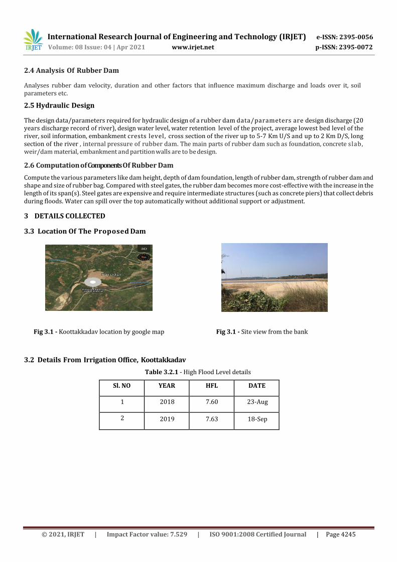
3.3 Location Of The Proposed Dam
Fig 3.1 - Koottakkadav location by google map Fig 3.1 - Site view from the bank
3.2 Details From Irrigation Office, Koottakkadav
Table 3.2.1 - High Flood Level details
Sl. NO YEAR HFL DATE
1 2018 7.60 23-Aug
2 2019 7.63 18-Sep
International Research Journal of Engineering and Technology (IRJET) e-ISSN: 2395-0056
Volume: 08 Issue: 04 | Apr 2021 www.irjet.net p-ISSN: 2395-0072
© 2021, IRJET | Impact Factor value: 7.529 | ISO 9001:2008 Certified Journal | Page 4246
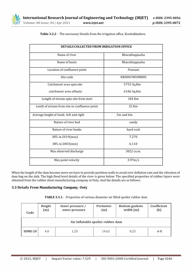
Table 3.2.2 - The necessary Details from the irrigation office, Koottakkadavu
When the length of the dam become more we have to provide partition walls to avoid over deflation rate and the vibration of dam bag on the slab. The high flood level details of the river is given below. The specified properties of rubber layers were obtained from the rubber sheet manufacturing company at Ooty. And the details are as follows.
3.3 Details From Manufacturing Company, Ooty
TABLE 3.3.1 - Properties of various diameter air filled spoiler rubber dam
DETAILS COLLECTED FROM IRRIGATION OFFICE
Name of river Bharathappuzha
Name of basin Bharathappuzha
Location of confluence point Ponnani
Site code KR000C9KUMBIDI
Catchment area upto site
catchment area of basin
5755 Sq.Km
6186 Sq.Km
Length of stream upto site from start 184 Km
Lenth of stream from site to confluence point 25 Km
Average height of bank: left and right 5m and 6m
Nature of river bed sandy
Nature of river banks hard rock
HFL in 2019(max)
HFL in 2003(min)
7.270
6.110
Max observed discharge 3022 cu.m.
Max point velocity 3.97m/s
Code
Height (m)
Inner pressure / outer pressure
Perimeter (m)
Bottom gaskets width (m)
Coefficient (k)
Air inflatable spoiler rubber dam
SDMS-20 4.0 1.25 14.62 8.25 6-8
International Research Journal of Engineering and Technology (IRJET) e-ISSN: 2395-0056
Volume: 08 Issue: 04 | Apr 2021 www.irjet.net p-ISSN:
2395-0072
© 2021, IRJET | Impact Factor value: 7.529 | ISO 9001:2008 Certified Journal | Page 4247
TABLE.3.3.2 - Properties of rubber layers
Item Unit Outer layer Middle layer, inner layer Cover rubber sheet
Tensile strength at break Mpa 14 12 6
Elongation at break % 400 400 250
Hardness 55-65 50-60 55-65
flexibility,no cracking 10000 times 20 20 20
Brittleness temperature °C -30 -30 -30
Wear loss Cu.cm/1.61Km 1.0 1.0 1.2
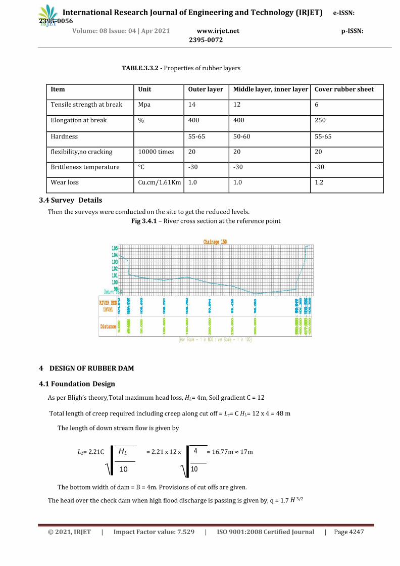
3.4 Survey Details
Then the surveys were conducted on the site to get the reduced levels.
Fig 3.4.1 – River cross section at the reference point
4 DESIGN OF RUBBER DAM
4.1 Foundation Design
As per Bligh’s theory,Total maximum head loss, HL= 4m, Soil gradient C = 12
Total length of creep required including creep along cut off = Lc= C HL= 12 x 4 = 48 m
The length of down stream flow is given by
L2= 2.21C = 2.21 x 12 x = 16.77m ≈ 17m
The bottom width of dam = B = 4m. Provisions of cut offs are given.
The head over the check dam when high flood discharge is passing is given by, q = 1.7 H 3/2
HL
10
4
10

International Research Journal of Engineering and Technology (IRJET) e-ISSN: 2395-0056
Volume: 08 Issue: 04 | Apr 2021 www.irjet.net p-ISSN:
2395-0072
© 2021, IRJET | Impact Factor value: 7.529 | ISO 9001:2008 Certified Journal | Page 4248
HLXq
10X75
Where q = Q/L = 3032/420 = 7.22 m3 . Then, 7.22 = 1.7 H 3/2 ⸫H =
3/2
7.1
22.7
= 2.62m
Head over the dam crest = 2.62m, ⸫u/s HFL (bed level=98.00 and crest level=102.00) = 98+4+2.62 = 104.62m.
Now R = Lacey’s regime scoured depth = 1.35
3/12
f
qAssuming f = 1, R = 1.35
3/12
1
22.7
= 5.04m
Depth of u/s sheet pile from below u/s HFL = 2R = 2 X 5.04= 10.08m. ⸫Level of bottom of u/s sheet pile = 10.08 - 7.63 = 2.45m Provide a depth of 2.5m for u/s cut off. Use a similar d/s cut off of 2.5m depth below the check dam floor. Now total creep length provided except u/s floor = (2 x 2.5) + bottom width of floor +L2+(2x2.5)= 5+4+5+17 = 31m.
The balance length , i.e. 48-31 = 17m
L+L =18C = 18 x 12x
2 3
4 X7.22
750
=42.38m, L3 = 42.38-17 = 25.38m ≈ 26m
Hence provide ( say 1m thick ) d/s loose talus of 26m in length.
The length of u/s talus
D/s Floor Thickness :
L4 may be kept as equal to 1/2 the length of d/s talus, i.e. 13m.
The H.G line is now plotted . The maximum Ordinate of the H.G. line above the bottom of the floor for the d/s portion at the junction of dam wall, h=(4/48)
x 18 =1.5m. The thickness of d/s floor at this point is then obtained by Eq.
t = 1.33 (1G
h) = 1.33 X (
165.2
5.1
) = 1.21m 1.3m.
4.2 Rubber Bag Design
Table below shows the appropriate measures of the rubber bag according to the environment conditions on there.
The length of the rubber bag = 30m
Diameter of the rubber bag = 4m (to protect the irrigation projects already exist in there )
Table 4.2.1- Spoiler air filled rubber bag details
Code Height (m) Innerpressure (N/sq.m) Perimeter (m) Coefficient (K)
SDMS-20 4.0 1.25 14.62 6-8
4.3 Abutment Design
Top bank level = 105.58 Good , soil level = 95.5 Provide top with of 0.5m, ⸫ Height of the abutment = 105.58-95.50 =10.08m, Bottom width of abutment = 0.4 x height = 0.4 x 10.08 = 4.032m
4.4 Design Of Wing Walls
Top level of wing wall= top level of abutment = upstream bank level= 105.58 Bottom level of wing wall= good soil foundation level= 95.00, top thickness of wing wall= top thickness of abutment = 0.5m Bottom thickness of wing wall = 0.4x height of wing wall =0.4x (top level- bottom level) =4.032m
Wing wall is splayed one to one and has enough length such that it gets keyed in to the bank (splay= horizontal slope).Use similar downstream wingwalls.

International Research Journal of Engineering and Technology (IRJET) e-ISSN: 2395-0056
Volume: 08 Issue: 04 | Apr 2021 www.irjet.net p-ISSN: 2395-0072
© 2021, IRJET | Impact Factor value: 7.529 | ISO 9001:2008 Certified Journal | Page 4249
4.5 Design of Anchorage System
We are using anchorage of dam bag with concrete base. Steel clamps are provided with high strength anchorage bolt for fixing the rubber bag on the dam. And from this two bolt system was using here.
And its parts are as below:
1) Plastic washers : Inner diameter: 21mm , Outer diameter: 42mm, Thickness: 2.8mm
2) Steel tube : Material: #45 steel, Inner diameter: 36mm Outer diameter: 50mm, Length: 210mm
3) Anchor bolt : Model: MSGLW-335/20X250, Material: MnSi
4) Bottom rigid cylinder : Diameter: 35mm, Height:50mm, Material: Steel
5) Nut : Thread specification: M20 Height: 16mm
6) Square pallet: Length: 50mm Width: 50mm, Thickness: 22mm
7) Resign anchoring agent : Model: MSM2360, Uniaxial compressive strength: 45.1 Mpa , Tensile strength: 3.12 Mpa
8) Concrete matrix : Ratio of water, ash and sand: 0.5:1:3 , Uniaxial compressive strength: 35.3 Mpa ,Tensile strength: 2.75 Mp
4.6 Automatic Air Control System
There will be an automatic air control system for the air filling and removing. Pumping system will be used for this.
Fig 4.6.1- Air Controlling systems of rubber bag
5. RESULTS AND DISCUSSION
By the construction of this rubber dam there can maximize irrigation and control the flood.
The site for this project is of good soil at the banks and sandy soil at the river bed from the bore logged details we found that the hard soil is at 2.5m depth and river bank is at 105.00RL.
By using rubber dam we can avoid mass construction and its time period for construction.
Table 5.1 - Foundation details Table 5.2 - Rubber bag details
Length of u/s concrete floor 17 m
Length of d/s concrete floor 17 m
Length of u/s stone aprons / talus 13 m
Length of d/s stone aprons / talus 26 m
Width of dam below rubber bag 4 m
Thickness of d/s floor at the junction 1.3 m
Diameter 4 m
Code SDMS 20
Inner pressure 1.25 N/sq.m
Perimeter 14.62 m
Length 3 m

International Research Journal of Engineering and Technology (IRJET) e-ISSN: 2395-0056
Volume: 08 Issue: 04 | Apr 2021 www.irjet.net p-ISSN: 2395-0072
Depth of brick foundation at the ends 0.5 m
Table 5.3- Abutment details Table 5.4 - Wing wall details
Top thickness 0.5 m
Height of abutment 10.08 m
Bottom width 4.032 m
Table 5.5 - Anchorage system details
Plastic washers Inner diameter – 21 mm, Outer diameter – 42 mm, Thickness– 2.8 mm
Steel tube Inner diameter – 36 mm, Outer diameter – 50 mm, Length– 210mm
Anchor bolt Model- MSGLW-335/20X250, Material- Mnsi
Bottom rigid cylinder Diameter– 35mm, Height– 50mm, Material– Steel
Nut Thread specification - M2, Height- 16mm
Square pallet Length- 50mm, Width - 50 mm, Thickness- 22mm
Resign anchoring agent Model- MSM2360, Uniaxial compressive strength - 45.1Mpa Tensile strength- 3.12 Mpa
Concrete matrix Ratio of water, ash and sand- 0.5:1:3 Uniaxial compressive strength - 35.3 Mpa, Tensile strength- 2.75 Mpa
6. CONCLUSION
As per our studies conducted at Koottakkadav we understood that there is a need for storage of water and to control flood. We identified that the check dam can minimize the problems. This can reduce the scarcity on there but the possibility of f load increases. If we choose a concrete dam the flood intensity increases. We found that the property of inflation and deflation mechanism of rubber dam can solve these two problems simultaneous. From the detailed survey a suitable location for this dam was found out. Then the soil characteristics, river characteristics and other details required for this design purpose are collected from irrigation office and rubber manufacturing company. Hydraulic design was thus completed with the help of information from reference. With these design values we drawn 2D and 3D drawings of the dam. After the designing we achieve the goals specified.
REFERENCES
[1] Yousef Parish, ‘’Assessment the stability of embankment dams during rapid depletion of reservoir’’, International journal of advance engineering and research development,19,275-288 (2016)
[2] H. Chanson,’’Hydraulics of rubber dam overflow’’, 23, 172-190 (2016)
[3] Yousuf Parish Evaluating the design, construction and use of Rubber dams,14,98-105, Canadian journal of civil engineering (2016)
[4] J Jena,’’Hydraulic Rubber Dam, Elsevier Bonding and Anchoring System f or Rubber Dam’’, volume 2, 65-68, German version EN ISO 283(2007), Beuth verlag GmbH (2019)
[5] Jamalodin Norzaie, Abdul Halim Ghazali, et al.(2018)Behavior of inflatable dams under hydrostatic conditions,8, 293-297, International journal of advance engineering and research development.
Top width 0.5 m
Bottom width 4.032 m
Height 10.58 m
© 2021, IRJET | Impact Factor value: 7.529 | ISO 9001:2008 Certified Journal | Page 4250