ru relays & sockets
TRANSCRIPT

Switc
hes
& P
ilot L
ight
sSi
gnal
ing
Ligh
tsRe
lays
& S
ocke
tsTi
mer
sCo
ntac
tors
Term
inal
Blo
cks
Circ
uit B
reak
ers
RU Relays & Sockets
790 www.IDEC.com
RU Series Universal Relays
Key features:• Full featured universal miniature relays• Designed with environment taken into consideration • Two terminal styles: plug-in and PCB mount• Non-polarized LED indicator• No internal wires, lead-free construction• Cadmium-free contacts• Mechanical flag indicator• Manual latching lever with color coding for AC or DC coil• Snap-on yellow marking plate; optional marking plates are available in four other colors• Maximum contact ratings: 10A (RU2), 6A (RU4), 3A (RU42)• UL Recognized, CSA Certified, EN Compliant
EN61810-1
With Latching or Momentary Lever
Mechanical Indicator*The contact position can be confirmed through the five small windows.
Marking PlateStandard yellow marking plate is easily replaced with optional marking plates in four colors for easy identification of relays.
LED Indicator*Non-polarized green LED indicator is standard provision for plug-in terminal, latching lever types
Latching and Momentary LeverUsing the lever, operation can be checked without energiz-ing the coil. The lever is color coded for AC and DC coils.
Latching Momentary
AC coil: Orange Red
DC coil: Green Blue
Note: Turn off the power to the relay coil when using the latching lever. After checking the operation, return the latching lever in the normal position.
In Normal Operation
Standard (without lever)
Coil Voltage Tape Color
24V AC White
100 to 110V AC Clear
110 to 120V AC Blue
200 to 220V AC Black
220 to 240V AC Red
24V DC Green
6V DC
Voltage marking on yellow tape
12V DC
48V DC
110V DC
AC/DC Color MarkingFor identification of AC or DC coils. AC coil: Yellow DC coil: Blue
Mechanical Indicator*
Marking Plate
LED Indicator*Non-polarized green LED indicator is standard provision for plug-in terminal types.
AC Coil DC Coil
*Not available on PCB type.

Switches &
Pilot LightsSignaling Lights
Relays & Sockets
Timers
ContactorsTerm
inal BlocksCircuit Breakers
791800-262-IDEC (4332) • USA & Canada
RURelays & Sockets
Part Number Selection
Part Number
Contact Model Standard With Latching Lever With Momentary Lever Coil Voltage Code(Standard Stock in bold)
DPDT (10A) Standard RU2S-C-0 RU2S-0 RU2S-M-0A24, A110, A220D6, D12, D24, D48, D110
With RC (AC coil only) RU2S-CR-0 RU2S-R-0 RU2S-MR-0 A110, A220
With diode (DC coil only) RU2S-CD-0 RU2S-D-0 RU2S-MD-0 D6, D12, D24, D48, D110
PCB RU2V-NF-0 — — A24, A110, A220D6, D12, D24, D48, D110
4PDT (6A) Standard RU4S-C-0 RU4S-0 RU4S-M-0A24, A110, A220D6, D12, D24, D48, D110
With RC (AC coil only) RU4S-CR-0 RU4S-R-0 RU4S-MR-0 A110, A220
With diode (DC coil only) RU4S-CD-0 RU4S-D-0 RU4S-MD-0 D6, D12, D24, D48, D110
PCB RU4V-NF-0 — — A24, A110, A220D6, D12, D24, D48, D110
4PDT Bifurcated (3A) Standard RU42S-C-0 RU42S-0 RU42S-M-0A24, A110, A220D6, D12, D24, D48, D110
With RC (AC coil only) RU42S-CR-0 RU42S-R-0 RU42S-MR-0 A110, A220
With diode (DC coil only) RU42S-CD-0 RU42S-D-0 RU42S-MD-0 D6, D12, D24, D48, D110
PCB RU42V-NF-0 — — A24, A110, A220D6, D12, D24, D48, D110
1. Plug-in terminal models have an LED indicator and a mechanical indicator as standard. 2. PCB models do not have an LED indicator or a mechanical indicator. Ordering Information
When ordering, specify the Part No. and coil voltage code:
(example) RU2S-C A110 Part No. Coil Voltage Code
Coil Voltage TableCoil Voltage Code A24 A110 A220 D6 D12 D24 D48 D110
Coil Rating 24V AC 110-120V AC 220-240V AC 6V DC 12V DC 24V DC 48V DC 110V DC
Sockets
Relays Spring Clamp DIN Rail Mount
Standard DIN Rail Mount
Finger-safe DIN Rail Mount Panel Mount PCB Mount
RU2S (DPDT) SU2S-11L SM2S-05 SM2S-05CSY4S-51
SM2S-61SM2S-62
RU4S (4PDT)RU42S (4PDT) SU4S-11L SY4S-05 SY4S-05C SY4S-61
SY4S-62

Switc
hes
& P
ilot L
ight
sSi
gnal
ing
Ligh
tsRe
lays
& S
ocke
tsTi
mer
sCo
ntac
tors
Term
inal
Blo
cks
Circ
uit B
reak
ers
RU Relays & Sockets
792 www.IDEC.com
Hold Down Springs & Clips
Appearance Item Relay For DIN Mount Socket
For Through Panel & PCB Mount Socket
Pullover Wire Spring
RU2S/RU4S/RU42S SY4S-02F1 SY4S-51F1
Note: Order 2 pieces for each relay
Leaf Spring (side latch)
RU2S/RU4S/RU42S SFA-202* SFA-302*
Leaf Spring (top latch)
RU2S/RU4S/RU42S SFA-101* SFA-301*
Accessories Name Part Number Color Code *
Marking Plate RU9Z-P* A (orange), G (green), S (blue), W (white), Y (yellow)
Specify a color code when ordering. The marking plate can be removed from the relay by inserting a flat screwdriver under the marking plate.
SpecificationsModel (Contact) RU2 (DPDT) RU4 (4PDT) RU42 (4PDT-bifurcated)
Contact Material Silver alloy Silver (gold clad) Silver-nickel (gold clad)
Contact Resistance 1 50 mΩ maximum
Minimum Applicable Load 2
24V DC, 5 mA(reference value) 1V DC, 1 mA 1V DC, 0.1 mA
Operating Time 3 20 ms maximum
Release Time 3 20 ms maximum
Power Consumption AC: 1.1 to 1.4VA (50 Hz), 0.9 to 1.2VA (60 Hz) DC: 0.9 to 1.0W
Insulation Resistance 100MΩ minimum (500V DC megger)
Dielectric Strength
Between contact and coil: 2500V AC, 1 minute
Between contacts of different poles:
2500V AC, 1 minute 2000V AC, 1 minute
Between contacts of the same pole: 1000V AC, 1 minute
Operating Frequency Electrical: 1800 operations/h maximumMechanical: 18,000 operations/h maximum
Vibration Resistance Damage limits: 10 to 55 Hz, amplitude 0.5 mmOperating extremes: 10 to 55 Hz, amplitude 0.5 mm
Shock Resistance Damage limits: 1000 m/s2 (100G)Operating extremes: 150 m/s2 (15G)
Mechanical Life AC: 50,000,000 operationsDC: 100,000,000 operations 50,000,000 operations
Electrical Life 4 See table on page 794
Operating Temperature 5
PCB model: –55 to +70°C (no freezing)Blade model: –55 to +60°C (no freezing)
Operating Humidity 5 to 85% RH (no condensation)
Weight Approx. 35g
1. Measured using 5V DC, 1A voltage drop method2. Measured at operating frequency of 120 operations/min (failure rate level P, reference value)3. Measured at the rated voltage (at 20°C), excluding contact bouncing; Release time of AC relays with RC: 25 ms maximum Release time of DC relays with diode: 40 ms maximum
4. Contact Load and Electrical Life (at ambient temperature 20°C)5. Measured at the rated voltage.

Switches &
Pilot LightsSignaling Lights
Relays & Sockets
Timers
ContactorsTerm
inal BlocksCircuit Breakers
793800-262-IDEC (4332) • USA & Canada
RURelays & Sockets
AccessoriesItem Appearance Use with Part No. Remarks
Aluminum DIN Rail (1 meter length)
All DIN rail sockets BNDN1000
The BNDN1000 is designed to accommodate DIN mount sockets. Made of durable extruded aluminum, the BNDN1000 measures 0.413 (10.5mm) in height and 1.37 (35mm) in width (DIN standard). Standard length is 39” (1,000mm).
DIN Rail End Stop DIN rail BNL5 9.1 mm wide.
Replacement Hold-Down Spring Anchor
Horseshoe clip for DIN rail sockets Y778-011 For use on DIN rail mount socket when using pullover wire hold down
spring. 2 pieces included with each socket.
Coil Ratings
Rated Voltage (V)Coil
Voltage Code
Rated Current (mA) ±15% (at 20°C) Coil Resistance (Ω)
±10% (at 20°C)
Operating Characteristics (values at 20°C)
50 Hz 60 Hz Maximum Continuous Applied Voltage Pickup Voltage Dropout Voltage
AC (50/60 Hz)
24 A24 49.3 42.5 164
110% 80% maximum 30% minimum110-120 A110 8.4-10.0 7.1-8.2 4,550
220-240 A220 4.2-5.0 3.6-4.2 18,230
DC
6 D6 155 40
110% 80% maximum 10% minimum
12 D12 80 160
24 D24 44.7 605
48 D48 18 2,560
110 D110 8.9 12,100
1. The rated current includes the current of the LED indicator.
Surge Suppressor RatingsModel Ratings
AC Coil With RC RC series circuitR: 20 kΩ, C: 0.033 µF
DC Coil With Diode Diode reverse voltage: 1000VDiode forward current: 1A
Contact RatingsMaximum Contact Capacity
Contact Continuous Current
Allowable Contact Power Voltage (V)
Rated Load
Resistive Load Inductive Load Res. Load Ind. Load
DPDT 10A2500VA AC 1250VA AC 250 AC 10A 5A
300W DC 150W DC 30 DC 10A 5A
4PDT 6A1500VA AC 600VA AC 250 AC 6A 0.8A
180W DC 90W DC 30 DC 6A 1.5A
4PDTbifurcated 3A
750VA AC 200VA AC 250 AC 3A 0.8A
90W DC 45W DC 30 DC 3A 1.5A
1. On 4PDT relays, the maximum allowable total current of neighboring two poles is 6A. At the rated load, make sure that the total current of neighboring two poles does not exceed 6A (3A + 3A = 6A).
2. Inductive load for the rated load — cos ø = 0.3, L/R = 7 ms
UL and c-UL Ratings
VoltageResistive General Use Horse Power Rating
RU2 RU4 RU42 RU2 RU4 RU42 RU2 RU4 RU42
250V AC 10A — 3A — 6A — — 1/10HP —
30V DC 10A 6A 3A — — — — — —
CSA Ratings
VoltageResistive
RU42
250V AC 3A
30V DC 3A
TÜV Ratings
VoltageResistive Inductive
RU2 RU4 RU42 RU2 RU4 RU42
250V AC 10A 6A 3A 5A 0.8A 0.8A
30V DC 10A 6A 3A 5A 1.5A 1.5A

Switc
hes
& P
ilot L
ight
sSi
gnal
ing
Ligh
tsRe
lays
& S
ocke
tsTi
mer
sCo
ntac
tors
Term
inal
Blo
cks
Circ
uit B
reak
ers
RU Relays & Sockets
794 www.IDEC.com
Socket SpecificationsSockets Terminal Electrical Rating Wire Size Torque
DIN Rail Mount Sockets
SU2S-11L Spring clamp terminals 250V/10A 24-16 AWG —
SU4S-11L Spring clamp terminals 250V/6A (using RU4), 10A (using RU2) 24-16 AWG —
SM2S-05 M3 screw with captive wire clamp 300V, 10A Maximum up to 2–#14AWG 5.5-9in•lbs
SM2S-05C M3 screw with captive wire clamp, fingersafe 300V, 10A Maximum up to 2–#14AWG 5.5-9in•lbs
SY4S-05 M3 screw with captive wire clamp 300V, 7A (using RU4), 10A (using RU2) Maximum up to 2–#14AWG 5.5-9in•lbs
SY4S-05C M3 screw with captive wire clamp, fingersafe 300V, 7A (using RU4), 10A (using RU2) Maximum up to 2–#14AWG 5.5-9in•lbs
Through Panel Mount Socket SY4S-51 Solder 300V, 7A — —
PCB Mount SocketSY4S-61 PCB mount 300V, 7A — —
SY4S-62 PCB mount 250V, 7A — —
Electrical Life Curves
RU2 (Resistive Load) RU4 (Resistive Load) RU42 (Resistive Load)
10
1000
100
1 10 5 10.50.1
110V DC 30V DC 250V AC
Load Current (A)
(¥ 1
0,00
0 op
erat
ions
)
6 3 10.50.1
10
1000
100
1
110V DC 30V DC 250V AC
Load Current (A)
(¥ 1
0,00
0 op
erat
ions
)
10
100
10.02 6310.50.1
110V DC 30V DC 250V AC
Load Current (A)
(¥ 1
0,00
0 op
erat
ions
)RU2 (Inductive Load) RU4 (Inductive Load) RU42 (Inductive Load)
0.1 0.5 1 5 101
100
1000
10
110V DC250V AC/30V DC
Load Current (A)
(¥ 1
0,00
0 op
erat
ions
)
DC: L/R = 7 msAC: cos ø = 0.3
1
100
10
0.1 0.50.02Load Current (A)
(¥ 1
0,00
0 op
erat
ions
)
DC: L/R = 7 msAC: cos ø = 0.3
110V DC 30V DC 250V AC
1
100
10
0.1 0.50.02Load Current (A)
(¥ 1
0,00
0 op
erat
ions
)
DC: L/R = 7 msAC: cos ø = 0.3
110V DC 30V DC 250V AC
Maximum Switching Current
RU2 RU4 RU42 (Bifurcated)
10
5
0.1
1
10 30 100 250 500
AC resistiveAC inductive(cos ø = 0.3)
Load Voltage (V)
Load
Cur
rent
(A) DC resistive
DC inductiveL/R = 7 ms

Switches &
Pilot LightsSignaling Lights
Relays & Sockets
Timers
ContactorsTerm
inal BlocksCircuit Breakers
795800-262-IDEC (4332) • USA & Canada
RURelays & Sockets
Ambient Temperature vs. Temperature Rise Curves
RU2 (AC Coil, 50 Hz) RU2 (AC Coil, 60 Hz) RU2 (DC Coil)120
110
100
90
80
70
60
50
40
30
20
10
706050403020100Ambient Temperature (C)
Tem
pera
ture
Ris
e (C
)
Load current 5A ¥ 2 poles
Load current 10A ¥ 2 poles
No load current
0 10 20 30 40 50 60 70
10
20
30
40
50
60
70
80
90
100
110
120
Ambient Temperature (C)Te
mpe
ratu
re R
ise
(C)
Load current 5A ¥ 2 poles
Load current 10A ¥ 2 poles
No load current
0 10 20 30 40 50 60 70
10
20
30
40
50
60
70
80
90
100
110
120
Ambient Temperature (C)
Tem
pera
ture
Ris
e (C
)
Load current 5A ¥ 2 poles
Load current 10A ¥ 2 poles
No load current
RU4/RU42 (AC Coil, 50 Hz) RU4/RU42 (AC Coil, 60 Hz) RU4/RU42 (DC Coil)
0 10 20 30 40 50 60 70
10
20
30
40
50
60
70
80
90
100
110
120
Ambient Temperature (C)
Tem
pera
ture
Ris
e (C
)
Load current 3A ¥ 4 poles
Load current 6A ¥ 2 poles
No load current
120
110
100
90
80
70
60
50
40
30
20
10
706050403020100Ambient Temperature (C)
Tem
pera
ture
Ris
e (C
)
Load current 3A ¥ 4 poles
Load current 6A ¥ 2 poles
No load current
120
110
100
90
80
70
60
50
40
30
20
10
706050403020100Ambient Temperature (C)
Tem
pera
ture
Ris
e (C
)
Load current 3A ¥ 4 poles
Load current 6A ¥ 2 poles
No load current
The above temperature rise curves show the characteristics when 100% the rated coil voltage is applied. The heat resistance of the coil is 120°C. The slant dashed line indicates the allowable temperature rise for the coil at different ambient temperatures.Load current 6A x 2 poles is for the RU4 models only.

Switc
hes
& P
ilot L
ight
sSi
gnal
ing
Ligh
tsRe
lays
& S
ocke
tsTi
mer
sCo
ntac
tors
Term
inal
Blo
cks
Circ
uit B
reak
ers
RU Relays & Sockets
796 www.IDEC.com
Internal Connection (View from Bottom)RU2S-* Standard RU2S-*R with RC RU2S-*D With Diode RU2V-NF-*
(14)A2(13)A1
(12)41(9)11
(8)44(5)14
(4)42(1)12
Over 24V AC/DC coil
24V AC/DC coil or less
(13)A1 (14)A2
(1)12 (4)42
(5)14 (8)44
(9)11 (12)41
(1)12 (4)42
(5)14 (8)44
(9)11 (12)41
(13)A1 (14)A2
Over 24V DC coil
24V DC coil or less
(14)A2(13)A1
(12)41(9)11
(8)44(5)14
(4)42(1)12
RU4S-*/RU42S-* Standard RU4S-*R/RU42S-*R With RC RU4S-*D/RU42S-*D With Diode RU4V-NF-*/RU42V-NF-*
(1)12 (2)22 (3)32 (4)42
(5)14 (6)24 (7)34 (8)44
(9)11 (10)21 (11)31 (12)41
(13)A1 (14)A2
Over 24V AC/DC coil
(14)A2(13)A1
(12)41(11)31(10)21(9)11
(8)44(7)34(6)24(5)14
(4)42(3)32(2)22(1)12
24V AC/DC coil or less
(14)A2(13)A1
(12)41(11)31(10)21(9)11
(8)44(7)34(6)24(5)14
(4)42(3)32(2)22(1)12
Over 24V DC coil
(14)A2(13)A1
(12)41(11)31(10)21(9)11
(8)44(7)34(6)24(5)14
(4)42(3)32(2)22(1)12
24V DC coil or less
(14)A2
(1)12 (2)22 (3)32 (4)42
(5)14 (6)24 (7)34 (8)44
(9)11 (10)21 (11)31 (12)41
(13)A1 (14)A2(13)A1
(12)41(11)31(10)21(9)11
(8)44(7)34(6)24(5)14
(4)42(3)32(2)22(1)12
Dimensions (mm)
RU2S RU2V
Latching LeverAC: OrangeDC: Green
Marking Plate (yellow)
ø1.2 ¥ 2.2 Hole
LED Indicator (green)
35.0
6.4 2.60.5
27.5
21.0
14
58
912
1314
Marking Plate Removal Slot
Mechanical Indicator Window
8-ø1 Holes
27.5
12.74.16.4
7.0
13.2
0.8
13.2
2.64.0
0.5
21.0
0.5
35.0
Mounting Hole Layout
Marking Plate (yellow)
Marking Plate Removal Slot
Color MarkingAC: YellowDC: Blue
All dimensions in mm.
Marking plate removal slot is provided only on one side. Insert a flat screwdriver into the slot to remove the marking
plate.
Switches &
Pilot LightsSignaling Lights
Relays & Sockets
Timers
ContactorsTerm
inal BlocksCircuit Breakers
797800-262-IDEC (4332) • USA & Canada
RURelays & Sockets
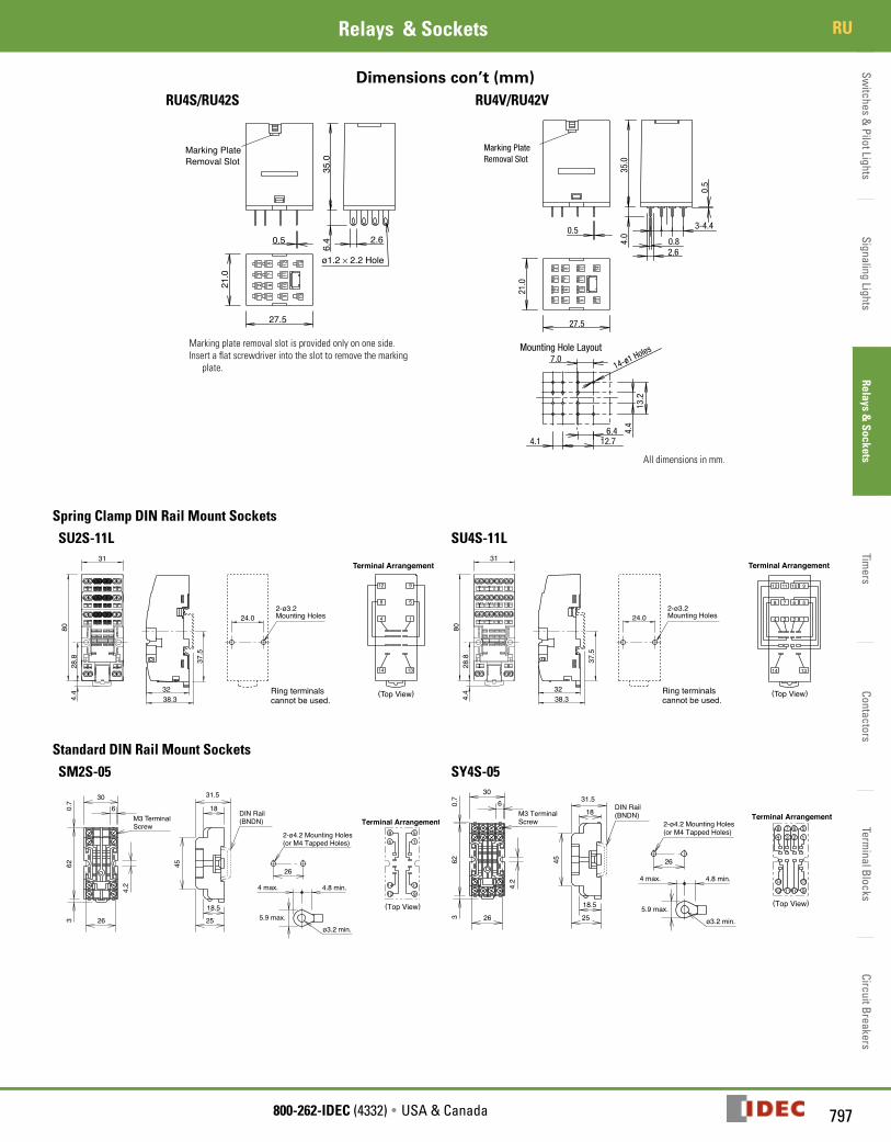
Dimensions con’t (mm)RU4S/RU42S RU4V/RU42V
1413
1211
109
87
65
43
21
6.4
21.0
27.5
0.5 2.6
35.0
Latching LeverAC: OrangeDC: Green
ø1.2 × 2.2 Hole
LED Indicator (green)
Marking Plate Removal Slot
Mechanical Indicator WindowMarking Plate (yellow)
3-4.4
0.82.6
4.0
0.5
0.5
27.5
21.0
13.2
7.0
6.44.1 12.7
4.4
35.0
14-ø1 HolesMounting Hole Layout
Marking Plate (yellow)
Marking Plate Removal Slot
Color MarkingAC: YellowDC: Blue
All dimensions in mm.
Marking plate removal slot is provided only on one side. Insert a flat screwdriver into the slot to remove the marking
plate.
Spring Clamp DIN Rail Mount Sockets
SU2S-11L SU4S-11L
14 13
14
8 5
912
Terminal Arrangement
38.3
37.5
32
2-ø3.2 Mounting Holes24.0
28.8
4.4
31
80
Ring terminals cannot be used.
(Top View)
12 11 10 9
5678
4 3 2 1
1314
Terminal Arrangement
38.3
37.5
32
2-ø3.2 Mounting Holes24.0
28.8
4.4
31
80
(Top View)Ring terminals cannot be used.
Standard DIN Rail Mount Sockets
SM2S-05 SY4S-05
630
26
4.2
623
0.7
M3 TerminalScrew
18.5
25
45
18
31.5
DIN Rail(BNDN)
14
139
1412
58
Terminal Arrangement
26
2-ø4.2 Mounting Holes(or M4 Tapped Holes)
5.9 max.
4 max. 4.8 min.
ø3.2 min.
(Top View)
630
26
4.2
623
0.7
M3 TerminalScrew
18.5
25
45
18
31.5DIN Rail(BNDN)
1
139
1412 11 10
56784 3 2
Terminal Arrangement
26
2-ø4.2 Mounting Holes(or M4 Tapped Holes)
5.9 max.
4 max. 4.8 min.
ø3.2 min.
(Top View)

Switc
hes
& P
ilot L
ight
sSi
gnal
ing
Ligh
tsRe
lays
& S
ocke
tsTi
mer
sCo
ntac
tors
Term
inal
Blo
cks
Circ
uit B
reak
ers
RU Relays & Sockets
798 www.IDEC.com
Dimensions con’t (mm)
Finger-safe DIN Rail Mount Sockets
SM2S-05C SY4S-05C
ø5.5
25
18
2
306
64
26
46
1.6
4.2
29
18.2
M3 TerminalScrew
14
13
9
14
12
58
Terminal Arrangement
35.5
26
2-ø4.2 Mounting Holes(or M4 Tapped Holes)
DIN Rail(BNDN)
Ring terminals cannot be used. (Top View)
ø5.5 18
25
2
306
64
26
46
1.6
4.2
29
18.2
26
M3 TerminalScrew
1
13
9
14
12 11 10
5678
4 3 2
Terminal Arrangement
35.5
2-ø4.2 Mounting Holes(or M4 Tapped Holes)
DIN Rail(BNDN)
(Top View)Ring terminals cannot be used.
PCB Mount Sockets
SM2S-61 SM2S-62
3
11
15
27
31
0.3
25.4
21.2
1.5
13 14
159 12
84
Terminal Arrangement
* 19.2 min. when using hold-down springs
13.2 13.8 min.
9
9-ø2 holes
(Tolerance 0.1)
14.2
min
.*
16.8
4.1
10.4
1.4
(Bottom View)
(Tolerance 0.1)
13 14
159 12
84
Terminal Arrangement
1.5
13.2 8.2 min.**
3
11
15
21.2
29 0.3
9
9-ø2 holes
4.1
10.4
16.8
1.4
12.2
min
.*
17.2 min. when using a hold-down spring.13.2 min. when using a hold-down spring for
the relay with check button.
*
**
(Bottom View)
SY4S-61 SY4S-62
27
31
21.2
3
11
15
0.3
25.4
1.5
107
13 14
159
3
1284
62
11
Terminal Arrangement
* 19.2 min. when using hold-down springs
(Bottom View)
4.4
13.8 min.
9
15-ø2 holes
(Tolerance 0.1)
14.2
min
.*
16.8
4.110
.4
8.8
13.2
1.4
1.5
3
11
15
21.2
29 0.3
4.1
10.4
16.8
1.4
12.2
min
.*(Tolerance 0.1)
13.2 8.2 min.**
4.48.8
15-ø2 holes
9
107
13 14
159
3
1284
62
11
Terminal Arrangement
13.2 min. when using a hold-down spring for
the relay with check button
17.2 min. when using a hold-down spring.*
* *
(Bottom View)
Through Panel Mount Socket
SY4S-51
27
31
2.4
21.2
3
11
18.7
25.4
Panel Thickness:1 to 2
107
13 14
159
3
1284
62
11
Terminal Arrangement
25.6
0+0.5
+0.
20
* 10.4 min. when using hold-down springs
[27 (N–1) + 21.4]
5.4
min
.*
N: No. of sockets mounted0.3
(Bottom View)

Switches &
Pilot LightsSignaling Lights
Relays & Sockets
Timers
ContactorsTerm
inal BlocksCircuit Breakers
817800-262-IDEC (4332) • USA & Canada
Operating InstructionsRelays & Sockets
Operating Instructions
Driving Circuit for Relays
1. To ensure correct relay operation, apply rated voltage to the relay coil.
2. Input voltage for the DC coil: A complete DC voltage is best for the coil power to make sure of stable relay operation. When using a power supply containing a ripple voltage, suppress the ripple factor within 5%. When power is supplied through a rectification circuit, the relay operating characteristics, such as pickup voltage and dropout voltage, depend on the ripple factor. Connect a smoothing capacitor for better operating characteristics as shown below.
+– R
SmoothingCapacitor
Relay
Pulsation
Emin Emax Emean DC
Ripple Factor (%) ¥ 100%Emax – Emin
Emax = Maximum of pulsating currentEmin = Minimum of pulsating currentEmean = DC mean value
Emean
3. Leakage current while relay is off: When driving an element at the same time as the relay operation, special consideration is needed for the circuit design. As shown in the incorrect circuit below, leakage current (Io) flows through the relay coil while the relay is off. Leakage current causes coil release failure or adversely affects the vibration resistance and shock resistance. Design a circuit as shown in the correct example.
Incorrect Correct R
Io
TE
R
4. Surge suppression for transistor driving circuits: When the relay coil is turned off, a high-voltage pulse is generated, causing a transistor to deteriorate and sometimes to break. Be sure to connect a diode to suppress the back electromotive force. Then, the coil release time becomes slightly longer. To shorten the coil release time, connect a Zener diode between the collector and emitter of the transistor. Select a Zener diode with a Zener voltage slightly higher than the power voltage.
R
Back emfsuppressing diode
Relay+
–
Protection for Relay Contacts
1. The contact ratings show maximum values. Make sure that these values are not exceeded. When an inrush current flows through the load, the contact may become welded. If this is the case, connect a contact protection circuit, such as a current limiting resistor.
2. Contact protection circuit: When switching an inductive load, arcing causes carbides to form on the contacts, resulting in increased contact resistance. In consideration of contact reliability, contact life, and noise suppression, use of a surge absorbing circuit is recommended. Note that the release time of the load becomes slightly longer. Check the operation using the actual load. Incorrect use of a contact protection circuit will adversely affect switching characteristics. Four typical examples of contact protection circuits are shown in the following table:
RC
PowerC R Ind. Load
This protection circuit can be used when the load impedance is smaller than the RC impedance in an AC load power circuit.•R: Resistor of approximately the same resistance
value as the load•C:0.1 to 1 µF
This protection circuit can be used for both AC and DC load power circuits.R: Resistor of approximately the same resistance value as the loadC: 0.1 to 1 µF
Diod
e +
–
DPower Ind. Load
This protection circuit can be used for DC load power circuits. Use a diode with the following ratings.Reverse withstand voltage: Power voltage of the load circuit x 10Forward current: More than the load current
Varis
tor
Varis
tor
Power Ind. Load
This protection circuit can be used for both AC and DC load power circuits.For a best result, when using a power voltage of 24 to 48V AC/DC, connect a varistor across the load. When using a power voltage of 100 to 240V AC/DC, connect a varistor across the contacts.
3. Do not use a contact protection circuit as shown below:
Power
CLoad
This protection circuit is very effective in arc suppression when opening the contacts. But, the capacitor is charged while the contacts are opened. When the contacts are closed, the capacitor is discharged through the contacts, increasing the possibility of contact welding.
C LoadPower
This protection circuit is very effective in arc suppression when opening the contacts. But, when the contacts are closed, a current flows to charge the capacitor, causing contact welding.
Generally, switching a DC inductive load is more difficult than switching a DC resistive load. Using an appropriate arc suppressor, however, will improve the switching characteristics of a DC inductive load.
Soldering
1. When soldering the relay terminals, use a soldering iron of 30 to 60W, and quickly complete soldering (within approximately 3 seconds).
2. Use a non-corrosive rosin flux.
Operating Instructions

Switc
hes
& P
ilot L
ight
sSi
gnal
ing
Ligh
tsRe
lays
& S
ocke
tsTi
mer
sCo
ntac
tors
Term
inal
Blo
cks
Circ
uit B
reak
ers
Operating Instructions Relays & Sockets
818 www.IDEC.com
Operating Instructions con’t
Other Precautions
1. General notice: To maintain the initial characteristics, do not drop or shock the relay.
The relay cover cannot be removed from the base during normal operation. To maintain the initial characteristics, do not remove the relay cover.
Use the relay in environments free from condensation, dust, sulfur dioxide (SO2), and hydrogen sulfide (H2S).
Make sure that the coil voltage does not exceed applicable coil voltage range.
2. UL and CSA ratings may differ from product rated values determined by IDEC.
3. Do not use relays in the vicinity of strong magnetic field, as this may affect relay operation.
Safety Precautions• Turn off the power to the relay before starting installation, removal, wiring,
maintenance, and inspection of the relays. Failure to turn power off may cause electrical shock or fire hazard.
• Observe specifications and rated values, otherwise electrical shock or fire hazard may be caused.
• Use wires of the proper size to meet voltage and current requirements. Tight-en the terminal screws on the relay socket to the proper tightening torque.
• Surge absorbing elements on AC relays with RC or DC relays with diode are provided to absorb the back electromotive force generated by the coil. When the relay is subject to an excessive external surge voltage, the surge absorb-ing element may be damaged. Add another surge absorbing provision to the relay to prevent damage.
Precautions for the RU Relays
• Before operating the latching lever of the RU relay, turn off the power to the RU relay. After checking the circuit, return the latching lever to the origi-nal position.
• Do not use the latching lever as a switch. The durability of the latching lever is a minimum of 100 operations.
• When using DC loads on 4PDT relays, apply a positive voltage to terminals of neighboring poles and a negative voltage to the other terminals of neighbor-ing poles to prevent the possibility of short circuits.
• DC relays with a diode have a polarity in the coil terminals. Apply the DC volt-age to the correct terminals.