rtf rtf - hapo - trade modellbau
TRANSCRIPT

®
RTFRTF
© 2010 Horizon Hobby, Inc. 4105 Fieldstone Road Champaign, IL 61822
USA
Horizon Hobby UK Units 1-4 Ployters Rd
Staple Tye Harlow, Essex
CM18 7NS United Kingdom
Horizon Hobby Deutschland GmbH Hamburger Strasse 10
25335 Elmshorn Germany
E-flite® products are distributed exclusively by Horizon Hobby, Inc.
US Patent 7,391,320. Other Patents Pending
DSM and DSM2 are trademarks or registered trademarks of Horizon Hobby, Inc. The Spektrum trademark is used with permission of Bachmann Industries, Inc.
Spektrum radios and accessories are exclusively available from Horizon Hobby, Inc.
Printed 11/09 www.E-fliteRC.com 16165
Specifications
Length . . . . . . . . . . . . . . . . . . . . . 19.10 in (485mm)Height . . . . . . . . . . . . . . . . . . . . . 6.90 in (176mm)Main Rotor Diameter . . . . . . . . . . . 21.80 in (552mm)Tail Rotor Diameter . . . . . . . . . . . . 3.20 in (82mm)Weight with Battery . . . . . . . . . . . . 120 oz (340 g)Main Motor . . . . . . . . . . . . . . . . . . Brushless 3900Kv (installed)Tail Motor . . . . . . . . . . . . . . . . . . . Direct-Drive N60 (installed)Battery . . . . . . . . . . . . . . . . . . . . . 3S 11.1V 1000mAh Li-Po (included)Charger . . . . . . . . . . . . . . . . . . . . 3-Cell 11.1V Li-PoPower Supply . . . . . . . . . . . . . . . . AC to 12V DC, 1.5A (included)Transmitter . . . . . . . . . . . . . . . . . . HP6DSM 2.4GHz DSM 6-channel (included)*Receiver . . . . . . . . . . . . . . . . . . . . Spektrum AR6110e 2.4GHz DSM Microlite (installed)On-Board Electronics . . . . . . . . . . . 2-in-1 Mixer/ESCs (installed)Servos . . . . . . . . . . . . . . . . . . . . . DS75 Digital Sub-Micro (3 installed)Gyro . . . . . . . . . . . . . . . . . . . . . . . G110 Micro Heading Lock (installed)
* CCPM Helicopter programming is specific to Blade SR. Please do not attempt to use transmitter with any other CCPM helicopter

2 3
IntroductionYour Blade® SR is the absolute best way to transition from flying a coaxial heli to a single-rotor CCPM machine with confidence and, most importantly, success. It comes out of the box programmed to provide softer climb, pitch and roll response around the center of stick movement. This, combined with the tough, two-piece main frame and lower head speed, makes the Blade SR more forgiving and easier to master than most conventional CP helis. Plus, it’s big enough to fly outdoors even if there’s a little wind.
But before you take that first flight, read through this manual thoroughly. It includes vital information on safely charging the battery, proper pre-flight control checks and adjustments, and many other tips that will help make your first flight a successful one.
WarningAn RC helicopter is not a toy! If misused, it can cause serious bodily harm and damage to property. Fly only in open areas, preferably at AMA (Academy of Model Aeronautics) approved flying sites, following all instructions.
Keep items that can get entangled in the rotor blades away from the main and tail blades, including loose clothing, pencils and screwdrivers. Especially keep your hands away from the rotor blades.
Note on Lithium Polymer BatteriesLithium Polymer batteries are significantly more volatile than alkaline or Ni-Cd/Ni-MH batteries used in RC applications. All manufacturer’s instructions and warnings must be followed closely. Mishandling of Li-Po batteries can result in fire. Always follow the manufacturer’s instructions when disposing of Lithium Polymer batteries.
Using the ManualThis manual is divided into sections to help make final assembly and flight preparation easier to understand and to provide breaks between each major section. Remember to take your time and follow all directions.
Safety Precautions and WarningsAs the user of this product, you are solely responsible for operating it in a manner that does not endanger yourself and others or result in damage to the product or the property of others.
This model is controlled by a radio signal that is subject to interference from many sources outside your control. This interference can cause momentary loss of control so it is advisable to always keep a safe distance in all directions around your model, as this margin will help to avoid collisions or injury.
• Neveroperateyourmodelwithlowtransmitterbatteries.
• Alwaysoperateyourmodelinanopenareaawayfromcars,traffic,orpeople.
• Avoidoperatingyourmodelinthestreetwhereinjuryordamagecanoccur.
• Neveroperatethemodeloutintothestreetorpopulatedareasforanyreason.
• Carefullyfollowthedirectionsandwarningsforthisandanyoptionalsupportequipment(chargers,rechargeable battery packs, etc.) that you use.
• Keepallchemicals,smallpartsandanythingelectricaloutofthereachofchildren.
• Moisturecausesdamagetoelectronics.Avoidwaterexposuretoallequipmentnotspecificallydesignedandprotected for this purpose.
• Neverlickorplaceanyportionofyourmodelinyourmouthasitcouldcauseseriousinjuryorevendeath.
Table of Contents
Specifications ...................................................................................................................................1Introduction .......................................................................................................................................3Warning ............................................................................................................................................3Note on Lithium Polymer Batteries ......................................................................................................3Using the Manual ...............................................................................................................................3Safety Precautions and Warnings ........................................................................................................3Blade SR RTF Contents ......................................................................................................................4Needed to Complete .........................................................................................................................4Preparing for the First Flight ...............................................................................................................5Flying Checklist .................................................................................................................................5Battery Warnings and Guidelines .........................................................................................................6Battery Charging ...............................................................................................................................8Charge Errors and Indications ..........................................................................................................10Installing the Transmitter Batteries ....................................................................................................10Installing the Flight Battery ...............................................................................................................11Center of Gravity .............................................................................................................................12Transmitter Control Identification ......................................................................................................13Control Test ....................................................................................................................................142-in-1 Control Unit Description, Arming and Motor Control Test ...........................................................25Gyro Initialization, Response Test and Adjustment ..............................................................................27Initialization and Response Test ........................................................................................................28Gain Adjustments ............................................................................................................................29Trim Adjustments ............................................................................................................................30Servo Mode Setting .........................................................................................................................30Installing the Optional Training Gear ..................................................................................................31Understanding the Primary Flight Controls .........................................................................................34Dual Rates .....................................................................................................................................42Normal and Stunt Flight Modes .......................................................................................................44Throttle Hold ..................................................................................................................................47Before the First Flight .....................................................................................................................49Choosing a Flying Area ....................................................................................................................49Flying the Blade SR .........................................................................................................................50Tail Rotor Proportional Mix Trimmer Pot Adjustment ..........................................................................52Main Rotor Blade Tracking Adjustment ..............................................................................................53Flybar Paddle Tracking Adjustment ...................................................................................................55Flybar Weights, Head Dampening Shims and Fine-Tuning Cyclic Response ...........................................56Channel 5 Knob ...............................................................................................................................58Transmitter, Receiver Binding and Fail-Safe .......................................................................................59Transmitter and Receiver Range Testing ............................................................................................612009 Official AMA Safety Code ........................................................................................................62Replacement Parts List ....................................................................................................................64Optional Parts List ...........................................................................................................................65Exploded View Parts Listing .............................................................................................................68Exploded View .................................................................................................................................69Warranty Information .......................................................................................................................70Compliance Information for the European Union .................................................................................73

4 5
Blade SR RTF ContentsItem DescriptionNot Available Separately . . . . . . . . . . . . . . Blade SR RTF Airframe
EFLH1057 . . . . . . . . . . . . . . . . . . . . . . . . HP6DSM 6-Channel Transmitter, 2.4GHz DSM2: BSR
EFLB0997 . . . . . . . . . . . . . . . . . . . . . . . . 1000mAh 3S 11.1V 15C Li-Po, 20AWG JST/Balance
EFLC3105 . . . . . . . . . . . . . . . . . . . . . . . . 3S 11.1V Li-Po Balancing Charger, 0.8A
EFLC4000 . . . . . . . . . . . . . . . . . . . . . . . . AC to 12V DC, 1.5- Amp Power Supply
EFLH1519 . . . . . . . . . . . . . . . . . . . . . . . . Micro Helicopter Main Blade Holder: BSR
EFLH1129 . . . . . . . . . . . . . . . . . . . . . . . . Mounting Accessories & Wrench
EFLH1528 . . . . . . . . . . . . . . . . . . . . . . . . Hook and Loop Material
EFLH1444 . . . . . . . . . . . . . . . . . . . . . . . . Hook and Loop Strap
FUG4 . . . . . . . . . . . . . . . . . . . . . . . . . . . . 4 AA Batteries
Needed to CompleteNoadditionalequipmentisrequiredtocompleteyourBladeSR.
Preparing for the First FlightPlease note this checklist is not intended to be a replacement for the content of this instruction manual. Although it can beusedasaquickstartguide,westronglysuggestreadingthroughthismanualcompletelybeforeproceeding.
• Removeandinspectcontents
• Beginchargingtheflightbattery(seechargingproceduresonfollowingpages)
• Installthe4includedAAbatteriesinthetransmitter
• Installtheflightbatteryinthehelicopter(onceithasbeenfullycharged)
• ChecktheCenterofGravityofthehelicopter(seepage12)
• Testthecontrols(seepage14)
• InstalltheoptionalTrainingGearSet(EFLH1527;stronglyrecommendedifthisisyourfirstcollective-pitchequippedhelicoptermodel)
• Familiarizeyourselfwiththecontrols
• Findasuitableareaforflying
Flying ChecklistPlease note this checklist is not intended to be a replacement for the content of this instruction manual. Although it can beusedasaquickstartguide,westronglysuggestreadingthroughthismanualcompletelybeforeproceeding.
q Always turn the transmitter on first
q Plug the flight battery into the 2-in-1 control unit
q Allow the 2-in-1 control unit and gyro to arm and initialize properly
q Fly the model
q Land the model
q Unplug the flight battery from the 2-in-1 control unit
q Always turn the transmitter off last
6 7
Battery Warnings and GuidelinesThe 3S 11.1V 1000mAh Lithium Polymer Battery Pack (EFLB0997) included with your Blade SR features Charge Protection Circuitry and Balance Charging via the included 3S 11.1V Lithium Polymer Balancing Charger (EFLC3105). However, to help ensure a safe charge every time, you MUST read the following safety instructions and warnings before handling, charging or using the Li-Po battery pack.
Note: Lithium Polymer batteries are significantly more volatile than the alkaline, Ni-Cd or Ni-MH batteries used in RC applications. All instructions and warnings must be followed exactly. Mishandling of Li-Po batteries can result in fire.
By handling, charging or using the included Li-Po battery you assume all risks associated with lithium batteries. If you do not agree with these conditions, return your complete Blade SR model in new, unused condition to the place of purchase immediately.
• Youmustchargetheincluded3S11.1V1000mAhLi-Pobatterypackinasafeareaawayfromflammablematerials.
• Donotchargethebatterywheninstalledinthehelicopter.
• Neverchargethebatteryunattended.Whenchargingthebatteryyoushouldmonitorthechargingprocessand react to potential problems that may occur.
• Afterflight,thebatterymustbecooledtoambienttemperaturebeforecharging.
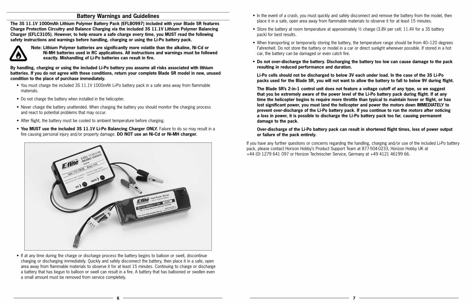
•You MUST use the included 3S 11.1V Li-Po Balancing Charger ONLY. Failure to do so may result in a fire causing personal injury and/or property damage. DO NOT use an Ni-Cd or Ni-MH charger.
• Ifatanytimeduringthechargeordischargeprocessthebatterybeginstoballoonorswell,discontinuecharging or discharging immediately. Quickly and safely disconnect the battery, then place it in a safe, open area away from flammable materials to observe it for at least 15 minutes. Continuing to charge or discharge a battery that has begun to balloon or swell can result in a fire. A battery that has ballooned or swollen even a small amount must be removed from service completely.
• Intheeventofacrash,youmustquicklyandsafelydisconnectandremovethebatteryfromthemodel,thenplace it in a safe, open area away from flammable materials to observe it for at least 15 minutes.
• Storethebatteryatroomtemperatureatapproximately½charge(3.8Vpercell;11.4Vfora3Sbatterypack) for best results.
• Whentransportingortemporarilystoringthebattery,thetemperaturerangeshouldbefrom40–120degreesFahrenheit. Do not store the battery or model in a car or direct sunlight whenever possible. If stored in a hot car, the battery can be damaged or even catch fire.
• Donotover-dischargethebattery.Dischargingthebatterytoolowcancausedamagetothepackresulting in reduced performance and duration.
Li-Po cells should not be discharged to below 3V each under load. In the case of the 3S Li-Po packs used for the Blade SR, you will not want to allow the battery to fall to below 9V during flight.
The Blade SR’s 2-in-1 control unit does not feature a voltage cutoff of any type, so we suggest that you be extremely aware of the power level of the Li-Po battery pack during flight. If at any time the helicopter begins to require more throttle than typical to maintain hover or flight, or has lost significant power, you must land the helicopter and power the motors down IMMEDIATELY to prevent over-discharge of the Li-Po battery pack. If you continue to run the motors after noticing a loss in power, it is possible to discharge the Li-Po battery pack too far, causing permanent damage to the pack.
Over-discharge of the Li-Po battery pack can result in shortened flight times, loss of power output or failure of the pack entirely.
Ifyouhaveanyfurtherquestionsorconcernsregardingthehandling,chargingand/oruseoftheincludedLi-Pobatterypack, please contact Horizon Hobby’s Product Support Team at 877-504-0233, Horizon Hobby UK at +44 (0) 1279 641 097 or Horizon Technischer Service, Germany at +49 4121 46199 66.

8 9
Battery ChargingIt is important that you only charge the included 3S 11.1V 1000mAh Li-Po Battery Pack (EFLB0997) with the included 3S11.1VLi-PoBalancingCharger(EFLC3105).YourbatterypackisequippedwithspecialChargeProtectionCircuitryand a Balance Charge Lead with connector that is only compatible with this charger. Attempting to charge the pack using another Li-Po charger or non Li-Po compatible charger could result in serious damage. Please familiarize yourself thoroughly with the Battery Warnings and Guidelines section before continuing.
The included 3S 11.1V Li-Po Balancing Charger will charge a near fully discharged (not over-discharged) 3S 11.1V 1000mAhLi-PoBatteryPackinapproximately1.2–1.5hours.Insomecasesthechargetimemaybeshorterdepending on the actual amount of capacity left in the pack after a flight. NEVER charge the battery unattended.
Note: The Li-Po battery pack included with your Blade SR will arrive partially charged. For this reason the initial chargemayonlytakeapproximately30–50minutes.
Thechargerrequiresupto1.5ampsof11.5–15-voltDCinputpowerthatcanbesuppliedbytheincludedACto12VDC, 1.5-amp Power Supply (EFLC4000) for convenient charging anywhere an AC outlet is available. NEVER attempt to power the charger from an AC outlet without the use of a proper AC to DC adapter/power supply.
Note: When using the AC to DC adapter/power supply, the charger is protected to prevent damage if the alligator clips touch. However, please take care to ensure that the alligator clips do not cause shorting of the battery, adapter/power supply, etc. by keeping them clear.
Input power for the charger can also be supplied from a small 12-volt gel cell or car battery.
ThechargerisequippedwithtwoLEDindicatorsmarkedREDandGREENonthelabel.TheseLEDsindicatethefollowing (also found on the label of the charger):
•Red Flashing LED Only: Input power with no battery connected
•Red and Green Solid LED: Battery connected and charging
•Red Solid LED Only: Charge complete
•Red and Green Flashing LED: Charge error
Once you have connected the charger to a power source (use care to ensuring proper polarity when connecting the charger to the power source), its red LED flashes to indicate the charger has power and is ready to begin charging. Connect the Li-Po battery pack to the charger using the specially marked Balance Charge Lead exiting the battery pack and the connector labeled with 11.1V on the charger. The connector is keyed to prevent reverse polarity connection.
When the battery is properly connected and charging normally, the red and green LED indicators will glow solid. Once the battery has been fully charged, the green LED will go out, leaving just the red LED glowing solid. The battery can now be removed from the charger and installed into the Blade SR for flight.

10 11
Charge Errors and IndicationsIn the event that both the red and green LEDs flash, a charge error has occurred. Some examples of charge errors and their indications include:
• AlternatingflashingoftheredandgreenLEDsindicatesthatthechargeprocesshasbeeninterrupted.Ifinputpower to the charger has been interrupted due to disconnection from the power source or a drop in voltage/current output from the power source, unplug the battery from the charger. Next, check to make sure that the input power plug from the AC to 12V DC adapter/power supply is connected or that the alligator clips are firmly and properly attached to the power source. Also be sure that the power source is providing the proper amountofvoltageandcurrentrequiredtothecharger.
After confirming the connections and that the power source is delivering the necessary voltage and current, restart the charging process by connecting the battery pack. Continue to monitor the charging process to ensure that no further charge errors occur.
• SimultaneousflashingoftheredandgreenLEDsindicatethatthevoltageoftheLi-Pobatterypackistoolow to allow the charging process to begin. In this case the battery may have been over-discharged due to flying the model too long, or a single cell or even all cells in the battery pack may be damaged. (For more information on preventing over-discharge of the Li-Po battery pack, see the Battery Warnings and Guidelines section.)
If after several charging attempts you continue to see this charge error indication, you should remove the battery pack from service and replace it with a new one.
Ifyouhaveanyfurtherquestionsorconcernsregardingchargeerrorindications,pleasecontactHorizonHobby’sProduct Support Team at 877-504-0233, Horizon Hobby UK at +44 (0) 1279 641 097 or Horizon Technischer Service, Germany at +49 4121 46199 66.
Installing the Transmitter BatteriesInstall the 4 included AA batteries in the transmitter. Check the power level of the batteries and operation of the transmitter by switching the power switch on (upward). The LCD screen at the top of the transmitter will indicate the power level of the batteries. If at any time the voltage indicated on the LCD screen falls to 4.5V or less, an alarm will sound, and it will be necessary to replace the batteries with new ones.
Note:BecausetheHP6DSMtransmitterincludedwiththeBladeSRisequippedwithSpektrum2.4GHzDSM2technology,itdoesnotrequirethesameinputvoltageorcurrentconsumptionasatypical72MHztransmitter for proper operation and optimum performance.
Installing the Flight BatteryUse the included hook and loop material for mounting the Li-Po battery pack. We suggest installing the loop (fuzzy) material on the battery pack and the hook material on the battery support. You should also use the included hook and loop battery strap for the most secure attachment of the battery to the helicopter.

12 13
Center of GravityOnce you have properly installed and secured the battery, check the helicopter’s center of gravity. With the canopy installed, lift the helicopter by the flybar with the flybar positioned perpendicular to the tail boom. Move the battery forwardorrearwardasrequiredtoachieveaslightlynosedownorperfectlylevelhelicopterposition.Youshouldalwayscheck the CG of your Blade SR before flying, especially if you are switching between different sizes and types of battery packs.
Support by Flybar
Level or Slightly Downward Angle
Transmitter Control IdentificationNote: Before each flight ALWAYS turn the transmitter on before connecting the flight battery to the 2-in-1 unit.
After each flight, you should always disconnect the flight battery from the 2-in-1 unit before powering the transmitter off.
Throttle Trim
Aileron Trim
Elevator TrimRudder Trim
Elevator TrimAileron Trim
Throttle TrimRudder Trim
Rudder/Throttle Functions
Rudder/Elevator Functions
Aileron/Elevator Functions
Aileron/Throttle Functions
Mode 1
Mode 2

14 15
Control TestAlthough each Blade SR model is test flown at the factory, you should test the controls prior to the first flight to ensure none of the servos, linkages or parts were damaged during shipping and handling. Before proceeding, unplug the three bullet connectors between the main motor and ESC and tail motor from the 2-in-1 control unit. It is not safe to perform the control test with the main or tail motor plugs connected to the 2-in-1 control unit after power up.
Turn the transmitter on first and lower the throttle stick and trim completely. Then, plug the battery into the battery lead of the 2-in-1 unit.
Mode 2 Mode 1

16 17
Position the helicopter to view it from the left or right side. Move the left-hand stick up and down to check the collective pitch control. When the stick is pushed up, the swashplate should lower, increasing the pitch of the main blades.
Mode 2 Mode 1
With the stick pulled back down, the swashplate should raise, decreasing the pitch of the main blades.
Mode 2 Mode 1

18 19
Again viewing the helicopter from the left or right side, move the right-hand stick forward and aft to check elevator pitch control. When the stick is pushed forward, the swashplate should also tilt forward.
Mode 2 Mode 1
With the stick pulled back, the swashplate will tilt toward the rear.
Mode 2 Mode 1

20 21
While viewing the helicopter from the rear (tail boom toward you), move the right-hand stick left and right to check aileron roll control. When the stick is pushed to the left, the swashplate should also tilt left.
Mode 2 Mode 1
With the stick pushed right, the swashplate will tilt to the right.
Mode 2 Mode 1

22 23
If at any time during the test the controls do not respond properly, double-check the positions of the dip switches located under the door on the bottom left front of the transmitter. These dip switches set the transmitter programming for functions such as servo reversing, model type and various forms of mixing. Each switch should be set in the position as shown for proper control of the Blade SR.
For added reference, the following are the functions and available settings for each dip switch (default settings for the Blade SR are underlined):
Dip Switch 1*Up–Channel1/Throttlechannelreversed
Down–Channel1/Throttlechannelnormal
*For safety, channel 1/throttle channel reversing can only be changed when the transmitter is powered off. All other dip switch positions/functions can be changed while the transmitter is powered on.
Dip Switch 2Up–Channel2/Aileronchannelreversed
Down–Channel2/Aileronchannelnormal
Dip Switch 3Up–Channel3/Elevatorchannelreversed
Down–Channel3/Elevatorchannelnormal
Dip Switch 4Up–Channel4/Rudderchannelreversed
Down–Channel4/Rudderchannelnormal
Dip Switch 5Up–Channel5/Gearchannelreversed
Down–Channel5/Gearchannelnormal
Dip Switch 6Up–Channel6/Pitchchannelreversed
Down–Channel6/Pitchchannelnormal
Dip Switch 7Up–HelicopterMode(Channel6becomes
pitch channel)
Down–AirplaneMode(Channel6becomesanextraaileronchannel)

24 25
Dip Switch 8*Up–120-degreeCyclicCollectivePitchMixing(CCPM)
Down–Standardmixing
*Only functions when in helicopter mode.
Dip Switch 9*Up–Rudder/Elevatormixing
Down–Nomixing
*Only functions when in airplane mode, and no function if switch 10 is in the up position.
Dip Switch 10*Up–Elevator/Aileronmixing
Down–Nomixing
*Only functions when in airplane mode, and no function if switch 9 is in the up position.
If the controls still do not respond properly after ensuring the dip switch positions are correct, you should also check the servo connections to the receiver. The servos should be connected to the corresponding channel on the receiver as follows (when viewing the helicopter from behind):
AILE(Aileron)Channel–Left-handrearaileronservo
ELEV(Elevator)Channel–Forwardelevatorservo
AUX1(Pitch)Channel–Right-handrearpitchservo
Once you’ve confirmed the proper dip switch positions and servo connections, all controls should be functioning properly. However, if you continue to encounter any problems with your Blade SR responding properly to the transmitter, do not fly. Call Horizon Hobby’s Product Support staff at 1-877-504-0233, Horizon Hobby UK at +44 (0) 1279 641 097 or Horizon Technischer Service, Germany at +49 4121 46199 66.
If you’ve confirmed proper control operation of your Blade SR, unplug the flight battery and reconnect the main and tail motors to the 2-in-1 unit, taking care to connect them to the proper leads using the markings on the label for reference.
2-in-1 Control Unit Description, Arming and Motor Control TestYourBladeSRisequippedwithalightweightcombinationofmainmotorandtailmotorelectronicspeedcontrolsand main motor and tail motor proportional mixer. The 2-in-1 has an 8-amp brushless ESC for the main motor that is specificallydesignedforuseinhelicoptermodels.TheESCisnotprogrammableforuseinotherapplications;however,itisequippedwithfeaturesandfunctionsthatoptimizeitsperformancefortheBladeSR.Thesefeaturesandfunctionsinclude:
•“Soft”LowVoltageCutoff TheESCfeaturesa“soft”lowvoltagecutoff(LVC)thatoccurswhenthebatteryreachesapproximately9Vunderload.Thishelpsprevent“deep”over-dischargeoftheLi-Pobatteryduringuse.PleaseseetheBatteryWarnings and Guidelines section for more information regarding the soft LVC feature and how to prevent over-discharge of the Li-Po battery.
•Soft(Slow)Start The soft (slow) start function of the ESC is intended to help prevent potential damage of the Gear train, motor and ESC by slowly increasing power to the motor (particularly when the rotor blades are not already spinning). The first time you power up the ESC after it has been powered on and armed, it will take approximately 15 seconds for the ESC/motor to reach the power level you initially set with the throttle stick/curve. This means you will need to wait approximately 15 seconds before attempting any aggressive maneuvering to allow the power system to reach the set level of power first.
Any time (after the initial soft startup occurs) the ESC/motor have been powered down completely (to 0% power) for approximately 15 seconds or more, the soft start will occur again. This is particularly helpful if you land the helicopter to make an adjustment as you will not need to rearm the ESC in order to perform a soft startup. It is simply best to wait approximately 15 seconds before powering up the ESC/motor again for flight.
•FastStart The fast start function of the ESC allows any level of power to be applied almost immediately after ESC/motor have been powered down completely (to 0% power) for any amount of time less than approximately 15 seconds. This is particularly helpful if you accidentally bump the Throttle Hold switch or when aborting an auto-rotation attempt as it will allow the ESC/motor to reach any power level you have set with the throttle stick/curve almost immediately when the Throttle Hold switch is set back to the OFF (0) position.
The following checklist contains the steps you must follow to ensure proper arming and operation of the 2-in-1 unit, as well as proper motor response.
• BeforeeachflightALWAYSturnthetransmitteronbeforeconnectingtheflightbatterytothe2-in-1unit.Neverconnect the flight battery to the 2-in-1 unit before powering the transmitter on first. After each flight, always disconnect the flight battery from the 2-in-1 unit before powering the transmitter off.
Note: The antennas exiting the Spektrum AR6100e receiver should extend outward (to the left and right of the helicopter) as much as possible for the best overall performance. Be sure to double-check the position and orientation of both antennas before each flying session, especially if the helicopter was taken out of a box or carrying case.
• Boththethrottle(left-hand)stickandthrottletrimMUSTbeintheirlowestpossiblepositioninorderforthe2-in-1 unit to arm. The flight mode (F MODE) switch must also be in the normal (0) flight mode position with the switch toggled toward the back of the transmitter for the unit to arm.
If this is the first test flight, or a test flight following repairs, you will also want to center the rudder, aileron and elevator trims (reference Transmitter Control Identification on page 13).
• Turnthetransmitteronandensureithasadequatebatterypower,asdisplayedbytheLCDscreenatthetopof the transmitter. It is now safe to connect the flight battery to the 2-in-1 unit.

26 27
Note: Do not move or sway the helicopter until the red LED on the gyro illuminates solidly. This will be covered in more detail in the next section.
• Withbatterypowerapplied,andoncetheorangeLEDoftheSpektrumAR6100ereceiverglowssolidlytoindicateapositivelinktothetransmitter,youwillheartwo“beeps”fromthe2-in-1,indicatingithasarmedproperly. The final step of the initialization is for the red LED on the gyro to illuminate solidly.
• Whenyouhaveheardtwo“beeps”,theunitisarmedandreadyforflight.Usecautionasboththemainandtail rotors will now spin with throttle stick input. For safety, once the unit is armed, the main and tail motors will not spin with the throttle stick and trim in their lowest positions. However, we also suggest setting the throttle hold (TH HOLD) switch in the on (1) position, toward the front of the transmitter, once the 2-in-1 unit has armed. This will keep the motors and rotor blades from spinning while you handle the helicopter and transmitter.
If you have not set the throttle hold switch to the on position, or after you set the switch to the off (0) position toward the back of the transmitter, DO NOT advance the throttle stick until you are clear of the rotor blades and ready to fly.
Note: If you do not hear two beeps or if you hear a constant series of beeps after battery power is applied, the 2-in-1 unit has not armed properly. A constant series of beeps indicates the throttle is set too high for initialization. Please review the following.
q Confirm that the throttle stick is in the lowest possible position and that the throttle trim is set in approximately the middle position.
qConfirmthattheFlightMode(FMODE)switchissettothe“Normal”(0)position.
q Confirm you have a positive RF link between the transmitter and receiver. First, check to be sure the transmitterhasbeenpoweredonandhasanadequatelevelofbatterypower.Ifthetransmitterispoweredonand functioning properly, disconnect the flight battery from the 2-in-1, then reconnect it. Watch for the orange LED of the receiver to begin glowing solidly, and once it does, the 2-in-1 unit should arm normally.
If your 2-in-1 unit will not arm after following the guidelines as listed above, contact Horizon Hobby’s Product Support staff at 1-877-504-0233, Horizon Hobby UK at +44 (0) 1279 641 097 or Horizon Technischer Service, Germany at +49 4121 46199 66.
• Onceyouhaveplacedthehelicopterinasafearea,freeofobstructions,andareclearoftherotorblades,you can safely begin to power up the model to check for proper operation of the motors.
• Advancethethrottlestickupwardslowly,justuntilboththemainandtailrotorbladesbegintospin.DONOTattempt to fly the helicopter at this time. Note the direction the main and tail rotor blades spin. The main rotor blades should spin clockwise when viewed from the top, with the tail rotor blade spinning clockwise when viewed from the right-hand side of the helicopter. If the main rotor blades are operating in the wrong direction, simply reverse the position of any two motor wire lead connections to the 2-in-1 unit.
• Withthetailmotor/rotorspinningatalowrpm,checkthatthetailrotorisrespondingproperlytotransmitterinputs. When inputting a slight amount of right rudder, the tail rotor rpm’s should increase, pushing the nose of the helicopter to the right. If you are on carpet, grass, or an otherwise uneven surface, be very careful not to allow the helicopter to catch the vertical fin when testing the tail rotor control on the ground (or during liftoff when beginning a flight).
After confirming that both rotor blades are rotating in the correct directions, and the tail rotor is responding properly to rudder inputs, your Blade SR is ready for flight. However, please be sure to review the following sections of the manual BEFORE proceeding with the first flight.
Gyro Initialization, Response Test and AdjustmentYourBladeSRmodelisequippedwithanE-fliteG110MicroHeadingLockGyro.Thisgyrooffersanexcellentblendofsize, weight, features and performance.

28 29
Initialization and Response TestThe following checklist includes the steps to properly initialize and operate the gyro.
• Afterconnectingtheflightbatterytothe2-in-1unit,donotmoveorswaythehelicopter.Allowittoremainmotionless until the red LED on the gyro illuminates solidly, indicating that the gyro has initialized properly and is ready for use.
Note: It is extremely important that you do not move or sway the helicopter after powering it on and before the gyroinitializes.Thegyromustbeallowedadequatetimetorecordtheneutralpositioninordertoinitializefor proper operation. If you ever accidentally move the helicopter after powering it on and before the gyro initializes, power the helicopter off (by disconnecting the flight battery from the 2-in-1 unit) and repeat the correct process.
• Oncethegyroinitializesproperly,andbeforemakingyourfirstflight,confirmthatthegyroisrespondingproperly to the movements of the helicopter and providing proper inputs to the tail rotor in order to counteract any unwanted changes in yaw.
For added safety during the test, disconnect the main motor from the 2-in-1 control unit.
•ThensecurethehelicopterandensurethatallobjectsarefreeandclearofthetailrotorbladesReconfirmingthat the main motor has been disconnected from the 2-in-1 control unit, advance the throttle/collective stick onthetransmittertoapproximately1/4–1/2travel.Usecaution,asthetailmotormaybegintospinthetailrotor blade.
• Nowitisnecessarytoconfirmthatthetailmotor/rotorrespondsproperlytoinputsfromthegyro.Whileholdingthehelicoptersecurelyandensuringthatallobjectsarefreeandclearfromthetailmotor,quicklytwist the nose of the helicopter to the left. If the tail motor/rotor is responding properly to inputs from the gyro, the rpm’s will increase to counteract the nose twisting to the left, in order to bring the nose back to the right.Whenquicklytwistingthenoseofthehelicoptertoright,therpm’sshoulddecreaseorstopentirely.If the tail motor/rotor is not responding properly, use the reverse switch located on the gyro to reverse the direction of response.
• Afterconfirmingthatthetailmotor/rotorrespondsproperlytoinputsfromthegyro,disconnectthe battery from the 2-in-1 control unit. Then, power down the transmitter and reconnect the main motor to the 2-in-1 unit.
Now that you’ve confirmed the gyro provides proper inputs to the tail motor/rotor, review the following sections of the manual BEFORE proceeding with the first flight.
Gain AdjustmentsThe G110 offers optional-use remote mode selection and gain adjustment features. These features allow the gyro mode (Standard Rate or Heading Lock) and gain values to be set remotely in the transmitter. However, for simplified use, while maintaining maximum performance in the Blade SR, these features will not be utilized (they are usually best utilized when using a programmable computer transmitter).
• Becauseyouwillnotbeutilizingtheremotemodeselectionandgainadjustmentfeaturesofthegyro,thegyro’s yellow-colored auxiliary (AUX) lead and connector will not be plugged into the receiver. This is not a problem as the gyro will always be in the heading lock mode and the gain value can be set using the gain value adjustment pot located on the gyro itself.
• Aftermakingtheinitialtestflight,youmayfindthatitisnecessarytoadjustthegyrogainsettingvaluepriortosubsequenttestflightsinordertoachievethebestpossibleperformance.Thegoal,whenusingaheadinglock type gyro, is to find the highest gain setting value at which the tail/nose of the helicopter does not twitch quickly(oscillate)fromsidetosideinallareasofflight(includingfastforwardflightanddescents).Inthecaseof the G110 in the Blade SR, we find that it is typical to have the gain setting adjustment pot set as shown below, which is only a few degrees off of full counterclockwise.
Optimum Range
• Small,airswooshingnoisesalongwithasmallamountofmovementsidetosideisnormalforadirect-drivetail system, like that found on the Blade SR. Don’t confuse this for a gain setting that is too high.
Note: If the tail spins in one direction or the other as you are trying to lift off, please check the gyro gain. It may be adjusted too high or too low.
30 31
Trim AdjustmentsDuring flight, it may be necessary to make some small adjustments to the rudder trim in order to prevent the nose/tailofthemodelfrom“drifting”totheleftorrightwhentherudderstickisintheneutralposition.Typically,onlyasmallamount of adjustment may be necessary.
Note: It is always best to avoid sudden temperature and environmental condition changes when using a gyro. For example, it is best to not fly a model on a very hot (or cold) day immediately after removing it from an air-conditioned (or heated) vehicle. It is also best to keep the gyro out of direct sunlight and away from any heat-generating sources on the model.
To help the gyro better acclimate to temperature and environmental conditions at the flying field, it is best to let your BladeSRstandintheenvironmentforapproximately10–15minutesbeforeflying,allowingthetemperatureofthegyro sensor to stabilize. If you do not allow the temperature to stabilize, you may experience radical trim changes that requiresignificantadjustmentsoftheruddertrimduringflight.
Servo Mode SettingTheG110isequippedwithaswitchandsoftwarethatallowsitsperformancetobeoptimizedforusewithmostanalogand some digital servos. The servo mode selection switch is found on the side of the gyro.
However, because the Blade SR uses an ESC and motor to control the tail, you must be certain that the servo mode selection switch on the gyro is set to standard servo mode to ensure proper response and performance of the gyro. If it is set to digital servo mode, the electronic speed control and tail motor will not respond properly to inputs from the gyro or transmitter. This could even cause failure of the motor, ESC or both.
Installing the Optional Training GearIftheBladeSRisyourfirstsingle-rotorand/orcollective-pitchequippedhelicoptermodel,wesuggestthatyouinstallthe optional Training Gear Set (EFLH1527) before making your first flight. The training gear helps to further increase the stability of the model while also providing added support and cushioning to prevent tip-overs and damage to the model from abrupt landings.
Installing the training gear takes only a few minutes following these steps.
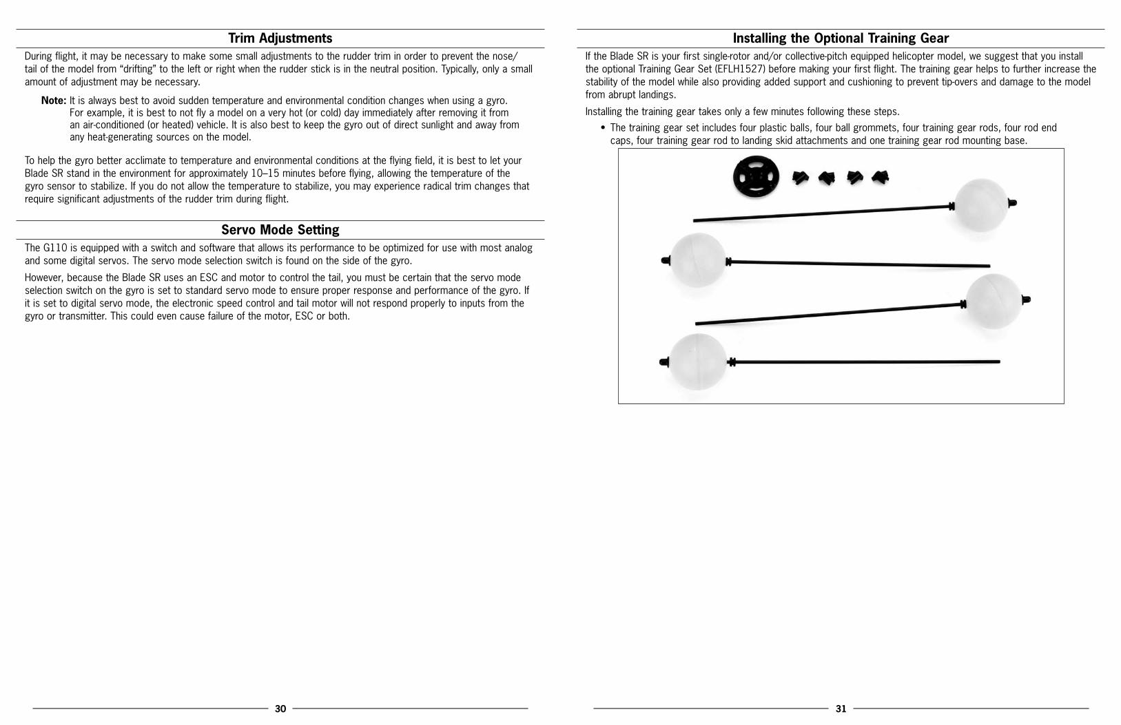
• Thetraininggearsetincludesfourplasticballs,fourballgrommets,fourtraininggearrods,fourrodendcaps, four training gear rod to landing skid attachments and one training gear rod mounting base.
32 33
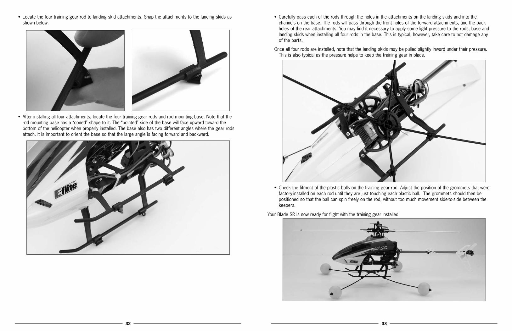
• Locatethefourtraininggearrodtolandingskidattachments.Snaptheattachmentstothelandingskidsasshown below.
• Afterinstallingallfourattachments,locatethefourtraininggearrodsandrodmountingbase.Notethattherodmountingbasehasa“coned”shapetoit.The“pointed”sideofthebasewillfaceupwardtowardthebottom of the helicopter when properly installed. The base also has two different angles where the gear rods attach. It is important to orient the base so that the large angle is facing forward and backward.
• Carefullypasseachoftherodsthroughtheholesintheattachmentsonthelandingskidsandintothechannels on the base. The rods will pass through the front holes of the forward attachments, and the back holes of the rear attachments. You may find it necessary to apply some light pressure to the rods, base and landingskidswheninstallingallfourrodsinthebase.Thisistypical;however,takecaretonotdamageanyof the parts.
Once all four rods are installed, note that the landing skids may be pulled slightly inward under their pressure. This is also typical as the pressure helps to keep the training gear in place.
• Checkthefitmentoftheplasticballsonthetraininggearrod.Adjustthepositionofthegrommetsthatwerefactory-installed on each rod until they are just touching each plastic ball. The grommets should then be positioned so that the ball can spin freely on the rod, without too much movement side-to-side between the keepers.
Your Blade SR is now ready for flight with the training gear installed.

34 35
Understanding the Primary Flight ControlsIf you are not familiar with the controls of your Blade SR, please take a few minutes to familiarize yourself with them before attempting your first flight.
The left-hand stick on the transmitter controls both throttle/collective pitch (climb/descend) and rudder (yaw left/right). When the left-hand stick and throttle trim lever are in their lowest positions, the main rotor blades will not spin. Advancing the stick upward will increase the speed and pitch of the main rotor blades. Increasing the speed and pitch of the main rotor blades will cause the model to climb.
Mode 2 Mode 1
Climb
Decreasing the speed and pitch of the main rotor blades by lowering the left-hand stick will cause the model to descend.
When you are in stunt flight mode (with the F MODE switch toggled toward the front of the transmitter), lowering the left-hand stick will actually cause the speed of the main rotor blades to increase while also increasing the amount of negative pitch the main rotor blades can offer. This allows the model to be flown inverted and to perform basic aerobatic maneuvers.
Mode 2 Mode 1
Descend
After lifting the model off the ground you can balance the throttle/pitch by carefully moving the left-hand stick up and down so the model will hold a stationary hover without climbing or descending.
You can also use the throttle trim to adjust the throttle/collective pitch value for a given stick position. For example, raising the throttle trim will allow the model to hover at a lower throttle stick position. It will also offer more total positive pitch at the highest stick position, and less negative pitch at the lowest position. In most cases it is preferred topositionthethrottletrimsoitoffersanequalamountofpositiveandnegativepitchwhenthestickisinthehighestand lowest positions.

36 37
Also, if you do raise the throttle trim when in the normal flight mode, you MUST remember to lower it (and the throttle stick) to the lowest possible position IMMEDIATELY in the event of a crash or rotor blade strike. Even if the motors are trying to spin at the lowest speed possible, they can still pull enough current to damage the ESCs of the 2-in-1unitiftherotorbladesarestalled,whichmayrequirereplacementofthe2-in-1unit.Ifyouareinthestuntflightmode (and also helpful when you are in the normal flight mode), it is usually best to utilize the throttle hold function of the transmitter in the event of a crash or rotor blade strike by toggling the TH HOLD switch toward the front of the transmitter.
Moving the left-hand stick to the left will turn (yaw) the nose of the helicopter to the left about the axis of the main shaft. This is accomplished by decreasing the speed of the tail rotor blade.
Nose Yaw Left
Mode 2 Mode 1
Moving the stick to the right will turn (yaw) the nose of the helicopter to the right about the axis of the main shaft. This is accomplished by increasing the speed of the tail rotor blade.
Nose Yaw Right
Mode 2 Mode 1

38 39
You can use the rudder trim to help keep the nose of the helicopter from rotating to the left or right when in hover with no rudder stick input. For example, if the nose of the helicopter drifts to the right when in hover, add left rudder trim until the nose stays as close to straight as possible. Also note that further adjustments to the rudder trim can be madeusingthemainmotorproportionalmixtrimmerpotasoutlinedinthe“TailRotorProportionalMixTrimmerPotAdjustment”sectionofthemanual.
The right-hand stick controls both elevator (pitch fore/aft) and aileron (roll). Pushing the stick forward will pitch the nose of the helicopter downward, allowing the helicopter to be flown forward.
Mode 2 Mode 1
Heli Moves Forward
Pulling the stick backward will pitch the tail of the helicopter downward, allowing the helicopter to be flown backward.
Mode 2 Mode 1
Heli Moves Backward
The elevator trim can be used to help keep the helicopter from drifting forward or backward when in hover with no elevator stick input. For example, if the helicopter drifts forward when in hover, pull the elevator trim downward until the helicopter hovers as level as possible with no forward drifting.
40 41
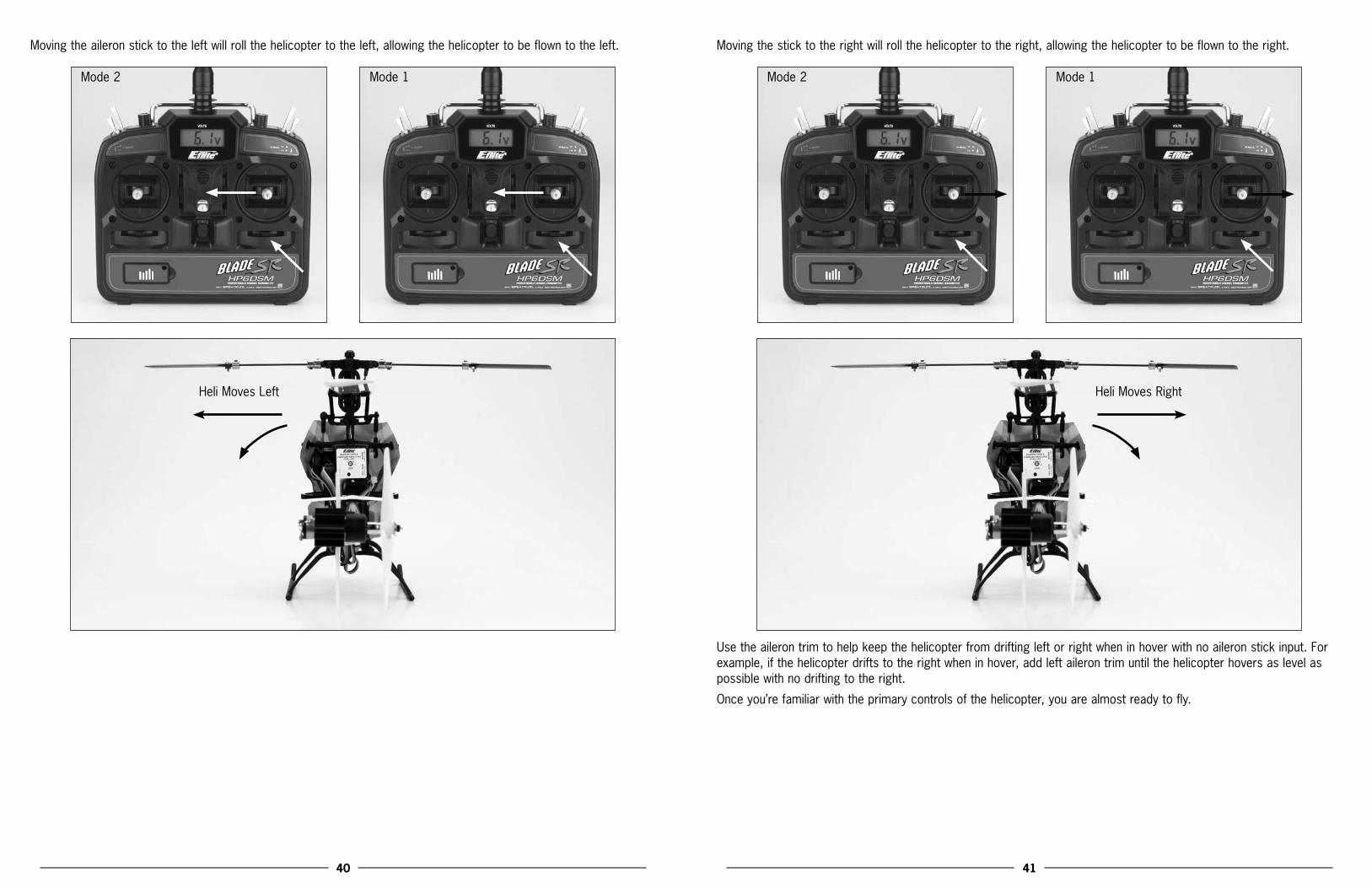
Moving the aileron stick to the left will roll the helicopter to the left, allowing the helicopter to be flown to the left.
Mode 2 Mode 1
Heli Moves Left
Moving the stick to the right will roll the helicopter to the right, allowing the helicopter to be flown to the right.
Mode 2 Mode 1
Heli Moves Right
Use the aileron trim to help keep the helicopter from drifting left or right when in hover with no aileron stick input. For example, if the helicopter drifts to the right when in hover, add left aileron trim until the helicopter hovers as level as possible with no drifting to the right.
Once you’re familiar with the primary controls of the helicopter, you are almost ready to fly.

42 43
Dual Rates The HP6DSM transmitter included with your Blade SR features a dual rate (D RATE) switch. This switch allows the pilot to toggle between the high (HI) and low (LO) control rates available for the aileron, elevator and rudder channels.
Toggling the switch towards the back of the transmitter (position HI) allows the control rates to achieve their highest maximum values. This is typically the preferred rate for experienced pilots interested in more control response for forward flight and basic aerobatic maneuvers.
Toggling the switch toward the front of the transmitter (position LO) allows the control rates to achieve their lowest maximum values. This is typically the preferred rate for low-time and other pilots interested most in a reduced amount of control that allows for smoother and more easily controlled hovering and flying.
IftheBladeSRisyourfirstsingle-rotorand/orcollective-pitchequippedhelicoptermodel,westronglyrecommendthatyou make your first flights with the dual rates set to low.
Note: In order to improve the overall control experience, a small amount of exponential (to reduce the amount of control authority/sensitivity around neutral stick) has been programmed into the transmitter for both the high and low rates.

44 45
Normal and Stunt Flight Modes The HP6DSM transmitter also features a flight mode (F MODE) switch. This switch allows the pilot to toggle between the normal (0) and stunt/idle up (1) flight modes.
F Mode
Toggling the flight mode switch toward the rear of the transmitter (position 0) puts the transmitter/helicopter in normal flight mode. In this flight mode, the throttle curve is programmed from 0% to 100%. This is the preferred flight mode for general hovering.
When the flight mode switch is toggled toward the front of the transmitter (position 1), the transmitter/helicopter will beinthestunt/idleupflightmode.Inthisflightmode,thethrottlecurvecanbe“V”shapedfrom100%to100%withreducedthrottleatmid-stick(whentheSMTCMADJknobisinthelowest,mostcounterclockwiseposition),ora“flat-line”from100%to100%with100%throttleatmid-stick(whentheSMTCMADJknobisinthehighest,mostclockwiseposition). This is the preferred flight mode for most forward/backward flying.
Note: When in stunt mode, even with the throttle stick all the way down, the blades and motors will continue to spin. You must use the normal flight mode to safely turn off the motors. For safety, the 2-in-1 unit will not arm if the flight battery is plugged in and the flight mode switch is in the stunt position.
46 47
Also, when switching between the normal and stunt flight modes, it is best to do so in the air while flying or transitioning to forward flight. There may be a slight change of rotor speed while switching modes, so be aware of the possibility of a slight altitude change. Please be sure to never switch into stunt mode without having powered the main and tail motors up in normal mode first. The abrupt start could cause damage to the gears, motors or possibly even the 2-in-1 unit.
The stunt mode throttle curve midpoint adjustment (SM TCM ADJ) knob is located on the forward top left panel, next to the flight mode switch. This knob allows you to adjust the midpoint value of the throttle curve when in the stunt/idle up flight mode. It has no affect on the throttle curve in the normal flight mode, or on the endpoints of the throttle curve in the stunt/idle up flight mode.
The SM TCM ADJ knob offers you the ability to adjust the main rotor head speed, and in turn the collective and cyclic control response of the model between the endpoints of the throttle curve in the stunt flight mode. Typically, a higher mainrotorheadspeedwillresultinquickercollectiveandcycliccontrolresponsearoundmiddlestick.
For example, when you have the knob in the lowest, most counterclockwise position, the main rotor head speed in hover (and during transition from positive to negative pitch, and vice-versa) will be lower than it is when at the top or bottom of the throttle/collective stick range.
When you have the knob in the highest, most clockwise position, the main rotor head speed in hover (and during transition from positive to negative pitch, and vice-versa) will be similar to when you are at the top or bottom of thethrottle/collectivestickrange.Thisisgenerallypreferredwhenflyinginbreezyconditions,andforthequickestcollective and cyclic response. It is also helpful when performing aerobatics like loops and rolls as it will help to maintain more consistent main rotor head speeds. This also allows for more consistent tail holding power because the torqueandmaintotailmotormixingchangeswillbeminimizedthroughoutthethrottle/collectivestickrange.
Note: Because of the stable settings of the Blade SR, the stunt mode is non-aggressive and basic aerobatics should be flown for the first time with plenty of altitude until you are accustomed to the control response.
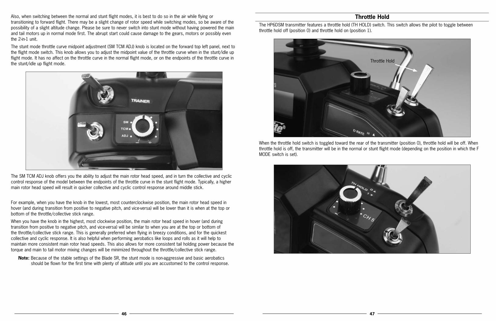
Throttle Hold The HP6DSM transmitter features a throttle hold (TH HOLD) switch. This switch allows the pilot to toggle between throttle hold off (position 0) and throttle hold on (position 1).
Throttle Hold
When the throttle hold switch is toggled toward the rear of the transmitter (position 0), throttle hold will be off. When throttle hold is off, the transmitter will be in the normal or stunt flight mode (depending on the position in which the F MODE switch is set).
48 49
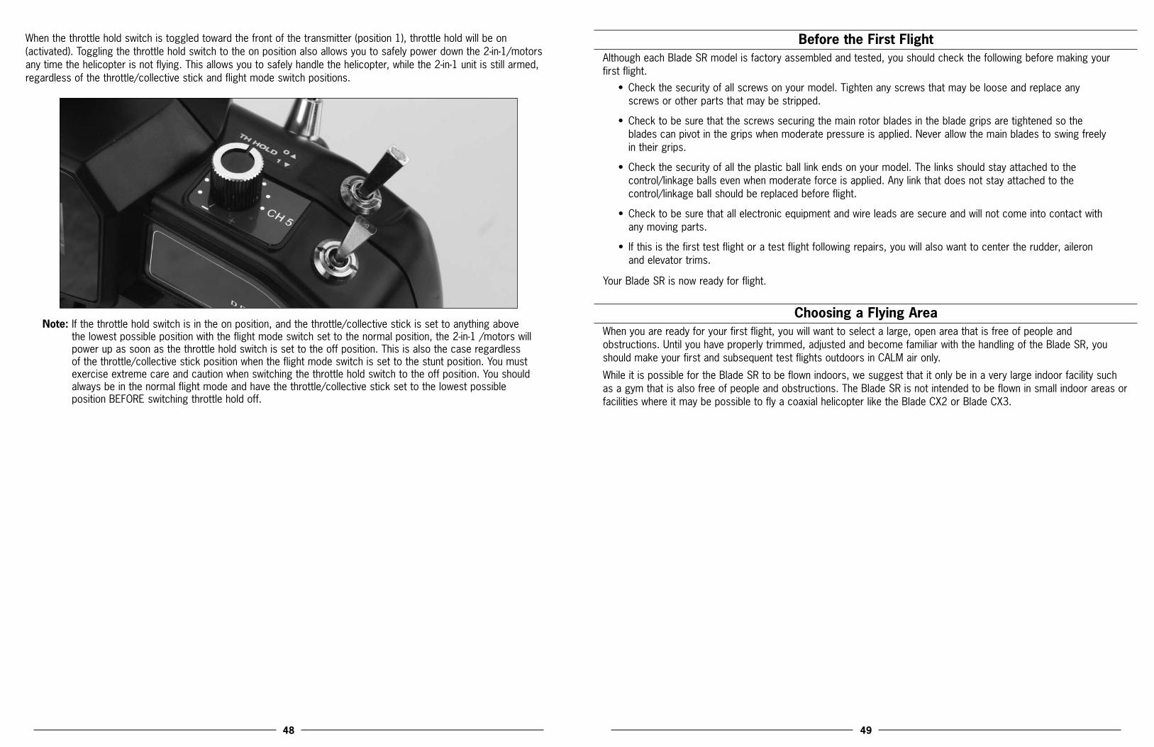
When the throttle hold switch is toggled toward the front of the transmitter (position 1), throttle hold will be on (activated). Toggling the throttle hold switch to the on position also allows you to safely power down the 2-in-1/motors any time the helicopter is not flying. This allows you to safely handle the helicopter, while the 2-in-1 unit is still armed, regardless of the throttle/collective stick and flight mode switch positions.
Note: If the throttle hold switch is in the on position, and the throttle/collective stick is set to anything above the lowest possible position with the flight mode switch set to the normal position, the 2-in-1 /motors will power up as soon as the throttle hold switch is set to the off position. This is also the case regardless of the throttle/collective stick position when the flight mode switch is set to the stunt position. You must exercise extreme care and caution when switching the throttle hold switch to the off position. You should always be in the normal flight mode and have the throttle/collective stick set to the lowest possible position BEFORE switching throttle hold off.
Before the First Flight Although each Blade SR model is factory assembled and tested, you should check the following before making your first flight.
• Checkthesecurityofallscrewsonyourmodel.Tightenanyscrewsthatmaybelooseandreplaceanyscrews or other parts that may be stripped.
• Checktobesurethatthescrewssecuringthemainrotorbladesinthebladegripsaretightenedsotheblades can pivot in the grips when moderate pressure is applied. Never allow the main blades to swing freely in their grips.
• Checkthesecurityofalltheplasticballlinkendsonyourmodel.Thelinksshouldstayattachedtothecontrol/linkage balls even when moderate force is applied. Any link that does not stay attached to the control/linkage ball should be replaced before flight.
• Checktobesurethatallelectronicequipmentandwireleadsaresecureandwillnotcomeintocontactwithany moving parts.
• Ifthisisthefirsttestflightoratestflightfollowingrepairs,youwillalsowanttocentertherudder,aileronand elevator trims.
Your Blade SR is now ready for flight.
Choosing a Flying AreaWhen you are ready for your first flight, you will want to select a large, open area that is free of people and obstructions. Until you have properly trimmed, adjusted and become familiar with the handling of the Blade SR, you shouldmakeyourfirstandsubsequenttestflightsoutdoorsinCALMaironly.
While it is possible for the Blade SR to be flown indoors, we suggest that it only be in a very large indoor facility such as a gym that is also free of people and obstructions. The Blade SR is not intended to be flown in small indoor areas or facilities where it may be possible to fly a coaxial helicopter like the Blade CX2 or Blade CX3.

50 51
Flying the Blade SRHaving followed the proper 2-in-1 control unit arming and gyro initialization procedures, confirmed proper control of the servos and motors, and found a suitable flying area, your Blade SR is ready for flight.
• Slowlyraisethethrottlestick,increasingthespeedofthemainrotorbladesuntilthemodelbeginstoliftoff.Donotraisethethrottlesticktooquicklyasthemodelcouldclimbtoofastcausingyoutolosecontrolormake contact with objects above.
• Liftthemodeloffthegroundjustafewinchesandconcentrateonbalancingtheleft-hand(throttle)stickposition so that the model holds a steady hover altitude. In some cases it may be best to make a few short “hops”toanaltitudeofjustafewinchesuntilyoubecomefamiliarwiththecontrolinputsandtrimsettingsrequiredtomaintainasteadyhoverandaltitude.
Asyouwillfind,theBladeSRrequiresminorthrottle/collectivepitchadjustmentstomaintainitsaltitudeinhover. Remember to keep these adjustments as minimal as possible as large adjustments could result in a loss of control and/or a possible crash.
• Whileattemptingtoestablishalow-levelhover,youcanalsochecktoseeifanytrimadjustmentsarerequiredto help keep the Blade SR from constantly drifting in various directions. If you find the helicopter constantly drifts without any directional control input, it will be best to land the model before making any adjustments to the trim levers. Additional details regarding the locations and functions of the trim lever can be found in the “UnderstandingthePrimaryFlightControls”sectionofthismanual.
If the nose of the helicopter is drifting to the left or right, you will need to adjust the rudder trim. You can also adjust the tail rotor proportional mix if you experience any difficulties in trimming nose drift with the rudder trim lever only. See the“TailRotorProportionalMixTrimmerPotAdjustment”sectionofthismanualformoreinformation.
If the helicopter is drifting forward or backward, you will need to adjust the elevator trim.
If the helicopter is drifting to the left or right, you will need to adjust the aileron trim.
Continue to make trim adjustments until the helicopter can hover at a low altitude with very little drifting and directional control input. If the Blade SR is your first single-rotor and/or collective pitch helicopter model, it may be best to have an experienced helicopter pilot trim the model for you before making your first flight.
Note: You can use the throttle trim to adjust the throttle and collective pitch values for a given throttle stick position. For example, raising the throttle trim will allow the model to hover at a lower throttle stick position.
• OnceyouhavetheBladeSRproperlytrimmedandmaintainingastablelow-levelhover,practiceusingthe rudder, elevator and aileron controls to get a feel for how the helicopter responds to control inputs. Remember to keep the control inputs as minimal as possible to prevent over-controlling the helicopter, especially when in hover.
• WhencomfortablewithhoveringtheBladeSRatlow-levelsofaltitudejustafewinchesofftheground,youcan transition to hovering and flying the helicopter at higher altitudes of approximately three to four feet. At these higher altitudes you will be able to get a feel for the flight characteristics of the helicopter when it is flyingoutof“groundeffect.”
• Don’tbeafraidtosetthehelicopterdownonthegroundquicklybyloweringthethrottlewhenapproachingobstacles to help prevent main rotor blade strikes. Also, the optional training gear set will help to further prevent damage to the helicopter in the event that you must make an abrupt landing to avoid walls or other obstacles when it is installed.
• Ifatanytimeduringflightyoufeellikethehelicopterisdriftingoutofcontrol,itisbesttoreturnallcontrols
to neutral and to lower the throttle stick and trim completely or to activate throttle hold. This will help to reduce the amount of damage that may be caused in the event of a crash.
• INTHEUNFORTUNATEEVENTOFACRASHORROTORBLADESTRIKE,NOMATTERHOWMINORORMAJOR,YOUMUSTLOWERBOTHTHETHROTTLE(LEFT-HAND)STICKANDTHROTTLETRIMTOTHEIRLOWESTPOSSIBLEPOSITION(WHENINTHENORMALFLIGHTMODE)ASQUICKLYASPOSSIBLE TO PREVENT DAMAGE TO THE ESCs OF THE 2-IN-1 UNIT. YOU CAN ALSO ACTIVATE THROTTLEHOLDINANYFLIGHTMODE,REGARDLESSOFTHROTTLESTICKPOSITION.
Failure to lower both the throttle stick and throttle trim to their lowest possible positions (in the normal flight mode only) or to activate throttle hold (in any flight mode) in the event of a crash could result in damage to the ESCs in the 2-in-1 unit,whichmayrequirereplacementofthe2-in-1unit.
While the 2-in-1 control unit main motor and tail motor ESCs are readily capable of handling all in-flight power loads, and even brief momentary bursts beyond these typical loads, they can be damaged if excessive amounts of current are pulled through them for an extended period of time. This period of time may vary depending on many conditions, so it is best to keep any momentary overloads as short as possible in order to prevent damage to the 2-in-1 ESCs.
Note: Crash damage is not covered under warranty.
• ItisextremelyimportantwhenhoveringandflyingtheBladeSRtobeawareofthepowerleveloftheLi-Pobatterypack.Ifatanytimethehelicopterbeginstorequiremorethrottlethantypicaltomaintainhoverorflight, or has lost the ability to maintain hover or flight due to significant loss of power, land the helicopter and power the motors down IMMEDIATELY to prevent over-discharge of the Li-Po battery pack.
If you continue to run the motors after noticing a loss in power it is possible to discharge the Li-Po battery pack too far, causing permanent damage to the pack. Over-discharge of the Li-Po battery pack can result in shortened flight times, loss of power output or failure of the pack entirely.

52 53
Tail Rotor Proportional Mix Trimmer Pot Adjustment After trimming the primary flight controls and becoming familiar with the handling of the model, you may also need to adjust the tail rotor proportional mixing. The proportional trimmer pot adjusts the amount of tail motor to main motor mixing.
Proportional Pot
Afterestablishingastablehover,quicklyadvancethethrottle/collectivestickupwardto“pop”thehelicopterupafewfeet in altitude while adding no rudder input. During the abrupt increase in altitude, note which direction the nose of the helicopter may yaw/turn. If the nose of the helicopter does not yaw in either direction by a significant amount, no adjustment is necessary. However, if the nose of the helicopter yaws to the left, you will want to increase the amount of tail motor to main motor mixing. By turning the proportional trimmer pot clockwise (+), you increase the tail motor/rotor rpm for a given main motor/rotor rpm. This increase in tail motor/rotor rpm will help to push the nose of the helicoptertotherightwhenthereisanabruptchangeintorque.
If the nose of the helicopter tries to yaw to the right, decrease the tail rotor proportional mix by turning the proportional trimmer pot counterclockwise (-).
Note: You must always power down the 2-in-1 control unit before making adjustments to the proportional mix trimmer pot. Any changes made to the trimmer pot will not take effect until the 2-in-1 unit is rearmed.
Main Rotor Blade Tracking AdjustmentCaution:Besuretomaintainasafedistancefromthehelicopter(approximately10–15feet)andtowear
appropriate eye protection (such as safety goggles) when tracking the main rotor blades.
Blade tracking is a critical element to the flight performance of just about any helicopter, including the Blade SR. Main rotor blades that are out of track may cause vibration, instability, and loss of power. Although each Blade SR model is test flown and tracked at the factory, you may need to adjust blade tracking after blade changes, repairs, or pitch control link adjustments.
Tocheckmainrotorbladetrackingandmakeanyrequiredadjustments,pleasenotethefollowingtips:
• Beforeproceedingwiththetestflightofanewmodel,oranymodeltowhichchangesorrepairshavebeenmade, be certain that the main rotor blades have been properly installed and secured. The main blades should be tightened so they can pivot in the blade grip when moderate pressure is applied. Never allow the main blades to swing freely in their grips.
• Afterpoweringthemodelonandallowingthe2-in-1unitandgyrotoarmandinitializeproperly,bringthemain rotor blades of your Blade SR up to speed. You can check the blade tracking either on the ground or in the air at eye level. It might be a good idea to have an assistant on hand to help sight the blades. Again, becertaintomaintainasafedistanceofapproximately10–15feetfromthehelicopterwhencheckingthetracking of the main rotor blades.
• Oncethemainrotorbladeshavebeenbroughtuptospeed,notewhichbladeisrunninglowandwhichbladeis running high (by the colored tracking tape).
Blades Out of Track - Adjustment Necessary
• Afterconfirmingwhichbladeisrunninglowandwhichishigh,powerdownthehelicopterinordertomakeany necessary adjustments to the linkages. You can increase the pitch of the low blade by lengthening its pitch control linkage. This is accomplished by turning one of the Ball Link ends out by one-half to one full turn. Or, you can decrease the pitch of the high blade by shortening the linkage.
Note: The blade you choose to raise or lower when making tracking adjustments will depend on the pitch of each blade. Because both rotor blades should be as close to 0 degrees as possible when throttle hold is activated (DO NOT attempt to check for 0 degrees pitch in the normal or stunt/idle up flight modes) and the throttle/collective stick is in the middle position, you can easily identify which rotor blade to adjust.

54 55
Ifonebladeis“lower”than0degrees,raiseittomatchtheotherblade.Ifonebladeis“higher”than0degrees, lower it to match the other blade.
Typically, not much adjustment should be necessary to properly track the main rotor blades. If significant adjustments arerequired,besuretodouble-checkthelengthofbothpitchcontrollinks(theyshouldbeclosetothesamelength).You should also check the blades for any warps or twists. In most cases, you should be able to get both blades tracking perfectly in the same plane. However, due to slight variations in the ball links and threaded linkage rods/pushrods of the pitch control linkages, it may not always be possible to achieve absolutely perfect blade tracking. Don’t worry, as the helicopter should still perform well as long as the blade tracking is adjusted as closely as possible.
Blades In Track - No Adjustment Necessary
Flybar Paddle Tracking AdjustmentWhile main blade tracking is a critical element of flight performance, proper flybar paddle tracking and positioning is also important in maintaining proper control response and vibration-free operation.
To check flybar paddle tracking, positioning and making adjustments, please note the following tips.
• Confirmthatbothflybarpaddlesareequallyspacedfromtheendsofthepaddlecontrolframe.Iftheyarenotequallyspaced,adjustthepositionoftheflybarbylooseningthesetscrewslocatedinthepaddlecontrolframe, then sliding the flybar from side to side until they are.
• Becertainthatbothflybarpaddlesareparalleltothepaddlecontrolframe.Iftheyarenot,loosenthescrewsand nuts in the flybar paddles and twist the paddles until they are properly aligned and parallel with the paddle control frame.
• Ifyouhavemadecertainthatbothflybarpaddlesareparalleltothepaddlecontrolframearms,theyshouldnow be parallel to one another. If they are not, take your time making adjustments in order to ensure that both flybar paddles are positioned parallel to one another and the paddle control frame.
• Onceyouhaveproperlypositionedandalignedtheflybarpaddlesfollowingthesetips,becertaintheyarefirmly secured using the screws, washers and hex nuts.

56 57
Flybar Weights, Head Dampening Shims and Fine-Tuning Cyclic ResponseYourBladeSRisequippedwithtwosetsofflybarweightsthataresecuredinboththeoutermostpositionagainsttheflybar paddle and the innermost position, closest to the head/main shaft.
Note: The innermost collars are used to secure the paddle control frame and should not be moved.
Movable
Intheouterposition,theweightshelpprovideaddedstabilitybyincreasingtheamountofcyclicinputrequiredtoovercome the gyroscopic force of the flybar paddles. In general, flying with the weights in this position will still provide good cyclic response, but with reduced sensitivity (especially when in hover), when compared to having them positioned closer to the head/main shaft on the flybar. We suggest you make your first flights with the flybar weights in this position before making any adjustments.
If,afterthefirstfewflights,youfeelasthoughthecyclicresponseistooquick,werecommendmovingtheinnersetofweights out, next to the outer set. With both sets in the outer position, the cyclic response will become noticeably less responsive.
If,afterthefirstfewflights,youwouldprefertohaveevenquickerandmoreaggressivecyclicresponse,youcanreposition the outer flybar weights so that they are closer in to the head/main shaft on the flybar. It is usually best tomovetheweightsinonlyasmalldistanceatatimebeforemakingeachsubsequenttestflight,untilyoufindtheposition at which you prefer the cyclic response most.
Note: It is important that the weight(s) on each side of the flybar be positioned at a distance equal from the head/main shaft in order to prevent imbalance that could lead to vibration in the rotor head.
Dampening of the rotor head (main rotor blades) can also be adjusted in order to fine-tune the cyclic response of your model.Ingeneral,stifferdampeningwillresultinquickercyclicresponse.ThedampeningofyourBladeSRhasbeenset to provide good stability right out of the box, and we suggest that you make your first flights with this amount of dampening before making any changes.
If,afterthefirstfewflights,youwouldprefertohavequickercyclicresponse,youcanstiffentherotorheaddampeningbyaddingshimsbetweentheO-ringandstepwasheroneachsideofthecenterhub(seethe“ExplodedView”drawingandpartslistingforreference).Headdampeningshimsareavailableseparatelyinpacksofeight(EFLH1144);however,youshouldinstallonlyoneshimpersideatatimebeforemakingeachsubsequenttestflight,untilyoufindthedampening at which you most prefer the cyclic response (and stability).
Note:Youmustalwaysinstallanequalnumberofshimsoneachsideofthecenterhub.
Note: If you install too many shims, and the dampening becomes too stiff, the helicopter can wobble and shake in flight. Take care when making testing flights after adding shims to prevent crashing the model as a result of a wobble or shake.

58 59
Channel5KnobTheHP6DSMtransmitterisequippedwithanoptional-usechannel5knob(CH5)locatedontheforwardtoprightpanel,next to the dual rate switch.
This knob allows you to control function of the transmitter’s fifth channel. And while this channel remains unused for flying the Blade SR, it is available for use in controlling a variety of potential optional features including actuation of a servo, electronic components or even for setting the gain of a gyro remotely from the transmitter. It allows fully proportionalcontrolofthefifthchannelfromapproximately0–100%travel.
Though servo reversing is available for this channel, the knob can be operated in either direction for control. You can use either the most clockwise (+) or most counterclockwise (-) position for 0 or 100% travel, and you will achieve approximately 50% travel with the knob in the middle position, pointing directly to the rear of the transmitter.
0% (or 100%) Travel
50% Travel
100% (or 0%) Travel
Transmitter, Receiver Binding and Fail-SafeBindingistheprocessofprogrammingthereceivertorecognizetheGUID(GloballyUniqueIdentifier)codeofasinglespecifictransmitter.Ifyoueverhavetoreplacethetransmitterorthereceiverforyourmodel,youwillneedto“bind”the new transmitter or receiver to your existing transmitter or receiver for proper operation.
During the binding process, the smart fail-safe (SmartSafe™) positions of your system are also set. With SmartSafe, in case of loss of signal, the throttle will go to the preset position that was stored during the binding process and all other channels will hold their last position. And if the 2-in-1 control unit and receiver are powered on before the transmitter, all channels but throttle will go to the fail-safe positions that were stored during the binding process, while the throttle channel will not generate a pulse in order to prevent the ESCs from arming.
Note: Because the SmartSafe positions are set during the binding process, it is important to set all channels to the preferred fail-safe positions before proceeding. In the case of the Blade SR, we strongly recommend setting the throttle stick and throttle trim to their lowest positions, and the rudder, aileron and elevator sticks and trims to their neutral positions. Channel 5 should be set to your preferred position if you have chosen to use it.
The following steps outline the binding process:
Note: For added safety, disconnect both the main and tail motors from the 2-in-1 control unit before proceeding. Once the binding process is complete and the flight battery is unplugged from the 2-in-1 unit, reconnect the main and tail motor to the 2-in-1 unit.
• InordertobindtheSpektrumAR6100ereceivertothetransmitter,youmustfirstconnecttheincludedbindplug to the battery (BATT) channel pins on the receiver. Then you will need to power on the 2-in-1 unit and receiver by connecting the flight battery to the 2-in-1 BEFORE powering the transmitter on.
• Whenyouconnecttheflightbatterytothe2-in-1unitwiththebindplugconnectedtothebatterychannelpinson the receiver, you will see an orange LED blink rapidly on the receiver itself.

60 61
• OncetheorangeLEDonthereceiverbeginstoblink,itwillbetimetopowerthetransmitteroninbindmode.To enter bind mode with the transmitter, pull the trainer (TRAINER) switch toward the front of the transmitter, then, while holding the trainer switch forward, power the transmitter on. You’ve successfully entered bind mode when the transmitter beeps and the red LED located under the door on the bottom left front of the transmitter blinks rapidly. You can release the trainer switch after the transmitter stops beeping and the transmitter will remain in bind mode until the binding process is complete.
• Then,oncetheorangeLEDonthereceiverglowssolidly,thereceiverisboundtothetransmitter. Now you will need to power down the 2-in-1 control unit, receiver and transmitter, and remove the bind plug from the receiver.
Note: You will need to remove the bind plug from the receiver once it has been bound to the transmitter. If you do not remove the bind plug, the receiver will enter bind mode every time the 2-in-1 unit and receiver are powered on.
Transmitter and Receiver Range TestingBecause the HP6DSM transmitter features Spektrum 2.4GHz DSM full range technology, it also features a range test modethatallowsyoutocheckandensurethatthetransmitterandreceiverareofferingtherequiredrangeforproperand reliable operation.
Before each flying session, and especially with a new model/receiver, you should perform a range check. To perform a range check, the transmitter must be in the range check/reduced power output mode.
You can enter the range check mode by having the transmitter powered on, then pulling the trainer (TRAINER) switch toward the front of the transmitter. Then, while holding the trainer switch forward, you will need to cycle the dual rate (D RATE) switch from the high position (HI) to the low position (LO) two times (for a total of four dual rate switch position changes).
After cycling the dual rate switch properly while holding the trainer switch, the transmitter should begin to beep. The transmitter is now in range check mode, and will continue to beep and remain in this mode until the trainer switch is released. However, before releasing the trainer switch, it will be necessary to confirm proper range by completing the following steps.
Note: It is helpful to perform the range check with the help of another person that can confirm proper control response of the model while it is positioned away from you.
• Withthemodelrestingontheground,stand30paces(approximately90feet)awayfromthemodel.
• Facethemodelwiththetransmitterinyournormalflyingposition.
• Youshouldhavetotalcontrolofthemodelwiththetrainerswitchpulledat30paces(90feet).
If control issues exist, call the Horizon Hobby Product Support Team at 1-877-504-0233, Horizon Hobby UK at +44 (0) 1279 641 097 or Horizon Technischer Service at +49 4121 46199 66 for further assistance.

62 63
2009 Official AMA Safety CodeGENERAL
1. A model aircraft shall be defined as a non-human-carrying device capable of sustained flight in the atmosphere. It shall not exceed limitations established in this code and is intended to be used exclusively for recreational or competition activity.
2. The maximum takeoff weight of a model aircraft, including fuel, is 55 pounds, except for those flown under the AMA Experimental Aircraft Rules.
3. I will abide by this Safety Code and all rules established for the flying site I use. I will not willfully fly my model aircraft in a reckless and/or dangerous manner.
4. I will not fly my model aircraft in sanctioned events, air shows, or model demonstrations until it has been proven airworthy.
5. I will not fly my model aircraft higher than approximately 400 feet above ground level, when within three (3) miles of an airport without notifying the airport operator. I will yield the right-of-way and avoid flying in the proximity of full-scale aircraft, utilizing a spotter when appropriate.
6. I will not fly my model aircraft unless it is identified with my name and address, or AMA number, inside or affixed to the outside of the model aircraft. This does not apply to model aircraft flown indoors.
7. I will not operate model aircraft with metal-blade propellers or with gaseous boosts (other than air), nor will I operate model aircraft with fuels containing tetranitromethane or hydrazine.
8. I will not operate model aircraft carrying pyrotechnic devices which explode or burn, or any device, which propels a projectile of any kind. Exceptions include Free Flight fuses or devices that burn producing smoke and are securely attached to the model aircraft during flight. Rocket motors up to a G-series size may be used, provided they remain firmly attached to the model aircraft during flight. Model rockets may be flown in accordancewiththeNationalModelRocketrySafetyCode;however,theymaynotbelaunchedfrommodelaircraft. Officially designated AMAAir Show Teams (AST) are authorized to use devices and practices as defined within the Air Show Advisory Committee Document.
9. I will not operate my model aircraft while under the influence of alcohol or within eight (8) hours of having consumed alcohol.
10. I will not operate my model aircraft while using any drug which could adversely affect my ability to safely control my model aircraft.
11. Children under six (6) years old are only allowed on a flightline or in a flight area as a pilot or while under flight instruction.
12.Whenandwhererequiredbyrule,helmetsmustbeproperlywornandfastened.TheymustbeOSHA,DOT,ANSI, SNELL or NOCSAE approved or comply with comparable standards.
RADIO CONTROL
1. All model flying shall be conducted in a manner to avoid overflight of unprotected people.
2.Iwillhavecompletedasuccessfulradioequipmentground-rangecheckbeforethefirstflightofaneworrepaired model aircraft.
3. I will not fly my model aircraft in the presence of spectators until I become a proficient flier, unless I am assisted by an experienced pilot.
4. At all flying sites a safety line or lines must be established, in front of which all flying takes place. Only personnel associated with flying the model aircraft are allowed at or in front of the safety line. In the case
of airshows or demonstrations a straight safety line must be established. An area away from the safety line must be maintained for spectators. Intentional flying behind the safety line is prohibited.
5.Iwilloperatemymodelaircraftusingonlyradio-controlfrequenciescurrentlyallowedbytheFederalCommunications Commission (FCC). Only individuals properly licensed by the FCC are authorized to operate equipmentonAmateurBandfrequencies.
6. I will not knowingly operate my model aircraft within three (3) miles of any preexisting flying site without a frequency-managementagreement.Afrequency-managementagreementmaybeanallocationoffrequenciesfor each site, a day-use agreement between sites, or testing which determines that no interference exists. Afrequency-managementagreementmayexistbetweentwoormoreAMAcharteredclubs,AMAclubsandindividualAMAmembers,orindividualAMAmembers.Frequency-managementagreements,includinganinterference test report if the agreement indicates no interference exists, will be signed by all parties and copiesprovidedtoAMAHeadquarters.
7. With the exception of events flown under official AMA rules, excluding takeoff and landing, no powered model may be flown outdoors closer than 25 feet to any individual, except for the pilot and the pilot’s helper(s) located at the flightline.
8. Under no circumstances may a pilot or other person touch a model aircraft in flight while it is still under power, except to divert it from striking an individual.
9. Radio-controlled night flying is limited to low-performance model aircraft (less than 100 mph). The model aircraftmustbeequippedwithalightingsystemwhichclearlydefinestheaircraft’sattitudeanddirectionatall times.
10. The operator of a radio-controlled model aircraft shall control it during the entire flight, maintaining visual contact without enhancement other than by corrective lenses that are prescribed for the pilot. No model aircraftshallbeequippedwithdeviceswhichallowittobeflowntoaselectedlocationwhichisbeyondthevisual range of the pilot.
FREE FLIGHT
1. I will not launch my model aircraft unless I am at least 100 feet downwind of spectators and automobile parking.
2. I will not fly my model aircraft unless the launch area is clear of all individuals except my mechanic, officials, and other fliers.
3. I will use an effective device to extinguish any fuse on the model aircraft after the fuse has completed its function.
CONTROL LINE
1. I will subject my complete control system (including the safety thong where applicable) to an inspection and pull test prior to flying. The pull test will be in accordance with the current for the applicable model aircraft category.Modelaircraftnotfittingaspecificcategoryshallusethosepull-testrequirementsasindicatedforControl Line Precision Aerobatics.
2. I will ensure that my flying area is clear of all utility wires or poles and I will not fly a model aircraft closer than 50 feet to any above-ground electric utility lines.
3. I will ensure that my flying area is clear of all nonessential participants and spectators before permitting my engine to be started.

64 65
Replacement Parts List
Part # DescriptionEFLA308H 2-in-1 Helicopter Brushless ESC/Mixer: BSREFLB0997 1000mAh 3S 11.1V 15C Li-Po, 20GA JST/BalanceEFLC3105 3-Cell Li-Po Balancing Charger, 0.8AEFLC4000 AC to 12V DC, 1.5 Amp Power SupplyEFLH1057 HP6DSM 6-Channel Transmitter, 2.4GHz DSM2: BSREFLH1115 Bearing 3 x 6 x 2.5mm (2):BCP/P/SR/B400EFLH1143 Spindle: BCP/CPP/SREFLH1146 Rotor Head Set: BCP/CPP/SREFLH1148 Paddle Control Frame: BCP/CPP/SREFLH1149 Flybar (2): BCP/CPP/SREFLH1150 Paddle Set: BCP/CPP /SREFLH1151 Pitch Control Link Set: BCP/CPP/SREFLH1163 Paddle Control Frame Pushrod Set: BCP/CPP/SREFLH1165 Flybar Weight (2): BCP/CPP/SREFLH1171 Bell Mixer Main Blade Grip Set: BCP/CPP/SREFLH1172 Bell Mixer Arm & Pushrod Set: BCP/CPP/SREFLH1215 Bearing 4 x 8 x 3mm (2):BSREFLH1319 Direct-Drive N60 Tail Motor Heat Sink: BCPP2/SREFLH1322 Direct-Drive N60 Tail Motor: BCPP2/SREFLH1323 Direct-Drive Tail Rotor Blade/Prop Adapter: BCPP2/SREFLH1324 Direct-Drive Tail Rotor Blade/Prop: BCPP2/SREFLH1326W Stabilizer/Fin Set, White: BCPP2/SREFLH1409 Pinion Gear, 9T 0.5M: B400/SREFLH1444 Hook and Loop Battery Strap: B400/SREFLH1501 Main Frame: BSREFLH1502 Landing Gear: BSREFLH1503 Tail Boom, Blue: BSREFLH1505 Direct-Drive Tail Motor Mount: BSREFLH1506 Horizontal Stabilizer/Fin Mount: BSREFLH1508 Main Shaft (2): BSREFLH1509 Main Gear: BSREFLH1510 Main Shaft Retaining Collar: BSREFLH1511 Swashplate: BSREFLH1512 Center Hub: BSREFLH1513 O-Ring & Shim Set: BSREFLH1514 Hardware Set: BSREFLH1515 Servo Pushrod Set: BSREFLH1516 3900Kv Brushless Motor: BSREFLH1517 Motor Mount: BSREFLH1518 245mm Wood Main Rotor Blade Set, White: BSREFLH1519 Micro Helicopter Main Blade Holder: BSREFLH1520 Blade SR Canopy, Blue: BSREFLH1522 Canopy Mount Asm: BSREFLH1524 Anti-Rotation Bracket/Guide: BSREFLH1525 Blade Grip Bolts: BCP/CPP/SREFLRG110HL 11.0-Gram G110 Micro Heading Lock GyroEFLRS75H 7.5-Gram DS75 Digital Sub-Micro Helicopter ServoSPMAR6110E AR6110e DSM2 ML 6-Channel Receiver End Pin, Air
Optional Parts List
Part # DescriptionEFLH1528 Hook & Loop Tape: BCP/CPP/BSREFLH1129 Mounting Accessories & Wrench: BCP/CPP/SREFLH1410 Pinion Gear, 10T 0.5M: B400/SREFLH1504 Tail Boom, Black: BSREFLH1507 Tail Motor Wire Lead: BSREFLH1514 Hardware Set: BSREFLH1521 Blade SR Canopy, Red: BSREFLH1523 Spindle/Feathering Shaft (2): BCP/CPP/SR EFLH1527 Training Gear Set: BSR

66 67
EFLA308H2-in-1 Helicopter BrushlessESC/Mixer: BSR
EFLB09971000mAh 3S 11.1V 15C Li-Po,20AWG JST/Balance
EFLH1057HPDSM 6-Channel Transmitter,2.4GHz DSM2: BSR
EFLH1115Bearing 3 x 6 x 2.5mm (2):BCP/P/SR/B400
EFLC31053-Cell Li-Po Balancing Charger, 0.8A
EFLC4000AC to 12V DC, 1.5-Amp Power Supply
EFLH1129Mounting Accessories & Wrench:BCP/CPP/SR
EFLH1143Spindle: BCP/CPP/SR
EFLH1146Rotor Head Set: BCP/CPP/SR
EFLH1148Paddle Control Frame: BCP/CPP/SR
EFLH1449Flybar (2): BCP/CPP/SR
EFLH1150Paddle Set: BCP/CPP/SR
EFLH1151Pitch Control Link Set: BCP/CPP/SR
EFLH1163Paddle Control Frame Pushrod Set:BCP/CPP/SR
EFLH1165Flybar Weight (2): BCP/CPP/SR
EFLH1171Bell Mixer Main Blade Grip Set:BCP/CPP/SR
EFLH1172Bell Mixer Arm & Pushrod Set:BCP/CPP/SR
EFLH1319Direct-Drive N60 Tail Motor Heat Sink:BCPP2/SR
EFLH1322Direct-Drive N60 Tail Motor: BCPP2/SR
EFLH1323Direct-Drive Tail Rotor Blade/PropAdapter: BCPP2/SR
EFLH1324Direct-Drive Tail Rotor Blade/Prop:BCPP2/SR
EFLH1326WStabilizer/Fin Set, White: BCPP2/SR
EFLH1409Pinion Gear, 9T 0.5M: B400/SR
EFLH1410Pinion Gear, 10T 0.5M: B400/SR
EFLH1444Hook and Loop Battery Strap: B4000/SR
EFLRG110HL11.0-Gram G110 Micro HeadingLock Gyro
SPMAR6110EAR6110e DSM2 ML 6-Channel ReceiverEnd Pin, Air
EFLRDS75H7.5-Gram DS75 Digital Sub-MicroHelicopter Servo
EFLH1501Main Frame: BSR
EFLH1503Tail Boom, Blue: BSR
EFLH1504Tail Boom, Black: BSR
EFLH1505Direct-Drive Tail Motor Mount: BSR
EFLH1502Landing Gear: BSR
EFLH1506Horizontal Stabilizer/Fin Mount: BSR
EFLH1507Tail Motor Wire Lead: BSR
EFLH1508Main Shaft (2): BSR
EFLH1509Main Gear: BSR
EFLH1510Main Shaft Retaining Collar: BSR
EFLH1511Swashplate: BSR
EFLH1512Center Hub: BSR
EFLH1513O-Ring & Shim Set: BSR
EFLH1514Hardware Set: BSR
EFLH1515Servo Pushrod Set: BSR
EFLH15163900Kv Brushless Motor: BSR
EFLH1215Motor Mount: BSR
EFLH1518245mm Wood Main Rotor Blade Set,White: BSR
EFLH1519Micro Helicopter Main Blade Holder:BSR
EFLH1520Blade SR Canopy, Blue
EFLH1521Blade SR Canopy, Red
EFLH1522Canopy Mount Assembly: BSR
EFLH1523Spindle/Feathering Shaft (2):BCP/CPP/SR
EFLH1524Anti-Rotation Bracket/Guide: BSR
EFLH1525Blade Grip Bolts: BCP/CPP/SR
EFLH1526Bearing 4 x 8 x 3mm (2): BSR
EFLH1527Training Gear Set: BSR
EFLH1528Hook & Loop Tape: BCP/CPP/BSR

68 69
Ref Part Component
001 EFLH1150 Flybar Paddle 002 EFLH1165 Flybar Weight 1.6 x 6 x 5mm003 EFLH1148 Flybar Retaining Collar
3 x 7 x 5mm004 EFLH1149 Flybar 1.5 x 200mm 005 EFLH1148 Paddle Control Frame 006 EFLH1146 Rotor Head Frame B 007 EFLH1512 Center Hub Cap 008 EFLH1146 Rotor Head Frame A 009 EFLH1146 Rotor Head 010 EFLH1512 Center Hub 011 EFLH1513 O-Ring 2 x 6mm 012 EFLH1151 Pitch Control Link 013 EFLH1151 Pitch Control Rod 1.4 x 10mm014 EFLH1523 Spindle 015 EFLH1163 Paddle Control Frame Pushrod016 EFLH1512 Socket Head Cap Screw 2 x 9mm017 EFLH1513 Shim 3.1 x 5.6 x 0.1mm017 EFLH1172 Shim 3.1 x 5.6 x 0.1mm018 EFLH1171 Step Washer 3.1 x 5.5 x 0.5mm019 EFLH1150 Pan Head Screw 2 x 6mm 020 EFLH1514 Setscrew 3 x 3mm021 EFLH1514 Nut 2mm 022 EFLH1514 Pan Head Screw 2.6 x 6mm023 EFLH1115 Bearing 3x 6 x 2.5mm024 EFLH1514 Pan Head Screw 1.4 x 3mm025 EFLH1171 Brass Spacer 3.1 x 4 x 3.1mm026 EFLH1172 Bell Mixer Arm Pushrod 027 EFLH1171 Blade Grip 028 EFLH1514 Socket Head Cap Screw 2 x 12mm029 EFLH1518 Blades 030 EFLH1514 Flat Washer 2.2 x 5 x 0.5mm031 EFLH1514 Socket Head Cap Screw 2 x 6mm 032 EFLH1172 Bell Mixer Arm 033 EFLH1172 B/M Arm Bushing 2.9 x 3.4 x 7mm034 EFLH1514 Washer- Special
1.8 x 5.2 x 0.1mm035 EFLH1514 Pan Head Screw 1.7 x 4mm 036 EFLH1511 Swashplate 037 EFLH1508 Main Shaft 4 x 79mm038 EFLH1510 Main Shaft Collar 039 EFLH1515 Servo Pushrod 1.6 x 16mm 040 EFLH1515 Servo Pushrod Link 041 EFLH1515 Servo Pushrod 1.6 x 28mm042 EFLH1215 Main Shaft Brg 4 x 8 x 3mm 043 EFLH1509 Main Gear 140T 044 EFLH1501 Right Frame 045 EFLH1501 Left Frame 046 EFLH1514 Pan Head Screw 1.7 x 6mm 047 EFLH1514 Socket Head Cap Screw 2 x 10mm048 EFLH1524 Anti-Rotation Bracket 049 EFLH1522 Canopy Mount Rod 2 x 30mm 050 EFLH1522 Canopy Mount Ends 051 EFLH1502 Landing Gear Asm 052 EFLH1514 Pan Head Screws 1.6 x 6mm
Ref Part Component
053 EFLH1409 Pinion 9T 054 EFLH1514 Pan Head Screw 3 x 6mm055 EFLH1517 Motor Mount 056 EFLH1516 Brushless Motor 057 EFLH1514 Pan Head Screw 2 x 6mm 058 EFLH1503 Tail Boom Blue 7x 8 x 271mm059 EFLH1507 Tail Motor Wire Lead 060 EFLH1506 Lower Horz. Fin Mount 061 EFLH1506 Upper Horz. Fin Mount 062 EFLH1326W Horizontal Fin 063 EFLH1326W Vert Fin 064 EFLH1505 Tail Motor Mount 065 EFLH1514 Flat Washer 2 x 4 x 0.4mm 066 EFLH1514 Pan Head Screw 1.6 x 3mm 067 EFLH1323 Tail Rotor Adapter 068 EFLH1324 Tail Rotor Blade 069 EFLH1514 Flat Washer-Special 2 x 8 x 1.2mm 070 EFLH1322 Tail Motor 071 EFLH1319 Tail Motor Heat Sink 072 EFLDS75H Servos 073 EFLH1515 Control Ball 074 EFLH1514 Flat Head CS Screw 075 EFLH1514 Nylock Nut 2mm 076 EFLRG110HL Gyro077 EFLA308H ESC078 EFLH1514 Hook & Loop Strap 079 EFLH0997 1000mAh 3-Cell Li-Po Battery080 EFLH1520 Canopy 081 SPMAR6110E Receiver082 EFLH1519 Blade Holder 083 EFLH1522 Canopy Grommet
Exploded ViewExploded View Parts Listing
70 71
Age Recommendation: 14 years or over. This is not a toy. This product is not intended for use by children without direct adult supervision.
Warranty InformationWarranty Period
ExclusiveWarranty-HorizonHobby,Inc.,(Horizon)warrantiesthattheProductspurchased(the“Product”)willbefreefrom defects in materials and workmanship at the date of purchase by the Purchaser.
Limited Warranty
(a)ThiswarrantyislimitedtotheoriginalPurchaser(“Purchaser”)andisnottransferable.REPAIRORREPLACEMENTAS PROVIDED UNDER THIS WARRANTY IS THE EXCLUSIVE REMEDY OF THE PURCHASER. This warranty covers only those Products purchased from an authorized Horizon dealer. Third party transactions are not covered by this warranty. Proofofpurchaseisrequiredforwarrantyclaims.Further,Horizonreservestherighttochangeormodifythiswarrantywithout notice and disclaims all other warranties, express or implied.
(b) Limitations- HORIZON MAKES NO WARRANTY OR REPRESENTATION, EXPRESS OR IMPLIED, ABOUT NON-INFRINGEMENT, MERCHANTABILITY OR FITNESS FOR A PARTICULAR PURPOSE OF THE PRODUCT. THE PURCHASER ACKNOWLEDGES THAT THEY ALONE HAVE DETERMINED THAT THE PRODUCT WILL SUITABLY MEET THE REQUIREMENTS OF THE PURCHASER’S INTENDED USE.
(c) Purchaser Remedy- Horizon’s sole obligation hereunder shall be that Horizon will, at its option, (i) repair or (ii) replace, any Product determined by Horizon to be defective. In the event of a defect, these are the Purchaser’s exclusiveremedies.Horizonreservestherighttoinspectanyandallequipmentinvolvedinawarrantyclaim.Repairor replacement decisions are at the sole discretion of Horizon. This warranty does not cover cosmetic damage or damage due to acts of God, accident, misuse, abuse, negligence, commercial use, or modification of or to any part of the Product. This warranty does not cover damage due to improper installation, operation, maintenance, or attempted repair by anyone other than Horizon. Return of any goods by Purchaser must be approved in writing by Horizon before shipment.
Damage Limits
HORIZON SHALL NOT BE LIABLE FOR SPECIAL, INDIRECT OR CONSEQUENTIAL DAMAGES, LOSS OF PROFITS OR PRODUCTION OR COMMERCIAL LOSS IN ANY WAY CONNECTED WITH THE PRODUCT, WHETHER SUCH CLAIM IS BASED IN CONTRACT, WARRANTY, NEGLIGENCE, OR STRICT LIABILITY. Further, in no event shall the liability of Horizon exceed the individual price of the Product on which liability is asserted. As Horizon has no control over use, setup, final assembly, modification or misuse, no liability shall be assumed nor accepted for any resulting damage or injury. By the act of use, setup or assembly, the user accepts all resulting liability.
If you as the Purchaser or user are not prepared to accept the liability associated with the use of this Product, you are advised to return this Product immediately in new and unused condition to the place of purchase.
Law: These Terms are governed by Illinois law (without regard to conflict of law principals).
Safety Precautions
ThisisasophisticatedhobbyProductandnotatoy.Itmustbeoperatedwithcautionandcommonsenseandrequiressome basic mechanical ability. Failure to operate this Product in a safe and responsible manner could result in injury or damage to the Product or other property. This Product is not intended for use by children without direct adult supervision. The Product manual contains instructions for safety, operation and maintenance. It is essential to read and follow all the instructions and warnings in the manual, prior to assembly, setup or use, in order to operate correctly and avoid damage or injury.
Questions, Assistance, and Repairs
Your local hobby store and/or place of purchase cannot provide warranty support or repair. Once assembly, setup or use of the Product has been started, you must contact Horizon directly. This will enable Horizon to better answer yourquestionsandserviceyouintheeventthatyoumayneedanyassistance.Forquestionsorassistance,please
direct your email to [email protected], or call 877.504.0233 toll free to speak to a Product Support representative.
Inspection or Repairs
If this Product needs to be inspected or repaired, please call for a Return Merchandise Authorization (RMA). Pack the Product securely using a shipping carton. Please note that original boxes may be included, but are not designed to withstand the rigors of shipping without additional protection. Ship via a carrier that provides tracking and insurance for lost or damaged parcels, as Horizon is not responsible for merchandise until it arrives and is accepted at our facility. AServiceRepairRequestisavailableatwww.horizonhobby.comonthe“Support”tab.Ifyoudonothaveinternetaccess, please include a letter with your complete name, street address, email address and phone number where you can be reached during business days, your RMA number, a list of the included items, method of payment for any non-warranty expenses and a brief summary of the problem. Your original sales receipt must also be included for warranty consideration. Be sure your name, address, and RMA number are clearly written on the outside of the shipping carton.
Warranty Inspection and Repairs
To receive warranty service, you must include your original sales receipt verifying the proof-of-purchase date. Provided warranty conditions have been met, your Product will be repaired or replaced free of charge. Repair or replacement decisions are at the sole discretion of Horizon Hobby.
Non-Warranty Repairs
Shouldyourrepairnotbecoveredbywarrantytherepairwillbecompletedandpaymentwillberequiredwithoutnotification or estimate of the expense unless the expense exceeds 50% of the retail purchase cost. By submitting the item for repair you are agreeing to payment of the repair without notification. Repair estimates are available upon request.Youmustincludethisrequestwithyourrepair.Non-warrantyrepairestimateswillbebilledaminimumof½hour of labor. In addition you will be billed for return freight. Please advise us of your preferred method of payment. Horizon accepts money orders and cashiers checks, as well as Visa, MasterCard, American Express, and Discover cards. If you choose to pay by credit card, please include your credit card number and expiration date. Any repair left unpaid or unclaimed after 90 days will be considered abandoned and will be disposed of accordingly. Please note: non-warranty repair is only available on electronics and model engines.

72 73
United States
Electronicsandenginesrequiringinspectionorrepairshouldbeshippedtothefollowingaddress:
Horizon Service Center 4105 Fieldstone Road
Champaign, Illinois 61822 USA
AllotherProductsrequiringwarrantyinspectionorrepairshouldbeshippedtothefollowingaddress:
Horizon Product Support 4105 Fieldstone Road
Champaign, Illinois 61822 USA
Pleasecall877-504-0233ore-mailusatproductsupport@horizonhobby.comwithanyquestionsorconcernsregardingthis product or warranty.
UnitedKingdom
Electronicsandenginesrequiringinspectionorrepairshouldbeshippedtothefollowingaddress:
Horizon Hobby UK Units 1-4 Ployters Rd
Staple Tye Harlow, Essex
CM18 7NS United Kingdom
Pleasecall+44(0)1279641097ore-mailusatsales@horizonhobby.co.ukwithanyquestionsorconcernsregardingthis product or warranty.
Germany
Electronicsandenginesrequiringinspectionorrepairshouldbeshippedtothefollowingaddress:
Horizon Technischer Service Hamburger Strasse 10
25335 Elmshorn Germany
Pleasecall+4941214619966ore-mailusatservice@horizonhobby.dewithanyquestionsorconcernsregardingthis product or warranty.
Compliance Information for the European UnionInstructions for Disposal of WEEE by Users in the European Union
This product must not be disposed of with other waste. Instead, it is the user’s responsibility to dispose of theirwasteequipmentbyhandingitovertoadesignatedcollectionpointfortherecyclingofwasteelectricalandelectronicequipment.Theseparatecollectionandrecyclingofyourwasteequipmentatthetimeofdisposal will help to conserve natural resources and ensure that it is recycled in a manner that protects humanhealthandtheenvironment.Formoreinformationaboutwhereyoucandropoffyourwasteequipmentfor recycling, please contact your local city office,your household waste disposal service or where you purchased the product.
The associated regulatory agencies of the following countries recognize the noted certifications for this product as authorized for sale and use:
UK DE DK BG SE
FI EE LV LT PL
CZ SK HU RO SIAT IT ES PT IENL LU MT CY GR
Declaration of Conformity
(in accordance with ISO/IEC 17050-1)
No. HH2009081004
Products: Blade SR RTF Item Numbers: EFLH1500 EquipmentClass: 2
Theobjectofdeclarationdescribedaboveisinconformitywiththerequirementsofthespecificationslistedbelow,following the provisions of the European R&TTE directive 1999/5/EC:
EN 300-328 TechnicalrequirementsforRadioequipment.
EN 301 489-1, 301 489-17 GeneralEMCrequirements
Signed for and on behalf of: Horizon Hobby, Inc. Champaign, IL USA Aug 10, 2009
Steven A. Hall Vice President International Operations and Risk Management Horizon Hobby, Inc.

74 75