rt15 berkeley | requirements on power amplifiers and hil real-time processors to successfully...
TRANSCRIPT

Page 1
WORLDWIDE
AUSTRIAN
POWER
HIL &
Power AmplifierRequirements on Power Amplifiers and HIL
Real-Time Processors to successfully
implement P-HIL Test Benches

Page 2
PI
HIL
Processing
Delay
tPR
ADC
Delay
tPR
Transport
Delay
tTR
Or ionLink
+
-
S igna l
S ou r ce
Pow er
A m p lif ie r
P-HIL Simplified Model
Analogue
Output
Signal
Input
Signal
Page 3
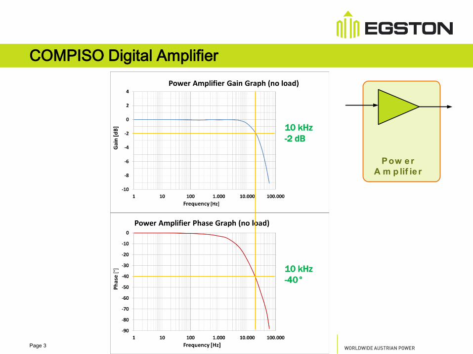
COMPISO Digital Amplifier
Pow er
A m p lif ie r
10 kHz
-2 dB
10 kHz
-40°

Page 4
Orion Link / RT – Link
• tTR = 4µs
• Including:
• HIL Coding
• Transport
• Power Amplifier decoding
Transport
Delay
tTR
Or ionLink
4µs
Page 5
PI
HIL
Processing
Delay
tPR
ADC
Delay
tPR
+
-
S igna l
S ou r ce
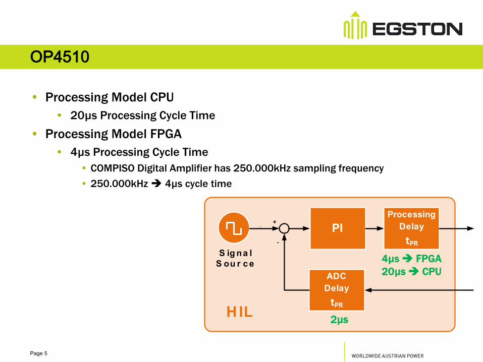
OP4510
• Processing Model CPU
• 20µs Processing Cycle Time
• Processing Model FPGA
• 4µs Processing Cycle Time
• COMPISO Digital Amplifier has 250.000kHz sampling frequency
• 250.000kHz 4µs cycle time
2µs
4µs FPGA
20µs CPU

Page 6
PI
PI Regulator

Page 7
SAMPLING RATES
SIGNAL SOURCE VS
AMPLIFIER
Page 8
HIL
Transport
Delay
tTR
Or ionLink
+
-
S igna l
S ou r ce
Pow er
A m p lif ie r
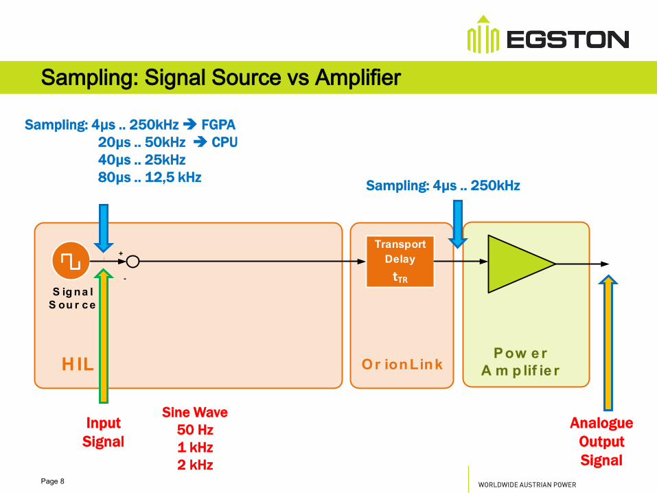
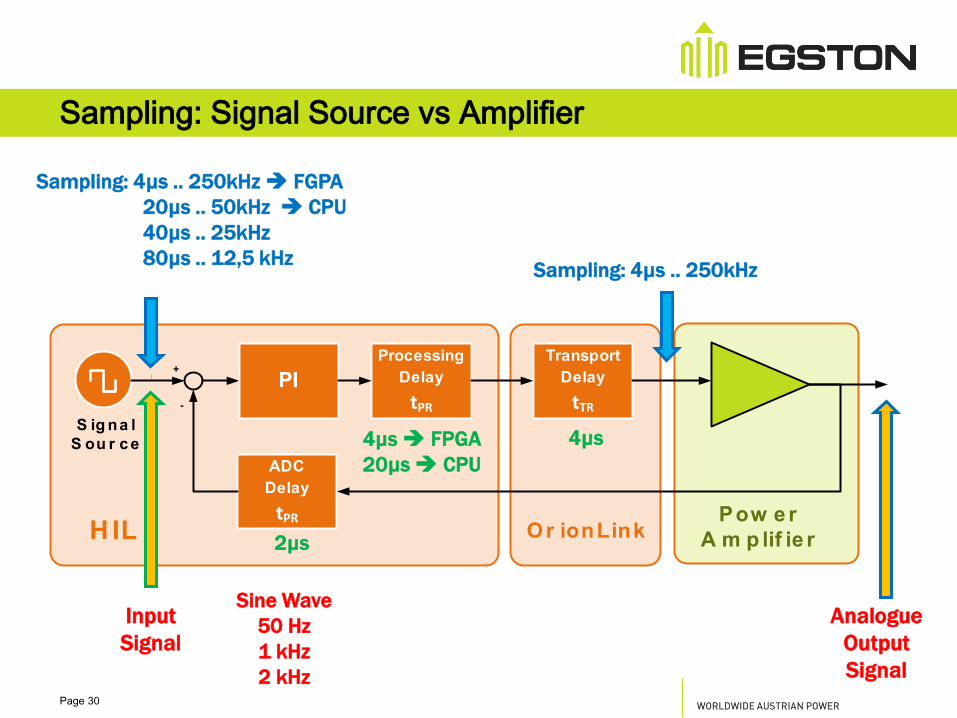
Sampling: Signal Source vs Amplifier
Analogue
Output
Signal
Sampling: 4µs .. 250kHz
Sampling: 4µs .. 250kHz FGPA
20µs .. 50kHz CPU
40µs .. 25kHz
80µs .. 12,5 kHz
Input
Signal
Sine Wave
50 Hz
1 kHz
2 kHz

Page 9
Sine Wave 50 Hz
Set Point: 4µs .. 250kHz
Amplifier Anlogue Output
Sine Wave 50 Hz

Page 10
Sine Wave 50 Hz
Set Point: 80µs .. 12,5 kHz
Amplifier Anlogue Output
Sine Wave 50 Hz

Page 11
Sine Wave 1 kHz
Set Point: 4µs .. 250 kHz FPGA
Amplifier Anlogue Output
Sine Wave 1 kHz

Page 12
Sine Wave 1 kHz
Set Point: 20µs .. 50 kHz CPU
Amplifier Anlogue Output
Sine Wave 1 kHz

Page 13
Sine Wave 1 kHz
Set Point: 40µs .. 25 kHz
Amplifier Anlogue Output
Sine Wave 1 kHz

Page 14
Sine Wave 1 kHz
Set Point: 80µs .. 12,5 kHz
Amplifier Anlogue Output
Sine Wave 1 kHz

Page 15
Sine Wave 2 kHz
Set Point: 4µs .. 250 kHz FPGA
Amplifier Anlogue Output
Sine Wave 2 kHz
Page 16
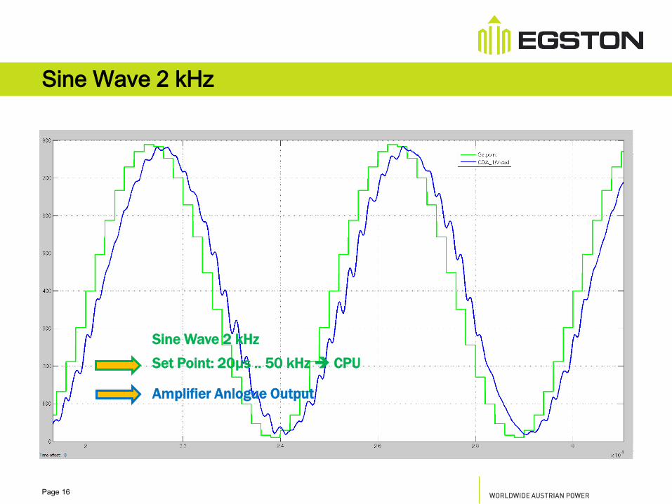
Sine Wave 2 kHz
Set Point: 20µs .. 50 kHz CPU
Amplifier Anlogue Output
Sine Wave 2 kHz

Page 17
Sine Wave 2 kHz
Set Point: 40µs .. 25 kHz
Amplifier Anlogue Output
Sine Wave 2 kHz
Page 18
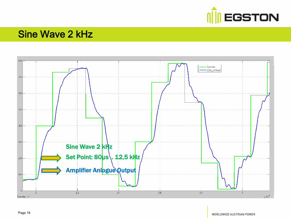
Sine Wave 2 kHz
Set Point: 80µs .. 12,5 kHz
Amplifier Anlogue Output
Sine Wave 2 kHz

Page 19
Summary: Sampling: Signal Source vs Amplifier
• 50 Hz Signals
• Slow CPU Models (>80µs / 12,5 kHz)
• 1 kHz Signal (20th Harmonic)
• Slow CPU Models (>40 µs / 25kHz)
• CPU Model (20 µs / 50 kHz)
• FPGA Model (4 µs / 250 kHz)
• 2 kHz Signal and higher frequencies
• Slow CPU Models (>40 µs / 25 kHz)
• CPU Model (20 µs / 50 kHz)
• FPGA Model (4 µs / 250 kHz)

Page 20
DELAY (DEAD TIME)
VS
PHASE SHIFT

Page 21
HIL
Delays
tDEAD
Or ionLink
+
-
S igna l
S ou r ce
Pow er
A m p lif ie r
Delay vs phase shift
Analogue
Output
Signal
Sampling: 4µs .. 250kHz
Input
Signal
5µs .. 80µs

Page 22
Delay vs phase shift – Phase Graph

Page 23
OPEN LOOP
TRANSFER FUNCTION
Page 24
PI
HIL
Processing
Delay
tPR
ADC
Delay
tPR
Transport
Delay
tTR
Or ionLink
+
-
S igna l
S ou r ce
Pow er
A m p lif ie r
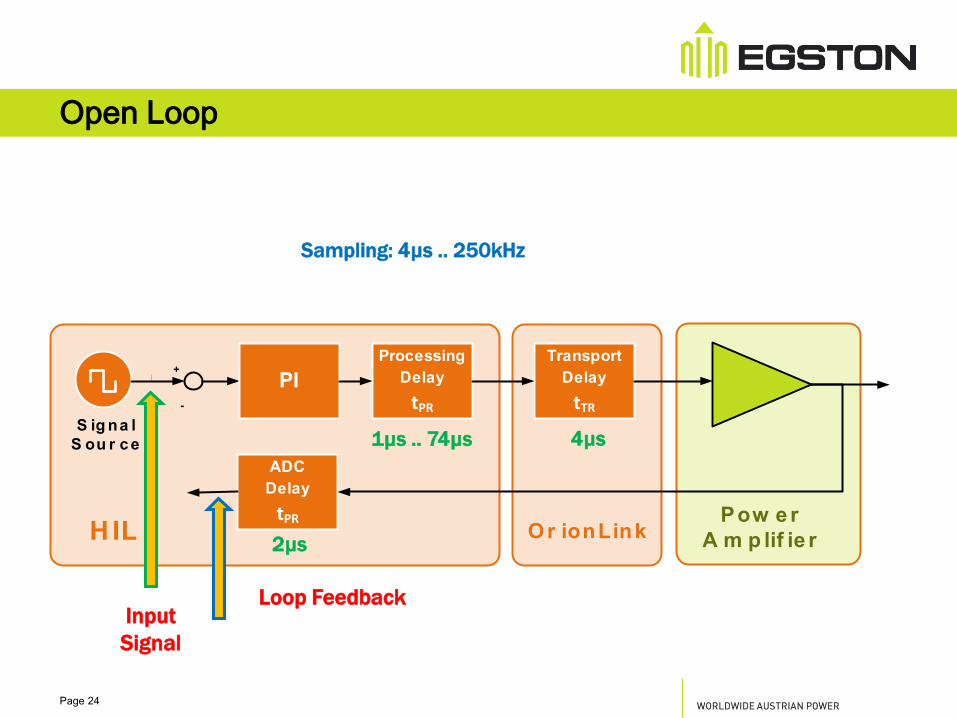
Open Loop
Loop Feedback
Sampling: 4µs .. 250kHz
Input
Signal
1µs .. 74µs 4µs
2µs

Page 25
Open Loop – Transfer Function

Page 26
CLOSED LOOP
SYSTEM STABILITY

Page 27
PI
HIL
Processing
Delay
tPR
ADC
Delay
tPR
Transport
Delay
tTR
Or ionLink
+
-
S igna l
S ou r ce
Pow er
A m p lif ie r
Closed Loop P-HIL
Sampling: 4µs .. 250kHz
Input
Signal
1µs .. 74µs 4µs
2µs

Page 28
Closed Loop – Transfer Function

Page 29
WORLDWIDE
AUSTRIAN
POWER
Thank you…
…for your
Attention
G. Pammer Sept. 2014
Page 30
PI
HIL
Processing
Delay
tPR
ADC
Delay
tPR
Transport
Delay
tTR
Or ionLink
+
-
S igna l
S ou r ce
Pow er
A m p lif ie r
Sampling: Signal Source vs Amplifier
Analogue
Output
Signal
Sampling: 4µs .. 250kHz
Sampling: 4µs .. 250kHz FGPA
20µs .. 50kHz CPU
40µs .. 25kHz
80µs .. 12,5 kHz
Input
Signal
Sine Wave
50 Hz
1 kHz
2 kHz
4µs
2µs
4µs FPGA
20µs CPU

Page 31
PI
HIL
Processing
Delay
tPR
ADC
Delay
tPR
Transport
Delay
tTR
Or ionLink
+
-
S igna l
S ou r ce
Pow er
A m p lif ie r
Sampling: Signal Source vs Amplifier
Analogue
Output
Signal
Sampling: 4µs .. 250kHz
Sampling: 4µs .. 250kHz FGPA
20µs .. 50kHz CPU
40µs .. 25kHz
80µs .. 12,5 kHz
Input
Signal
Sine Wave
50 Hz
1 kHz
2 kHz
4µs
2µs
4µs FPGA
20µs CPU