r&t 2009 - vfds for compressors - cosner
DESCRIPTION
VFDs for Screw CompressorsTRANSCRIPT

Improving Rotary Screw Compressor Performance using Variable Speed Drives
John Cosner, JCI/Frick

A Global Energy Situation….

Efficiency In The Engine Room
Optimum
VFD @ 30% Cap.
S.V. Loaded
Constant Speed
@ 100% Cap.
Constant Speed
@ 100% Cap.
Constant Speed
@ 100% Cap.
Constant Speed
@ 100% Cap.
Constant Speed
@ 30% Cap.
Better
Inefficient
Constant Speed
@ 70% Cap.
Constant Speed
@ 100% Cap.
Constant Speed
@ 60% Cap.
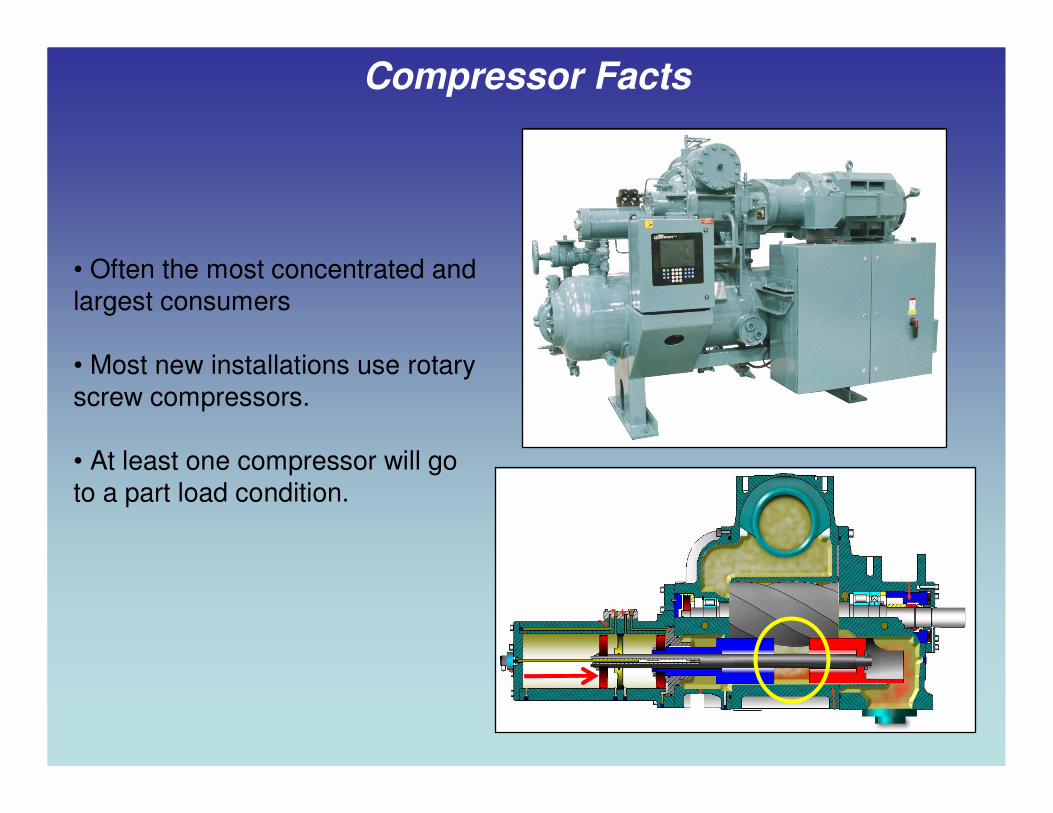
Compressor Facts
• Often the most concentrated and
largest consumers
• Most new installations use rotary
screw compressors.
• At least one compressor will go
to a part load condition.

Constant Torque / Variable Horsepower
Screw Compressors
0%
20%
40%
60%
80%
100%
0% 20% 40% 60% 80% 100%
Speed
To
rqu
e a
nd
Po
wer
HorsepowerTorque
Constant Torque
Horsepower = % Speed
460V / 60Hz = 7.67V : 1Hz

Full Load Power = 500HP / 375KWFull Load Power = 500HP / 375KW
FLA = 580FLA = 580
Running @ 35% Capacity (by speed)Running @ 35% Capacity (by speed)
Voltage = 460vacVoltage = 460vac
HP = 175HP = 175
Amps = 203Amps = 203
Voltage = 161VpwmVoltage = 161Vpwm
HP = 175HP = 175
Amps = 580Amps = 580
MotorMotor
VSDVSD
35% Out35% Out
1260 RPM1260 RPM
21 Hertz21 Hertz
580 Amps580 Amps
132 KW132 KW

0%
20%
40%
60%
80%
100%
0% 20% 40% 60% 80% 100%
Speed
To
rqu
e a
nd
Po
wer
HorsepowerTorque
Variable Torque / Variable HorsepowerPumps & Fans
Torque = % Speed²
Horsepower = % Speed³
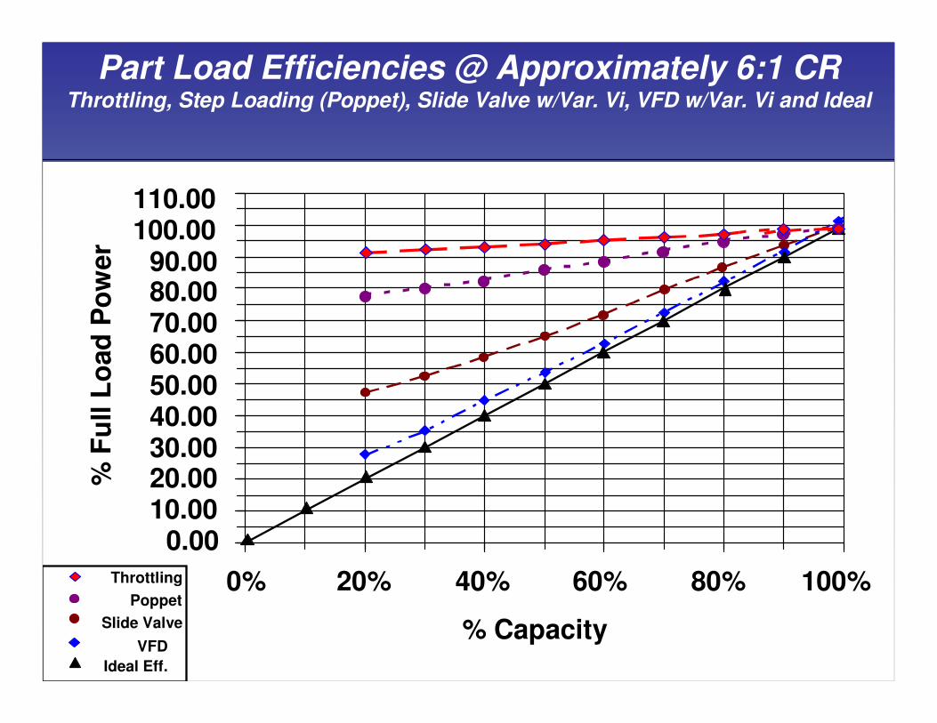
Part Load Efficiencies @ Approximately 6:1 CRThrottling, Step Loading (Poppet), Slide Valve w/Var. Vi, VFD w/Var. Vi and Ideal
0.0010.0020.0030.0040.0050.0060.0070.0080.0090.00
100.00110.00
0% 20% 40% 60% 80% 100%
% Capacity
% F
ull L
oad
Po
wer
Slide Valve
VFD
Ideal Eff.
Poppet
Throttling
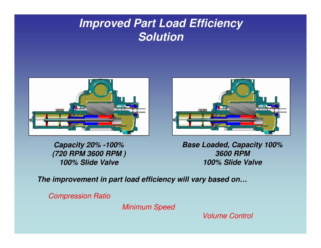
Improved Part Load Efficiency Solution
Compression Ratio
Minimum Speed
Volume Control
Capacity 20% -100% (720 RPM 3600 RPM )
100% Slide Valve
Base Loaded, Capacity 100% 3600 RPM
100% Slide Valve
The improvement in part load efficiency will vary based on…

Compression Ratio (CR)
194.8psiaD / 48.7psiaS 4:1 CR
194.8psiaD / 19.48psiaS 10:1 CR
Example: Improvement at 40% capacity by speed
over 40% capacity by slide valve
4:1 CR = 19% Improvement
10:1 CR = 33% Improvement

Minimum Speed
• Minimum speed established by the limitations of the:
•compressor
•motor
•oil type
•refrigerant.
NH³
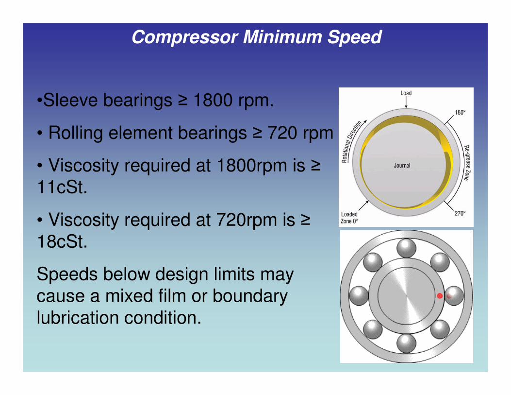
•Sleeve bearings ≥ 1800 rpm.
• Rolling element bearings ≥ 720 rpm
• Viscosity required at 1800rpm is ≥11cSt.
• Viscosity required at 720rpm is ≥18cSt.
Speeds below design limits may cause a mixed film or boundary
lubrication condition.
Compressor Minimum Speed

Oil & Refrigerant
R-22 @ 10˚F (-12˚C)SST1250 RPM Minimum
R-717@ 20˚F (-6.5˚C)SST720 RPM Minimum
R-22 @ 20˚F (-6.5˚C)SST 1500 RPM Minimum

Motor Minimum Speed
• An issue of bearings and heat rejection.
• Air-flows at speeds below
50% speed may not be
adequate.
• Check with manufacturer for
minimum speed.
• Motor stator temperature
protection is now required (NEC 2005).
Fractional HP Squirrel Cage
Fan/s Ensure Adequate Air
Flow At All Speeds
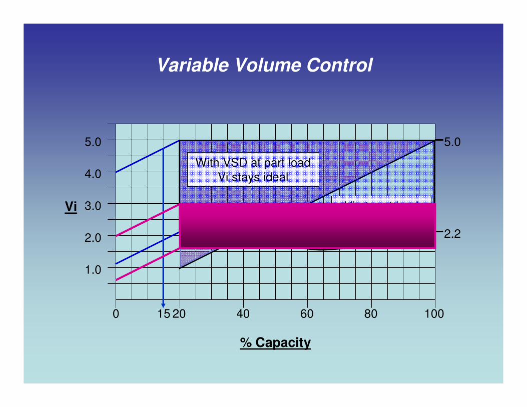
Variable Volume Control
100806040200
5.0
4.0
3.0
2.0
1.0
5.0
2.2
Vi at part load
by slide valve
% Capacity
Vi
15
With VSD at part load
Vi stays ideal

% Capacity to % Capacity to
% Slide Valve Position% Slide Valve Position
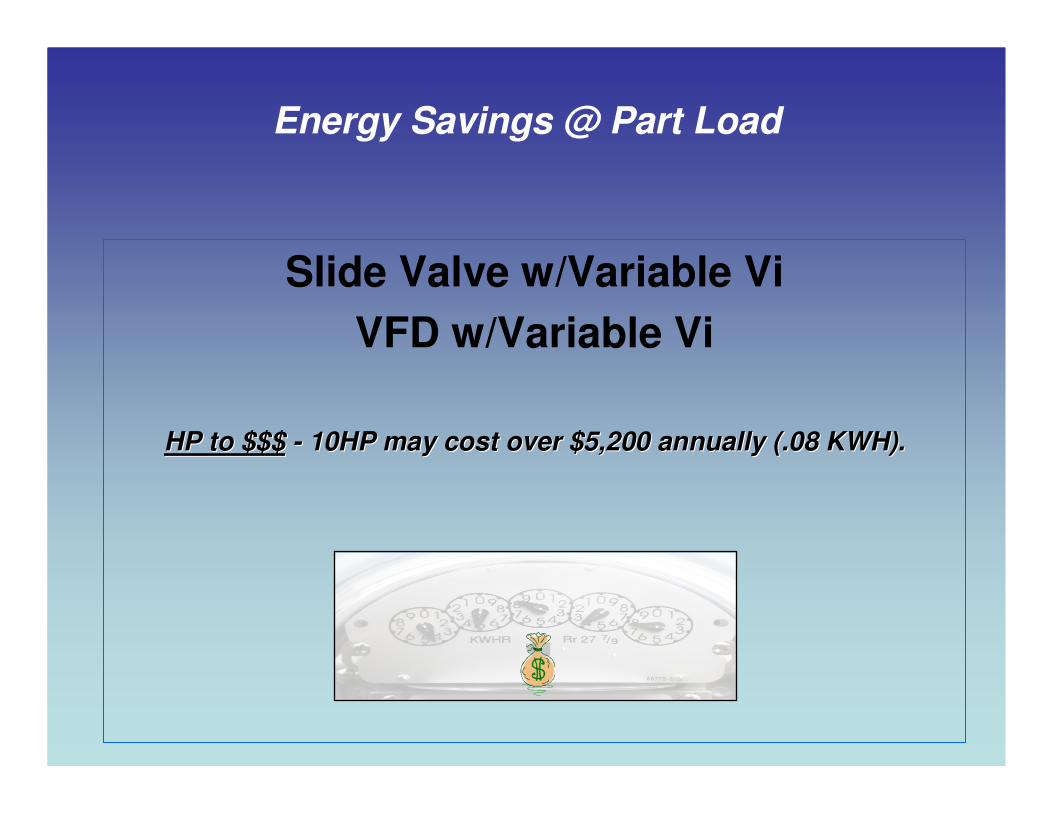
Slide Valve w/Variable Vi
VFD w/Variable Vi
HP to $$$HP to $$$ -- 10HP may cost over $5,200 annually (.08 KWH).10HP may cost over $5,200 annually (.08 KWH).
Energy Savings @ Part Load

RWFII-270 @ 20˚F (-6.7˚C) SST / 95˚F (35˚C) SDT 4.06:1 CR on Ammonia
Slide Valve, VFD and Ideal Part Load Efficiencies
0.0050.00
100.00150.00200.00250.00300.00350.00400.00450.00500.00550.00600.00650.00700.00
0% 20% 40% 60% 80% 100%
% Capacity
Ho
rse P
ow
er
S.V. Control
VFD Control
650HP
19
HP
52
HP
107
HP

RWFII-270 @ 20˚F (-6.7˚C) SST / 75˚F (24˚C) SDT / 2.9:1 CR on Ammonia
Slide Valve, VFD and Ideal Part Load Efficiencies
0.00
50.00
100.00
150.00
200.00
250.00
300.00
350.00
400.00
450.00
500.00
0% 20% 40% 60% 80% 100%
% Capacity
Ho
rse P
ow
er
S.V. Control
VFD Control
9
HP
31
HP
62
HP
475HP

0.00
50.00
100.00
150.00
200.00
250.00
300.00
350.00
400.00
450.00
0% 20% 40% 60% 80% 100%
% Capacity
Ho
rse P
ow
er
RWFII-270 @ -40˚F (-40˚C) SST / 95˚F (35˚C) SDT / 18.75:1 CR on Ammonia
Slide Valve, VFD and Ideal Part Load Efficiencies
26
HP
137
HP
82
HP
420HPS.V. Control
VFD Control

RWFII-270 @ -40˚F (-40˚C) SST / 75˚F (24˚C) SDT / 13.45:1 CR on Ammonia
Slide Valve, VFD and Ideal Part Load Efficiencies
335HPS.V. Control
VFD Control
0.00
50.00
100.00
150.00
200.00
250.00
300.00
350.00
0% 20% 40% 60% 80% 100%
% Capacity
Ho
rse P
ow
er
18
HP
60
HP
102
HP
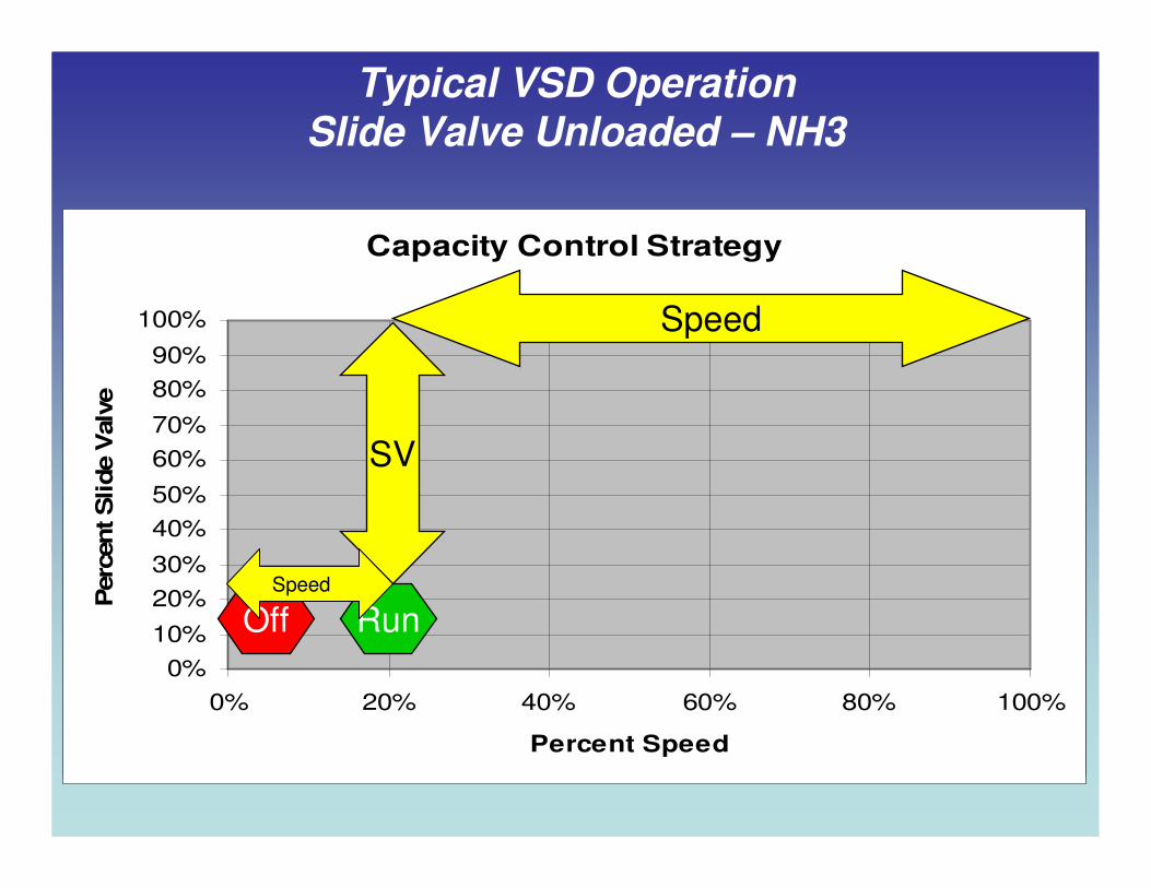
Capacity Control Strategy
0%
10%
20%
30%
40%
50%
60%
70%
80%
90%
100%
0% 20% 40% 60% 80% 100%
Percent Speed
Perc
ent S
lide V
alv
e
Capacity Control Strategy
0%
10%
20%
30%
40%
50%
60%
70%
80%
90%
100%
0% 20% 40% 60% 80% 100%
Percent Speed
Perc
ent S
lide V
alv
e
Off Run
SV
Speed
Speed
Typical VSD OperationSlide Valve Unloaded – NH3

Typical VSD OperationSlide Valve Loaded – NH3
Capacity Control Strategy
0%
10%
20%
30%
40%
50%
60%
70%
80%
90%
100%
0% 20% 40% 60% 80% 100%
Percent Speed
Perc
ent S
lide V
alv
e
Off Run SpeedSVSpeed
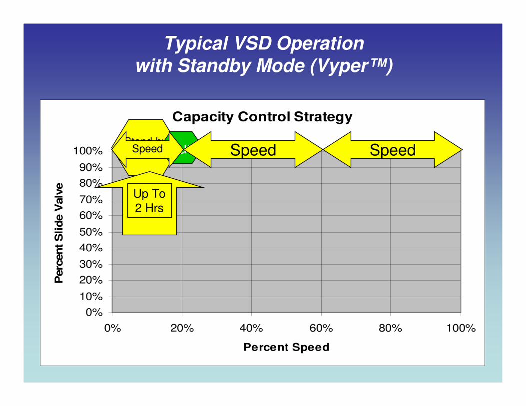
Typical VSD Operationwith Standby Mode (Vyper™)
Up To
2 Hrs.
Capacity Control Strategy
0%
10%
20%
30%
40%
50%
60%
70%
80%
90%
100%
0% 20% 40% 60% 80% 100%
Percent Speed
Perc
en
t S
lide V
alv
e
Stand-byat 100%SVRunSpeed Speed Speed
Up To
2 Hrs

Economizing
Econo. Improvement of HP/TR -40F/95F
0
2
4
6
8
10
12
14
0 50 100 150
Tons
HP
/TR
Non E SV
Econ VSD
Non E VSD
Econ SV
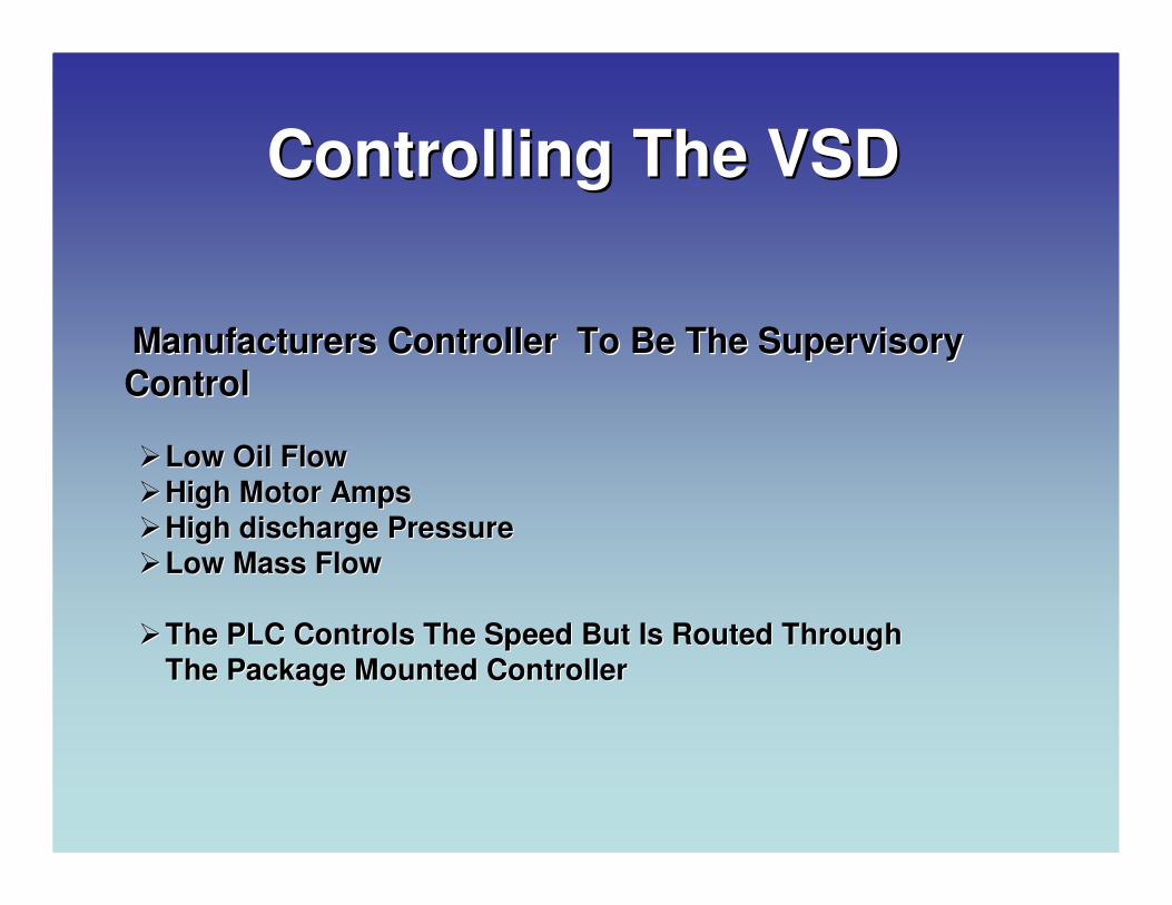
Controlling The VSDControlling The VSD
Manufacturers Controller To Be The Supervisory Manufacturers Controller To Be The Supervisory
ControlControl
��Low Oil FlowLow Oil Flow
��High Motor AmpsHigh Motor Amps
��High discharge PressureHigh discharge Pressure
��Low Mass FlowLow Mass Flow
��The PLC Controls The Speed But Is Routed Through The PLC Controls The Speed But Is Routed Through
The Package Mounted ControllerThe Package Mounted Controller

VSD Control with Quantum LX
Capacity Control Setup

Motor & Drive Setup
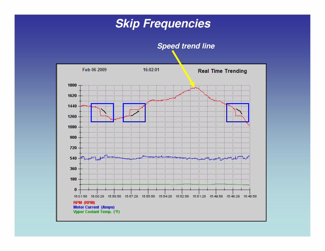
Skip Frequencies
Speed trend line
Can I Retrofit My Existing Equipment???
VSD?

• Ensure the VSD is constant
torque.
• Motor is inverter duty rated.
• Minimum speed is identified.
• Ensure environment is
adequate.
• Total cable distance between
drive and motor is within spec.
• Controller is able to protect
the compressor as well as control the drive.
Retrofitting Existing Equipment For Energy Savings

To VSD or Not To VSD?
Qualifying Expense Through Savings (ROI)
Total Load Profile
1. Hours of Operation?
2. Compression Ratio?
3. Cost per KWH?
4. Part Load Profile?
How Do I Accurately Get This Information?
Items 1-3 Are Easy
What is My
Part Load
Profile?
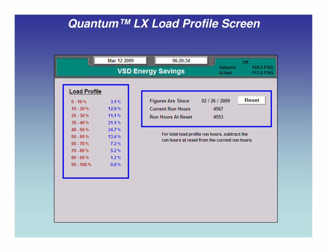
Quantum™ LX Load Profile Screen
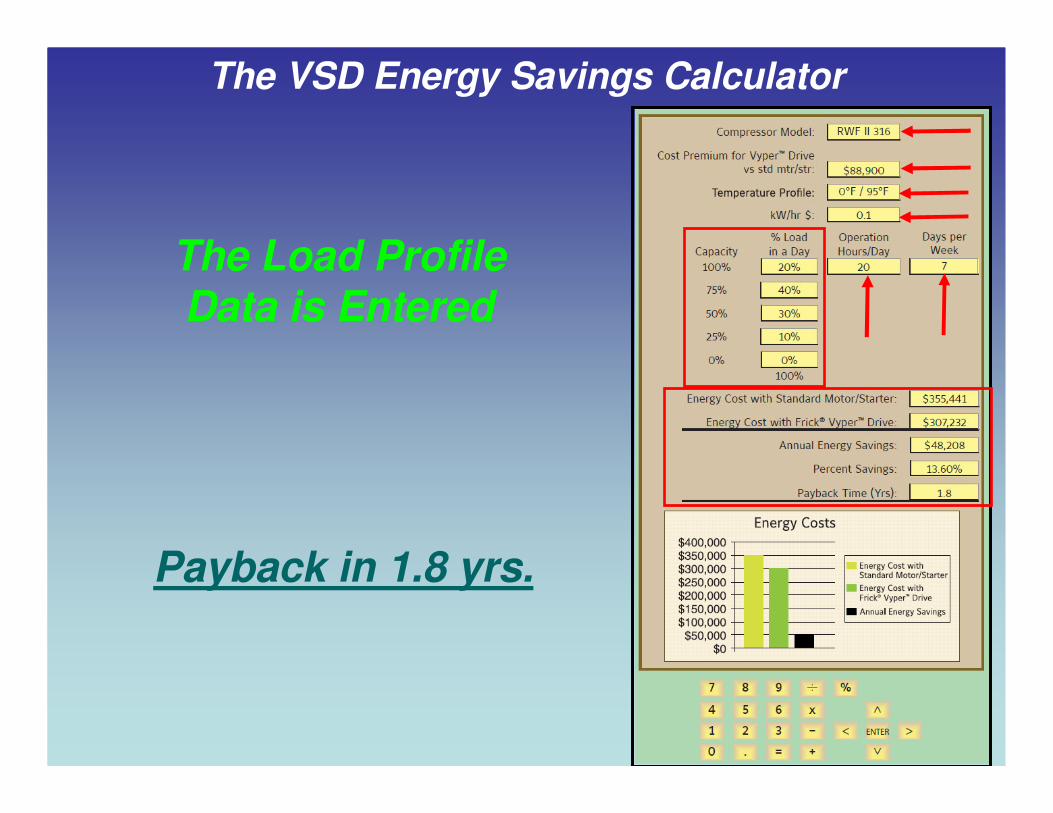
The Load Profile Data is Entered
The VSD Energy Savings Calculator
Payback in 1.8 yrs.
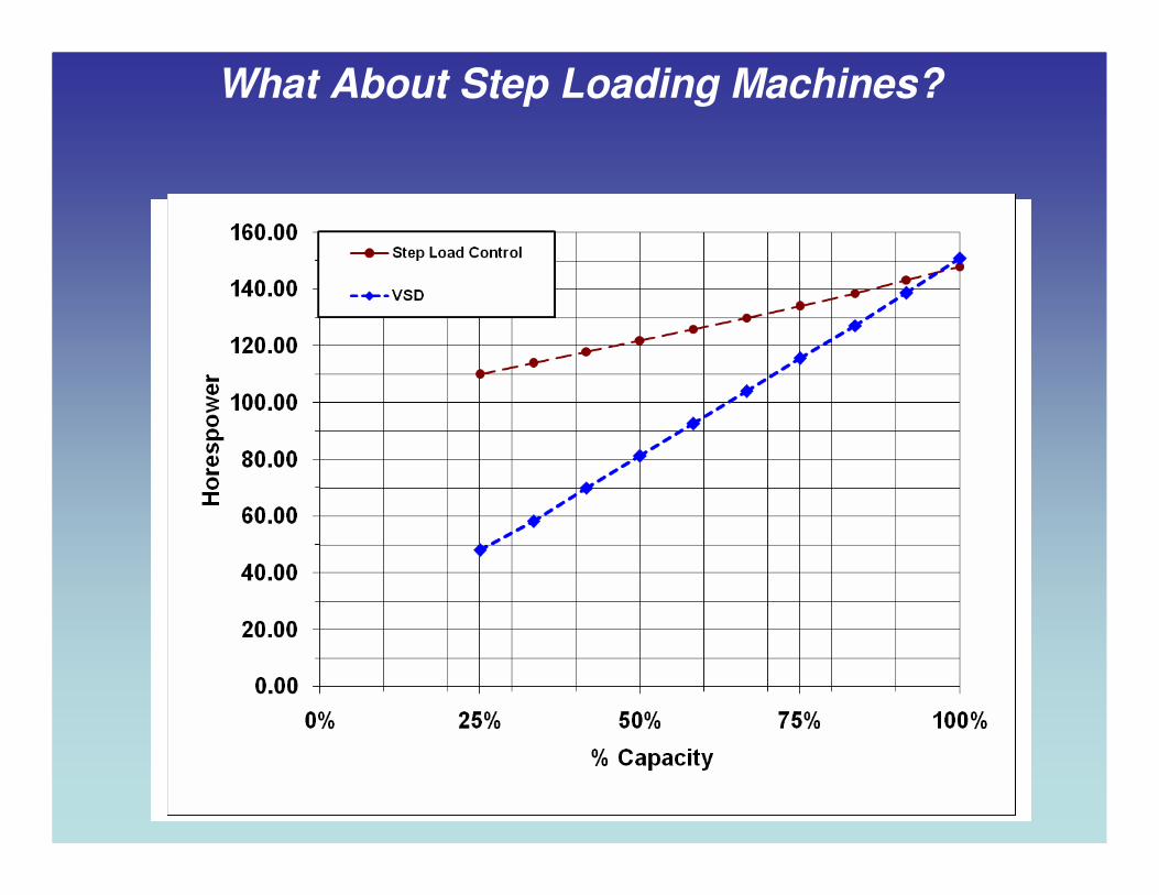
What About Step Loading Machines?
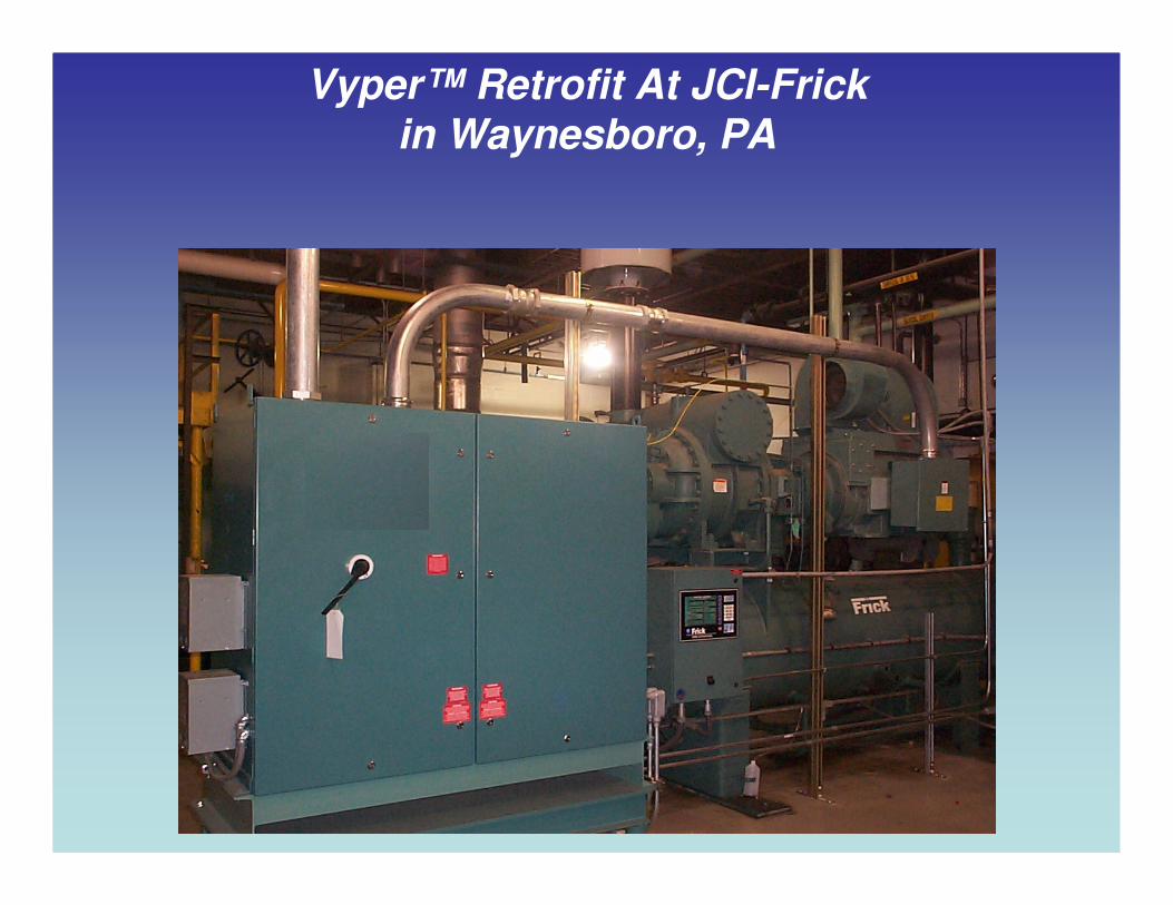
Vyper™ Retrofit At JCI-Frick in Waynesboro, PA

In ConclusionIn Conclusion………………....
When Properly Applied, VSDs On Rotary Screw When Properly Applied, VSDs On Rotary Screw
Compressors Can:Compressors Can:
�� Lower Energy Usage & CostLower Energy Usage & Cost
�� Enhance Economizer BoostEnhance Economizer Boost
�� Remove Setpoint OverRemove Setpoint Over--ShootShoot
�� Provide Quicker Response To Load FluctuationProvide Quicker Response To Load Fluctuation
�� Keep Capacity Slides Fully LoadedKeep Capacity Slides Fully Loaded
�� Reduce Maintenance CostsReduce Maintenance Costs
�� Reduce Noise LevelsReduce Noise Levels
�� Properly Applied Is The Properly Applied Is The Key!Key!
Thank You!Thank You!