rslogix 500 - plc compareplccompare.com/wp-content/uploads/2011/03/rslogix500.pdf · trademark...
TRANSCRIPT

LG500_GR002C-EN-P 1/23/08 3:28 PM Page 1
RSLogix 500™
GETTING RESULTS GUIDEPUBLICATION LG500-GR002C-EN-P–January 2007
Supersedes Publication LG500-GR002B-EN-P

Contact Rockwell Customer Support Telephone — 1.440.646.3434Online Support — http://support.rockwellautomation.com
Copyright Notice © 2007 Rockwell Automation Technologies, Inc. All rights reserved. Printed in USA.This document and any accompanying Rockwell Software products are copyrighted by Rockwell Automation Technologies, Inc. Any reproduction and/or distribution without prior written consent from Rockwell Automation Technologies, Inc. is strictly prohibited. Please refer to the license agreement for details.
Trademark Notices Allen-Bradley, FactoryTalk, Rockwell Automation, Rockwell Software, RSLinx, RSView, and the Rockwell Software logo are registered trademarks of Rockwell Automation, Inc.
The following logos and products are trademarks of Rockwell Automation, Inc.:RSLogix.Advanced Interface (A.I.) Series, A.I. Series, Data Highway Plus, DH+, RSView.FactoryTalk Activation, FactoryTalk Administration Console, FactoryTalk Automation Platform, FactoryTalk Directory, RSAssetSecurity, FactoryTalk Security, and RSSql.MicroLogix, RSLinx Classic, RSLinx Enterprise, SLC 5, and SLC 500.
Other Trademarks ActiveX, Microsoft, Microsoft Access, SQL Server, Visual Basic, Visual C++, Visual SourceSafe, Windows, Windows ME, Windows NT, Windows 2000, Windows Server 2003, and Windows XP are either registered trademarks or trademarks of Microsoft Corporation in the United States and/or other countries.Adobe, Acrobat, and Reader are either registered trademarks or trademarks of Adobe Systems Incorporated in the United States and/or other countries.ControlNet is a registered trademark of ControlNet International.DeviceNet is a trademark of the Open DeviceNet Vendor Association, Inc. (ODVA).Ethernet is a registered trademark of Digital Equipment Corporation, Intel, and Xerox Corporation.OLE for Process Control (OPC) is a registered trademark of the OPC Foundation.Oracle, SQL*Net, and SQL*Plus are registered trademarks of Oracle Corporation.All other trademarks are the property of their respective holders and are hereby acknowledged.
Warranty This product is warranted in accordance with the product license. The product’s performance may be affected by system configuration, the application being performed, operator control, maintenance, and other related factors. Rockwell Automation is not responsible for these intervening factors. The instructions in this document do not cover all the details or variations in the equipment, procedure, or process described, nor do they provide directions for meeting every possible contingency during installation, operation, or maintenance. This product’s implementation may vary among users.This document is current as of the time of release of the product; however, the accompanying software may have changed since the release. Rockwell Automation, Inc. reserves the right to change any information contained in this document or the software at anytime without prior notice. It is your responsibility to obtain the most current information available from Rockwell when installing or using this product.
Version: 7.30.xx (CPR 7)Modified: June 28, 2007 9:02 am
ii

Preface
Purpose of this bookThis Getting Results book provides you with information on how to install and navigate the RSLogix 500 software. This guide includes troubleshooting information and tips on how to use RSLogix 500 effectively. It also explains how to access and navigate the online help.
Intended audienceWe assume that you are a control engineer familiar with:
IBM-compliant personal computersMicrosoft Windows 2000™, Windows XP™ ,Windows Server 2003™, or Windows Server 2003™ R2. Rockwell Automation’s SLC 500™ and MicroLogix™ families of controllers
Document conventionsThis manual uses the following typographical conventions:
[Bold] characters in brackets represent keystrokes used to execute a function. When more than one key is to be pressed at a time, the keys are separated by a plus sign. For example, [Ctrl + v] means hold down the [Ctrl] key and press the [v] key.Bold characters represent menu choices.TEXT IN THIS FONT represents characters that you should type.
Online helpIf you need help while using RSLogix 500, use any of the following methods:
choose Help from the menu barclick the Help button on any RSLogix 500 dialogpress [F1] on any instruction, dialog box, or window view.
For more information about the online help refer to RSLogix 500 online help on page 91.
Preface n iii

TrainingRockwell Software offers both classroom training and a computer-based training program for RSLogix 500 software. For more information see RSLogix 500 Training on page 95.
Commonly used termsThe following table defines terms commonly used in this book.
This term: Represents this concept:
activation files Hidden files in the root folder that allow the software to run. The software checks for these files before you have access to offline or online programming
back up To make a copy of the current file before replacing that file with an updated version.
download Restore a specified file to a specified processor. For example, when you download the current project file, you copy the file to a specified processor so the processor can begin running that file.
library A file into which you store or from which you retrieve portions of ladder logic.
mnemonic A term, usually an abbreviation that is easy to remember. SLC instructions are typically represented by a 3-letter mnemonic.
project All of the files that make up the SLC 500 logic program including the documentation files.
upload Access an SLC processor and save a copy of the project.
verification An analysis of the ladder program files that results in the display of any programming errors.
zone Portion of the ladder logic identified by a marker indicating the edited state of the file.
iv n Getting Results with RSLogix 500™

ContentsPreface .................................................................................... iii
Purpose of this book ................................................................................................................ iiiIntended audience ..................................................................................................................... iiiDocument conventions............................................................................................................ iiiOnline help................................................................................................................................. iiiTraining....................................................................................................................................... ivCommonly used terms ............................................................................................................. iv
Chapter 1Installing RSLogix 500.............................................................. 1
Introduction ................................................................................................................................1System requirements..................................................................................................................1
Hardware requirements.......................................................................................................................1Software requirements ........................................................................................................................2
Activation ....................................................................................................................................2Installing RSLogix 500 software ..............................................................................................3
Installing RSLinx Classic Lite software ............................................................................................3Installing the FactoryTalk Automation Platform............................................................................4Installing the FactoryTalk Activation Client....................................................................................6Installing the Security Server Client ..................................................................................................8Installing RSLogix 500 ........................................................................................................................9
Upgrading the FactoryTalk Platform ....................................................................................11Upgrading a Stand-Alone System on a Single Computer ........................................................... 11Upgrading a Distributed FactoryTalk System on a Network .................................................... 12
Importing a Security Configuration from the Rockwell Software Security Server into FactoryTalk Security ................................................................................................................15Configuring FactoryTalk Security for RSLogix 500 ...........................................................16
Setting Security Policies for RSLogix 500 ..................................................................................... 17Securing Actions for RSLogix 500 ................................................................................................. 20
Starting RSLogix 500 software...............................................................................................28Troubleshooting installation...................................................................................................28
Table of Contents • v

Chapter 2Getting started with RSLogix 500 ..........................................31
Welcome to RSLogix 500....................................................................................................... 31Exploring RSLogix 500 .......................................................................................................... 32Quick Start Steps ..................................................................................................................... 33
Step 1 • Configure a driver in RSLinx Classic.......................................................................... 34Step 2 • Configure system communications............................................................................. 36Step 3 • Create a new project or open an existing project ..................................................... 38Step 4 • Create program and data table files ............................................................................ 40Step 5 • Define chassis and modules......................................................................................... 41Step 6 • Enter a logic program ................................................................................................... 41Step 7 • Add documentation to your logic instructions ......................................................... 43Step 8 • Validate your project ..................................................................................................... 44Step 9 • Configure communication channel, download and go online................................ 45Step 10 • Monitor data files........................................................................................................... 45Step 11 • Search and replace instructions ................................................................................... 46Step 12 • Print a report .................................................................................................................. 47
Chapter 3Chassis and module setup ......................................................49
Power supply loading .............................................................................................................. 50Analog and specialty module configuration ........................................................................ 50Automatic I/O configuration................................................................................................ 50
Chapter 4Entering ladder logic...............................................................51
Backing up your work ............................................................................................................. 51Crash Recovery.................................................................................................................................. 52
Quick entry of instructions .................................................................................................... 53Addressing ................................................................................................................................ 54Branching.................................................................................................................................. 55
Add a branch ..................................................................................................................................... 55Move a branch ................................................................................................................................... 55Expand a branch ............................................................................................................................... 55Nested branches ................................................................................................................................ 55Parallel branches................................................................................................................................ 55Copy branch leg................................................................................................................................. 56Copy entire branch structure........................................................................................................... 56
vi • Getting Results with RSLogix 500™

Delete a branch ................................................................................................................................. 56Branching restrictions ...................................................................................................................... 56
Undo operation ........................................................................................................................56Online editing ...........................................................................................................................57
Lower case zone markers................................................................................................................. 58Upper case zone markers................................................................................................................. 58Online editing example .................................................................................................................... 59Online editing restrictions ............................................................................................................... 60
ASCII editing ............................................................................................................................60Configuring interrupts .............................................................................................................60
Selectable Timed Interrupt .............................................................................................................. 61Discrete Input Interrupt .................................................................................................................. 61
Chapter 5Importing or exporting the documentation database ........... 63
Introduction ..............................................................................................................................63Import database........................................................................................................................63
A.I. project documentation database ............................................................................................. 64APS project documentation database............................................................................................ 64RSLogix 500 documentation database........................................................................................... 64CSV (Comma Separated Values) file ............................................................................................. 64ASCII delimited text file .................................................................................................................. 65
Export database........................................................................................................................65RS500 ASCII delimited text file examples .................................................................................... 66A.I. ASCII delimited text file examples......................................................................................... 67
Chapter 6Monitoring data....................................................................... 69
Introduction ..............................................................................................................................69Multipoint Monitor ..................................................................................................................70Forces.........................................................................................................................................70Custom Data Monitor (CDM) ...............................................................................................71Custom Graphical Monitor ....................................................................................................71Recipe Monitor.........................................................................................................................72Trends ........................................................................................................................................73Histograms ................................................................................................................................73Data Logging (MicroLogix 1500LRP only) .........................................................................74Cross Reference........................................................................................................................75
Table of Contents • vii

Chapter 7Saving and loading SLC libraries ............................................77
Introduction.............................................................................................................................. 77Exporting libraries ................................................................................................................... 77Importing libraries ................................................................................................................... 78
Chapter 8Features in RSLogix 500 Professional....................................81
Microsoft® Visual Basic for Applications® support ........................................................ 81Custom Graphical Monitor.................................................................................................... 81Editing project databases using Microsoft® Excel®......................................................... 82Logic Trace ............................................................................................................................... 83
How logic trace works...................................................................................................................... 83
Appendix AEVMOVE Activation.................................................................85
Chapter BGetting the information you need...........................................91
Introduction.............................................................................................................................. 91RSLogix 500 online help ........................................................................................................ 91
Opening an expandable table of contents..................................................................................... 92Index .......................................................................................................................................... 92Find .......................................................................................................................................... 92
Learning RSLogix 500 step-by-step...................................................................................... 93Quick tips about Windows operating systems and RSLogix 500..................................... 94Keyboard shortcuts ................................................................................................................. 94User Application help ............................................................................................................. 94Instruction Set help ................................................................................................................. 95RSLogix 500 Training ............................................................................................................. 95
Classroom training ............................................................................................................................ 95Interactive training ............................................................................................................................ 96
Technical support services ..................................................................................................... 96When you call .................................................................................................................................... 97
Index........................................................................................99
viii • Getting Results with RSLogix 500™

IntroductionThis chapter explains how to install and start RSLogix 500 software. This chapter includes information on the following:
system requirementsinstallation methodsactivation overview and methodsinstallation and activation proceduresstarting procedurestroubleshooting installation and activation
After installing the software, we recommend that you read the release note located in the online help. The release note may contain more up-to-date information than was available when this document was published. To view the Release Notes, start the RSLogix 500 software; then choose Help > RSLogix Release Notes.
System requirementsTo use RSLogix 500 effectively, your personal computer must meet the following hardware and software requirements:
Hardware requirementsan Intel Pentium II® or greater microprocessor128 MB of RAM for Windows NT, Windows 2000, or Windows XP installations (64 MB for Windows 98® installations)
Chapter
1 Installing RSLogix 500
Important If you are installing RSLogix 500 on a computer running Windows 2000™, Windows XP™, Windows Server 2003™, or Windows Server 2003™ R2, you must have administrator privileges for the computer to install RSLogix 500. For more information, contact your system administrator.
Installing RSLogix 500 • 1

45 MB of available hard disk space) 256-color SVGA graphics adapter with 800x600 resolutiona CD-ROM driveany Windows-compatible mouse or other pointing device
We recommend a 500-MHz Pentium computer with 128MB RAM or greater for optimal performance.
Software requirementsThe operating system must be one of the following:
Microsoft Windows 2000Windows XP (with or without Service Pack 2)Windows Server 2003 (with or without Service Pack 1)Windows Server 2003 R2RSLogix 500 will not run on earlier versions of Windows, nor will it run on Windows Vista.RSLogix 500 relies on RSLinx Classic™ communication software, version 2.51.00 or later. One copy of the RSLinx Classic Lite software is included with the RSLogix 500 software.
ActivationSoftware activation is a process by which you identify that you have installed a legitimate copy of RSLogix 500 on your computer. Activation works through an activation file that indicates to the software that you are using the software legitimately.There are two forms of activation supported by RSLogix 500:
EVMOVE activation, which uses a master disk to deliver an activation file to your computerFactoryTalk Activation, which allows you to download an activation file through an Internet connection
For new installations of RSLogix 500, you must use FactoryTalk Activation to activate the software.
2 • Getting Results with RSLogix 500™

If you are upgrading a current installation of RSLogix 500, you may continue to use your EVMOVE activation. However, future versions of RSLogix 500 will require you to use FactoryTalk Activation. Rockwell Software advises you to activate your software using FactoryTalk Activation now.
Installing RSLogix 500 softwareInstalling RSLogix 500 software involves installing and configuring the following software packages:
Installing RSLinx Classic Lite software (if you do not have RSLinx Classic already installed on your computer)Installing the FactoryTalk Automation Platform (if you intend to use FactoryTalk Security to control access to features of RSLogix 500 – in this case, you will also need to configure FactoryTalk Security to allow users to access the software). Installing the FactoryTalk Activation Client (if you have a new RSLogix 500 installation or need to upgrade your activation to FactoryTalk Activation. If you intend to continue using EVMOVE activation for now, you do not have to install this software.)Installing the Security Server Client (if you intend to use the Rockwell Software Security Server to control access to features of RSLogix 500 – in this case, you will also need to configure your Security Server to allow users to access the software. Rockwell Software advises that you use FactoryTalk Security instead of the Security Server to provide security functions)Configuring FactoryTalk Security to permit access to features of RSLogix 500RSLogix 500 software
Installing RSLinx Classic Lite softwareIf you have RSLinx
Classic 2.51 orlater installed, you
do not need toinstall RSLinx
Classic Lite.
RSLinx Classic Lite provides communication between the programmable controller and a personal computer.To install RSLinx Classic Lite software: 1. Log onto the computer as an administrator or as a user with
administrative privileges.
Tip Future versions of RSLogix 500 will require using FactoryTalk Activation to activate the software. Rockwell Software strongly suggests that you activate your software with FactoryTalk Activation now to prevent difficulties with future versions of the software.
Installing RSLogix 500 • 3

2. Insert the RSLogix 500 CD-ROM into the CD-ROM drive. The installation program should start automatically. If it does not, open the installation disk with Windows Explorer and run AUTORUN.EXE.
3. Click Required Steps, and then click Install RSLinx Lite.4. Follow the directions that appear on the screen.
Installing the FactoryTalk Automation Platform
To install the FactoryTalk Automation Platform:1. Log onto the computer as an administrator or as a user with
administrative privileges.2. Insert the RSLogix 500 CD-ROM into the CD-ROM drive. The
installation program should start automatically. If it does not, open the installation disk with Windows Explorer and run AUTORUN.EXE.
3. Click Required Steps, and then click Install FactoryTalk Components. 4. Click Install FactoryTalk Automation Platform.5. Follow the on-screen instructions to install the FactoryTalk Automation
Platform, keeping in mind the following key points:You must uninstall all Rockwell Software products that depend on FactoryTalk before uninstalling and reinstalling the FactoryTalk Automation Platform on the same computer.The FactoryTalk Automation Platform, and all of the FactoryTalk-enabled software products participating in the same automation system, must be part of the same Coordinated Process Release (CPR). To upgrade to FactoryTalk Automation Platform 2.10.00, all participating software products must also be upgraded to versions that support CPR 9.
Caution If you are upgrading the FactoryTalk Automation Platform, see Upgrading the FactoryTalk Platform on page 11 for important information.
Tip The FactoryTalk Automation Platform is required for using FactoryTalk Security with RSLogix 500. It does not serve any other purpose with regard to RSLogix 500, however, it is used with a variety of other Rockwell Software products. If you have already installed the FactoryTalk Automation Platform for the current release (the CPR number indicates the release), you do not need to install it again.
4 • Getting Results with RSLogix 500™

For a networked automation system, upgrade the computer hosting the Network Directory Server first, and then upgrade the client computers on the network.After installing the FactoryTalk Automation Platform, a FactoryTalk Directory Configuration Wizard runs and prompts you to configure a FactoryTalk Directory. Configure the type of directory required by the software products you plan to use and the type of automation system you plan to run: either a FactoryTalk Network Directory or a FactoryTalk Local Directory.The FactoryTalk Directory Configuration Wizard may prompt you to create an administrator account for each directory that you configure. Write down the user name and password that you enter, and keep this information in a safe place. Remember that the password is case sensitive. You will need these credentials later to access the FactoryTalk Directory and to log on to the FactoryTalk Administration Console.The FactoryTalk Directory Configuration Wizard prompts you to allow all user accounts or only administrative accounts initial access to the FactoryTalk Directory. If you plan to use FactoryTalk Security, choose "only administrative accounts." If you prefer not to secure your automation system, choose "all users."After installing the FactoryTalk Automation Platform and configuring a FactoryTalk Directory, reinstall the software products that you plan to use in the automation system. All of the participating FactoryTalk-enabled software products must support CPR 9. For details, refer to each product's installation documentation.
6. After the FactoryTalk Automation Platform is installed, the FactoryTalk Directory Configuration Wizard starts. This wizard allows you to configure your FactoryTalk directory.
Tip The setup program will ask if you want to install the FactoryTalk Administration Console. The Administration Console allows you to configure your FactoryTalk Directory. You will need to have the Administration Console available on at least one computer so you can configure FactoryTalk Security (and perform other tasks in the FactoryTalk Directory). If you will be using FactoryTalk Security only locally, you must install the Administration Console.
Installing RSLogix 500 • 5

On the first screen of the FactoryTalk Directory Configuration Wizard, you need to choose whether you want to install the FactoryTalk Network Directory, the FactoryTalk Local Directory, or both. If you will be using the computer to access another FactoryTalk Directory Server for FactoryTalk Security, or if other computers will be accessing your computer for FactoryTalk Security, you must install the FactoryTalk Network Directory. If you will be using FactoryTalk Security only on the local computer – with no other computers accessing the computer for security information – you can install the FactoryTalk Local Directory. You can install both the FactoryTalk Network Directory and the FactoryTalk Local Directory.
Installing the FactoryTalk Activation Client
To install the FactoryTalk Activation Client:1. Log onto the computer as an administrator or as a user with
administrative privileges.2. Insert the RSLogix 500 CD-ROM into the CD-ROM drive. The
installation program should start automatically. If it does not, open the installation disk with Windows Explorer and run AUTORUN.EXE.
3. Click Required Steps, and then click Install FactoryTalk Components.
Tip Using FactoryTalk Security on the local directory does not require activation. On a network directory, FactoryTalk Security does not require activation for ten or fewer users. If you intend to have more than ten users (including administrative users) on a network directory, you must purchase and activate FactoryTalk Security licenses for the additional users.
Tip The FactoryTalk Activation Client is used to activate RSLogix 500 software. If you have a current installation of RSLogix 500 that uses EVMOVE activation, you may continue to do so. However, future versions of RSLogix 500 will no longer support EVMOVE activation. Rockwell Software advises you to upgrade to FactoryTalk Activation to avoid problems with future releases of RSLogix 500.If you have already installed the FactoryTalk Activation Client for the current release (the CPR number indicates the release), you do not need to install it again.
6 • Getting Results with RSLogix 500™

4. Click Install FactoryTalk Activation Client.5. Follow the on-screen instructions to install the FactoryTalk Activation
Client.6. After the installation is finished, the FactoryTalk Activation Tool and
FactoryTalk Activation Wizard both launch. The FactoryTalk Activation Tool allows you to manage the activations on your computer and obtain new activations. The FactoryTalk Activation Wizard is a simpler method for obtaining activations.Use the Activation Tool or the Activation Wizard to obtain your activation for RSLogix 500. If you need help in obtaining activations, or if you need to learn more about the process of activating Rockwell Software products, click Start > Programs > Rockwell Software > FactoryTalk Activation > FactoryTalk Activation Help (or click the Help button in the FactoryTalk Activation Tool).
Supported activation types for RSLogix 500RSLogix 500 supports the following types of FactoryTalk Activation:
Node-locked, either to a computer or to a dongle. With this activation type, the software is locked to a specific computer or to a dongle that can be moved from one computer to another.Concurrent, where the activation resides on a FactoryTalk Activation server. Computers running RSLogix 500 then use the activations from the server, releasing the activations when they are not in use. Computers can also “borrow” activations if they are not going to remain connected to the network.
For more information about activation types, see the FactoryTalk Activation Help file (click Start > Programs > Rockwell Software > FactoryTalk Activation > FactoryTalk Activation Help (or click the Help button in the FactoryTalk Activation Tool).
Tip Your computer must be connected to the Internet to be able to obtain activations directly using the Activation Tool or Activation Wizard. You can obtain the activation using a different computer than the one you are actually activating. It is also possible to obtain activations by phone or fax. See the FactoryTalk Activation help file for more information (click Start > Programs > Rockwell Software > FactoryTalk Activation > FactoryTalk Activation Help).
Installing RSLogix 500 • 7

Installing the Security Server Client
To install the Security Server Client:1. Log onto the computer as an administrator or as a user with
administrative privileges.2. Insert the RSLogix 500 CD-ROM into the CD-ROM drive. The
installation program should start automatically. If it does not, open the installation disk with Windows Explorer and run AUTORUN.EXE.
3. Click Optional Steps, and then click Security Server Client. 4. Follow the on-screen instructions for installing the Security Server Client.5. During the Security Server Client installation, the Rockwell Software’s
Security Server Definitions window appears. This window allows you to define what Security Server(s) the client will access for security information. If you need help configuring a list of servers, click the Help button on this window. If you do not know which Security Server(s) to use, ask your Security Server administrator.
Tip Install the Security Server Client software only if you are already using a Rockwell Software Security Server to control access to features of RSLogix 500.If you do not already have a Rockwell Software Security Server running in your facility and want to secure access to features of RSLogix 500, Rockwell Software advises you to use FactoryTalk Security instead of the Security Server. If you already have a Security Server in your facility, you may install the Security Server Client software. However, Rockwell Software advises that future releases of RSLogix 500 will no longer support the Security Server. Security functions will be supplied through FactoryTalk Security.
8 • Getting Results with RSLogix 500™

6. When the Enable/Disable Security Keys window appears:a. If you are certain that you have a functioning Security Server that is
configured to allow users access to the features of RSLogix 500, check the RSLogix 500 or RSLogix 500 Pro boxes (the box you need to check depends on whether you are installing RSLogix 500 or RSLogix 500 Professional). Checking these boxes indicates that you want to enable security for the software.
b. Do not check boxes for any other product. (If a box is already checked, you will not be able to uncheck it.)
Installing RSLogix 500To install RSLogix 500 software, perform the following steps:1. Log onto the computer as an administrator or as a user with
administrative privileges.2. Insert the RSLogix 500 CD-ROM into the CD-ROM drive. The
installation program should start automatically. If it does not, open the installation disk with Windows Explorer and run AUTORUN.EXE.
3. Click Required Steps, and then click Install RSLogix 500.4. Follow the instructions that appear on the screen to install the software.5. If you installed the FactoryTalk Automation Platform: During the
installation, the setup program displays a window asking if you want to enable FactoryTalk Security.
If you do not want to use FactoryTalk Security to control user access to function of RSLogix 500, make sure the Enable FactoryTalk Security box is unchecked, and then click Next.
Caution Do not enable security unless you are certain that the Security Server will be configured to permit user access to RSLogix 500 actions. If the Security Server is not configured, users will not be able to use RSLogix 500!
Caution If you enable support for FactoryTalk Security, you must configure FactoryTalk Security before users will be able to use RSLogix 500. For information about configuring FactoryTalk Security, see Configuring FactoryTalk Security for RSLogix 500 on page 16. If you accidentally enable FactoryTalk Security and wish to disable it, you must uninstall RSLogix 500 and re-install it.
Installing RSLogix 500 • 9

If you want to use FactoryTalk Security to control user access to functions of RSLogix 500:a. Check the Enable FactoryTalk Security box.
b. Select whether you want to use the local directory or the network directory to authenticate user access and security credentials. If you use the local directory, users on other computers are unaffected by FactoryTalk Security. To be able to authenticate users from remote computers, you must use the network directory. (You do not need to activate FactoryTalk Security if you use the local directory.)
c. Click Next. d. The setup program asks you to log onto the FactoryTalk Directory.
You must log on using an administrative account. Enter your FactoryTalk directory user name and password, and then click Next.
Tip If you have used the Rockwell Software Security Server to control user access to functions of RSLogix 500 and you have enabled FactoryTalk Security, you can import your Security Server database into FactoryTalk Security. See Importing a Security Configuration from the Rockwell Software Security Server into FactoryTalk Security on page 15 for more information.
10 • Getting Results with RSLogix 500™

Upgrading the FactoryTalk PlatformIf you are upgrading the FactoryTalk Platform, there are procedures you must follow to ensure that the platform will function properly.
Upgrading a Stand-Alone System on a Single ComputerTo upgrade the automation system software on a stand-alone system that uses a FactoryTalk Local Directory on a single computer, follow the steps below.
1. On the stand-alone computer where an earlier version of FactoryTalk Automation Platform is installed, shut down all running software products, and then uninstall all Rockwell Software products that depend on FactoryTalk, such as RSView SE Station, RSView ME, RSLinx Classic, RSLogix products, and so on.
2. Install FactoryTalk Automation Platform v. 2.10.00.The installation program prompts you for confirmation, and then un-installs the earlier version of the FactoryTalk software before installing the new version.
3. When the installation finishes, the FactoryTalk Directory Configuration Wizard runs. On the first screen, click Next to select the default option, "Configure FactoryTalk Local Directory."
4. At the prompt to create an administrator account for this Local Directory, either:
Click Next to accept default user name and leave password blank — recommended if you plan to override security services.Enter a user name and password — recommended if you plan to secure your system with FactoryTalk Security. Remember that the password is case sensitive.
5. Whether you accept the default user name and password entries or create your own, write this information down and keep it in a safe place. You will need these credentials to access the Local Directory and to log on to FactoryTalk Administration Console.
6. At the prompt to select who has full access to the Local Directory, choose either:All users — recommended if you plan to override security services.
Caution Uninstall all FactoryTalk-enabled products before uninstalling and reinstalling the FactoryTalk Automation Platform.
Installing RSLogix 500 • 11

Only administrators — recommended if you plan to secure your system with FactoryTalk Security.
7. When the FactoryTalk Directory Configuration Wizard finishes, install the software products that you plan to use in your stand-alone automation system. All of the participating FactoryTalk-enabled software products must also be upgraded to versions that support Coordinated Process Release (CPR) 9. For details, consult each product's installation documentation.
Upgrading a Distributed FactoryTalk System on a NetworkTo upgrade the automation system software on a distributed system that uses a FactoryTalk Network Directory across networked computers, follow the steps below.
Upgrade FactoryTalk Automation Platform on the Network Directory Server computerAdd computer accounts to the Network Directory Server
Upgrade FactoryTalk Automation Platform on the remote client computers
Upgrade FactoryTalk Automation Platform on the Network Directory Server Computer1. On the computer that is hosting the FactoryTalk Network Directory
Server, shut down all running software products, and then uninstall all Rockwell Software products that depend on FactoryTalk, such as RSView SE Distributed, RSLinx Classic, RSLinx Enterprise, RSLogix products, RSSql, and so on.
2. Install FactoryTalk Automation Platform v. 2.10.00.The installation program prompts for confirmation, and then un-installs the earlier version of the FactoryTalk software before installing the new version.
3. When the installation finishes, the FactoryTalk Directory Configuration Wizard runs. On the first screen, select the check box, "Configure FactoryTalk Network Directory," either accept or clear the check box, "Configure FactoryTalk Local Directory," and then click Next to continue.
Caution Uninstall all FactoryTalk-enabled products before uninstalling and reinstalling the FactoryTalk Automation Platform.
12 • Getting Results with RSLogix 500™

In most cases, you do not need to configure a Local Directory when upgrading a distributed system. To configure only a Network Directory, clear the "Configure FactoryTalk Local Directory" check box.If you plan to install RSBizWare Batch software on this computer, or if you plan to install other stand-alone software, then you need both a Network Directory and Local Directory configured on this computer. Leave the "Configure FactoryTalk Local Directory" check box selected.
4. At the prompt to create an administrator account for this Network Directory, enter a user name and password, and then write this information down and keep it in a safe place. You will need these credentials to access the Network Directory and to log on to FactoryTalk Administration Console.
Passwords are case sensitive.If you are configuring both a Network Directory and a Local Directory, you will be prompted to create separate administrator accounts for each directory.
5. At the prompt to select who has full access to the Network Directory, choose either:
Only administrators — recommended if you plan to secure your system with FactoryTalk Security.All users — if you plan to override security by allowing all users full access to your system.
6. Follow the steps in the wizard to finish configuring a Network Directory (and optional Local Directory) on this computer.
7. Next, add a computer account to the Network Directory Server for each remote client computer that is part of your distributed system. See the steps below.
Add computer accounts to the Network Directory Server1. After installing FactoryTalk Automation Platform and configuring a
Network Directory, run FactoryTalk Administration Console from the Windows Start menu: Start > Programs > Rockwell Software > FactoryTalk Administration Console.
2. At the prompt to choose a FactoryTalk Directory, choose Network, and then log on, using the administrator user name and password you created when you configured the directory.
3. In the Administration Console Explorer pane, open Network > System > Computers and Groups > Computers. Create a computer account for each remote client computer that is part of your distributed automation system. For help, click the Help button on any dialog.
Installing RSLogix 500 • 13

4. Log off FactoryTalk Administration Console (File > Log off), and then log off FactoryTalk (Start > Programs > Rockwell Software > FactoryTalk Tools > Log On to FactoryTalk).
5. Next, upgrade FactoryTalk Automation Platform on the client computers that are part of your networked system. See the steps below.
Upgrade FactoryTalk Automation Platform on the Remote Client Computers1. On each of the client computers in your distributed system, shut
down all running software products, and then uninstall all Rockwell Software products that depend on FactoryTalk, such as RSView SE Distributed, RSLinx Classic, RSLinx Enterprise, RSLogix products, RSSql, and so on.
2. On each of the client computers, install FactoryTalk Automation Platform v. 2.10.00.The installation program prompts for confirmation, and then un-installs the earlier version of the FactoryTalk software before installing the new version.
3. When the installation finishes, the FactoryTalk Directory Configuration Wizard runs. On each screen, select the same options that you selected when you configured the FactoryTalk Network Directory on the Network Directory Server computer.
On the first screen, select the check box, "Configure FactoryTalk Network Directory," either accept or clear the check box, "Configure FactoryTalk Local Directory." At the prompt to create an administrator account, enter the user name and password of the administrator account you created when you configured the directory on the Network Directory Server computer. (Passwords are case sensitive.)
4. Next, on the various client computers on your network, reinstall the software products that you plan to use in your distributed automation system. All of the participating FactoryTalk-enabled software products must also be upgraded to versions that support Coordinated Process Release (CPR) 9. For details, refer to each product's installation documentation.
14 • Getting Results with RSLogix 500™

Importing a Security Configuration from the Rockwell Software Security Server into FactoryTalk Security
If you have used the Rockwell Software Security Server to control access to user actions in RSLogix 500 and you have enabled FactoryTalk Security, you can import your security configuration from the Security Server into FactoryTalk Security. The import process will import your users, user groups, and ACLs from the Security Server, saving you time.
To import the security configuration from the Rockwell Software Security Server into FactoryTalk Security:1. Because the import process writes to the FactoryTalk directory, it is
important that you backup your FactoryTalk Directory before beginning the import.a. Run the FactoryTalk Administration Console by clicking Start >
Programs > Rockwell Software > FactoryTalk Administration Console.
b. Log onto the FactoryTalk Directory where you are using FactoryTalk Security.
c. Right-click the top-level object in the Explorer tree (this is the Network or Local object, depending on whether you are viewing the Network or Local directory), and then click Backup.
d. In the Backup window, type a name for the backup file in the Specify archive name field. In the Specify archive location field, enter the path to where you want to save the backup file. You can click the browse( ... ) button to browse for a folder.
e. Click OK.2. In the Rockwell Software Security Server Configuration Explorer, export
your security database to a file by clicking File > Export Database.3. After exporting the database, close the Configuration Explorer.4. Click Start > Programs > Rockwell Software > FactoryTalk Tools >
Import RSSecurity Configuration. This starts the FactoryTalk Security Import utility.
5. In the import utility, enter the path to the file you exported from the Security Server in the Select RS Security Server backup database to import field. If you prefer, click Browse and locate the file.
Tip After importing your security configuration into FactoryTalk Security, uninstall the Security Server.
Installing RSLogix 500 • 15

6. From the Destination Directory pull-down list, select the FactoryTalk Directory that you are using with FactoryTalk Security (Network or Local).
7. If you have actions in your Security Server database that do not have security rights granted or denied, you can grant access to those actions to users by default by checking the Add implicitly grant access box. If you do not check this box, those actions will be denied to users by default.
8. If you want to display a log file of what happens during the import, check the Display log on completion box.
9. Click OK.10. The import utility warns that you should back up your FactoryTalk
Directory. If you have not done so, do so now (see step 1). If you have backed up your FactoryTalk Directory, click Yes.
11. Log onto the FactoryTalk Directory where you will be using FactoryTalk Security.
12. The import process runs. Depending on the contents of the file you are importing and of your FactoryTalk Directory, you may receive a warning message during the import. If this happens, review the information and click OK to continue the import process.
13. When the process is complete, the import utility displays a window saying whether it was successful or unsuccessful. Click OK.
14. If you chose to display a log file at the end of the import, the log file opens.
Configuring FactoryTalk Security for RSLogix 500FactoryTalk Security allows you to control who can access features and functions of RSLogix 500. There are two methods for controlling access to the features and functions of RSLogix 500:
Policies, which are features and functions that are controlled globally. When you set access rights to an RSLogix 500 policy, those rights affect users without respect to the controllers they are using.Actions, which are features and functions that can be secured globally, but can also be set on a controller-by-controller basis.
16 • Getting Results with RSLogix 500™

For example, we want to determine whether a user named Bob may use a given function of RSLogix 500. To answer that question, we have to know whether the feature is secured through a policy or through an action. If it is secured through an action, we need to know whether the controller Bob is using inherits its security settings from the global settings for RSLogix 500.
Setting Security Policies for RSLogix 500Security policies control features globally. If a user is granted access to a feature of RSLogix 500 that is controlled by a policy, that user can use the feature regardless of the controller the user is using.
Is the feature securedby a policy or by
an action?
Does thecontroller Bob is using
inherit security for actions from the global action settings for
RSLogix 500?
Action
Policy
The setting in the policy for RSLogix 500
determines whether Bob may use the
feature.
Controllerinherits
Controller doesnot inherit
The action security setting for the
controller determines whether Bob may use
the feature.
The global action setting for
RSLogix 500determines whether
Bob may use the feature.
Installing RSLogix 500 • 17

RSLogix 500 security policies control the following features:
This policy: If granted to a user: If denied to a user:
Allow the installation of RSLogix
Permits the user to install RSLogix 500.
Prevents the user from installing RSLogix 500.
Allow the un-installation of RSLogix
Permits the user to uninstall RSLogix 500.
Prevents the user from uninstalling RSLogix 500.
Change Report Settings Permits the user to change reporting settings.
Prevents the user from changing reporting settings.
Change Software Properties
Permits the user to access and change the software configuration options (the Tools > Options menu item). Also allows access to the properties for ladder files, data table files, force files, and database files.
Prevents the user from accessing or changing software configuration options.
Compare Utility Permits the user to use the Compare utility.
Prevents the user from using the Compare utility.
Enable VBA Editor (RSLogix 500 Professional only)
Permits the user to use the Visual Basic for Applications (VBA) editor.
Prevents the user from using the VBA editor.
Enable/Disable VBA (RSLogix 500 Professional only)
Permits the user to run VBA scripts.
Prevents the user from running VBA scripts.
Generate Report Permits the user to generate reports.
Prevents the user from generating reports.
Prompt for audit comment on File New
RSLogix 500 prompts the user for a comment when creating a new file (if RSLogix 500 is configured to audit user actionsa).
The user is not prompted for a comment when creating a new file.
18 • Getting Results with RSLogix 500™

To set security policies for RSLogix 500:1. Start the FactoryTalk Administration Console by clicking Start >
Programs > Rockwell Software > FactoryTalk Administration Console.
2. If you are not automatically logged onto the FactoryTalk Directory Server, log onto the server when prompted to do so. You must log onto the FactoryTalk Directory using an administrator account (or an account that has the rights to change security settings).
3. Once you are logged onto the server, click the System > Policies > Product Policies > RSLogix 500 folder, and then open the Feature Security object.
Prompt for audit comment on File Open
RSLogix 500 prompts the user for a comment when opening a file (if RSLogix 500 is configured to audit user actionsa).
The user is not prompted for a comment when opening a file.
Prompt for audit comment on File Save
RSLogix 500 prompts the user for a comment when saving a file (if RSLogix 500 is configured to audit user actionsa).
The user is not prompted for a comment when saving a file.
a. To enable auditing, you will need to install the optional source control software for RSLogix 500. This software is available from Rockwell Software Technical Support.
Tip To be able to use RSLogix 500, users (or user groups) must have the Read right to the Feature Security object for RSLogix 500. (To configure security for RSLogix 500, users must be FactoryTalk administrators.) If users do not have the Read right to the Feature Security object, the FactoryTalk Directory will not allow them to read what rights they have in RSLogix 500, and secured features will not function for those users.
This policy: If granted to a user: If denied to a user:
Installing RSLogix 500 • 19

4. The Feature Security Properties window appears. In this window, click the function to which you want control access, and then click the small button (labeled ...) that appears on the right side of the window.
5. Configure the access for the function.If you need more information about configuring FactoryTalk Security, click the Help button on the Feature Security Properties window.
Securing Actions for RSLogix 500Secured actions are functions that are secured either globally (affecting all controllers) or that are secured on a controller-by-controller basis. Whether the security settings apply globally or not depends on whether controllers inherit their security settings from the Networks and Devices object in the FactoryTalk Directory.
Click the function to which you want to control access
Click the small button (…) that appears on the right side
20 • Getting Results with RSLogix 500™

The following actions can be secured for RSLogix 500:
This action: If granted to a user:
Change passwords The user may change controller passwords.
Change Processor Mode The user may change controller modes.
Clear Fault The user may clear processor faults.
Clear Memory The user may clear controller memory.
Communications Configuration The user may configure controller communications.
Create/Delete Custom Data Monitor The user may create or delete custom data monitors.
Create/Delete Data Files The user may create or delete data table files.
Create/Delete Program Files The user may create or delete program files.
Create/Delete Recipe Templates The user may create or delete recipe templates.
Create/Delete Trend The user may create or delete trends.
Data File Properties The user may set the properties of data table files.
Data Table Modification The user may modify data table files.
Database Import/Export The user may import and export description databases.
Description Editing The user may edit the description database.
Download The user may download to a controller.
Force Functions The user may force I/O or modify forces.
Go Online The user may go online with a controller.
Monitor Custom Data Monitors The user may monitor custom data monitors.
Monitor Recipe Templates The user may monitor recipe templates.
Monitor Trend The user may monitor trends.
Installing RSLogix 500 • 21

Offline Data File Monitoring The user may monitor data table files while offline.
Offline Program File Editing The user may modify program files while offline.
Offline Program File Monitoring The user may monitor program files while offline.
Online Data File Monitoring The user may monitor data table files while online.
Online Program File Editing The user may modify program files while online.
Online Program File Monitoring The user may monitor program files while online.
Prevent Factory Password Override The user may override a controller’s password using the factory override password.
Program File Properties The user may set the properties of program files.
Prompt for audit comment on applying port configuration
If auditing is enableda, the user will be prompted for a comment when applying changes to controller port configurations.
Prompt for audit comment on Assembling Pending Edits
If auditing is enableda, the user will be prompted for a comment when assembling pending rung edits.
Prompt for audit comment on Change Processor Mode
If auditing is enableda, the user will be prompted for a comment when changing controller mode.
Prompt for audit comment on Changing Master Password
If auditing is enableda, the user will be prompted for a comment when changing a master password.
Prompt for audit comment on Changing Password
If auditing is enableda, the user will be prompted for a comment when changing a controller password.
Prompt for audit comment on Channel Configuration Data
If auditing is enableda, the user will be prompted for a comment when changing controller channel configuration data.
This action: If granted to a user:
22 • Getting Results with RSLogix 500™

Prompt for audit comment on Clearing all forces
If auditing is enableda, the user will be prompted for a comment when clearing all forces in a controller.
Prompt for audit comment on Clearing Faults
If auditing is enableda, the user will be prompted for a comment when clearing controller faults.
Prompt for audit comment on Clearing Memory
If auditing is enableda, the user will be prompted for a comment when clearing controller memory.
Prompt for audit comment on Disabling all forces
If auditing is enableda, the user will be prompted for a comment when disabling all forces.
Prompt for audit comment on Downloading program from Processor
If auditing is enableda, the user will be prompted for a comment when downloading a program from a controller.
Prompt for audit comment on Enabling all forces
If auditing is enableda, the user will be prompted for a comment when enabling all forces.
Prompt for audit comment on Going Offline
If auditing is enableda, the user will be prompted for a comment when going offline.
Prompt for audit comment on Going Online
If auditing is enableda, the user will be prompted for a comment when going online with a controller.
Prompt for audit comment on I/O auto configuration
If auditing is enableda, the user will be prompted for a comment when autoconfiguring I/O.
Prompt for audit comment on Inserting a Replacement Rung
If auditing is enableda, the user will be prompted for a comment when inserting a replacement ladder logic rung.
Prompt for audit comment on Inserting a Rung
If auditing is enableda, the user will be prompted for a comment when inserting a rung into a ladder logic program.
Prompt for audit comment on Loading from EEPROM
If auditing is enableda, the user will be prompted for a comment when loading a program from EEPROM.
This action: If granted to a user:
Installing RSLogix 500 • 23

Prompt for audit comment on Marking Rung for Deletion
If auditing is enableda, the user will be prompted for a comment when marking a rung for deletion.
Prompt for audit comment on Micro Baud Rate Reset
If auditing is enableda, the user will be prompted for a comment when resetting the communications baud rate for a MicroLogix controller.
Prompt for audit comment on Micro Ext Link Parameters
If auditing is enableda, the user will be prompted for a comment when changing the extended link parameters for a MicroLogix controller.
Prompt for audit comment on MIPO setpoints
If auditing is enableda, the user will be prompted for a comment when changing the setpoints for multipoint I/O for SLC 5/04 or MicroLogix controllers.
Prompt for audit comment on Online Ladder Edits
If auditing is enableda, the user will be prompted for a comment when editing ladder logic while online.
Prompt for audit comment on Partial Uploading program from Processor
If auditing is enableda, the user will be prompted for a comment when using the partial upload feature.
Prompt for audit comment on processor name change
If auditing is enableda, the user will be prompted for a comment when changing the name of a controller.
Prompt for audit comment on program file name change
If auditing is enableda, the user will be prompted for a comment when changing the name of a program file.
Prompt for audit comment on reset of diagnostic counters
If auditing is enableda, the user will be prompted for a comment when resetting diagnostic counters.
Prompt for audit comment on Rung Deletion
If auditing is enableda, the user will be prompted for a comment when deleting a ladder logic rung.
Prompt for audit comment on scanlist modified
If auditing is enableda, the user will be prompted for a comment when modifying a scanlist.
This action: If granted to a user:
24 • Getting Results with RSLogix 500™

Setting security for actions globallyWhen you configure access rights to securable actions, you can set them for all controllers or for individual controllers. This section describes how to set security for actions globally.1. Start the FactoryTalk Administration Console by clicking Start >
Programs > Rockwell Software > FactoryTalk Administration Console.
Prompt for audit comment on Storing to EEPROM
If auditing is enableda, the user will be prompted for a comment when burning the EEPROM for a controller.
Prompt for audit comment on Testing Pending Edits
If auditing is enableda, the user will be prompted for a comment when testing pending program edits.
Prompt for audit comment on Uploading program from Processor
If auditing is enableda, the user will be prompted for a comment when uploading from a controller.
Replace The user may use the Replace function.
Save The user may save a project.
Save/Delete User Workspace The user may save or delete user workspaces.
Transfer To/From EEPROM The user may burn or read from a controller's EEPROM.
Upload The user may upload a project from a controller.
View Extended Forces The user may view extended forces.
View User Defined Structures The user may view user defined data structures.
Offline Channel Configuration Editing The user may edit the channel configuration in offline mode.
Online Channel Configuration Editing The user may edit the channel configuration in online mode.
a. To enable auditing, you will need to install the optional source control software for RSLogix 500. This software is available from Rockwell Software Technical Support.
This action: If granted to a user:
Installing RSLogix 500 • 25

2. If you are not automatically logged onto the FactoryTalk Directory Server, log onto the server when prompted to do so. You must log onto the FactoryTalk Directory using an administrator account (or an account that has the rights to change security settings).
3. Once you are logged onto the server, right-click the Networks and Devices folder, and then click Security.
4. The Security Settings for Networks and Devices window appears. In this window:a. Select the user or user group for which you want to configure access
to secured actions. (If you need to add a user or user group, click the Add button.)
b. Open the RSLogix 500 list by clicking the plus sign (+),c. Check the Allow or Deny boxes for the actions.
If you need more information about configuring FactoryTalk Security, click the Help button on the Security Settings for Networks and Devices window.
Click the user or group to which you want to allow or
deny access
Check the Allow or Denybox for the action
Open the RSLogix500 list
26 • Getting Results with RSLogix 500™

Setting security for actions on a controller basisNormally, controllers inherit their security settings from the settings for the Networks and Devices object. However, you can break the inheritance chain for a controller, configuring security for that controller separately. In that case, the controller no longer inherits its security settings from the Networks and Devices object. To configure security for a controller so that it does not inherit its settings from the Network and Devices object:1. Start the FactoryTalk Administration Console by clicking Start >
Programs > Rockwell Software > FactoryTalk Administration Console.
2. If you are not automatically logged onto the FactoryTalk Directory Server, log onto the server when prompted to do so. You must log onto the FactoryTalk Directory using an administrator account (or an account that has the rights to change security settings).
3. Once you are logged onto the server, browse to the controller for which you want to configure security for actions (under the Networks and Devices object in the Administration Console’s Explorer tree). Right-click the controller, and then click Security.
4. The Security Settings for Networks and Devices window appears. In this window:a. Check the Do not inherit permissions box. The software asks
whether you want to copy the permissions from the parent object (the Networks and Devices object) or remove all inherited permissions from the object (the controller). If you have already configured security for the Networks and Devices object and want to use most of that configuration for the controller, copy the permissions. Otherwise, remove the inherited permissions.
a. Select the user or user group for which you want to configure access to secured actions. (If you need to add a user or user group, click the Add button.)
b. Open the RSLogix 500 list by clicking the plus sign (+),
Installing RSLogix 500 • 27

c. Check the Allow or Deny boxes for the actions.
Starting RSLogix 500 software To start RSLogix 500 software, click Start > Programs > Rockwell Software > RSLogix 500 > RSLogix 500.
Troubleshooting installationIf RSLogix 500 does not start up or run properly:
Do you have the correct version of RSLinx Classic installed? The software requires RSLinx Classic version 2.51.00 or later. Does your computer have enough memory? Check the hardware requirements on the first page of this chapter for memory requirements. Is the RSLogix 500 software activated? You will need to activate RSLogix 500 before you can use it.Do you have FactoryTalk Security or Security Server support enabled? If so:
Click the user or group to which you want to allow or
deny access
Check the Allow or Denybox for the action
Open the RSLogix500 list
Check the Do not inherit permissions box
28 • Getting Results with RSLogix 500™

If FactoryTalk Security support is enabled, are you disconnected from your network and unable to access your FactoryTalk Directory Server? Is FactoryTalk Security configured to allow you to have access to RSLogix 500 functions? Contact your FactoryTalk Security administrator for more information.If Security Server support is enabled, are you disconnected from your network and unable to access your Security Server(s)? Is the Security Server configured to allow you to have access to RSLogix 500 functions? Contact your Security Server administrator for more information.
Installing RSLogix 500 • 29

30 • Getting Results with RSLogix 500™

Welcome to RSLogix 500RSLogix 500 software is a 32-bit Windows ladder logic programming package for the SLC 500 and MicroLogix® processors. RSLogix 500 is compatible with SLC 500 and MicroLogix programs created with any of Rockwell Software’s programming packages. RSLogix 500 software includes:
a free-form ladder editor that lets you concentrate on the application logic instead of syntax as you write your programa powerful project verifier that you use to build a list of errors you can navigate to make corrections at your conveniencedrag-and-drop editing to quickly move data table elements from one data file to another, rungs from one subroutine or project to another, or instructions from rung to rung within a projectan address wizard that makes entering addresses easier and reduces keying errors.search and replace to quickly change occurrences of a particular address or symbola point-and-click interface called a project tree that lets you access all the folders and files contained in your project a custom data monitor to view separate data elements together and observe interactionstrending and histogram functionality for monitoring and displaying process dataSLC libraries for storing and retrieving portions of ladder logic for use across any of Rockwell Software's SLC programming software products.a compare utility that lets you graphically view project differences.
Chapter
2 Getting started with RSLogix 500
Getting started with RSLogix 500 • 31

Exploring RSLogix 500To navigate through the various windows and toolbars in RSLogix 500 more easily, you should understand what they contain and what functionality each provides.When you open a project in RSLogix 500 you can expect to see:.
Menu bar - Select functionality from the menus that appear as you click each selection on this bar.Icon bar - The icon bar contains many functions that you will use repeatedly as you develop and test your logic program. If you want to know what any of the icons represent, RSLogix 500 can tell you. Move your cursor over the icon, and floating ToolTip window appears to tell you what the icon is used for.Online bar - See at a glance the processor mode and whether you have online edits or forces present. You can also view the communications driver and node number.
Menu barIcon bar
Online bar
Project tree
Results pane
Status barLadder view Instruction toolbar
32 • Getting Results with RSLogix 500™

Project tree - This view contains all the folders and files contained in your project. You can usually click an icon in this tree and then click the right mouse button for a menu that applies only to the icon selected. For example, if you click the right mouse button on a program file, you see options to rename the program file, open the program file, hide the program file, or reveal properties of the program file.Status bar - Look here for ongoing status information and prompts as you use the software.Results pane - Displays the results of a Find All search or a verification procedure. You can hide this pane or place it anywhere on your screen.Ladder view - This is where you edit your ladder logic. You can view several program files at the same time.Instruction toolbar - Displays instruction mnemonics in tabbed categories. When you click on a category tab the instruction toolbar just above it changes to show that category of instructions. Click an instruction to insert it in your ladder program.
Quick Start StepsThe following steps explain how to get running quickly with RSLogix 500.
Tip You may find it more convenient to use a floating instruction palette from which you can select any instruction available to your processor. Press [Alt+4] to view the palette. You can resize the palette by dragging its lower edge.
Getting started with RSLogix 500 • 33

Step 1 • Configure a driver in RSLinx ClassicA “light” version of
RSLinx Classic, called“RSLinx Classic Lite”comes with RSLogix500. This version of
RSLinx Classicprovides the
communication driversnecessary to use
RSLogix 500. RSLinxClassic Lite will not,
however, providecommunications
through DDE or OPC –those communicationmodes are used with
other softwarepackages, such as HMI
or data acquisitionpackages. To use DDE
or OPCcommunication, you
will need to purchaseRSLinx Classic.
Of course, you will want your program to run in an SLC 500 or MicroLogix controller. That means you will need some way to connect your computer to your controller – and you will have to tell the software how you are connected. Communications from RSLogix 500 take place through another software package, called RSLinx Classic. RSLogix 500 talks to RSLinx Classic, which in turn talks to your communications devices. A driver is a small piece of software that allows a computer to talk to other systems. In this case, RSLinx Classic uses drivers to connect your computer to your processor. You have to tell RSLinx Classic what driver you want to use to make that connection.The driver you use depends on the way your processor is physically connected to your computer. There is a wide variety of possible physical connections; it’s important you know which type of connection your system is using and how that physical connection is configured. For instance, if your processor is connected to your network through another computer running RSLinx Classic Gateway, you need to use an RSLinx Gateway driver. If you are directly connected to your processor through a 1784-KTX card, you need to use the driver for that card. You will also need to know the parameters of the physical connections – for instance, if you are connecting through a 1784-KTX card, you will need to know how your KTX card is configured, the station numbers of the processors on your DH-485 network, and how fast your processors are communicating on the network.To configure a driver in RSLinx Classic:
a. Open RSLinx Classic by clicking Start > Programs > Rockwell Software > RSLinx > RSLinx. RSLinx Classic starts in a minimized mode – you will see an RSLinx icon in your Windows System Tray. (The System Tray is a part of the Windows Taskbar – by default, the System Tray is in the lower right-hand corner of your screen.) Click the RSLinx icon to open the RSLinx Classic window.
b. In RSLinx Classic, click Communications > Configure Drivers. This opens the Configure Drivers window.
This is the RSLinx iconthat appears in the
System Tray
34 • Getting Results with RSLogix 500™

c. In the Configure Drivers window, select the driver you need to use based on your physical connection to the processor. For example, if you are connecting with a 1784-KTX card, select the 1784-KT/KTX(D)/PKTX(D)/PCMK for DH+/DH-485 devices driver.
d. Click Add New to add the driver to the Configured Drivers list.e. RSLinx Classic asks you to name the driver. RSLinx Classic uses this
name to refer to the driver. You can use the default name, or enter a name (names can be up to 15 characters long). Click OK.
f. The window that appears next depends on the driver you selected. This window is where you configure the driver. Configure the driver to match your physical connection to the processor. If you need help with the parameters for the driver, click the Help button on the window.
g. When you have finished configuring the driver, the driver appears in the Configured Drivers list of the Configure Drivers window. Click Close.
Click the down arrow to select a driver from the Available Driver Types list
Click Add New to add the driver
Getting started with RSLogix 500 • 35

h. You need to make sure the communications driver you configured is working properly. To do this, use the RSWho function in RSLinx Classic. This function shows what processors and other communications devices are available through the driver. To display an RSWho window, click Communications > RSWho
i. In the RSWho tree, open the driver you configured. You should see the processor to which you want to connect. If you can see the processor, the driver is configured correctly and you can proceed to the next step. If you cannot see the processor, the driver is not configured correctly (or some other communication problem is preventing you from accessing the processor). Correct the problem before proceeding. See the online help in RSLinx Classic for information about the driver you are using.
Step 2 • Configure system communicationsThere are two kinds of communications configuration in RSLogix 500.
System communications, which are set globally. When you set system communications parameters, those parameters are the default for all new projects in RSLogix 500. Controller communications, which are communications parameters specific to a given project. When you set controller communications for a project, those settings overwrite the system communications settings for that project. (Other new projects still use the system communications settings.)
Setting system communications parameters can save you time later. We suggest you set the system communications parameters before creating your first project in RSLogix 500.To set the system communications parameters:
In the RSWhotree, open the
driver youconfigured (a
Remote Devicesvia Linx Gateway
driver is shownhere)
36 • Getting Results with RSLogix 500™

a. From the Comms menu, click System Comms. This displays the Communications window. (If RSLinx Classic is not running, it will start.) The Communications window is very much like the RSWho window you encountered while configuring your communications driver.
b. In the Communications window tree, open the driver you configured. The processor you want to program should be visible. Click the processor, then click OK.
There is a great deal more that you can do from the Communications window. See the online help for more information.
Tip If you want to change the system communications settings, click Comms > System Comms.If you want to set different communications parameters for a given project but leave the system communications settings alone, open the properties for the project’s controller. See the online help for RSLogix 500 for more information.
Open the driver youconfigured
Click the processor youwant to program, then
click OK
Getting started with RSLogix 500 • 37

Step 3 • Create a new project or open an existing project
Create a new projectProjects are the complete set of files associated with your program logic. To create a new project, click File > New. RSLogix 500 prompts you for the type of processor you will communicate with and creates a project tree for the project. The project tree gives you access to program, data table, and database files.
Open an existing projectTo open an existing project, click File > Open. The software displays a window that allows you to choose a project to open.
Using the project treeWhen you have opened or created a project, RSLogix 500 display’s the project’s project tree. The project tree allows you to navigate through the various program and data table files in your project. The following illustration shows the parts of the project tree.
38 • Getting Results with RSLogix 500™

Tip You can hide any program file (except system files) in the project tree. This can be useful once you’ve completed editing a program file and don’t want to risk accidentally selecting it and making changes. Click on the file in the project tree and then select Hide from its context (right-mouse) menu.
Tip Compare project files easily by clicking Tools > Compare. Then select the projects you want compared. You can print the resulting graphical display or save it to a report and print it later.
This symbol (-) meansthat the folder’s con-
tents are already visible.Click the symbol to col-
lapse the folder andhide its contents.
This symbol (+) meansthat the folder contains
files that are not yetvisible in the project
tree. Click the symbol toexpand the folder and
reveal its contents.
You can rename files. If you do, the name you give it will be shown instead of the default. Program files 0 and 1 are internal files and cannot be renamed.
Getting started with RSLogix 500 • 39

Opening Multiple FilesTo open multiple files within the same project you can split the viewing window.
Use your mouse to point to the split bar. The cursor turns into a double bar with two arrows. Drag the bar up or down to its new position allowing you to see two views of the window.You cannot view program files from different projects with only a single RSLogix 500 application running on your computer. You must open more than one application to work on multiple projects at the same time. Once you have the projects opened, you can drag-and-drop instructions and data between them.
Step 4 • Create program and data table filesThe project tree is your entry point for creating new files or accessing existing files. To create a new file, right-click the program or data file icon and then select New from the menu. You will be prompted for information about the file.
Program files contain controller information, the main ladder program, and any subroutine programs. The number of program files you can have in your ladder project is determined by the type of controller you are using.Data table files contain the status information associated with external I/O and all other instructions you use in your main and subroutine ladder program files. In addition, these files store information concerning controller operation. You can also use the files to store recipes and look-up tables if needed.
Split bar
Position your cursor over thefolder then click the right
mouse button and chooseNew to create a new file.
40 • Getting Results with RSLogix 500™
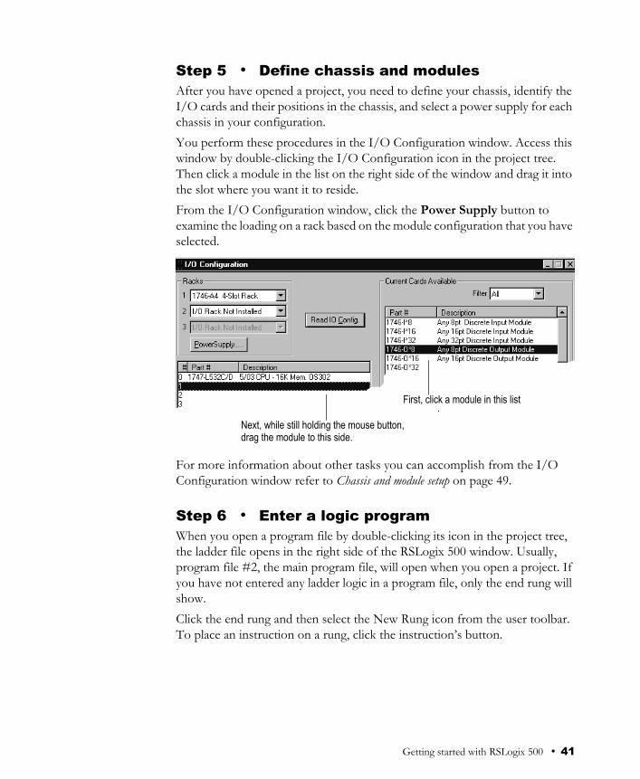
Step 5 • Define chassis and modulesAfter you have opened a project, you need to define your chassis, identify the I/O cards and their positions in the chassis, and select a power supply for each chassis in your configuration. You perform these procedures in the I/O Configuration window. Access this window by double-clicking the I/O Configuration icon in the project tree. Then click a module in the list on the right side of the window and drag it into the slot where you want it to reside.From the I/O Configuration window, click the Power Supply button to examine the loading on a rack based on the module configuration that you have selected.
For more information about other tasks you can accomplish from the I/O Configuration window refer to Chassis and module setup on page 49.
Step 6 • Enter a logic programWhen you open a program file by double-clicking its icon in the project tree, the ladder file opens in the right side of the RSLogix 500 window. Usually, program file #2, the main program file, will open when you open a project. If you have not entered any ladder logic in a program file, only the end rung will show.Click the end rung and then select the New Rung icon from the user toolbar. To place an instruction on a rung, click the instruction’s button.
.First, click a module in this list
Next, while still holding the mouse button,drag the module to this side.
Getting started with RSLogix 500 • 41

You can place several instructions on a rung in sequence by clicking the icons one after another. RSLogix 500 places instructions from left to right.RSLogix 500 supports a file-based editor. This means that you can:
create and/or edit multiple rungs at a timeenter addresses before you actually create data table files for your I/Oenter symbols before you have assigned addresses for them in the databaseenter instructions without having to provide addresses until just before validating the file
To add addresses, click an instruction then type the address in the empty field that appears above the instruction. With RSLogix 500 you can also drag and drop addresses from a data table file onto instructions in your ladder logic.
Remember to use the right mouse button to access functions whenever possible. The right mouse button provides you with context menus that list editing options. And always remember that you can click F1 (or the Help button when available) on any instruction or within any window to access help.Keyboard users can press the [Shift + F10] key combination to access a right mouse menu.
Tip As you begin to enter an address (type file letter), a wizard pops up a list of valid options. You can then make a selection by pressing [Enter] to select the default item, or navigate the list to make a different selection. You can also ignore the list and continue entering your own address. If you want to close the wizard press the [Esc] key. It can be opened again by pressing [Insert] when an address/symbol entry field is open.
This is the “new rung” icon. Click it to place a new rung on your ladder.
Each of these tabs displays a different category of instructions in the toolbar. You can customize the categories.
If there are too manyinstructions on the toolbarto see them all, use these
arrows (right and left) toscroll through the list.
42 • Getting Results with RSLogix 500™

For more detailed information about the steps you follow to enter the ladder logic including information about branching, addressing, and performing program edits online, refer to Entering ladder logic on page 51 in this book.
Step 7 • Add documentation to your logic instructions
You can use several method to add symbols and descriptions to addresses in the database.
Modify symbols and descriptions from within a program file. To do this, right-click the address in the instruction that you want to document, then click Edit Symbol or Edit Description.Modify an address’s assigned documentation in the data file. Double-click the data file in the project tree, and then click on an address within the grid that appears on the data file dialog. At the bottom of the dialog there are fields where you can enter the documentation for the address.Modify the database using the database editor. Double-click an icon in the database folder located in the project tree. Enter a symbol while creating new instructions, then assigning an address to the symbol using the database symbol/description editor. View and edit the project database using Microsoft Excel (RSLogix 500 Professional version only)
For information about the database import and export options available to you refer to Importing or exporting the documentation database on page 63 in this book.
Tip You can select multiple rungs by holding down the [Ctrl] key and clicking the left mouse button on every rung you want to select. You can also select a range of rungs by holding down the [Shift] key and clicking the beginning rung and ending rung.When you select rungs in this manner, RSLogix 500 remembers the order in which you made your selections, and pastes the rungs to the clipboard in that order. When you paste the rungs, the order in which you copied them is retained. For example if you click rung 11 and then [Shift] click rung 8 to copy a range of rungs, the rungs are copied to the clipboard from rung 11 to rung 8. Pasting these rungs will place them in the new location in this same order.
Getting started with RSLogix 500 • 43

Step 8 • Validate your projectBefore you can compile and download your project to a processor, you must validate the project. Validation makes sure your project meets the basic rules of SLC 500 or MicroLogix programming. You can validate a single program file or you can validate your entire project at one time. To verify a file, click the Verify File icon or click Edit > Verify File. To verify your whole project, click the Verify Project icon or click Edit > Verify Project.After you initiate a verification, the Verify Results output window displays and gives you information about mistakes or omissions that may have occurred as you wrote your program logic.
The results of any verification aredisplayed at the bottom of the window under the project tree. To hide this results window after viewing it, click the X in the upper left corner of the window.
Click on any result item to navigate to the location of the error within the logic program.
44 • Getting Results with RSLogix 500™

Step 9 • Configure communication channel, download and go online
Before going online you have to define processor communication settings, such as baud rate, and also decide certain system and protocol controls. Depending on the type of processor that you are using and the method of communication (direct vs. networked or modem), the complexity of this procedure varies.Double-click the channel configuration icon in the project tree to make these settings. If you need information about any parameter, click Help on the channel configuration window.Finally, click Download > Comms to download the current offline program into the controller. RSLogix 500 will ask if you want to go online. Click Yes to go online.
Step 10 • Monitor data filesYou can use RSLogix 500 to monitor what is happening in your data table files.While monitoring these files you can:
define how your data file selection grid will displaychange values in the data tablechange the display radixshow which addresses are used in your ladder logicswitch between filesquickly jump to another address in another data table filecross reference data
To monitor a data table file, click the data file icon that represents the file you want to monitor. You can have multiple data table files opened for monitoring at the same time. Drag each data table window into viewing position by clicking on the title bar and moving the mouse. Release the mouse button to place the data table window.
Tip If you are developing the program offline – for example, if you are using a computer that is not located where you will use the program – you may want to override system communication settings made in step 1of this quick-start guide. You can override the system communication settings this from the Controller Properties window, Controller Communications tab. Settings made through this method will override any driver and node settings established in step 1, and should be completed before proceeding with step 8.
Getting started with RSLogix 500 • 45
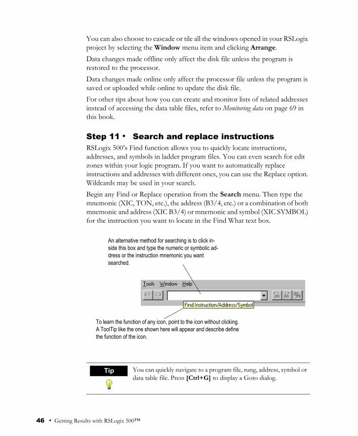
You can also choose to cascade or tile all the windows opened in your RSLogix project by selecting the Window menu item and clicking Arrange.Data changes made offline only affect the disk file unless the program is restored to the processor. Data changes made online only affect the processor file unless the program is saved or uploaded while online to update the disk file. For other tips about how you can create and monitor lists of related addresses instead of accessing the data table files, refer to Monitoring data on page 69 in this book.
Step 11 • Search and replace instructionsRSLogix 500’s Find function allows you to quickly locate instructions, addresses, and symbols in ladder program files. You can even search for edit zones within your logic program. If you want to automatically replace instructions and addresses with different ones, you can use the Replace option. Wildcards may be used in your search.Begin any Find or Replace operation from the Search menu. Then type the mnemonic (XIC, TON, etc.), the address (B3/4, etc.) or a combination of both mnemonic and address (XIC B3/4) or mnemonic and symbol (XIC SYMBOL) for the instruction you want to locate in the Find What text box.
Tip You can quickly navigate to a program file, rung, address, symbol or data table file. Press [Ctrl+G] to display a Goto dialog.
An alternative method for searching is to click in-side this box and type the numeric or symbolic ad-dress or the instruction mnemonic you want searched.
To learn the function of any icon, point to the icon without clicking.A ToolTip like the one shown here will appear and describe definethe function of the icon.
46 • Getting Results with RSLogix 500™
Step 12 • Print a reportYou can obtain a printout of various elements of your project, such as program files, data table files, and processor information. Select your report choices from the File menu by selecting Report Options.
Tip To preview the way a ladder file will print, click Preview. You can scale up the image to make the instructions appear larger on the printed page or scale down the image so that in cases where many instructions are on a rung of logic, all the instructions can fit on the printed page.
Getting started with RSLogix 500 • 47

48 • Getting Results with RSLogix 500™

After you have opened a project, you need to define your chassis, identify the I/O cards and their positions in the chassis, and select a power supply for each chassis in your configuration. You can also display the I/O configuration for your project at any time by double-clicking the I/O Configuration icon in the project tree.
The I/O Configuration dialog lets you do other tasks also.You can learn if the power supply you have planned to use will supply enough power for the modules you have placed in the rack.You can configure your analog and other specialty modules.You can automatically read the existing I/O configuration of a processor node on the network.
Chapter
3 Chassis and module setup
Click this button to call a dialog (shown) allowing you to select a processor from which you want to read the configuration.
Chassis and module setup • 49

Power supply loading
Access the Power Supply Loading dialog by clicking Power Supply on the I/O Configuration dialog. The Power Supply Loading dialog is informational only. You cannot establish any settings on this dialog. Use it to examine the loading on a rack based on the module configuration that you have selected.
Analog and specialty module configurationIf you have a Specialty I/O Module in your configuration, you have to enter additional parameters so that the module can function properly in your program. You enter this information in the Advanced I/O Configuration window. Go to this dialog by clicking the Adv Config button on the I/O Configuration dialog.Remember you can always click the Help button or press [F1] on a dialog if you are unfamiliar with any of the parameters.
Automatic I/O configurationIf you are programming an SLC 5/03™, SLC 5/04™ or SLC 5/05™ processor offline and have communications configured for the processor, you can have the processor read the actual I/O configuration for the processor and reflect that information on the I/O Configuration window. This can save considerable time. To do this, click the Read I/O Config button on the I/O Configuration dialog.
These figures represent the current power supply loading based on your module configuration.
These figures estimate the power available before an overload occurs.
This is where you receive advisory messages about your power supply selection.
50 • Getting Results with RSLogix 500™
This chapter provides information that you can use to make editing your ladder logic easier.
Backing up your workRemember to back up your work as you develop your ladder logic programs. RSLogix 500 uses two types of backup files that you can access at any time, and provides you with an auto-recovery file in the case of a power failure. All of these files contain the entire description database associated with the project.
Auto-Backup files are created automatically each time you save a project. You can preset how many backups should be retained for any project by entering a Number of Backups on the System Preferences tab of the System Options dialog. Reach this tab from the Tools menu. Then click Options and select the System Preference tab. Auto-backup files (saved as .RSS files) have the letters BAK and a series of numbers (000 to 999) appended to the filename. For example, an auto-backup created for project TEST.RSS might be identified as TEST_BAK000.RSS, and a more recent backup might be identified as TEST_BAK001.RSS. Compressed Format Backup files are typically generated for archiving or giving to another user. Compressed format backup files include the .RSS and all database files for the project compressed into a single .RS1 file. From the File menu click Backup Project to generate a compressed-format backup file.
Chapter
4 Entering ladder logic
Tip Shortcut methods exist for most editing functions within RSLogix 500. You can access this list of shortcuts in the online help by searching the word “shortcuts” in the online help.
Entering ladder logic • 51

Crash RecoveryIf you experience a power interruption, RSLogix 500 provides you with a recent backup file containing current edits.RSLogix 500 automatically creates file backups while you are working with a project and when you save the project. This auto-generated recovery file (internal RSS file) is only available to you the next time you open a project if you have a system crash or your power is interrupted. After attempting to open a project after a power failure RSLogix 500 prompts you with choices. You can open:
the auto-saved file, ensuring retention of any edits made before the power interruption.the last backup that you made, when you selected Save before the power interruption.
You can set the interval time at which auto-recovery saves of your project will occur. Do this by making a setting in the Preferences dialog. The auto-recovery process ensures that you will be able to retain any work that had been done on the file between the time of the power interruption and the last manual save.
Tip You must have saved or closed the file you are working on at least one time for the auto-recovery process to work. Therefore, it is good practice to save the file immediately after beginning a new project. This ensures that your auto-recovery process can begin properly.
52 • Getting Results with RSLogix 500™

Quick entry of instructionsTo make your programming tasks faster, RSLogix 500 lets you map any available alphabetic key (A-Z) on your computer keyboard to a ladder logic programming instruction.
From the View menu click Properties. Then click Quick Key Mapping to access the mapping list. Make sure you have a program file window opened and active or you will not be able to select Properties from the View menu.
Tip You can jump to any rung in your project by clicking the Search menu, and then clicking Goto. You can go to a rung in the current program file or you can go to a rung in another program file within the same project.Keyboard users can press the [Ctrl + G] key combination to access the Goto Rung dialog.
Double-click the word Free anywhere in this list.
Then click a mnemonic from the drop down list to assign it to the key-board key and make it a quick key.
Entering ladder logic • 53
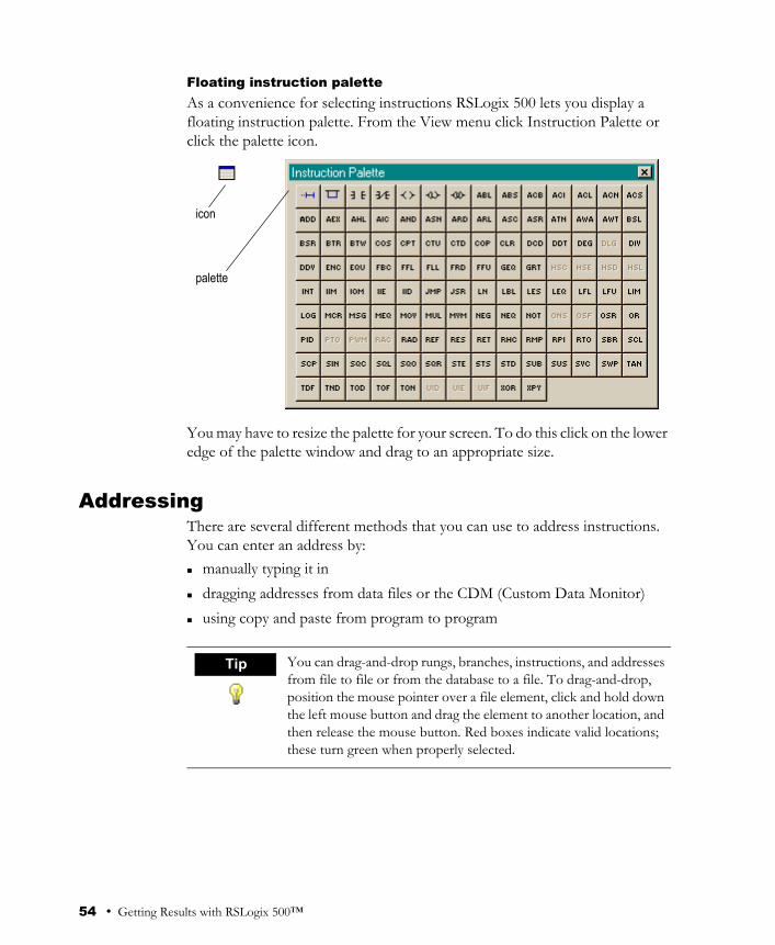
Floating instruction paletteAs a convenience for selecting instructions RSLogix 500 lets you display a floating instruction palette. From the View menu click Instruction Palette or click the palette icon.
You may have to resize the palette for your screen. To do this click on the lower edge of the palette window and drag to an appropriate size.
AddressingThere are several different methods that you can use to address instructions. You can enter an address by:
manually typing it indragging addresses from data files or the CDM (Custom Data Monitor)using copy and paste from program to program
icon
palette
Tip You can drag-and-drop rungs, branches, instructions, and addresses from file to file or from the database to a file. To drag-and-drop, position the mouse pointer over a file element, click and hold down the left mouse button and drag the element to another location, and then release the mouse button. Red boxes indicate valid locations; these turn green when properly selected.
54 • Getting Results with RSLogix 500™

Branching
Add a branch
Move a branch
Expand a branch
Nested branches
Parallel branches
Click this icon on the instruction toolbar to place a branch in your ladder logic. If your cursor is on an instruction, the branch is placed immediately to the right of the instruction. If your cursor is on the rung number, the branch is placed first on the rung.
Click on the upper left corner of a branch to move the entire branch structure to another location in your ladder logic program.
Click the right leg of the branch, then drag the leg to the right or left. Valid release points will be visible on the ladder display.
Place the cursor at the upper left corner of a branch leg, click the right mouse button, and select Append New Branch to place another branch structure within the original branch structure.
Place the cursor at the bottom left corner of a branch leg and click the right mouse button to Extend Branch Leg Up or Extend Branch Leg Down.
Entering ladder logic • 55

Copy branch leg
Copy entire branch structure
Delete a branchPlace the cursor at any location on the branch and click the right mouse button. Then click Delete. If you cut or delete a branch, all instructions on the branch are also deleted.
Branching restrictionsYou are limited to a maximum of 75 parallel branches.You are limited to a maximum of 4 nested branches. (SLC 5/02 and higher and MicroLogix).
Undo operationThe undo icon reverses your last action. You can use this icon to walk through (and undo) your previous actions one at a time. RSLogix 500 remembers up to 200 previous actions.If you want to undo a move operation, you must click undo two times. This is because RSLogix 500 considers a move a series of two actions (copy and cut). You have to let RSLogix know that you want both the copy and the cut undone. If you click undo only one time when trying to undo a move, the move appears to be a copy, and you will see the moved element appear at both locations.
Click on the left edge of the branch leg you want to copy. In the picture at the left this is the center leg. Then click copy in the right mouse menu. Finally click on a rung or instruction in your logic and click paste from the right mouse menu to insert the rung leg
Select the right leg of the branch structure, then click copy in the right mouse menu. Finally click on a rung or instruction in your logic and click paste from the right mouse menu to insert the rung structure.
56 • Getting Results with RSLogix 500™

Online editingThe online editing function lets you monitor and correct your ladder program when your programming terminal is connected to a SLC 5/03, SLC 5/04 or SLC 5/05 processor. Only one programming device at a time can perform online edits of the program.Online editing functions consist of inserting, replacing, and deleting rungs in an existing ladder program while online with the processor. Within your logic program RSLogix 500 places zone markers in the margin to the left of the left rail. These letters signify edit zones and they indicate the type of ladder program edit that exists in the program. Lower case zone markers indicate edits that exist only in the computer memory. Upper case zone markers indicate edits that exist in the processor memory. After successfully assembling the edited rungs, the zone markers disappear.
Tip You can search for zone markers in your project the same way you might search for an instruction or an address. To do this, click the Special button on the Find dialog.
Entering ladder logic • 57

Lower case zone markers
Upper case zone markers
e (Offline and online, all controllers) These rungs are currently under edit within the computer RAM. If you are working offline, after a successful program verification the lower-case e will disappear and the edits will be incorporated into the program. If you are working online, after accepting the rung, the lower-case e will be replaced by an upper-case I indicating that the rung is now in the controller's memory and will be inserted into the program file.
i (Online Editing, SLC 5/03, 5/04 and 5/05 controllers only) These rungs are to be inserted into the program. Rungs marked with a lower-case i currently exist in the computer memory and will not be entered into the controller until the rung is accepted (right mouse button selection). After the rung is accepted, the lower-case i is replaced by an upper-case I.
r (Online Editing, SLC 5/03, 5/04 and 5/05 controllers only) These rungs are to be replaced in the ladder program. Rungs marked with a lower-case r currently exist in the computer memory and will not be entered into the controller until the rung is accepted (right mouse button selection). An r marked rung is always preceded by an e marked rung. After the rung is accepted, the lower-case r will be replaced by an upper-case R.
d (Online Editing, SLC 5/03, 5/04 and 5/05 controllers only) These rungs are to be deleted from the ladder program. Rungs marked with a lower-case d indicate a deletion reflected in the computer memory. This deletion will not be reflected in the controller until the rung is accepted (right mouse button selection), at which time it will be replaced by an upper-case D.
I (Online Editing, SLC 5/03, 5/04 and 5/05 controllers only) These rungs have been inserted in the controller's logic program. You can test the edits by selecting the Edit menu and clicking Test Edits to see how the rung works in the online ladder program. Click Assemble Edits to finalize the rung insertion and complete the editing process.
R (Online Editing, SLC 5/03, 5/04 and 5/05 controllers only) These rungs have been replaced in the controller's logic program. Rungs marked with an upper-case R continue to function in the program until you select Test Edits to see how the new rung works in the online program. Select Assemble Edits to finalize the replacement and complete the editing process.
D (Online Editing, SLC 5/03, 5/04 and 5/05 controllers only) These rungs have been deleted in the controller's logic program. Rungs marked with an upper-case D continue to function in the program until you select Test Edits to see how the program functions without the rungs in the online program. Select Assemble Edits to finalize the deletion and complete the editing process.
58 • Getting Results with RSLogix 500™
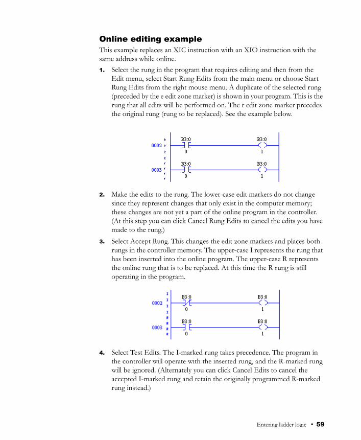
Online editing exampleThis example replaces an XIC instruction with an XIO instruction with the same address while online. 1. Select the rung in the program that requires editing and then from the
Edit menu, select Start Rung Edits from the main menu or choose Start Rung Edits from the right mouse menu. A duplicate of the selected rung (preceded by the e edit zone marker) is shown in your program. This is the rung that all edits will be performed on. The r edit zone marker precedes the original rung (rung to be replaced). See the example below.
2. Make the edits to the rung. The lower-case edit markers do not change since they represent changes that only exist in the computer memory; these changes are not yet a part of the online program in the controller. (At this step you can click Cancel Rung Edits to cancel the edits you have made to the rung.)
3. Select Accept Rung. This changes the edit zone markers and places both rungs in the controller memory. The upper-case I represents the rung that has been inserted into the online program. The upper-case R represents the online rung that is to be replaced. At this time the R rung is still operating in the program.
4. Select Test Edits. The I-marked rung takes precedence. The program in the controller will operate with the inserted rung, and the R-marked rung will be ignored. (Alternately you can click Cancel Edits to cancel the accepted I-marked rung and retain the originally programmed R-marked rung instead.)
Entering ladder logic • 59
5. Select Assemble Edits. All edit zone markers disappear and the edits are incorporated into the online program. There is no Undo option after online edits have been assembled.Going from online to offline with rungs under edit removes the RAM online edits. Make sure you have accepted edits before going offline if you want any changes retained in the processor.
Online editing restrictionsYour programming terminal must be connected to a SLC 5/03, SLC 5/04 or SLC 5/05 processor. During an online editing session you cannot:
resize data table filescreate or delete program files change program file protectionchange index across file boundaries flagreconfigure the I/Oselect force protection
ASCII editingASCII Editing is a function of RSLogix 500 that lets you modify instructions using ASCII instruction mnemonics instead of having to modify instructions using the ladder editor. A quick way to call the ASCII Editor is to double-click a rung number in the left margin. If you double-click a rung with logic already on it, you will see the mnemonics for the existing instructions and can modify or add to them. If you double-click an empty rung, you get an empty editing box into which you can type the mnemonics that represent the logic you want placed on the rung.
Configuring interruptsUse interrupts to interrupt the scan of the main program to accomplish a certain task. Programming requires you to enter essential criteria for the interrupt to function properly. Depending on the processor you are using, this criteria is entered into the Status file by accessing it directly (All SLC processors and MicroLogix 1000 processors) or by entering the appropriate data in the Function File utility (MicroLogix 1200 and 1500 processors only).
Tip Another quick method to call the ASCII text editor is to click the rung number and then press the forward slash key (/) on your keyboard.
60 • Getting Results with RSLogix 500™

Selectable Timed InterruptUse the selectable timed interrupt (STI) function to interrupt the scan of the main program file automatically, on a periodic basis, in order to scan a specified subroutine file. You can specify the time interval when your selectable timed interrupt routine will execute.
Discrete Input InterruptUse the Discrete Input Interrupt (DII) for high-speed processing applications or any application that needs to respond to an event quickly. This function allows the processor to execute a ladder subroutine when the input bit pattern of a discrete I/O card matches a compare value that you programmed.
Processor Type: Action:
All SLC and ML 1000
Select a program file for the STI by double-clicking the S2 data file icon in the project tree. Then click the STI tab and enter the information needed to define the STI. Press the Help button if you need more information.
ML1200 and ML1500
Select a program file for the STI by double-clicking the Function Files icon in the project tree. Then click the STI tab and enter the information needed to define the STI. Press the Help button if you need more information.
Processor Type: Action:
All SLC Double-click the S2 data file icon in the project tree. Then click the DII tab and enter the information needed to define the DII. Press the Help button if you need more information.
ML1000 ML1200 ML1500
Unavailable with these processors.
Entering ladder logic • 61

62 • Getting Results with RSLogix 500™

IntroductionThe import and export utilities are available from the Tools menu by clicking Database. Use the import functionality in RSLogix 500 when you want to apply documentation that already exists to a project you are currently developing in RSLogix 500. Use the export functionality in RSLogix 500 to make the database documentation that is part of your current RSLogix 500 project available to other projects.
Import databaseYou can apply documentation to newly created logic files by importing existing database documentation. The existing documentation might come from:
projects developed using Rockwell Software's DOS-based AI or APS programming softwareanother project developed using RSLogix 500a spreadsheet application, like Microsoft Excel™ (saved as a .CSV file)an ASCII text file
Sometimes when you import a documentation database, there may be conflicting entries in the import file and the database. This is called a collision. Before you begin any import you can select if you want the imported database instance or the current database instance discarded if collisions occur.
Chapter
5 Importing or exporting the documentation database
Tip RSView products can read the documentation database directly from your RSLogix 500 projects – there is no need to export the database when using RSView.
Importing or exporting the documentation database • 63

A.I. project documentation databaseChoose the Native Import option in the Database menu to import database documentation consisting of:
address symbols and descriptions (.DSC files)page title and rung descriptions (.RPD files)
APS project documentation databaseChoose the Native Import option in the Database menu to import database documentation consisting of:
address symbols and descriptions page title and rung descriptions instruction comments
By default the file type selected for import is an .OP$ file. The .OP$ file is the database control file. It references individual database files (for example the symbol/description file or the page title/rung description file) that reside in the same folder as the .OP$ file. After an import completes, RSLogix 500 creates a log file that informs you which database files successfully imported and which database files contained errors and could not successfully be imported.
RSLogix 500 documentation databaseChoose the Native Import option in the Database menu to import database documentation consisting of:
address symbols and descriptions page title and rung descriptions instruction comments symbol groups
By default the file type selected for import is a .CTD file. The .CTD file is the database control file. It references individual database files (for example the symbol/description file or the page title/rung description file) that reside in the same folder as the .CTD file. After an import completes, RSLogix 500 creates a log file that informs you which database files successfully imported and which database files contained errors and could not successfully be imported. For a complete list of RSLogix 500 file extensions for individual database documentation refer to the online help and search “file extensions.”
CSV (Comma Separated Values) fileChoose the ASCII Import option in the Database menu to import database documentation contained in a .CSV file and consisting of:
64 • Getting Results with RSLogix 500™

address symbols and descriptions instruction comments symbol groups
For an example of a .CSV file, refer to the online help and search “CSV format for import/export.”
ASCII delimited text fileYou can import documentation files that were created using RSLogix 500 software or AI software and exported and saved as ASCII delimited files. ASCII delimited means that the fields for each RSLogix 500 database record are enclosed in quote marks and separated by commas. Choose the ASCII Import option in the Database menu to import database documentation contained in an ASCII delimited text file. Choose from:
address symbols and descriptions (.EAS files)page title and rung descriptions (.ERP files)instruction comments (.EIC files)symbol groups (.ESG files)
Users can specify any extension instead of the default extension for each file type (shown above in parenthesis) when using Rockwell Software's AI or RSLogix 500 software.An example of each of the above files can be found in the “ASCII Export” section of this manual.
Export databaseUse the export functionality in RSLogix 500 to make the database documentation that is part of your current RSLogix 500 project available to other projects. You can select the display format for descriptions in the exported file. Choose “treat descriptions as five, 15-character lines of text” if you are exporting a database that will be used by Rockwell Software's AI or APS programming packages.
Importing or exporting the documentation database • 65

You can export documentation to the following output formats:ASCII delimited RS500 formatASCII delimited AI formatASCII delimited APS formata comma separated value file (.CSV file)
After it has been exported, you can edit the ASCII file with a text editor, or load the file into another database.When you export database documentation to AI or APS ASCII delimited format, the symbols, descriptions, and instruction comments may be truncated due to size restrictions imposed by the AI/APS databases. This may result in conflicts in the exported data.
RS500 ASCII delimited text file examplesThe examples in this section show how the documentation would be represented in an exported ASCII text file, using the RS500 output format. Each field in a line of ASCII text is enclosed by quotes and separated by a comma.
Address symbols and descriptions (.EAS files)"B30","0","SYMBOL","description","","","","","0","","","0","GROUP_NAME"
ASCII Field # Maximum Length Contents
1 39 characters Address
2 -- Scope (0=global, 2-255=local program file #)
3 20 characters Symbol
4 20 characters Description line 1
5 20 characters Description line 2
6 20 characters Description line 3
7 20 characters Description line 4
8 20 characters Description line 5
9 12 characters Device code (always 0 for addresses that are not real I/O)
10 9 characters Device description above
11 9 characters Device description below
12 -- Disable xref flag, (0=enabled, 1=disabled)
13 20 characters Symbol group name
66 • Getting Results with RSLogix 500™

Page title and rung descriptions (.ERP files)"RUNG000002-000002","page title","rung comment\"
Instruction comments (.EIC files)"B3/0","XIC","ins comment","","","",""
Symbol groups (.ESG files)"GROUP_NAME","description"
A.I. ASCII delimited text file examplesThese examples show how a line might appear in an ASCII text file exported using the AI output format. Each field in a line of ASCII text is enclosed by quotes and separated by a comma.
Address symbols and descriptions (.EAS files)"B3/0","0","SYMBOL","description","","","","","0","","","0"
The field breakdown of AI ASCII delimited text is the same as shown for RS500 ASCII output format, except the symbol and description fields are limited to 15 characters and there is no symbol group field.
ASCII Field # Maximum Length Contents
1 39 characters Data table address or rung identifier
2 -- Page title
3 20 characters Rung description
ASCII Field # Maximum Length Contents
1 39 characters Address
2 3 characters Instruction type
3 20 characters Comment line 1
4 20 characters Comment line 2
5 20 characters Comment line 3
6 20 characters Comment line 4
7 20 characters Comment line 5
ASCII Field # Maximum Length Contents
1 20 characters Symbol group name
2 80 characters Symbol group description
Importing or exporting the documentation database • 67

Page title and rung descriptions (.ERP files)"RUNG002-0002","page title","rung comment\"
The field breakdown of AI ASCII delimited text is the same as shown for RS500 ASCII output format.
APS ASCII delimited text fileAPS documentation database files saved to ASCII text format contain keywords. Keywords tell the software whether the information immediately following the keyword is a rung comment, an instruction comment, an address comment, or a symbol. Symbol and address comment examples are shown below.SYM B3/0 SYMBOL
AC B3/0 “descriptio”
Refer to your APS programming manual for a complete list of keywords and an explanation of how an APS ASCII text file is built.
CSV formatSearch “CSV format for import/export” in the RSLogix 500 online help for complete details.
68 • Getting Results with RSLogix 500™

IntroductionRSLogix 500 provides you with several customized methods for monitoring data in your data table files.
Multipoint MonitorCustom Data MonitorCustom Graphical Monitor (RSLogix Professional version only)Recipe MonitorHistogramsTrendingData Logging (MicroLogix 1500LRP only)Cross Reference Report
The Multipoint Monitor and Custom Data Monitor methods let you compose lists of addresses that you monitor frequently, or lists of addresses with interrelated functionality, so that you can view, document, protect or even force the changing data values from a single source file.The Custom Graphical Monitor interprets the Custom Data Monitor graphically with easily customized buttons, sliders, gauges and charts.The Recipe Monitor is a variation of the Custom Data Monitor used specifically for monitoring groups of related indirect addresses with a common index. When you are online, you can use histograms and trends to see how your program is behaving over time, by examining bits as the program runs in the SLC controller. A trend logs the data for more than one address (typically related) over a period of time. A histogram logs the data contained in a single address over a period of time.The data logging feature lets you use ladder logic to enable recording data for predefined sets of addresses. Your data can be date and time stamped.The Cross Reference report lists every occurrence of all logical addresses in your project.
Chapter
6 Monitoring data
Monitoring data • 69

Multipoint MonitorThis is only available with MicroLogix 1000, SLC 5/03 - OS302, SLC 5/04 - OS401 and OS410, and SLC 5/05 controllers. The Multipoint Monitor function can only be used to monitor bit addresses. If you want to monitor word addresses as well as bit addresses, use the Custom Data Monitor.Bit addresses in a multipoint list can come from any data table file. They do not have to be from the same data table file.You can use a multipoint list to:
change the on/off state of bitsset and clear forces on I/O pointsdefine separate descriptions for on and off state write protect a bit
To access the Multipoint Monitor feature, double-click the Multipoint Monitor icon located in the project tree.
The offline multipoint list is stored in the project file. It is not part of the processor image. The online multipoint list is stored in the processor memory and is, therefore, cleared whenever the processor memory is cleared. When using the MicroLogix controller, descriptions are always stored in the.RSS file. With the SLC 5/04 and SLC 5/05 controllers the descriptions are stored in the processor.
ForcesTo monitor forces, double-click the input or output force file in the project tree.
You can provide separate descriptions (up to 16 characters) for the on- and off- state of a bit.
Use only bit addresses in a multipoint monitor list.
Caution All force functions can result in sudden machine movement, possibly injuring personnel or causing equipment damage. USE EXTREME CAUTION WHEN USING FORCES!
70 • Getting Results with RSLogix 500™

You can also use the Forces dialog to install and enable or disable forces while you are monitoring your file offline, or in any processor mode while monitoring your file online. Use the right-click menu on a bit in the Forces dialog to force the bit on or off. For more information about forcing, refer to the online help.
Custom Data Monitor (CDM)This is available with all controllers. The Custom Data Monitor function can be used to monitor bit addresses and word addresses. Addresses in a custom data monitor list can come from any data table file. They do not have to be from the same data table file.Features of the custom data monitor include:
CDM lists can contain bit addresses or word addresses.CDM lists can contain ASCII comments to help you clarify bit listings.You can define up to 255 (CDM) lists per project (0-254, inclusive). The CDM name is limited to 20 characters. The CDM description is limited to 59 characters. You can click and drag addresses from the data tables to the CDM file.You can use the [Ctrl] and [Shift] accelerator keys to drag more than one address at a time from the data tables.
To access the Custom Data Monitor feature, double-click the CDM file icon located in the project tree.
Custom Graphical MonitorThis feature is only available in the RSLogix 500 Professional version.The Custom Graphical Monitor provides the data monitoring of a Custom Data Monitor, but in an easy to interpret graphical representation. The Custom Graphical Monitor is a form on which you can place ActiveX controls for buttons, sliders, gauges and charts as well as text and imported images. As is typical of ActiveX controls, you place and configure controls with the form in Design mode and switch to Run mode to activate the controls.
By default an untitled CDM file (#0) is included in yourproject. Rename this file when you add your addresses.
Monitoring data • 71

To access the Custom Graphical Monitor feature, double-click the CGM folder located in the project tree.
Recipe MonitorThe Recipe Monitor is a variation of the Custom Data Monitor. The Recipe Monitor is used specifically for monitoring groups of related indirect addresses with a common index.Many SLC and MicroLogix projects contain data tables in which each element is relevant for a different mode of operation. When these data tables are grouped such that element 1 of each file corresponds to mode 1 of the assembly line used to make product 1, this is referred to as a “recipe.” The easiest way to keep track of recipes is to use a common reference address with indirect addresses to each of the related data files. The Recipe Monitor provides an easy and intuitive interface for this type of application.
To create a new Custom Graphical Monitor file, right-click the Custom Graphical Monitors folder and select New.By default an untitled Custom Graphical Monitor file (#0) is included in your project. Right-click and select Properties to rename this file.
Drag an address from the lad-der or data table to a control.
Click one of these buttons to add text, buttons, sliders, gauges, images, or graphs to the form.
Click here to toggle between Run and Design mode.
Displays the current mode.
Right-click a control and select Properties to change colors, define ranges, and set other options.
72 • Getting Results with RSLogix 500™
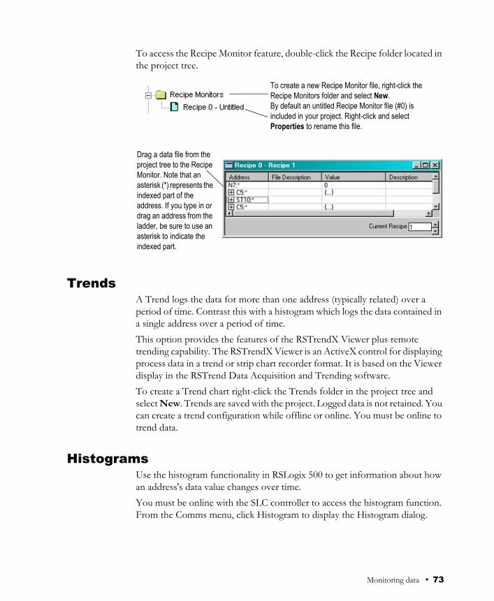
To access the Recipe Monitor feature, double-click the Recipe folder located in the project tree.
TrendsA Trend logs the data for more than one address (typically related) over a period of time. Contrast this with a histogram which logs the data contained in a single address over a period of time.This option provides the features of the RSTrendX Viewer plus remote trending capability. The RSTrendX Viewer is an ActiveX control for displaying process data in a trend or strip chart recorder format. It is based on the Viewer display in the RSTrend Data Acquisition and Trending software. To create a Trend chart right-click the Trends folder in the project tree and select New. Trends are saved with the project. Logged data is not retained. You can create a trend configuration while offline or online. You must be online to trend data.
HistogramsUse the histogram functionality in RSLogix 500 to get information about how an address's data value changes over time. You must be online with the SLC controller to access the histogram function. From the Comms menu, click Histogram to display the Histogram dialog.
To create a new Recipe Monitor file, right-click the Recipe Monitors folder and select New.By default an untitled Recipe Monitor file (#0) is included in your project. Right-click and select Properties to rename this file.
Drag a data file from the project tree to the Recipe Monitor. Note that an asterisk (*) represents the indexed part of theaddress. If you type in or drag an address from the ladder, be sure to use an asterisk to indicate the indexed part.
Monitoring data • 73

By clicking Start on this dialog, the histogram function sends a message to the SLC controller to begin logging data. Each time the address value changes, the controller stores the value for the address in a histogram buffer, logging both the new value and the time interval between value changes. This data is represented in the top portion of the histogram display window.If you frequently log certain data, you can save the configuration and simply load it without having to enter new parameters each time. Use Save and Load (accessible from the right mouse menu) for this functionality.
Data Logging (MicroLogix 1500LRP only)Use the data logging feature to define and edit data sets for later retrieval by a communication device. The data is retentive in the controller through power cycles.
Use this drop-down list box to select a time base for the histogram (in seconds).
If you don’t see data values changing, it is possible that your time base is incorrect for the addresses you are monitoring.
74 • Getting Results with RSLogix 500™

Access data logging from the project tree by clicking the Configuration icon in the Data Logging folder. Then right-click on Data Log Configuration and select New from the context menu
Enable data logging for any queue when the DLG instruction in your ladder logic designating that queue goes from False to True.
Cross ReferenceA Cross Reference report lists all logical addresses in your project and gives the location of every occurrence of each address. The report includes the following data: address, symbol, instruction mnemonic, file # (and name), and rung #. You can sort the Cross Reference report by symbol or by address.As an alternative to a Cross Reference report, you can choose to display cross reference information right on the ladder view. To use this feature, select View > Properties, and click the Address Display tab. Make sure either or both check boxes are checked in the Cross Reference Display area of the dialog.
This is the number of samples that you would like for each record retained. When this limit is reached and a new sample is recorded the oldest record is dumped from the record.
By default the separator character is a space. Although it may look like there is nothing in this box, there is actually a space character.
Type an address here and then click Accept or press [Enter] to place it in the current address list.
Tip You can disable cross references to get online faster. Select Tools > Options. Click the XRef/Address Wizard tab and uncheck the Enable Cross Reference Online box.
Monitoring data • 75

76 • Getting Results with RSLogix 500™
IntroductionSLC library files are ASCII text files of the processor memory that contain the ladder logic, data table file, and force tables. By exporting (saving to file) and importing (loading into a new project) these SLC files, you can reuse existing work. SLC files can be opened in any ASCII text editor and modified for use in your projects.Things to remember about library files
Only verified project data can be saved to an .SLC file.Exported SLC libraries limit symbols to 15 characters. If you have a project file with database symbols that are 20 characters in length, exporting the project to a SLC library will truncate the symbols to 15 characters maximum.Graphics characters are not allowed.The file name of the ASCII file can contain up to eight characters consisting of (A-Z, 0-9, or the underscore character).The file extension of the ASCII processor memory file must be SLC.The text editor you use with an ASCII text file must produce only printable ASCII characters, with no control characters or hidden characters.
Exporting librariesYou can save entire projects or partial libraries. To save a partial library, select the rungs you want to save in the library. If you select no rungs a complete save occurs. Then from the right mouse menu click Copy to SLC Library, and after supplying the path and filename, click Save.
Chapter
7 Saving and loading SLC libraries
Tip You can examine any error messages resulting after an import or export operation by examining the .LOG file. This file is stored in the folder named on the Preferences tab accessed by clicking the Tools menu and selecting Options. You can change this default folder.
Saving and loading SLC libraries • 77

You can place a description in the SLC file by typing the description in the Library Description field. This description appears when you import the library.
Importing librariesTo import a library file, open the project into which you want to load the library. Then from the right mouse menu click Paste from SLC Library.If you are loading a complete program image into an existing project, data table values in the library will overwrite values in the base program, and incoming rungs will be appended to existing program files.
If you choose Partial Save, make sure you selected the rungs before displaying this window.
Checking Annotate Library places additional information in the SLC file about the rungs’ position in the original program. This information is used for troubleshooting a li-brary file, and can help you if you intend to manually edit the .SLC file in a text editor.
78 • Getting Results with RSLogix 500™

If you are loading a partial library, select the rung in your program that you want the library rungs to precede. The library rungs will always be placed before the rung you select. Data table values from the library will overwrite existing data table values for those addresses already present in the base project
Choose the indexed mode and then click the Edit Index button if you want to display a Fixup table from which you can adjust the addresses in the imported library so that there are no conflicts with the addresses in the base program.
If you change base address I:000/0 to I:016/00 (in the Fixup column) and press [Enter], the addresses that are relative to I:000/00 change to follow the change in the base. If there were more addresses relative to base address I:000/0, each one would be offset by the change applied to the octal base address. Relative addresses include all the addresses in the list of the same data file up to the next Base address.
You can change the type address. Double-click and select Base, Relative, or Global from the drop-down listbox. An address set to Global is not affected by indexing to a preceding base address.
Saving and loading SLC libraries • 79

80 • Getting Results with RSLogix 500™

RSLogix 500 comes in two editions: a Standard edition that provides basic ladder logic editing functions, and a Professional edition that provides additional functions to expand your automation solutions and make editing ladder logic simpler. This chapter briefly describes the features included in RSLogix 500 Professional.
Microsoft® Visual Basic for Applications® supportRSLogix 500 Professional allows you to expand your automation solutions through Microsoft Visual Basic for Applications (VBA). VBA allows you add and edit Visual Basic code within the RSLogix 500 development environment. RSLogix 500 Professional includes an object model that you can access through VBA. VBA code created through RSLogix 500 Professional is stored in the .RSP files for your projects.You can run VBA code with RSLogix 500 Standard – to create or edit VBA code you must use RSLogix 500 Professional.See the manual titled RSLogix Automation Interface Reference Manual for more information about using VBA in your automation solutions. This manual is included with RSLogix 500 Professional.
Custom Graphical MonitorThe Custom Graphical Monitor provides graphical data monitoring for your projects. In the Custom Graphical Monitor, you can place graphical buttons, sliders, gauges, charts, text, and imported images. See Custom Graphical Monitor on page 71 for more information about using this feature.
Chapter
8 Features in RSLogix 500 Professional
Features in RSLogix 500 Professional • 81

Editing project databases using Microsoft® Excel®
RSLogix 500 Professional allows you to view and edit project databases with Microsoft Excel software. Microsoft Excel 97 (and later versions) comes with an ActiveX control that RSLogix 500 can use. You must have Microsoft Excel installed on the same computer as RSLogix 500 Professional to use this feature.The Microsoft Excel ActiveX control gives you the powerful editing features of Excel, such as search/replace, and modifying multiple records at the same time. Using this control minimizes or eliminates the need for database import/export operations.To access the Excel editor, click Tools > Database > Edit Using Excel. The Address/Symbol Editor will open using Excel as the editing tool. Pressing [F1] will access the Microsoft Excel Help system. When the Excel editor is displayed and has focus, RSLogix 500 displays the Excel menus and toolbars. You can also access Excel functions by using the right-mouse button menus while working in the editor. Keep the following information in mind when using Excel to edit the database:
When you open the Excel editor, the entire contents of the Address/Symbol database is automatically loaded into the control. Changes made within the Excel editor will not be applied to the Address/Symbol database until you click Apply or OK. When you apply changes, the entire Address/Symbol database will be overwritten with the contents of the Excel editor. Empty rows within the Excel editor are be ignored when applying the contents to the database. If records are added, removed, or moved within the Excel editor, they will be sorted when the contents are applied to the Address/Symbol database. When you click Apply or OK, all legal records will be written to the Address/Symbol database. Illegal records (records containing illegal characters, fields with too many characters, duplicate records, etc.) will not be written to the database. Any errors or illegal records encountered when applying the contents of the Excel editor to the database will be logged and displayed in a separate window. You have the option of saving this information to a file. If you close the Excel editor without clicking Apply or OK (by clicking Cancel), the editor closes without overwriting the database. Changes made in the editor since the last Update Changes operation will be lost.
82 • Getting Results with RSLogix 500™

The Excel editor is limited to approximately 64,000 rows per sheet. Databases with more than 50,000 records will have their contents spanned to multiple Excel sheets. All standard features of the Excel Active X control will be available to manipulate the database. When the Excel editor has focus, these features are accessed through the menus or toolbars or from the right-mouse menu. Remember, you can always get help with the Excel editor by pressing the [F1] key.
Logic TraceThe Logic Trace feature lets you navigate through your ladder logic like using a Web browser. As you move your cursor through a ladder logic project, the Logic Trace feature keeps track of where you have been. You can then use the Logic Trace toolbar to navigate back to previous positions, or from earlier positions to later ones.You can turn the logic trace toolbar on or off by clicking View > Toolbars and selecting or deselecting the Logic Trace toolbar.
How logic trace worksAs you move your cursor through the ladder logic, the software records the positions of your cursor. When no back or forward history is available, the logic trace arrow buttons are disabled (grayed out). Actions that create a “back” navigation history include cross reference navigation, program file display change, clicking your mouse on ladder logic rung/instruction elements, searching ladder logic, using the Goto Rung function, using dot commands, etc. Using the keyboard arrow keys will not generate a navigation history.
Back button Forward button
Back menu Forward menu
Features in RSLogix 500 Professional • 83

Actions that create a “forward” navigation history are limited to clicking an enabled “back” toolbar button or selecting a location from the “back” pull down menu. When you click a “back” button, the cursor will move to the previous location in the navigation history. Once you have moved backward in the navigation history, clicking the “forward” button will move the cursor forward through your navigation history. The pull down menus are limited to a maximum of 10 entries. Each entry lists a rung/instruction location. While the menus are limited to showing a maximum of 10 entries, the arrows allow you to go much farther back.If you delete an instruction or rung that is in the history, that item is removed from the logic trace navigation history. If you edit a rung or instruction that is in the navigation history, it remains in the history.
84 • Getting Results with RSLogix 500™

Rockwell Software’s products are copy-protected. Only a computer with access to the activation key can run the software. The key is located in an activation file, which is originally located on the Master disk supplied with the RSLogix 500 product. The activation file contains one activation key per product. Each key contains one or more licenses depending on how many copies of the product you have purchased.
During the setup process, the setup program gives you the opportunity to move the activation file from the Master disk to the root folder of the drive on which you’re installing the software.
Appendix
A EVMOVE Activation
RSLogix 500 software currently supports both the EVMOVE activation and FactoryTalk Activation systems for activating software. New installations of RSLogix 500 software must use the FactoryTalk Activation system. Older installations of RSLogix 500 that have used the EVMOVE activation system may continue to do so.Rockwell Software advises all RSLogix 500 users to upgrade their activation system to avoid problems with future releases of RSLogix 500.This appendix applies only to the EVMOVE activation system.
Store your Master disk in a safe place. If your activation becomes damaged, the Master disk may be the only means to run your software in an emergency.
Tip
Tip
EVMOVE Activation • 85

When you launch RSLogix 500, the software first checks your local hard drives, then network hard drives, and finally local floppy drives for activation. If the system fails to detect either the activation file or the Master disk, you will receive an error message stating that activation is required to run the RSLogix 500 software.
Protecting your activation files
To avoid damaging your activation files, do not perform the following operations with activation files on the hard drive.
Restore from backupUpgrade the operating systemCompress or uncompress the hard drive
Defragmentation utilities will not harm activation files.Before running any type of utility that may modify the structure or organization of the hard drive, remove activation from the hard drive:1. Use the Move Activation utility (EvMove) to move activation files from
the hard drive to an activation disk.
Run EVMOVE.EXE from your hard drive (located in C:\Program Files\Rockwell Software\RSUtil if you accepted the default folder location during installation).
2. Perform the hard disk operation.
Systems attached to extensive networks can take quite a while to search for activation files on all available drives. You can use the CHECKDRIVES environment variable to specify and/or limit the drives your software checks for activation files and to specify the order in which they are checked. Refer to the activation utilities online help file by selecting Help > Copy Protection.
Tip
Certain anti-virus software packages, such as Norton Anti-virus, can corrupt the activation files. Configure your anti-virus software to avoid checking the files EVRSI.SYS and 386SWAP.PAR.
Caution
Do not use the Move Activation utility if Rockwell Software products are currently running. Ensure all software programs are closed before initiating the EvMove utility.
Caution
86 • Getting Results with RSLogix 500™

3. Move the activation files back to the hard drive.
Activating RSLogix 500Depending on your needs, you can activate RSLogix 500 from any of the following:Hard drive. The activation key resides on your computer’s hard disk. Use this method if you will typically use RSLogix 500 on only one computer. This is the default method if you activate RSLogix 500 during installation. To run RSLogix 500 on a different computer, move the activation key back to the Master disk, and then to the hard drive of the new computer.Diskette drive. The activation key resides on a floppy disk (activation disk). Use this method if you will typically use RSLogix 500 on more than one computer, for example, if you want to run RSLogix 500 on a desktop computer at some times and a portable computer at others.Network drive. The activation keys reside on a network drive. Use this method if you have purchased multiple licenses of the software and want several users to be able to activate the software over a network. Refer to the online help for instructions on moving activation to a network drive (refer to the “Finding more information about activation” section in this chapter to access online help).
Running the activation utilitiesThe utilities for moving and resetting activation are called EvMove and Reset respectively. Reset is used when an activation file has been damaged. The EVMOVE.EXE and RESET.EXE files are located on your hard drive (located in C:\Program Files\Rockwell Software\RSUtil if you accepted the default folder location during installation). To run these programs, select Start > Progams > Rockwell Software > Utilities > Move Activation or Reset Activation.
You must use the move utility, EvMove, to move activation files. Attempts to copy, move or e-mail an activation file by other means will damage the file.
Caution
EVMOVE Activation • 87
Finding more information about activationThe online help (COPYPROT.HLP) provides more extensive information on activation including subjects such as:KEYDISK. Set this environment variable to tell your computer to look for activation on floppy drivesCHECKDRIVES. Specify which drives to search for activationnetwork activation. Move activation to a network server to allow multiple users access to the activationmoving activation. See detailed instructions for moving activationresetting activation. See detailed instructions for using the Reset utility to repair a damaged activation filetroubleshooting. Look up error messages, get problem-solving suggestionsYou can access online help:
from the Help button on one of the EvMove or Reset dialog boxes.from RSLogix 500 by selecting Help > Copy Protection from the main menu.without running either RSLogix 500 or the activation utilities. From the Windows Start menu, select Programs > Rockwell Software > Utilities > Activation Help (if you accepted the default folder location during installation).
Some common questionsFollowing are some common problems that people encounter with activation and their solutions.
My activation files were damaged. What should I do?If you have lost the activation because the activation file is damaged, you need to reset activation. Follow the Reset Codes instructions on the Rockwell Software Technical Support web page, or call the technical support telephone number. The web page and telephone number are both listed on the inside front cover of this guide.If you cannot obtain a reset code immediately, follow these instructions to use the Master disk to activate the software as a temporary solution.To use the Master disk to activate software:1. Set the KEYDISK environment variable to TRUE. (Please refer to the
online help.)
88 • Getting Results with RSLogix 500™

2. Insert your Master disk in the floppy drive.3. Run your software as usual. Your software will find the activation on the
Master disk.
I accidentally deleted the software folder on my hard drive. Do I need to call Rockwell Software for replacement activation files?No. Deleting the program files does not delete your activation. The activation files are not stored in the program folder; they are located in the root folder. Your activation files will not be lost unless you format the hard drive, tamper with hidden files in the root folder, or perform certain other hard drive operations (refer to the “Protecting your activation files” section in this chapter for more information).To get the software running again, simply reinstall the software, but do not move the activation when given the opportunity.
Why can’t I move activation to a new floppy disk on a Windows NT system?It has to do with a disk modification that NT does not allow. If you have access to a Windows 98 machine, you can create a disk that will work under NT. Format a floppy and move any activation file to it under Windows 98. (You can move the activation back off the disk if you want to keep it where it was.) Then take that disk to your Windows NT machine and move the activation to it.
EVMOVE Activation • 89

90 • Getting Results with RSLogix 500™
IntroductionUse this chapter to review the sources of additional information on RSLogix 500 software, including online help, RSLogix 500 training, and technical support. You can find out more information about RSLogix 500 software by consulting:
RSLogix 500 online helpRSLogix 500 trainingTechnical support services
RSLogix 500 online helpRSLogix 500 online help provides general overview information, a description of the fields on every dialog box, and step-by-step procedures for working with all of the features of RSLogix 500. To open online help while running RSLogix 500 you can:
choose Help from the menu on the RSLogix 500 main windowclick the Help button on any RSLogix 500 dialog boxpress F1 on any instruction, dialog box, or window viewexpand the Help folder in the project tree and then double-click on any informative file listed to launch a help file.
Chapter
B Getting the information you need
Getting the information you need • 91

Opening an expandable table of contentsTo open an outline of the entire RSLogix 500 online help system:
click Help on the menu bar and then click Contentsclick the Help folder in the project tree and then double-click Contents
IndexThe index tab provides a list of guide words or subjects just like the index of a book. This is a quick way to find information about a specific topic. Follow the directions on the Index tab.
FindIf you don’t see what you are looking for in the contents or index, you can search the entire help file for all occurrences of a word. follow the directions on the dialog to find a word.The first time you click the find tab you will see a message about building a word list. Follow the directions on the screen. The default selection is generally sufficient. For information refer to Microsoft’s online help (Start > Help).
Double-click any closed book icon to reveal the content.
To collapse theoutline, double-click an open book icon.
To go to a topic double-click a page.
Double-click the procedures book to see a list of tasks you can accomplish usingany function of the software.
92 • Getting Results with RSLogix 500™

Learning RSLogix 500 step-by-step
In Help you will find a Step-by-Step topic that asks what you want to do and lets you select from many of the tasks you might want to perform. To quickly step through the major tasks associated with creating a project, going online, and monitoring data, click on the check boxes. If you want more information about some of the other things that you can do associated with a major task, click the specific procedure.
Click this book icon to get morebackground reference materialassociated with any procedure.
Once you have completed reading the “How To” window, you can selectanother task from this list.
Getting the information you need • 93
Quick tips about Windows operating systems and RSLogix 500
Windows operating systems provide some functionality you may not be familiar with. The RSLogix 500 online help can point out some shortcuts and navigational techniques that can make your work easier. Just select Understanding the Operating Environment from the contents page of the online help.
Keyboard shortcutsA list of hot keys (keyboard shortcuts) that enable you to maneuver the software without a mouse can be found in a help file that you can print out. To access this file, select Help > Using the Keyboard. To print any of the keyboard help topics, just click the Print button at the top of the window.Some of these keyboard shortcuts (sometimes called Ctrl-key accelerators) are standard to the Windows operating system and work across all Windows-based products. Other shortcuts will only work with the RSLogix 5 and 500 products.
User Application helpThe User Application Help feature allows you to add your own reference source (document, web page, etc.) to the RSLogix 500 project. You can use whatever format you want for the source as long as the computer running RSLogix 500 can open and read that source. For example, you could use a Microsoft Word .DOC file, provided that you had Word on your computer. Or you could use an HTML file if you had a browser that could read the file.Your User Application Help file is saved with the project in RSLogix 500. You can specify one User Application Help file per project.To set up your User Application Help file:1. Create the source file for your User Application Help.2. From the project tree in RSLogix 500, right-click User Application Help
(under the Help folder) and select Properties. The User Application Help dialog appears.
3. Enter the path and file name (you can Browse for the file), or the URL for your source file and click OK.
To specify a different source file, go back to the Properties dialog and enter the new path and name.To display the User Application Help file, double-click on User Application Help (under the Help folder in the project tree) or click Help > User Application Help from the main toolbar menu.
94 • Getting Results with RSLogix 500™

Instruction Set helpAll of the instructions available to you in RSLogix 500 have context-sensitive help. You can click an instruction in your ladder logic for help about the parameters required or for information about why you might use one type of instruction instead of another.Each topic in the instruction set online help also gives you information about which processors can use the instruction and an example of the instruction with sample parameters.
RSLogix 500 TrainingRockwell Software offers both classroom and computer-based training for RSLogix 500.
Classroom trainingOne of the best ways to increase your proficiency at using Rockwell Software products is to attend a Rockwell Software training program. Our training programs can help you master the basics and show you how to unleash the full potential of our software.
Getting the information you need • 95
We offer a wide range of training programs, from regularly scheduled classes conducted at Rockwell Software facilities to custom-tailored classes conducted at your enterprise. The size of each class is kept small intentionally to maximize student engagement.For more information about our training programs:
visit our web sit at http://www.software.rockwell.com/training/view the Support and Training help file either from Help on the menu bar or from the Help folder in the project tree.contact the Rockwell software Training Coordinator at 877-724-7864.
Interactive trainingRockwell Software's new RSTrainer 2000 Self-Paced Training programs provide multimedia lessons and interactive practice exercises designed with student objectives in mind. Features include animated graphics, professional audio and content written by Rockwell Training and Tech Support Specialists. Courses are based on the latest shipping release of the software product and include links to the software help files.RSTrainer 2000 for RSLogix 500 contains four lesson modules and over 35 individual multimedia lessons. You’ll learn to install and configure RSLogix 500 and to use it’s powerful features to efficiently develop and maintain ladder logic programs.A demo of the training program is included on the RSLogix 500 CD-ROM. To run the demo, insert the RSLogix 500 CD_ROM into the CD-ROM drive. When the menu appears, select Try RSTrainer 2000 for RSLogix 500.If the CD-ROM does not autorun, open the Start menu and select Run. Type x:\autoplay (where x is your CD-ROM drive), and click OK. Select Try RSTrainer 2000 for RSLogix 500 from the menu.
Technical support servicesIf you cannot find answers to your questions in this publication or in the online help you can call Rockwell Software technical support.Telephone: 440-646-7800
Fax: 440-646-7801
World Wide Web: http://www.software.rockwell.com/support/
Support staff are available Monday through Friday 8 a.m. to 5 p.m. EST, CST, MST, and PST, except during U.S. holidays.
96 • Getting Results with RSLogix 500™

When you callWhen you call you should be at the computer running the Rockwell Software product and be prepared to provide the following information:
product serial number on the Activation disk labels (You can find the serial number online. On the RSLogix 500 menu, click Help, and then click About.)product version numberhardware you are usingMicrosoft Windows operating system and service pack you are usingexact wording of any messages that appear on the screendescription of what happened and what you were doing when the problem occurreddescription of how you tried to solve the problem
Getting the information you need • 97

98 • Getting Results with RSLogix 500™

IndexAabout this book • iiiactions • 20activation • 2, 85
concurrent • 7damaged • 88EVMOVE • 2, 6FactoryTalk Activation • 2FactoryTalk Activation Client • 6file • 85
definition • ivkey • 85moving • 89network • 88node-locked • 7resetting • 88troubleshooting • 88utilities • 87
addressing • 54anti-virus software • 86ASCII editing • 60
Bback up
automatic • 51compressed format • 51definition • iv
branchingadd a branch • 55copy branch leg • 56copy entire branch structure • 56delete a branch • 56expand a branch • 55move a branch • 55nested branches • 55parallel branches • 55restrictions • 56
CCDM • 71
CGM • 71chassis • 49CHECKDRIVES • 86, 88communications driver • 34compare projects • 39compressing the hard drive • 86concurrent activation • 7configure communication channel • 45contents tab in online help • 92conventions used in this book • iiicopy protection, see activationcrash recovery • 52creating
data table files • 40program files • 40project files • 38
cross reference • 75custom data monitor • 71custom graphical monitor • 71, 81
DD in rung margin • 58d in rung margin • 58data logging • 74data table files
contents of • 40creating • 40monitoring • 45
defragmentation utilities • 86deleting the software folder • 89descriptions
adding to project • 43DII • 61disk space required • 2documentation
adding • 43documentation database
editing with Excel • 82export • 65import • 63
Index • 99

download • 45definition • iv
drag-and-drop editing • 31driver • 34
Ee in rung margin • 58editing
ASCII editor • 60database with Excel • 82drag and drop • 31online example • 59online restrictions • 60
entering ladder logic • 51error messages • 86EvMove • 87EVMOVE activation • 2, 6example
custom graphical monitor • 72data logging • 75histogram • 74multipoint monitor • 70online editing • 59recipe monitor • 73
Excelusing to edit project databases • 82
exportA.I. ASCII delimited text file • 67about • 65RS500 ASCII delimited text file • 66
FFactoryTalk Activation • 2FactoryTalk Activation Client • 6FactoryTalk Activation Tool • 7FactoryTalk Activation Wizard • 7FactoryTalk Administration Console • 5FactoryTalk Automation Platform • 4FactoryTalk Directory Configuration Wizard • 6FactoryTalk Local Directory • 6FactoryTalk Network Directory • 6feature summary • 31files
back-up files • 51recovery • 52
find tab in online help • 92
forces • 70functionality summary • 31
Ggetting started • 31go online • 45goto • 46, 53
Hhardware requirements • 1help
about instructions • 95about online help • iii, 91contents • 92find • 92glossary • ivhow to use • 92index • 92training • iv
hiding program files • 39histograms • 73
II in rung margin • 58i in rung margin • 58I/O chassis • 49I/O configuration • 41, 49
automatic • 50I/O modules • 49icon bar • 32import
A.I. database • 64about • 63APS database • 64ASCII delimited text file • 65CSV (Comma Separated Values) file • 64RSLogix 500 database • 64
index tab in online help • 92installing
RSLinx Classic Lite • 3RSLogix 500 • 1, 9Security Server Client • 8
instruction palette • 33example of • 54
instruction toolbar • 33instructions
100 • Getting Results with RSLogix 500™

how to enter • 41quick entry • 53quick key mapping • 53search and replace • 46
interruptsconfiguring • 60DII • 61STI • 61
KKEYDISK • 88
Lladder view • 33library
definition • ivlocal directory • 6logic trace • 83
Mmaster disk • 85menu bar • 32mnemonic
definition • ivmodule selection • 41modules
analog and specialty • 50monitoring data • 45, 69, 81moving activation • 89multiple rungs
selecting • 43multipoint monitor • 70
Nnetwork
activation • 88network directory • 6node-locked activation • 7
Oonline bar • 32online editing
about • 57example • 59restrictions • 60
Ppolicies • 17power supply • 41
loading • 50print a report • 47program files
contents of • 40creating • 40
projectcompare • 39creating • 38definition • ivopening • 38
project tree • 33
Qquick start • 33, 93
RR in rung margin • 58r in rung margin • 58rack selection • 41, 49recipe monitor • 72recovery after power interrupt • 52reports
previewing • 47printing • 47
resetting activation • 88restoring from backup • 86results pane • 33RSAssetSecurity • 4, 6, 9
importing database from Security Server • 15RSLinx Classic
configuring driver • 34version required • 2
RSLinx Classic Liteinstalling • 3
RSWho • 36
Ssearch and replace • 46secured actions • 20security policies • 17Security Server
importing database into RSAssetSecurity • 15Security Server Client
Index • 101

installing • 8SLC libraries
exporting • 77importing • 78
software requirements • 2status bar • 33step-by-step guide • 93steps for getting started • 33STI • 61symbols
adding to project • 43system communications
configuring • 36
Ttoolbars
icon bar • 32instruction bar • 33logic trace • 83menu bar • 32online bar • 32project tree • 33status bar • 33
tracing logic • 83training • ivtroubleshooting • 28
activation • 88
Uuncompressing the hard drive • 86undo • 56upgrading the operating system • 86upload
definition • iv
VVBA • 81verification
definition • ivresults • 44
Visual Basic for Applications support • 81
WWindows 98 • 89Windows NT • 89
Zzone
definition • ivzone marker
D • 58d • 58e • 58I • 58i • 58R • 58r • 58
102 • Getting Results with RSLogix 500™