r&s fsv-k10x (lte uplink) lte uplink …...r&s®fsv-k10x (lte uplink) preface user manual...
TRANSCRIPT

R&S®FSV-K10x (LTE Uplink)LTE Uplink Measurement ApplicationUser Manual
User
Man
ual
Versi
on 06
1176767802(;ÚÚÜ2)
This manual describes the following firmware applications:
● R&S®FSV-K101 EUTRA / LTE FDD Uplink Measurement Application (1310.9100.02)
● R&S®FSV-K105 EUTRA / LTE TDD Uplink Measurement Application (1310.9780.02)
This manual describes the following R&S FSVA/FSV models with firmware version 3.30 and higher:● R&S®FSVA4 (1321.3008K05)
● R&S®FSVA7 (1321.3008K08)
● R&S®FSVA13 (1321.3008K14)
● R&S®FSVA30 (1321.3008K31)
● R&S®FSVA40 (1321.3008K41)
● R&S®FSV4 (1321.3008K04)
● R&S®FSV7 (1321.3008K07)
● R&S®FSV13 (1321.3008K13)
● R&S®FSV30 (1321.3008K30)
● R&S®FSV40 (1321.3008K39/1321.3008K40)
It also applies to the following R&S®FSV models. However, note the differences described in Chapter 1.4,"Notes for Users of R&S FSV 1307.9002Kxx Models", on page 13.● R&S®FSV3 (1307.9002K03)
● R&S®FSV7 (1307.9002K07)
● R&S®FSV13 (1307.9002K13)
● R&S®FSV30 (1307.9002K30)
● R&S®FSV40 (1307.9002K39/1307.9002K40)
© 2019 Rohde & Schwarz GmbH & Co. KGMühldorfstr. 15, 81671 München, GermanyPhone: +49 89 41 29 - 0Fax: +49 89 41 29 12 164Email: [email protected]: www.rohde-schwarz.comSubject to change – Data without tolerance limits is not binding.R&S® is a registered trademark of Rohde & Schwarz GmbH & Co. KG.Trade names are trademarks of the owners.
1176.7678.02 | Version 06 | R&S®FSV-K10x (LTE Uplink)
The following abbreviations are used throughout this manual: R&S®FSV/FSVA is abbreviated as R&S FSV/FSVA.

ContentsR&S®FSV-K10x (LTE Uplink)
3User Manual 1176.7678.02 ─ 06
Contents1 Preface.................................................................................................... 9
1.1 Documentation Overview............................................................................................. 9
1.1.1 Quick Start Guide............................................................................................................9
1.1.2 Operating Manuals and Help.......................................................................................... 9
1.1.3 Service Manual............................................................................................................... 9
1.1.4 Instrument Security Procedures....................................................................................10
1.1.5 Basic Safety Instructions...............................................................................................10
1.1.6 Data Sheets and Brochures.......................................................................................... 10
1.1.7 Release Notes and Open Source Acknowledgment (OSA).......................................... 10
1.1.8 Application Notes, Application Cards, White Papers, etc..............................................10
1.2 Conventions Used in the Documentation.................................................................10
1.2.1 Typographical Conventions...........................................................................................10
1.2.2 Conventions for Procedure Descriptions.......................................................................11
1.2.3 Notes on Screenshots................................................................................................... 11
1.3 How to Use the Help System......................................................................................11
1.4 Notes for Users of R&S FSV 1307.9002Kxx Models................................................ 13
2 Introduction.......................................................................................... 142.1 Requirements for UMTS Long-Term Evolution........................................................ 14
2.2 Long-Term Evolution Uplink Transmission Scheme............................................... 16
2.2.1 SC-FDMA......................................................................................................................16
2.2.2 SC-FDMA Parameterization..........................................................................................17
2.2.3 Uplink Data Transmission............................................................................................. 17
2.2.4 Uplink Reference Signal Structure................................................................................ 18
2.2.5 Uplink Physical Layer Procedures................................................................................ 18
2.3 References...................................................................................................................20
3 Welcome............................................................................................... 213.1 Installing the Software................................................................................................21
3.2 Application Overview..................................................................................................21
3.3 Support........................................................................................................................ 23
4 Measurement Basics........................................................................... 24
ContentsR&S®FSV-K10x (LTE Uplink)
4User Manual 1176.7678.02 ─ 06
4.1 Symbols and Variables............................................................................................... 24
4.2 Overview...................................................................................................................... 25
4.3 The LTE Uplink Analysis Measurement Application................................................25
4.3.1 Synchronization.............................................................................................................26
4.3.2 Analysis.........................................................................................................................27
4.4 SRS EVM Calculation..................................................................................................29
5 Measurements and Result Displays...................................................315.1 Numerical Results.......................................................................................................31
5.2 Measuring the Power Over Time................................................................................34
5.3 Measuring the Error Vector Magnitude (EVM)..........................................................36
5.4 Measuring the Spectrum............................................................................................ 38
5.4.1 Frequency Sweep Measurements................................................................................ 38
5.4.2 I/Q Measurements.........................................................................................................42
5.5 Measuring the Symbol Constellation........................................................................ 44
5.6 Measuring Statistics................................................................................................... 45
5.7 3GPP Test Scenarios.................................................................................................. 48
6 Configuring and Performing the Measurement.................................496.1 Performing Measurements.........................................................................................49
6.2 Defining General Measurement Characteristics...................................................... 50
6.2.1 Defining Signal Characteristics..................................................................................... 50
6.2.2 Configuring the Input Level........................................................................................... 52
6.2.3 Configuring the Data Capture....................................................................................... 54
6.2.4 Triggering Measurements............................................................................................. 55
6.3 Configuring Spectrum Measurements...................................................................... 57
6.3.1 General ACLR and SEM Configuration.........................................................................57
6.3.2 Configuring SEM Measurements.................................................................................. 58
6.3.3 Configuring ACLR Measurements................................................................................ 59
6.4 Defining Advanced Measurement Characteristics.................................................. 60
6.4.1 Controlling I/Q Data.......................................................................................................60
6.4.2 Controlling the Input...................................................................................................... 61
6.4.3 Configuring the Digital I/Q Input.................................................................................... 62
6.5 Configuring the Signal Demodulation.......................................................................63
6.5.1 Configuring the Data Analysis.......................................................................................63

ContentsR&S®FSV-K10x (LTE Uplink)
5User Manual 1176.7678.02 ─ 06
6.5.2 Compensating Measurement Errors............................................................................. 65
6.6 Configuring Uplink Frames........................................................................................ 66
6.6.1 Configuring TDD Signals...............................................................................................66
6.6.2 Configuring the Physical Layer Cell Identity..................................................................68
6.6.3 Subframe Configuration................................................................................................ 69
6.7 Defining Advanced Signal Characteristics...............................................................71
6.7.1 Configuring the Demodulation Reference Signal.......................................................... 71
6.7.2 Configuring the Sounding Reference Signal................................................................. 73
6.7.3 Defining the PUSCH Structure......................................................................................76
6.7.4 Defining the PUCCH Structure......................................................................................77
6.7.5 Defining Global Signal Characteristics..........................................................................79
6.8 Defining the PRACH Structure...................................................................................79
7 Analysis................................................................................................ 827.1 Signal Part Selection.................................................................................................. 82
7.2 Measurement Units..................................................................................................... 84
7.3 Miscellaneous Analysis..............................................................................................84
7.4 Constellation Diagram Filter...................................................................................... 85
7.5 Y-Axis Scale.................................................................................................................85
7.6 Markers........................................................................................................................ 86
8 File Management..................................................................................898.1 File Manager................................................................................................................ 89
8.2 SAVE/RECALL Key......................................................................................................90
9 Remote Commands............................................................................. 919.1 Common Suffixes........................................................................................................91
9.2 Introduction................................................................................................................. 92
9.2.1 Conventions used in Descriptions.................................................................................92
9.2.2 Long and Short Form.................................................................................................... 93
9.2.3 Numeric Suffixes........................................................................................................... 93
9.2.4 Optional Keywords........................................................................................................ 93
9.2.5 Alternative Keywords.................................................................................................... 94
9.2.6 SCPI Parameters.......................................................................................................... 94
9.3 General Configuration................................................................................................ 96
ContentsR&S®FSV-K10x (LTE Uplink)
6User Manual 1176.7678.02 ─ 06
9.4 Measurement Control................................................................................................. 99
9.5 Numeric Result Query.............................................................................................. 100
9.6 Measurement Result Query......................................................................................110
9.6.1 Using the TRACe[:DATA] Command...........................................................................110
9.6.2 Reading Results..........................................................................................................120
9.7 General Settings........................................................................................................123
9.7.1 Defining Signal Characteristics................................................................................... 123
9.7.2 Configuring the Input Level......................................................................................... 125
9.7.3 Configuring the Data Capture..................................................................................... 128
9.8 Advanced Settings....................................................................................................129
9.8.1 Controlling I/Q Data.....................................................................................................130
9.8.2 Controlling the Input.................................................................................................... 130
9.8.3 Configuring the Digital I/Q Input.................................................................................. 131
9.9 Trigger Configuration............................................................................................... 132
9.10 Spectrum Measurements......................................................................................... 135
9.11 Signal Demodulation................................................................................................ 139
9.11.1 Configuring the Data Analysis.....................................................................................139
9.11.2 Compensating Measurement Errors........................................................................... 142
9.12 Frame Configuration.................................................................................................142
9.12.1 Configuring TDD Signals.............................................................................................142
9.12.2 Configuring the Physical Layer Cell Identity................................................................143
9.12.3 Configuring Subframes............................................................................................... 145
9.13 Advanced Signal Characteristics............................................................................ 147
9.13.1 Configuring the Demodulation Reference Signal........................................................ 147
9.13.2 Configuring the Sounding Reference Signal............................................................... 149
9.13.3 Defining the PUSCH Structure....................................................................................152
9.13.4 Defining the PUCCH Structure....................................................................................154
9.13.5 Defining Global Signal Characteristics........................................................................156
9.14 PRACH Structure...................................................................................................... 156
9.15 Measurement Result Analysis................................................................................. 159
9.15.1 Selecting Displayed Data............................................................................................ 159
9.15.2 Selecting Units............................................................................................................ 162
9.15.3 Using Markers............................................................................................................. 163

ContentsR&S®FSV-K10x (LTE Uplink)
7User Manual 1176.7678.02 ─ 06
9.15.4 Using Delta Markers....................................................................................................166
9.15.5 Scaling the Vertical Diagram Axis............................................................................... 168
List of Commands..............................................................................170
Index....................................................................................................174

ContentsR&S®FSV-K10x (LTE Uplink)
8User Manual 1176.7678.02 ─ 06

PrefaceR&S®FSV-K10x (LTE Uplink)
9User Manual 1176.7678.02 ─ 06
1 Preface
1.1 Documentation Overview
This section provides an overview of the R&S FSVA/FSV user documentation. Unlessspecified otherwise, you find the documents on the R&S FSVA/FSV product page at:
www.rohde-schwarz.com/manual/FSVA
1.1.1 Quick Start Guide
Introduces the R&S FSVA/FSV and describes how to set up and start working with theproduct. Includes basic operations, typical measurement examples, and general infor-mation, e.g. safety instructions, etc. A printed version is delivered with the instrument.A PDF version is available for download on the Internet.
1.1.2 Operating Manuals and Help
Separate operating manuals are provided for the base unit and the firmware applica-tions:● Base unit manual
Contains the description of all instrument modes and functions. It also provides anintroduction to remote control, a complete description of the remote control com-mands with programming examples, and information on maintenance, instrumentinterfaces and error messages. Includes the contents of the getting started manual.
● Firmware application manualContains the description of the specific functions of a firmware application. Basicinformation on operating the R&S FSVA/FSV is not included.
The contents of the operating manuals are available as help in the R&S FSVA/FSV.The help offers quick, context-sensitive access to the complete information for thebase unit and the firmware applications.
All operating manuals are also available for download or for immediate display on theInternet.
1.1.3 Service Manual
Describes the performance test for checking the rated specifications, module replace-ment and repair, firmware update, troubleshooting and fault elimination, and containsmechanical drawings and spare part lists.
The service manual is available for registered users on the global Rohde & Schwarzinformation system (GLORIS, https://gloris.rohde-schwarz.com).
Documentation Overview

PrefaceR&S®FSV-K10x (LTE Uplink)
10User Manual 1176.7678.02 ─ 06
1.1.4 Instrument Security Procedures
Deals with security issues when working with the R&S FSVA/FSV in secure areas. It isavailable for download on the Internet.
1.1.5 Basic Safety Instructions
Contains safety instructions, operating conditions and further important information.The printed document is delivered with the instrument.
1.1.6 Data Sheets and Brochures
The data sheet contains the technical specifications of the R&S FSVA/FSV. It also liststhe firmware applications and their order numbers, and optional accessories.
The brochure provides an overview of the instrument and deals with the specific char-acteristics.
See www.rohde-schwarz.com/brochure-datasheet/FSV
1.1.7 Release Notes and Open Source Acknowledgment (OSA)
The release notes list new features, improvements and known issues of the currentfirmware version, and describe the firmware installation.
The open source acknowledgment document provides verbatim license texts of theused open source software.
See www.rohde-schwarz.com/firmware/FSV
1.1.8 Application Notes, Application Cards, White Papers, etc.
These documents deal with special applications or background information on particu-lar topics.
See www.rohde-schwarz.com/application/FSV
1.2 Conventions Used in the Documentation
1.2.1 Typographical Conventions
The following text markers are used throughout this documentation:
Conventions Used in the Documentation

PrefaceR&S®FSV-K10x (LTE Uplink)
11User Manual 1176.7678.02 ─ 06
Convention Description
"Graphical user interface ele-ments"
All names of graphical user interface elements on the screen, such asdialog boxes, menus, options, buttons, and softkeys are enclosed byquotation marks.
[Keys] Key and knob names are enclosed by square brackets.
Filenames, commands,program code
Filenames, commands, coding samples and screen output are distin-guished by their font.
Input Input to be entered by the user is displayed in italics.
Links Links that you can click are displayed in blue font.
"References" References to other parts of the documentation are enclosed by quota-tion marks.
1.2.2 Conventions for Procedure Descriptions
When operating the instrument, several alternative methods may be available to per-form the same task. In this case, the procedure using the touchscreen is described.Any elements that can be activated by touching can also be clicked using an addition-ally connected mouse. The alternative procedure using the keys on the instrument orthe on-screen keyboard is only described if it deviates from the standard operating pro-cedures.
The term "select" may refer to any of the described methods, i.e. using a finger on thetouchscreen, a mouse pointer in the display, or a key on the instrument or on a key-board.
1.2.3 Notes on Screenshots
When describing the functions of the product, we use sample screenshots. Thesescreenshots are meant to illustrate as many as possible of the provided functions andpossible interdependencies between parameters. The shown values may not representrealistic usage scenarios.
The screenshots usually show a fully equipped product, that is: with all options instal-led. Thus, some functions shown in the screenshots may not be available in your par-ticular product configuration.
1.3 How to Use the Help System
Calling context-sensitive and general help
► To display the general help dialog box, press the [HELP] key on the front panel.
The help dialog box "View" tab is displayed. A topic containing information aboutthe current menu or the currently opened dialog box and its function is displayed.
How to Use the Help System

PrefaceR&S®FSV-K10x (LTE Uplink)
12User Manual 1176.7678.02 ─ 06
For standard Windows dialog boxes (e.g. File Properties, Print dialog etc.), no context-sensitive help is available.
► If the help is already displayed, press the softkey for which you want to displayhelp.
A topic containing information about the softkey and its function is displayed.
If a softkey opens a submenu and you press the softkey a second time, the submenuof the softkey is displayed.
Contents of the help dialog box
The help dialog box contains four tabs:
● "Contents" - contains a table of help contents● "View" - contains a specific help topic● "Index" - contains index entries to search for help topics● "Zoom" - contains zoom functions for the help display
To change between these tabs, press the tab on the touchscreen.
Navigating in the table of contents
● To move through the displayed contents entries, use the [UP ARROW] and [DOWNARROW] keys. Entries that contain further entries are marked with a plus sign.
● To display a help topic, press the [ENTER] key. The "View" tab with the corre-sponding help topic is displayed.
● To change to the next tab, press the tab on the touchscreen.
Navigating in the help topics
● To scroll through a page, use the rotary knob or the [UP ARROW] and [DOWNARROW] keys.
● To jump to the linked topic, press the link text on the touchscreen.
Searching for a topic
1. Change to the "Index" tab.
2. Enter the first characters of the topic you are interested in. The entries starting withthese characters are displayed.
3. Change the focus by pressing the [ENTER] key.
4. Select the suitable keyword by using the [UP ARROW] or [DOWN ARROW] keysor the rotary knob.
5. Press the [ENTER] key to display the help topic.
The "View" tab with the corresponding help topic is displayed.
How to Use the Help System

PrefaceR&S®FSV-K10x (LTE Uplink)
13User Manual 1176.7678.02 ─ 06
Changing the zoom
1. Change to the "Zoom" tab.
2. Set the zoom using the rotary knob. Four settings are available: 1-4. The smallestsize is selected by number 1, the largest size is selected by number 4.
Closing the help window
► Press the [ESC] key or a function key on the front panel.
1.4 Notes for Users of R&S FSV 1307.9002Kxx Models
Users of R&S FSV 1307.9002Kxx models should consider the following differences tothe description of the newer R&S FSVA/FSV 1321.3008Kxx models:● Functions that are based on the Windows 10 operating system (e.g. printing or set-
ting up networks) may have a slightly different appearance or require different set-tings on the Windows XP based models. For such functions, refer to the Windowsdocumentation or the documentation originally provided with the R&S FSV instru-ment.
● The R&S FSV 1307.9002K03 model is restricted to a maximum frequency of3 GHz, whereas the R&S FSVA/FSV1321.3008K04 model has a maximum fre-quency of 4 GHz.
● The bandwidth extension option R&S FSV-B160 (1311.2015.xx) is not available forthe R&S FSV 1307.9002Kxx models. The maximum usable I/Q analysis bandwidthfor these models is 28 MHz, or with option R&S FSV-B70, 40 MHz.
Notes for Users of R&S FSV 1307.9002Kxx Models

IntroductionR&S®FSV-K10x (LTE Uplink)
14User Manual 1176.7678.02 ─ 06
2 IntroductionCurrently, UMTS networks worldwide are being upgraded to high speed downlinkpacket access (HSDPA) in order to increase data rate and capacity for downlink packetdata. In the next step, high speed uplink packet access (HSUPA) will boost uplink per-formance in UMTS networks. While HSDPA was introduced as a 3GPP Release 5 fea-ture, HSUPA is an important feature of 3GPP Release 6. The combination of HSDPAand HSUPA is often referred to as HSPA.
However, even with the introduction of HSPA, the evolution of UMTS has not reachedits end. HSPA+ will bring significant enhancements in 3GPP Release 7. The objectiveis to enhance the performance of HSPA-based radio networks in terms of spectrumefficiency, peak data rate and latency, and to exploit the full potential of WCDMAbased5 MHz operation. Important features of HSPA+ are downlink multiple input multiple out-put (MIMO), higher order modulation for uplink and downlink, improvements of layer 2protocols, and continuous packet connectivity.
In order to ensure the competitiveness of UMTS for the next 10 years and beyond,concepts for UMTS long term evolution (LTE) have been investigated. The objective isa high-data-rate, low-latency and packet-optimized radio access technology. Therefore,a study item was launched in 3GPP Release 7 on evolved UMTS terrestrial radioaccess (EUTRA) and evolved UMTS terrestrial radio access network (EUTRAN). LTE/EUTRA will then form part of 3GPP Release 8 core specifications.
This introduction focuses on LTE/EUTRA technology. In the following, the terms LTE orEUTRA are used interchangeably.
In the context of the LTE study item, 3GPP work first focused on the definition ofrequirements, e.g. targets for data rate, capacity, spectrum efficiency, and latency. Alsocommercial aspects such as costs for installing and operating the network were con-sidered. Based on these requirements, technical concepts for the air interface trans-mission schemes and protocols were studied. Notably, LTE uses new multiple accessschemes on the air interface: orthogonal frequency division multiple access (OFDMA)in downlink and single carrier frequency division multiple access (SC-FDMA) in uplink.Furthermore, MIMO antenna schemes form an essential part of LTE. In an attempt tosimplify protocol architecture, LTE brings some major changes to the existing UMTSprotocol concepts. Impact on the overall network architecture including the core net-work is being investigated in the context of 3GPP system architecture evolution (SAE).
● Requirements for UMTS Long-Term Evolution....................................................... 14● Long-Term Evolution Uplink Transmission Scheme................................................16● References..............................................................................................................20
2.1 Requirements for UMTS Long-Term Evolution
LTE is focusing on optimum support of packet switched (PS) services. Main require-ments for the design of an LTE system are documented in 3GPP TR 25.913 [1] andcan be summarized as follows:
Requirements for UMTS Long-Term Evolution

IntroductionR&S®FSV-K10x (LTE Uplink)
15User Manual 1176.7678.02 ─ 06
● Data Rate: Peak data rates target 100 Mbps (downlink) and 50 Mbps (uplink) for20 MHz spectrum allocation, assuming two receive antennas and one transmitantenna are at the terminal.
● Throughput: The target for downlink average user throughput per MHz is three tofour times better than Release 6. The target for uplink average user throughput perMHz is two to three times better than Release 6.
● Spectrum efficiency: The downlink target is three to four times better than Release6. The uplink target is two to three times better than Release 6.
● Latency: The one-way transit time between a packet being available at the IP layerin either the UE or radio access network and the availability of this packet at IPlayer in the radio access network/UE shall be less than 5 ms. Also C-plane latencyshall be reduced, e.g. to allow fast transition times of less than 100 ms fromcamped state to active state.
● Bandwidth: Scaleable bandwidths of 5 MHz, 10 MHz, 15 MHz, and 20 MHz shallbe supported. Also bandwidths smaller than 5 MHz shall be supported for moreflexibility.
● Interworking: Interworking with existing UTRAN/GERAN systems and non-3GPPsystems shall be ensured. Multimode terminals shall support handover to and fromUTRAN and GERAN as well as inter-RAT measurements. Interruption time forhandover between EUTRAN and UTRAN/GERAN shall be less than 300 ms forrealtime services and less than 500 ms for non-realtime services.
● Multimedia broadcast multicast services (MBMS): MBMS shall be further enhancedand is then referred to as E-MBMS.
● Costs: Reduced CAPEX and OPEX including backhaul shall be achieved. Costef-fective migration from Release 6 UTRA radio interface and architecture shall bepossible. Reasonable system and terminal complexity, cost, and power consump-tion shall be ensured. All the interfaces specified shall be open for multivendorequipment interoperability.
● Mobility: The system should be optimized for low mobile speed (0 to 15 km/h), buthigher mobile speeds shall be supported as well, including high speed train envi-ronment as a special case.
● Spectrum allocation: Operation in paired (frequency division duplex / FDD mode)and unpaired spectrum (time division duplex / TDD mode) is possible.
● Co-existence: Co-existence in the same geographical area and co-location withGERAN/UTRAN shall be ensured. Also, co-existence between operators in adja-cent bands as well as cross-border co-existence is a requirement.
● Quality of Service: End-to-end quality of service (QoS) shall be supported. VoIPshould be supported with at least as good radio and backhaul efficiency andlatency as voice traffic over the UMTS circuit switched networks.
● Network synchronization: Time synchronization of different network sites shall notbe mandated.
Requirements for UMTS Long-Term Evolution

IntroductionR&S®FSV-K10x (LTE Uplink)
16User Manual 1176.7678.02 ─ 06
2.2 Long-Term Evolution Uplink Transmission Scheme
2.2.1 SC-FDMA
During the study item phase of LTE, alternatives for the optimum uplink transmissionscheme were investigated. While OFDMA is seen optimum to fulfil the LTE require-ments in downlink, OFDMA properties are less favourable for the uplink. This is mainlydue to weaker peak-to-average power ratio (PAPR) properties of an OFDMA signal,resulting in worse uplink coverage.
Thus, the LTE uplink transmission scheme for FDD and TDD mode is based onSCFDMA with a cyclic prefix. SC-FDMA signals have better PAPR properties com-pared to an OFDMA signal. This was one of the main reasons for selecting SC-FDMAas LTE uplink access scheme. The PAPR characteristics are important for cost-effec-tive design of UE power amplifiers. Still, SC-FDMA signal processing has some similar-ities with OFDMA signal processing, so parameterization of downlink and uplink can beharmonized.
There are different possibilities how to generate an SC-FDMA signal. DFT-spread-OFDM (DFT-s-OFDM) has been selected for EUTRA. The principle is illustrated in Fig-ure 2-1.
For DFT-s-OFDM, a size-M DFT is first applied to a block of M modulation symbols.QPSK, 16QAM and 64 QAM are used as uplink EUTRA modulation schemes, the lat-ter being optional for the UE. The DFT transforms the modulation symbols into the fre-quency domain. The result is mapped onto the available sub-carriers. In EUTRAuplink, only localized transmission on consecutive sub-carriers is allowed. An N pointIFFT where N>M is then performed as in OFDM, followed by addition of the cyclic pre-fix and parallel to serial conversion.
Figure 2-1: Block Diagram of DFT-s-OFDM (Localized Transmission)
Long-Term Evolution Uplink Transmission Scheme

IntroductionR&S®FSV-K10x (LTE Uplink)
17User Manual 1176.7678.02 ─ 06
The DFT processing is therefore the fundamental difference between SC-FDMA andOFDMA signal generation. This is indicated by the term DFT-spread-OFDM. In anSCFDMA signal, each sub-carrier used for transmission contains information of alltransmitted modulation symbols, since the input data stream has been spread by theDFT transform over the available sub-carriers. In contrast to this, each sub-carrier ofan OFDMA signal only carries information related to specific modulation symbols.
2.2.2 SC-FDMA Parameterization
The EUTRA uplink structure is similar to the downlink. An uplink radio frame consistsof 20 slots of 0.5 ms each, and 1 subframe consists of 2 slots. The slot structure isshown in Figure 2-2.
Each slot carries SC-FDMA symbols, where = 7 for the normal cyclic prefix and = 6 for the extended cyclic prefix. SC-FDMA symbol number 3 (i.e. the 4th symbol
in a slot) carries the reference signal for channel demodulation.
Figure 2-2: Uplink Slot Structure
Also for the uplink, a bandwidth agnostic layer 1 specification has been selected. Thetable below shows the configuration parameters in an overview table.
2.2.3 Uplink Data Transmission
In uplink, data is allocated in multiples of one resource block. Uplink resource blocksize in the frequency domain is 12 sub-carriers, i.e. the same as in downlink. However,not all integer multiples are allowed in order to simplify the DFT design in uplink signalprocessing. Only factors 2, 3, and 5 are allowed.
The uplink transmission time interval (TTI) is 1 ms (same as downlink).
Long-Term Evolution Uplink Transmission Scheme

IntroductionR&S®FSV-K10x (LTE Uplink)
18User Manual 1176.7678.02 ─ 06
User data is carried on the Physical Uplink Shared Channel (PUSCH) that is deter-mined by the transmission bandwidth NTx and the frequency hopping pattern k0.
The Physical Uplink Control Channel (PUCCH) carries uplink control information, e.g.CQI reports and ACK/NACK information related to data packets received in the down-link. The PUCCH is transmitted on a reserved frequency region in the uplink.
2.2.4 Uplink Reference Signal Structure
Uplink reference signals are used for two different purposes: on the one hand, they areused for channel estimation in the eNodeB receiver in order to demodulate control anddata channels. On the other hand, the reference signals provide channel quality infor-mation as a basis for scheduling decisions in the base station. The latter purpose isalso called channel sounding.
The uplink reference signals are based on CAZAC (Constant Amplitude Zero Auto-Correlation) sequences.
2.2.5 Uplink Physical Layer Procedures
For EUTRA, the following uplink physical layer procedures are especially important:
Non-synchronized random access
Random access may be used to request initial access, as part of handover, when tran-siting from idle to connected, or to re-establish uplink synchronization. The structure isshown in Figure 2-3.
Long-Term Evolution Uplink Transmission Scheme

IntroductionR&S®FSV-K10x (LTE Uplink)
19User Manual 1176.7678.02 ─ 06
Figure 2-3: Random Access Structure, principle
Multiple random access channels may be defined in the frequency domain within oneaccess period TRA in order to provide a sufficient number of random access opportuni-ties.
For random access, a preamble is defined as shown in Figure 2-4. The preamblesequence occupies TPRE = 0.8 ms and the cyclic prefix occupies TCP = 0.1 ms withinone subframe of 1 ms. During the guard time TGT, nothing is transmitted. The preamblebandwidth is 1.08 MHz (72 sub-carriers). Higher layer signalling controls in which sub-frames the preamble transmission is allowed, and the location in the frequencydomain. Per cell, there are 64 random access preambles. They are generated fromZadoff-Chu sequences.
Figure 2-4: Random Access Preamble
The random access procedure uses open loop power control with power ramping simi-lar to WCDMA. After sending the preamble on a selected random access channel, theUE waits for the random access response message. If no response is detected thenanother random access channel is selected and a preamble is sent again.
Long-Term Evolution Uplink Transmission Scheme

IntroductionR&S®FSV-K10x (LTE Uplink)
20User Manual 1176.7678.02 ─ 06
Uplink scheduling
Scheduling of uplink resources is done by eNodeB. The eNodeB assigns certain time/frequency resources to the UEs and informs UEs about transmission formats to use.Scheduling decisions affecting the uplink are communicated to the UEs via the Physi-cal Downlink Control Channel (PDCCH) in the downlink. The scheduling decisions maybe based on QoS parameters, UE buffer status, uplink channel quality measurements,UE capabilities, UE measurement gaps, etc.
Uplink link adaptation
As uplink link adaptation methods, transmission power control, adaptive modulationand channel coding rate, as well as adaptive transmission bandwidth can be used.
Uplink timing control
Uplink timing control is needed to time align the transmissions from different UEs withthe receiver window of the eNodeB. The eNodeB sends the appropriate timing-controlcommands to the UEs in the downlink, commanding them to adapt their respectivetransmit timing.
Hybrid automatic repeat request (ARQ)
The Uplink Hybrid ARQ protocol is already known from HSUPA. The eNodeB has thecapability to request retransmissions of incorrectly received data packets.
2.3 References
[1] 3GPP TS 25.913: Requirements for E-UTRA and E-UTRAN (Release 7)
[2] 3GPP TR 25.892: Feasibility Study for Orthogonal Frequency Division Multiplexing(OFDM) for UTRAN enhancement (Release 6)
[3] 3GPP TS 36.211 v8.3.0: Physical Channels and Modulation (Release 8)
[4] 3GPP TS 36.300: E-UTRA and E-UTRAN; Overall Description; Stage 2 (Release 8)
[5] 3GPP TS 22.978: All-IP Network (AIPN) feasibility study (Release 7)
[6] 3GPP TS 25.213: Spreading and modulation (FDD)
[7] Speth, M., Fechtel, S., Fock, G., and Meyr, H.: Optimum Receiver Design for Wire-less Broad-Band Systems Using OFDM – Part I. IEEE Trans. on Commun. Vol. 47(1999) No. 11, pp. 1668-1677.
[8] Speth, M., Fechtel, S., Fock, G., and Meyr, H.: Optimum Receiver Design forOFDM-Based Broadband Transmission – Part II: A Case Study. IEEE Trans. on Com-mun. Vol. 49 (2001) No. 4, pp. 571-578.
References

WelcomeR&S®FSV-K10x (LTE Uplink)
21User Manual 1176.7678.02 ─ 06
3 WelcomeThe LTE measurement application uses the I/Q capture functionality of the followingspectrum and signal analyzers to enable LTE TX measurements conforming to the3GPP specification.
● R&S FSV
This manual contains all information necessary to configure, perform and analyze suchmeasurements.
● Installing the Software.............................................................................................21● Application Overview...............................................................................................21● Support....................................................................................................................23
3.1 Installing the Software
For information on the installation procedure see the release notes of the R&S FSVA/FSV.
3.2 Application Overview
Starting the application
Access the application via the "Mode" menu.
► Press the [MODE] key and select "LTE".Note that you may have to browse through the "Mode" menu with the "More" soft-key to find the LTE entry.
Second LTE channelThe application provides a second LTE channel that you can access via the Modemenu with the softkey labeled "LTE2".This second channel has the same functionality as the LTE channel. You can use it toperform measurements on two LTE channels with a different configuration, for exampleto test carrier aggregation.
Presetting the software
When you first start the software, all settings are in their default state. After you havechanged any parameter, you can restore the default state with the [PRESET] key.
CONFigure:PRESet on page 98
Application Overview

WelcomeR&S®FSV-K10x (LTE Uplink)
22User Manual 1176.7678.02 ─ 06
Elements and layout of the user interface
The user interface of the LTE measurement application is made up of several ele-ments.
1 = Channel Bar: contains all currently active measurement applications2 = Table Header: shows basic measurement information, e.g. the frequency3 = Result Display Header: shows information about the trace4 = Result Display Screen A: shows the measurement results5 = Result Display Screen B: shows the measurement results6 = Status Bar: shows the measurement progress, software messages and errors7 = Softkeys: open settings dialogs and select result displays
The status bar
The status bar is located at the bottom of the display. It shows the current measure-ment status and its progress in a running measurement. The status bar also showswarning and error messages. Error messages are generally highlighted.
Display of measurement settings
The header table above the result displays shows information on hardware and mea-surement settings.
Application Overview

WelcomeR&S®FSV-K10x (LTE Uplink)
23User Manual 1176.7678.02 ─ 06
Table 3-1: Information displayed in the channel bar in the LTE measurement application
Freq The analyzer RF frequency.
Mode Link direction, duplexing, cyclic prefix and maximum number of physicalresource blocks (PRBs) / signal bandwidth.
Meas Setup Number of transmitting and receiving antennas.
Sync State The following synchronization states can occur:● OK The synchronization was successful.● FAIL The synchronization has failed.
Remote command:
[SENSe:]SYNC[:CC<cc>][:STATe]? on page 100
Ext. Att External attenuation in dB.
Capture Time Capture length in ms.
3.3 Support
If you encounter any problems when using the application, you can contact theRohde & Schwarz support to get help for the problem.
To make the solution easier, use the "R&S Support" softkey to export useful informa-tion for troubleshooting. The R&S FSVA/FSV stores the information in a number of filesthat are located in the R&S FSVA/FSV directoryC:\R_S\Instr\user\LTE\Support. If you contact Rohde & Schwarz to get help ona certain problem, send these files to the support in order to identify and solve theproblem faster.
Support

Measurement BasicsR&S®FSV-K10x (LTE Uplink)
24User Manual 1176.7678.02 ─ 06
4 Measurement Basics● Symbols and Variables............................................................................................24● Overview................................................................................................................. 25● The LTE Uplink Analysis Measurement Application................................................25● SRS EVM Calculation............................................................................................. 29
4.1 Symbols and Variables
The following chapters use various symbols and variables in the equations that themeasurements are based on. The table below explains these symbols for a betterunderstanding of the measurement principles.
al,kâl,k data symbol (actual, decided)
Al,k data symbol after DFT-precoding
Δf, Δ coarse carrier frequency offset between transmitter andreceiver (actual, coarse estimate)
Δfres residual carrier frequency offset
ζ relative sampling frequency offset
Hl,k, l,k channel transfer function (actual, estimate)
i time index
îcoarse, îfine timing estimate (coarse, fine)
k subcarrier index
l SC-FDMA symbol index
NDS number of SC-FDMA data symbols
NFFT length of FFT
Ng number of samples in cyclic prefix (guard interval)
Ns number of Nyquist samples
NTX number of allocated subcarriers
Nk,l noise sample
n index of modulated QAM symbol before DFT pre-coding
Φl common phase error
ri received sample in the time domain
R'k,l uncompensated received sample in the frequencydomain
Symbols and Variables

Measurement BasicsR&S®FSV-K10x (LTE Uplink)
25User Manual 1176.7678.02 ─ 06
rn,l equalized received symbols of measurement pathafter IDFT
T duration of the useful part of an SC-FDMA symbol
Tg duration of the guard interval
Ts total duration of SC-FDMA symbol
4.2 Overview
The digital signal processing (DSP) involves several stages until the software can pres-ent results like the EVM.
The contents of this chapter are structured like the DSP.
4.3 The LTE Uplink Analysis Measurement Application
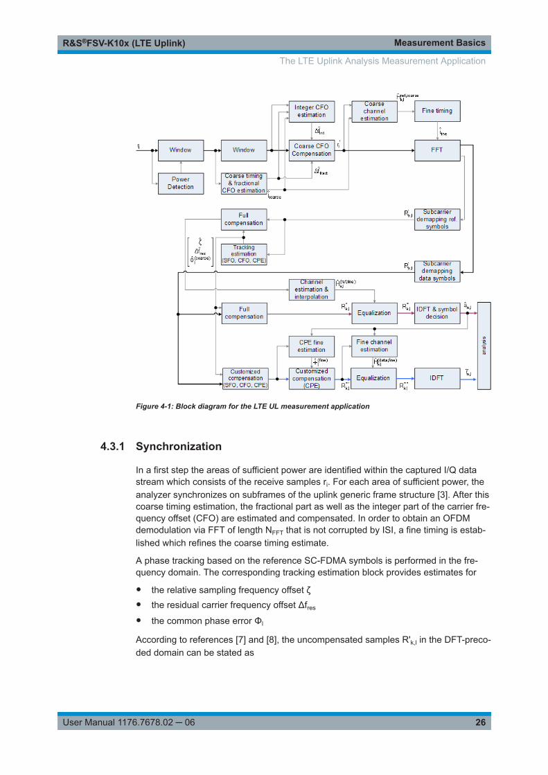
The block diagram in Figure 4-1 shows the general structure of the LTE uplink mea-surement application from the capture buffer containing the I/Q data up to the actualanalysis block.
After synchronization a fully compensated signal is produced in the reference path(purple) which is subsequently passed to the equalizer. An IDFT of the equalized sym-bols yields observations for the QAM transmit symbols an.l from which the data esti-mates ân,l are obtained via hard decision. Likewise a user defined compensation aswell as equalization is carried out in the measurement path (cyan) and after an IDFTthe observations of the QAM transmit symbols are provided. Accordingly, the measure-ment path might still contain impairments which are compensated in the referencepath. The symbols of both signal processing paths form the basis for the analysis.
The LTE Uplink Analysis Measurement Application
Measurement BasicsR&S®FSV-K10x (LTE Uplink)
26User Manual 1176.7678.02 ─ 06
Figure 4-1: Block diagram for the LTE UL measurement application
4.3.1 Synchronization
In a first step the areas of sufficient power are identified within the captured I/Q datastream which consists of the receive samples ri. For each area of sufficient power, theanalyzer synchronizes on subframes of the uplink generic frame structure [3]. After thiscoarse timing estimation, the fractional part as well as the integer part of the carrier fre-quency offset (CFO) are estimated and compensated. In order to obtain an OFDMdemodulation via FFT of length NFFT that is not corrupted by ISI, a fine timing is estab-lished which refines the coarse timing estimate.
A phase tracking based on the reference SC-FDMA symbols is performed in the fre-quency domain. The corresponding tracking estimation block provides estimates for
● the relative sampling frequency offset ζ● the residual carrier frequency offset Δfres
● the common phase error Φl
According to references [7] and [8], the uncompensated samples R'k,l in the DFT-preco-ded domain can be stated as
The LTE Uplink Analysis Measurement Application

Measurement BasicsR&S®FSV-K10x (LTE Uplink)
27User Manual 1176.7678.02 ─ 06
lklTfNNjlkNNjj
lklklk NeeeHARCFOres
resFFTS
SFO
FFTS
CPE
l,
22,,
',
.
Equation 4-1:
with
● the DFT precoded data symbol Ak,l on subcarrier k at SC-FDMA symbol l,
● the channel transfer function Hk,l,
● the number of Nyquist samples NS within the total duration TS,
● the duration of the useful part of the SC-FDMA symbol T=TS-Tg
● the independent and Gaussian distributed noise sample Nk,l
Within one SC-FDMA symbol, both the CPE and the residual CFO cause the samephase rotation for each subcarrier, while the rotation due to the SFO depends linearlyon the subcarrier index. A linear phase increase in symbol direction can be observedfor the residual CFO as well as for the SFO.
The results of the tracking estimation block are used to compensate the samples R'k,l
completely in the reference path and according to the user settings in the measure-ment path. Thus the signal impairments that are of interest to the user are left uncom-pensated in the measurement path.
After having decoded the data symbols in the reference path, an additional data-aidedphase tracking can be utilized to refine the common phase error estimation.
4.3.2 Analysis
The analysis block of the EUTRA/LTE uplink measurement application allows to com-pute a variety of measurement variables.
EVM
The most important variable is the error vector magnitude which is defined as
2,
,,,
ˆ~
ln
lnlnkl
aE
arEVM
Equation 4-2:
for QAM symbol n before precoding and SC-FDMA symbol l. Since the normalizedaverage power of all possible constellations is 1, the equation can be simplified to
lnlnln arEVM ,,, ˆ~
Equation 4-3:
The average EVM of all data subcarriers is then
The LTE Uplink Analysis Measurement Application
Measurement BasicsR&S®FSV-K10x (LTE Uplink)
28User Manual 1176.7678.02 ─ 06
1
0
1
0
2,
1 LB TXN
l
N
nln
TXDSdata EVM
NNEVM
Equation 4-4:
for NDS SC-FDMA data symbols and the NTX allocated subcarriers.
I/Q imbalance
The I/Q imbalance contained in the continuous received signal r(t) can be written as
tsjQtsItr
Equation 4-5:
where s(t) is the transmit signal and I and Q are the weighting factors describing theI/Q imbalance. We define that I:=1 and Q:=1+ΔQ.
The I/Q imbalance estimation makes it possible to evaluate the
|1|balancegain modulator Q
Equation 4-6:
and the
}1arg{mismatch quadrature Q
Equation 4-7:
based on the complex-valued estimate .
Basic in-band emissions measurement
The in-band emissions are a measure of the interference falling into the non-allocatedresources blocks.
The relative in-band emissions are given by
S
RB
Tt
Nc
cRBS
RBabsoluteRBrelative
ftYNT
EmissionsEmissions 1122,1
Equation 4-8:
where TS is a set |TS| of SC-FDMA symbols with the considered modulation schemebeing active within the measurement period, ΔRB is the starting frequency offsetbetween the allocated RB and the measured non-allocated RB (e.g. ΔRB=1 or ΔRB=-1for the first adjacent RB), c is the lower edge of the allocated BW, and Y(t,f) is the fre-quency domain signal evaluated for in-band emissions. NRB is the number of allocatedRBs .
The basic in-band emissions measurement interval is defined over one slot in the timedomain.
The LTE Uplink Analysis Measurement Application

Measurement BasicsR&S®FSV-K10x (LTE Uplink)
29User Manual 1176.7678.02 ─ 06
Other measurement variables
Without going into detail, the EUTRA/LTE uplink measurement application additionallyprovides the following results:
● Total power● Constellation diagram● Group delay● I/Q offset● Crest factor● Spectral flatness
4.4 SRS EVM Calculation
In order to calculate an accurate EVM, a channel estimation needs to be done prior tothe EVM calculation. However, the channel estimation requires a minimum of tworesource elements containing reference symbols on a subcarrier. Depending on thecurrent Channel Estimation Range setting, this means that either at least two referencesymbols ("Pilot Only") or one reference symbol and at least one data symbol ("Pilotand Payload") need to be available on the subcarrier the EVM is to be measured.
For PUSCH, PUCCH and PRACH regions, these conditions are normally fulfilledbecause the DMRS (= Demodulation Reference Signal) is already included. However,the SRS may also be located on subcarriers which do not occupy any other referencesymbols (see Figure 4-2).
Figure 4-2: No EVM can be measured for the SRS
In this case it is not reasonable to calculate an EVM and no SRS EVM value will bedisplayed for the corresponding subframe.
SRS EVM Calculation

Measurement BasicsR&S®FSV-K10x (LTE Uplink)
30User Manual 1176.7678.02 ─ 06
If the SRS subcarriers contain two DMRS symbols (or one DMRS and one PUSCH for"Pilot and Payload" channel estimation range) the SRS EVM can be measured (seeFigure 4-3).
Figure 4-3: The EVM of the complete SRS can be measured
The SRS allocation might cover subcarriers which partly fulfill the conditions mentionedabove and partly do not. In this case the EVM value given in the Allocation Summarywill be calculated based only on the subcarriers which fulfill the above requirements(see Figure 4-4).
Figure 4-4: The EVM for parts of the SRS can be measured
SRS EVM Calculation

Measurements and Result DisplaysR&S®FSV-K10x (LTE Uplink)
31User Manual 1176.7678.02 ─ 06
5 Measurements and Result DisplaysThe LTE measurement application features several measurements to examine andanalyze different aspects of an LTE signal.
The source of the data that is processed is either a live signal or a previously recordedsignal whose characteristics have been saved to a file. For more information see"Selecting the Input Source" on page 61.
For more information on the functionality to actually perform the measurement seeChapter 6.1, "Performing Measurements", on page 49.
● Numerical Results...................................................................................................31● Measuring the Power Over Time............................................................................ 34● Measuring the Error Vector Magnitude (EVM)........................................................ 36● Measuring the Spectrum.........................................................................................38● Measuring the Symbol Constellation.......................................................................44● Measuring Statistics................................................................................................45● 3GPP Test Scenarios..............................................................................................48
5.1 Numerical Results
Result Summary............................................................................................................31
Result SummaryThe Result Summary shows all relevant measurement results in numerical form, com-bined in one table.
▶ Press the "Display (List Graph)" softkey so that the "List" element is highlighted toview the Result Summary.
Remote command:
DISPlay[:WINDow<n>]:TABLe on page 98
Contents of the result summaryThe contents of the result summary depend on the analysis mode you have selected.The first screenshot shows the results for "PUSCH/PUCCH" analysis mode, the sec-ond one those for "PRACH" analysis mode.
Numerical Results

Measurements and Result DisplaysR&S®FSV-K10x (LTE Uplink)
32User Manual 1176.7678.02 ─ 06
Figure 5-1: Result summary in PUSCH/PUCCH analysis mode
The table is split in two parts. The first part shows results that refer to the completeframe. It also indicates limit check results where available. The font of 'Pass' results isgreen and that of 'Fail' results is red.
In addition to the red font, the application also puts a red star ( ) in front offailed results.
The second part of the table shows results that refer to a specific selection of theframe. The statistic is always evaluated over the slots. The header row of the tablecontains information about the selection you have made (like the subframe). Note: The EVM results on a frame level (first part of the table) are calculated asdefined by 3GPP at the edges of the cyclic prefix.The other EVM results (lower part of the table) are calculated at the optimal timingposition in the middle of the cyclic prefix.Because of inter-symbol interference, the EVM calculated at the edges of the cyclicprefix is higher than the EVM calculated in the middle of the cyclic prefix.By default, all EVM results are in %. To view the EVM results in dB, change the EVMUnit.
Numerical Results
Measurements and Result DisplaysR&S®FSV-K10x (LTE Uplink)
33User Manual 1176.7678.02 ─ 06
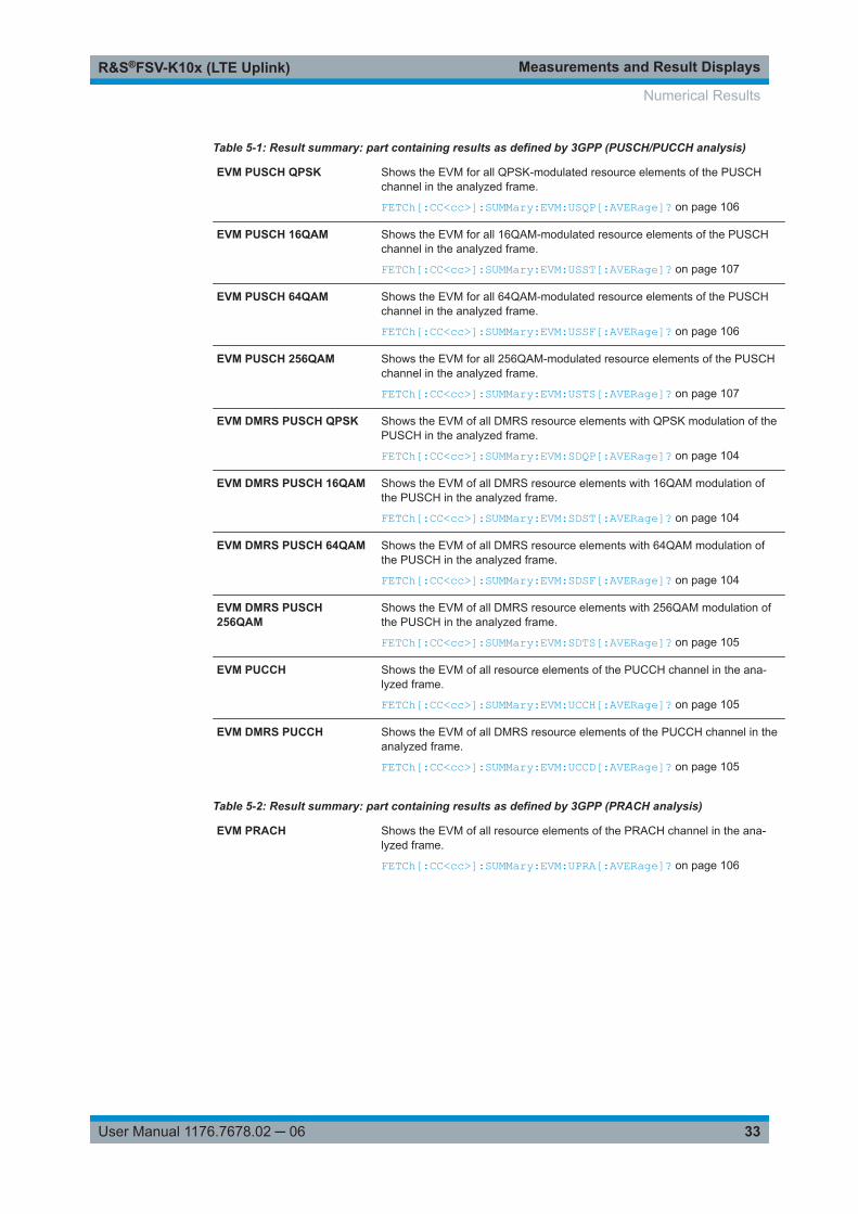
Table 5-1: Result summary: part containing results as defined by 3GPP (PUSCH/PUCCH analysis)
EVM PUSCH QPSK Shows the EVM for all QPSK-modulated resource elements of the PUSCHchannel in the analyzed frame.
FETCh[:CC<cc>]:SUMMary:EVM:USQP[:AVERage]? on page 106
EVM PUSCH 16QAM Shows the EVM for all 16QAM-modulated resource elements of the PUSCHchannel in the analyzed frame.
FETCh[:CC<cc>]:SUMMary:EVM:USST[:AVERage]? on page 107
EVM PUSCH 64QAM Shows the EVM for all 64QAM-modulated resource elements of the PUSCHchannel in the analyzed frame.
FETCh[:CC<cc>]:SUMMary:EVM:USSF[:AVERage]? on page 106
EVM PUSCH 256QAM Shows the EVM for all 256QAM-modulated resource elements of the PUSCHchannel in the analyzed frame.
FETCh[:CC<cc>]:SUMMary:EVM:USTS[:AVERage]? on page 107
EVM DMRS PUSCH QPSK Shows the EVM of all DMRS resource elements with QPSK modulation of thePUSCH in the analyzed frame.
FETCh[:CC<cc>]:SUMMary:EVM:SDQP[:AVERage]? on page 104
EVM DMRS PUSCH 16QAM Shows the EVM of all DMRS resource elements with 16QAM modulation ofthe PUSCH in the analyzed frame.
FETCh[:CC<cc>]:SUMMary:EVM:SDST[:AVERage]? on page 104
EVM DMRS PUSCH 64QAM Shows the EVM of all DMRS resource elements with 64QAM modulation ofthe PUSCH in the analyzed frame.
FETCh[:CC<cc>]:SUMMary:EVM:SDSF[:AVERage]? on page 104
EVM DMRS PUSCH256QAM
Shows the EVM of all DMRS resource elements with 256QAM modulation ofthe PUSCH in the analyzed frame.
FETCh[:CC<cc>]:SUMMary:EVM:SDTS[:AVERage]? on page 105
EVM PUCCH Shows the EVM of all resource elements of the PUCCH channel in the ana-lyzed frame.
FETCh[:CC<cc>]:SUMMary:EVM:UCCH[:AVERage]? on page 105
EVM DMRS PUCCH Shows the EVM of all DMRS resource elements of the PUCCH channel in theanalyzed frame.
FETCh[:CC<cc>]:SUMMary:EVM:UCCD[:AVERage]? on page 105
Table 5-2: Result summary: part containing results as defined by 3GPP (PRACH analysis)
EVM PRACH Shows the EVM of all resource elements of the PRACH channel in the ana-lyzed frame.
FETCh[:CC<cc>]:SUMMary:EVM:UPRA[:AVERage]? on page 106
Numerical Results

Measurements and Result DisplaysR&S®FSV-K10x (LTE Uplink)
34User Manual 1176.7678.02 ─ 06
Table 5-3: Result summary: part containing results for a specific selection
EVM All Shows the EVM for all resource elements in the analyzed frame.
FETCh[:CC<cc>]:SUMMary:EVM[:ALL][:AVERage]? on page 103
EVM Phys Channel Shows the EVM for all physical channel resource elements in the analyzedframe.
A physical channel corresponds to a set of resource elements carrying infor-mation from higher layers. PUSCH, PUCCH and PRACH are physical chan-nels. For more information, see 3GPP 36.211.
FETCh[:CC<cc>]:SUMMary:EVM:PCHannel[:AVERage]? on page 103
("PUSCH/PUCCH" analysis mode only.)
EVM Phys Signal Shows the EVM for all physical signal resource elements in the analyzedframe.
The reference signal is a physical signal. For more information, see 3GPP36.211.
FETCh[:CC<cc>]:SUMMary:EVM:PSIGnal[:AVERage]? on page 103
("PUSCH/PUCCH" analysis mode only.)
Frequency Error Shows the difference in the measured center frequency and the referencecenter frequency.
FETCh[:CC<cc>]:SUMMary:FERRor[:AVERage]? on page 107
Sampling Error Shows the difference in measured symbol clock and reference symbol clockrelative to the system sampling rate.
FETCh[:CC<cc>]:SUMMary:SERRor[:AVERage]? on page 109
I/Q Offset Shows the power at spectral line 0 normalized to the total transmitted power.
FETCh[:CC<cc>]:SUMMary:IQOFfset[:AVERage]? on page 108
I/Q Gain Imbalance Shows the logarithm of the gain ratio of the Q-channel to the I-channel.
FETCh[:CC<cc>]:SUMMary:GIMBalance[:AVERage]? on page 108
I/Q Quadrature Error Shows the measure of the phase angle between Q-channel and I-channeldeviating from the ideal 90 degrees.
FETCh[:CC<cc>]:SUMMary:QUADerror[:AVERage]? on page 109
Power Shows the average time domain power of the allocated resource blocks of theanalyzed signal.
FETCh[:CC<cc>]:SUMMary:POWer[:AVERage]? on page 109
Crest Factor Shows the peak-to-average power ratio of captured signal.
FETCh[:CC<cc>]:SUMMary:CRESt[:AVERage]? on page 102
5.2 Measuring the Power Over Time
This chapter contains information on all measurements that show the power of a signalover time.
Capture Buffer...............................................................................................................35
Measuring the Power Over Time

Measurements and Result DisplaysR&S®FSV-K10x (LTE Uplink)
35User Manual 1176.7678.02 ─ 06
Capture BufferThe "Capture Buffer" shows the complete range of captured data for the last data cap-ture.
The x-axis represents time. The maximum value of the x-axis is equal to the CaptureTime.
The y-axis represents the amplitude of the captured I/Q data in dBm (for RF input).
Figure 5-2: Capture buffer without zoom
A green bar at the bottom of the diagram represents the frame that is currently ana-lyzed.
A green vertical line at the beginning of the green bar in the capture buffer representsthe subframe start. The diagram also contains the "Start Offset" value. This value is thetime difference between the subframe start and capture buffer start.
When you zoom into the diagram, you will see that the bar is interrupted at certainpositions. Each small bar indicates the useful parts of the OFDM symbol.
Figure 5-3: Capture buffer after a zoom has been applied
Remote command: Selection: CALCulate<n>:FEED 'PVT:CBUF'Query (y-axis): TRACe:DATA?Subframe start offset: FETCh[:CC<cc>]:SUMMary:TFRame? on page 110
Measuring the Power Over Time

Measurements and Result DisplaysR&S®FSV-K10x (LTE Uplink)
36User Manual 1176.7678.02 ─ 06
5.3 Measuring the Error Vector Magnitude (EVM)
This chapter contains information on all measurements that show the error vector mag-nitude (EVM) of a signal.
The EVM is one of the most important indicators for the quality of a signal. For moreinformation on EVM calculation methods refer to Chapter 4, "Measurement Basics",on page 24.
EVM vs Carrier..............................................................................................................36EVM vs Symbol.............................................................................................................37EVM vs Subframe......................................................................................................... 37
EVM vs CarrierThe "EVM vs Carrier" result display shows the error vector magnitude (EVM) of thesubcarriers. With the help of a marker, you can use it as a debugging technique toidentify any subcarriers whose EVM is too high.
The results are based on an average EVM that is calculated over the resource ele-ments for each subcarrier. This average subcarrier EVM is determined for each ana-lyzed slot in the capture buffer.
If you analyze all slots, the result display contains three traces.● Average EVM
This trace shows the subcarrier EVM, averaged over all slots.● Minimum EVM
This trace shows the lowest (average) subcarrier EVM that has been found overthe analyzed slots.
● Maximum EVMThis trace shows the highest (average) subcarrier EVM that has been found overthe analyzed slots.
If you select and analyze one slot only, the result display contains one trace that showsthe subcarrier EVM for that slot only. Average, minimum and maximum values in thatcase are the same. For more information, see "Slot Selection" on page 83.
The x-axis represents the center frequencies of the subcarriers. The y-axis shows theEVM in % or in dB, depending on the EVM Unit.
Remote command: Selection: CALCulate<n>:FEED 'EVM:EVCA'Query (y-axis): TRACe:DATA?
Measuring the Error Vector Magnitude (EVM)

Measurements and Result DisplaysR&S®FSV-K10x (LTE Uplink)
37User Manual 1176.7678.02 ─ 06
EVM vs SymbolThe "EVM vs Symbol" result display shows the error vector magnitude (EVM) of theOFDM symbols. You can use it as a debugging technique to identify any symbolswhose EVM is too high.
The results are based on an average EVM that is calculated over all subcarriers thatare part of a certain OFDM symbol. This average OFDM symbol EVM is determined forall OFDM symbols in each analyzed slot.
The x-axis represents the OFDM symbols, with each symbol represented by a dot onthe line. Any missing connections from one dot to another mean that theR&S FSVA/FSV could not determine the EVM for that symbol.
The number of displayed symbols depends on the subframe selection and the length ofthe cyclic prefix.
For TDD signals, the result display does not show OFDM symbols that are not part ofthe measured link direction.
On the y-axis, the EVM is plotted either in % or in dB, depending on the EVM Unit.
Remote command: Selection: CALCulate<n>:FEED 'EVM:EVSY'Query (y-axis): TRACe:DATA?
EVM vs SubframeThe "EVM vs Subframe" result display shows the Error Vector Magnitude (EVM) foreach subframe. You can use it as a debugging technique to identify a subframe whoseEVM is too high.
The result is an average over all subcarriers and symbols of a specific subframe.
The x-axis represents the subframes, with the number of displayed subframes being10.
On the y-axis, the EVM is plotted either in % or in dB, depending on the EVM Unit.
Measuring the Error Vector Magnitude (EVM)

Measurements and Result DisplaysR&S®FSV-K10x (LTE Uplink)
38User Manual 1176.7678.02 ─ 06
Remote command: Selection: CALCulate<n>:FEED 'EVM:EVSU'Query (y-axis): TRACe:DATA?
5.4 Measuring the Spectrum
This chapter contains information on all measurements that show the power of a signalin the frequency domain.
In addition to the I/Q measurements, spectrum measurements also include two fre-quency sweep measurements, the Spectrum Emission Mask and the Adjacent Chan-nel Leakage Ratio.
● Frequency Sweep Measurements.......................................................................... 38● I/Q Measurements...................................................................................................42
5.4.1 Frequency Sweep Measurements
The Spectrum Emission Mask (SEM) and Adjacent Channel Leakage Ratio (ACLR)measurements are the only frequency sweep measurements available for the LTEmeasurement application. They do not use the I/Q data all other measurements use.Instead those measurements sweep the frequency spectrum every time you run a newmeasurement. Therefore it is not possible to to run an I/Q measurement and then viewthe results in the frequency sweep measurements and vice-versa. Also because eachof the frequency sweep measurements uses different settings to obtain signal data it isnot possible to run a frequency sweep measurement and view the results in anotherfrequency sweep measurement.
Frequency sweep measurements are available if RF input is selected.
5.4.1.1 Available Measurements
Spectrum Emission Mask (SEM).................................................................................. 39└ Result diagram................................................................................................39└ Result summary..............................................................................................39
Measuring the Spectrum

Measurements and Result DisplaysR&S®FSV-K10x (LTE Uplink)
39User Manual 1176.7678.02 ─ 06
Adjacent Channel Leakage Ratio (ACLR).....................................................................40└ Result diagram................................................................................................41└ Result summary..............................................................................................41
Spectrum Emission Mask (SEM)The "Spectrum Emission Mask" (SEM) measurement shows the quality of the mea-sured signal by comparing the power values in the frequency range near the carrieragainst a spectral mask that is defined by the 3GPP specifications. In this way, you cantest the performance of the DUT and identify the emissions and their distance to thelimit.
For a comprehensive description of the SEM measurement, refer to the user manual ofthe R&S FSVA/FSV.
Remote command: Selection: CALCulate<n>:FEED 'SPEC:SEM'
Result diagram ← Spectrum Emission Mask (SEM)The result diagram is a graphic representation of the signal with a trace that shows themeasured signal. The SEM is represented by a red line.
If any measured power levels are above that limit line, the test fails. If all power levelsare inside the specified limits, the test passes. The application labels the limit line toindicate whether the limit check has passed or failed.
The x-axis represents the frequency with a frequency span that relates to the specifiedLTE channel bandwidths. The y-axis shows the signal power in dBm.
Remote command: Result query: TRACe:DATA?
Result summary ← Spectrum Emission Mask (SEM)The result summary shows the signal characteristics in numerical form. Each row inthe table corresponds to a certain SEM range. The columns contain the range charac-teristics. If a limit fails, the range characteristics turn red.● Start / Stop Freq Rel
Shows the start and stop frequency of each section of the spectrum emission maskrelative to the center frequency.
● RBWShows the resolution bandwidth of each section of the spectrum emission mask.
● Freq at Δ to Limit
Measuring the Spectrum

Measurements and Result DisplaysR&S®FSV-K10x (LTE Uplink)
40User Manual 1176.7678.02 ─ 06
Shows the absolute frequency whose power measurement being closest to thelimit line for the corresponding frequency segment.
● Power AbsShows the absolute measured power of the frequency whose power is closest tothe limit. The application evaluates this value for each frequency segment.
● Power RelShows the distance from the measured power to the limit line at the frequencywhose power is closest to the limit. The application evaluates this value for eachfrequency segment.
● Δ to LimitShows the minimal distance of the tolerance limit to the SEM trace for the corre-sponding frequency segment. Negative distances indicate that the trace is belowthe tolerance limit, positive distances indicate that the trace is above the tolerancelimit.
Adjacent Channel Leakage Ratio (ACLR)The adjacent channel leakage ratio (ACLR) measurement is designed to analyze sig-nals that contain multiple signals for different radio standards. Using the ACLR mea-surement, you can determine the power of the transmit (Tx) channel and the power ofthe neighboring (adjacent) channels to the left and right of the Tx channel. Thus, theACLR measurement provides information about the power in the adjacent channels aswell as the leakage into these adjacent channels.
In the LTE application, you can analyze the power of up to two Tx channels and up totwo adjacent channels. If you analyze two Tx channels, they have to be next to eachother. The distance between the two Tx channels is variable and is defined as a Tx off-set. In the diagram, the Tx channels are labeled C0 and Cu0. For measurements ontwo Tx channels, the lower adjacent channels (cl1 and cl2) are to the left of the first Txchannel. The upper adjacent channels (cu1 and cu2) are to the right of the second Txchannel.
When you measure the ACLR in the LTE application, the R&S FSVA/FSV automaticallyselects appropriate ACLR settings based on the selected channel bandwidth.
For a comprehensive description of the ACLR measurement, refer to the user manualof the R&S FSVA/FSV.
Remote command: Selection: CALCulate<n>:FEED 'SPEC:ACP'
Measuring the Spectrum

Measurements and Result DisplaysR&S®FSV-K10x (LTE Uplink)
41User Manual 1176.7678.02 ─ 06
Result diagram ← Adjacent Channel Leakage Ratio (ACLR)The result diagram is a graphic representation of the signals with a trace that showsthe measured signal. Individual channels (Tx and adjacent channels) are indicated byvertical lines and corresponding labels.
The x-axis represents the frequency with a frequency span that relates to the specifiedLTE channel and adjacent channel bandwidths. On the y-axis, the power is plotted indBm.
The power for the Tx channel is an absolute value in dBm. The power of the adjacentchannels is relative to the power of the Tx channel.
For measurements on two Tx channels, the power of the adjacent channels to the leftof the Tx channels are values relative to the power of the left Tx channel. The power ofthe adjacent channels on the right of the TX channels are values relative to the powerof the right Tx channel.
In addition, the R&S FSVA/FSV tests the ACLR measurement results against the limitsdefined by 3GPP.
Remote command: Result query: TRACe:DATA?
Result summary ← Adjacent Channel Leakage Ratio (ACLR)The result summary shows the signal characteristics in numerical form. Each row inthe table corresponds to a certain channel type (Tx, adjacent channel). The columnscontain the channel characteristics.● Channel
Shows the channel type (Tx, adjacent or alternate channel).Note that if you measure two Tx channels, each Tx channel only has one set ofadjacent channels. The first Tx channel (C0) those to its left, the second Tx chan-nel (Cu0) those to its right.
● BandwidthShows the channel bandwidth.
● SpacingShows the channel spacing.
● PowerShows the power of the Tx channel.
● Lower / UpperShows the relative power of the lower and upper adjacent and alternate channels.The values turn red if the power violates the limits.
● Limit
Measuring the Spectrum
Measurements and Result DisplaysR&S®FSV-K10x (LTE Uplink)
42User Manual 1176.7678.02 ─ 06
Shows the limit of that channel, if one is defined.
Remote command: Result query: CALCulate<n>:MARKer<m>:FUNCtion:POWer<sb>:RESult[:CURRent]?
5.4.2 I/Q Measurements
● Inband Emissions....................................................................................................42● Flatness (Flat | Grdel | Diff)..................................................................................... 42
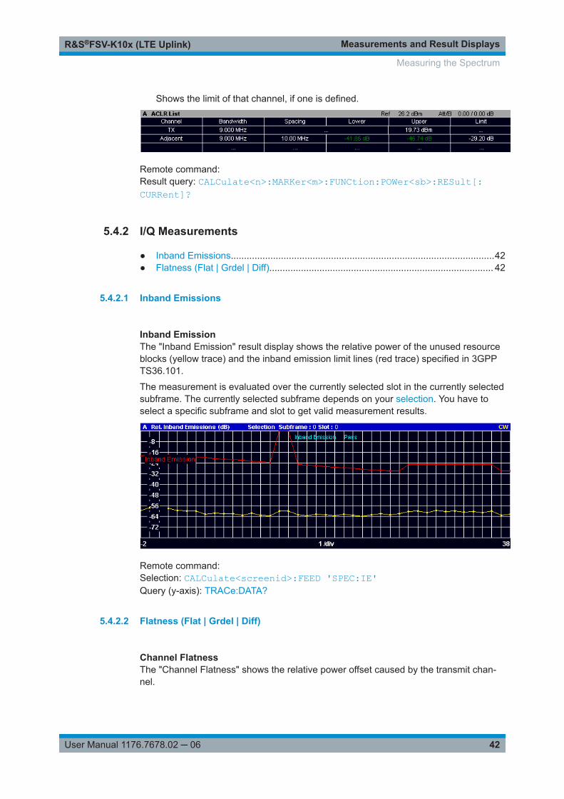
5.4.2.1 Inband Emissions
Inband EmissionThe "Inband Emission" result display shows the relative power of the unused resourceblocks (yellow trace) and the inband emission limit lines (red trace) specified in 3GPPTS36.101.
The measurement is evaluated over the currently selected slot in the currently selectedsubframe. The currently selected subframe depends on your selection. You have toselect a specific subframe and slot to get valid measurement results.
Remote command: Selection: CALCulate<screenid>:FEED 'SPEC:IE'Query (y-axis): TRACe:DATA?
5.4.2.2 Flatness (Flat | Grdel | Diff)
Channel FlatnessThe "Channel Flatness" shows the relative power offset caused by the transmit chan-nel.
Measuring the Spectrum

Measurements and Result DisplaysR&S®FSV-K10x (LTE Uplink)
43User Manual 1176.7678.02 ─ 06
The measurement is evaluated over the currently selected slot in the currently selectedsubframe.
The currently selected subframe depends on your selection.
The x-axis represents the frequency. On the y-axis, the channel flatness is plotted indB.
Remote command: Selection: CALCulate<n>:FEED 'SPEC:FLAT'Query (y-axis): TRACe:DATA?
Group DelayThis "Group Delay" shows the group delay of each subcarrier.
The measurement is evaluated over the currently selected slot in the currently selectedsubframe.
The currently selected subframe depends on your selection.
The x-axis represents the frequency. On the y-axis, the group delay is plotted in ns.
Remote command: Selection: CALCulate<n>:FEED 'SPEC:GDEL'Query (y-axis): TRACe:DATA?
Channel Flatness DifferenceThe "Channel Flatness Difference" shows the level difference in the spectrum flatnessresult between two adjacent physical subcarriers.
The measurement is evaluated over the currently selected slot in the currently selectedsubframe.
Measuring the Spectrum

Measurements and Result DisplaysR&S®FSV-K10x (LTE Uplink)
44User Manual 1176.7678.02 ─ 06
The currently selected subframe depends on your selection.
The x-axis represents the frequency. On the y-axis, the power is plotted in dB.
Remote command: Selection: CALCulate<n>:FEED 'SPEC:FDIF'Query (y-axis): TRACe:DATA?
5.5 Measuring the Symbol Constellation
This chapter contains information on all measurements that show the constellation of asignal.
Constellation Diagram...................................................................................................44DFT Precod Constellation............................................................................................. 45
Constellation DiagramThe "Constellation Diagram" shows the in-phase and quadrature phase results and isan indicator of the quality of the modulation of the signal.
In the default state, the result display evaluates the full range of the measured inputdata.
The ideal points for the selected modulation scheme are displayed for reference purpo-ses.
Each color represents a modulation type.● : RBPSK● : MIXTURE● : QPSK● : 16QAM● : 64QAM● : 256QAM● : PSK (CAZAC)You can filter the results by changing the evaluation range.
Measuring the Symbol Constellation

Measurements and Result DisplaysR&S®FSV-K10x (LTE Uplink)
45User Manual 1176.7678.02 ─ 06
The constellation diagram also contains information about the current evaluationrange, including the number of points that are displayed in the diagram.
Remote command: Selection: CALCulate<n>:FEED 'CONS:CONS'Query: TRACe:DATA?
DFT Precod ConstellationThe "DFT Precod Constellation" result display shows the inphase and quadraturephase results. It shows the data without the DFT precoding. The result display evalu-ates the full range of the measured input data. You can filter the results in the Constel-lation Selection dialog box.
Remote command: Selecting the result display: CALCulate<screenid>:FEED 'CONS:DFTC'
5.6 Measuring Statistics
This chapter contains information on all measurements that show the statistics of a sig-nal.
CCDF............................................................................................................................ 46Allocation Summary...................................................................................................... 46Bitstream....................................................................................................................... 47
Measuring Statistics
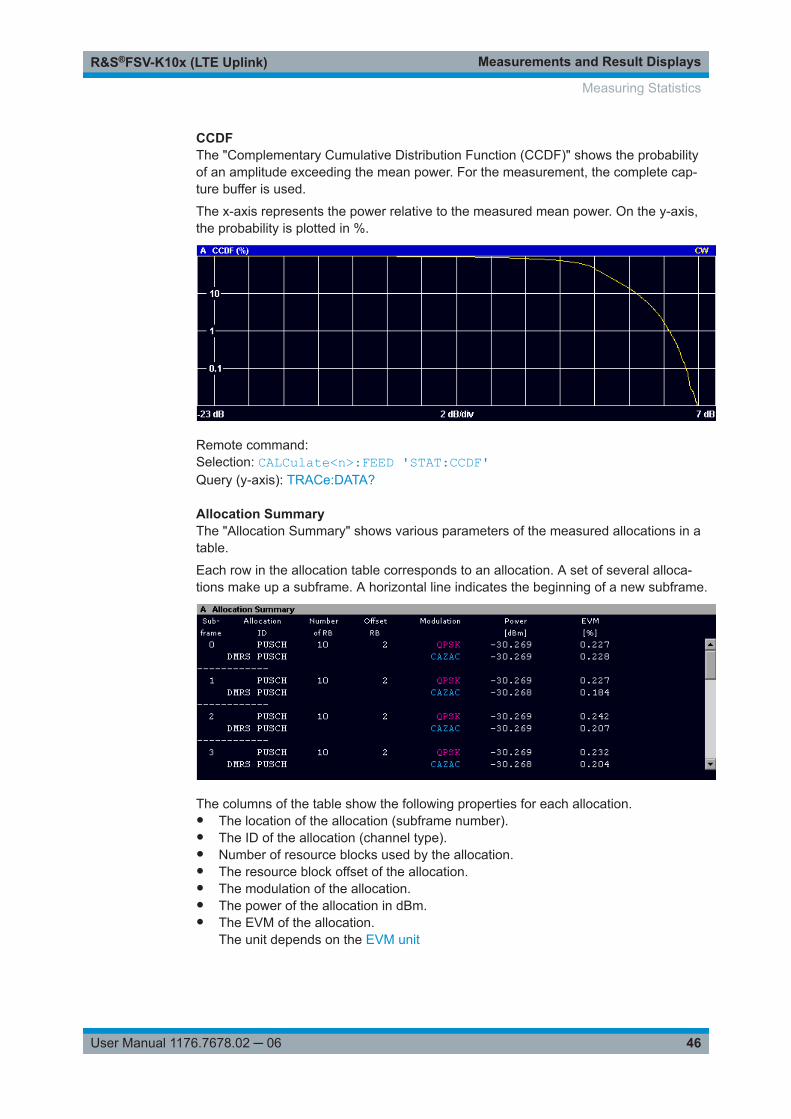
Measurements and Result DisplaysR&S®FSV-K10x (LTE Uplink)
46User Manual 1176.7678.02 ─ 06
CCDFThe "Complementary Cumulative Distribution Function (CCDF)" shows the probabilityof an amplitude exceeding the mean power. For the measurement, the complete cap-ture buffer is used.
The x-axis represents the power relative to the measured mean power. On the y-axis,the probability is plotted in %.
Remote command: Selection: CALCulate<n>:FEED 'STAT:CCDF'Query (y-axis): TRACe:DATA?
Allocation SummaryThe "Allocation Summary" shows various parameters of the measured allocations in atable.
Each row in the allocation table corresponds to an allocation. A set of several alloca-tions make up a subframe. A horizontal line indicates the beginning of a new subframe.
The columns of the table show the following properties for each allocation.● The location of the allocation (subframe number).● The ID of the allocation (channel type).● Number of resource blocks used by the allocation.● The resource block offset of the allocation.● The modulation of the allocation.● The power of the allocation in dBm.● The EVM of the allocation.
The unit depends on the EVM unit
Measuring Statistics

Measurements and Result DisplaysR&S®FSV-K10x (LTE Uplink)
47User Manual 1176.7678.02 ─ 06
Click once on the header row to open a dialog box that allows you to add and removecolumns.
Remote command: Selection: CALCulate<n>:FEED 'STAT:ASUM'Query: TRACe:DATA?
BitstreamThe "Bitstream" shows the demodulated data stream for the data allocations.
Depending on the bitstream format, the numbers represent either bits (bit order) orsymbols (symbol order).
For the bit format, each number represents one raw bit. For the symbol format, the bitsthat belong to one symbol are shown as hexadecimal numbers with two digits.
Resource elements that do not contain data or are not part of the transmission are rep-resented by a "-".
If a symbol could not be decoded because the number of layers exceeds the numberof receive antennas, the application shows a "#" sign.
The table contains the following information:● Subframe
Number of the subframe the bits belong to.● Allocation ID
Channel the bits belong to.● Codeword
Code word of the allocation.● Modulation
Modulation type of the channels.● Symbol Index or Bit Index
Indicates the position of the table row's first bit or symbol within the completestream.
● Bit StreamThe actual bit stream.
Remote command: Selection: CALCulate<n>:FEED 'STAT:BSTR'Query: TRACe:DATA?
Measuring Statistics
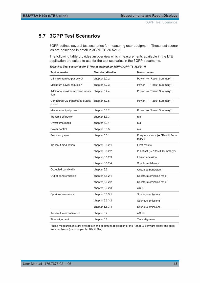
Measurements and Result DisplaysR&S®FSV-K10x (LTE Uplink)
48User Manual 1176.7678.02 ─ 06
5.7 3GPP Test Scenarios
3GPP defines several test scenarios for measuring user equipment. These test scenar-ios are described in detail in 3GPP TS 36.521-1.
The following table provides an overview which measurements available in the LTEapplication are suited to use for the test scenarios in the 3GPP documents.
Table 5-4: Test scenarios for E-TMs as defined by 3GPP (3GPP TS 36.521-1)
Test scenario Test described in Measurement
UE maximum output power chapter 6.2.2 Power (➙ "Result Summary")
Maximum power reduction chapter 6.2.3 Power (➙ "Result Summary")
Additional maximum power reduc-tion
chapter 6.2.4 Power (➙ "Result Summary")
Configured UE-transmitted outputpower
chapter 6.2.5 Power (➙ "Result Summary")
Minimum output power chapter 6.3.2 Power (➙ "Result Summary")
Transmit off power chapter 6.3.3 n/a
On/off time mask chapter 6.3.4 n/a
Power control chapter 6.3.5 n/a
Frequency error chapter 6.5.1 Frequency error (➙ "Result Sum-mary")
Transmit modulation chapter 6.5.2.1 EVM results
chapter 6.5.2.2 I/Q offset (➙ "Result Summary")
chapter 6.5.2.3 Inband emission
chapter 6.5.2.4 Spectrum flatness
Occupied bandwidth chapter 6.6.1 Occupied bandwidth1
Out of band emission chapter 6.6.2.1 Spectrum emission mask
chapter 6.6.2.2 Spectrum emission mask
chapter 6.6.2.3 ACLR
Spurious emissions chapter 6.6.3.1 Spurious emissions1
chapter 6.6.3.2 Spurious emissions1
chapter 6.6.3.3 Spurious emissions1
Transmit intermodulation chapter 6.7 ACLR
Time alignment chapter 6.8 Time alignment
1these measurements are available in the spectrum application of the Rohde & Schwarz signal and spec-trum analyzers (for example the R&S FSW)
3GPP Test Scenarios

Configuring and Performing the MeasurementR&S®FSV-K10x (LTE Uplink)
49User Manual 1176.7678.02 ─ 06
6 Configuring and Performing the Measure-mentBefore you can start a measurement, you have to configure the R&S FSVA/FSV inorder to get valid measurement results. This chapter contains detailed information onall settings available in the application.
You can access the two main settings dialog boxes via the "Settings (Gen Demod)"softkey. Pressing the softkey once opens the "General Settings" dialog box. The "Gen"label in the softkey turns orange to indicate an active "General Settings" dialog box.Pressing the softkey again opens the "Demod Settings" dialog box. When the "DemodSettings" dialog box is active, the "Demod" label in the softkey turns orange.
In the "General Settings" dialog box, you can set all parameters that are related to theoverall measurement. The dialog box is made up of three tabs, one for general set-tings, one for MIMO settings and one for advanced settings. By default, the "General"tab is the active one.
In the "Demod Settings" dialog box you can set up the measurement in detail, e.g. thedemodulation configuration. The dialog box is made up of three tabs, one for configur-ing the signal configuration, one for setting up the frame configuration and one for con-figuring the control channels and miscellaneous settings. By default, the "DL Demod"tab is the active one.
You can switch between the tabs by touching the tab on the touchscreen or with thecursor keys.
● Performing Measurements......................................................................................49● Defining General Measurement Characteristics..................................................... 50● Configuring Spectrum Measurements.....................................................................57● Defining Advanced Measurement Characteristics.................................................. 60● Configuring the Signal Demodulation......................................................................63● Configuring Uplink Frames......................................................................................66● Defining Advanced Signal Characteristics.............................................................. 71● Defining the PRACH Structure................................................................................79
6.1 Performing Measurements
Access: [SWEEP]
The sweep menu contains functions that control the way the R&S FSVA/FSV performsa measurement.
Single Sweep and Continuous Sweep.......................................................................... 50Auto Level..................................................................................................................... 50Refresh..........................................................................................................................50
Performing Measurements

Configuring and Performing the MeasurementR&S®FSV-K10x (LTE Uplink)
50User Manual 1176.7678.02 ─ 06
Single Sweep and Continuous SweepIn continuous sweep mode, the R&S FSVA/FSV continuously captures data, performsmeasurements and updates the result display according to the trigger settings.
To activate single sweep mode, press the "Run Single" softkey. In single sweep mode,the R&S FSVA/FSV captures data, performs the measurement and updates the resultdisplay exactly once after the trigger event. After this process, the R&S FSVA/FSVinterrupts the measurement.
You can always switch back to continuous sweep mode with the "Run Cont" softkey.
Remote command: INITiate:CONTinuous on page 99
Auto LevelThe "Auto Level" softkey initiates a process that sets an ideal reference level for thecurrent measurement.
For more information, see "Reference Level" on page 53.
Remote command: [SENSe:]POWer:AUTO[:STATe] on page 127
RefreshUpdates the current result display in single sweep mode without capturing I/Q dataagain.
If you have changed any settings after a single sweep and use the Refresh function,the R&S FSVA/FSV updates the current measurement results regarding the new set-tings. It does not capture I/Q data again but uses the data captured last.
Remote command: INITiate:REFResh on page 100
6.2 Defining General Measurement Characteristics
The "General Settings" contain settings to describe the basic measurement configura-tion.
● Defining Signal Characteristics............................................................................... 50● Configuring the Input Level..................................................................................... 52● Configuring the Data Capture................................................................................. 54● Triggering Measurements....................................................................................... 55
6.2.1 Defining Signal Characteristics
The general signal characteristics contain settings to describe the general physicalattributes of the signal.
The signal characteristics are part of the "General" tab of the "General Settings" dialogbox.
Defining General Measurement Characteristics

Configuring and Performing the MeasurementR&S®FSV-K10x (LTE Uplink)
51User Manual 1176.7678.02 ─ 06
Selecting the LTE mode................................................................................................ 51Signal Frequency.......................................................................................................... 51
└ Center Frequency........................................................................................... 51Channel Bandwidth / Number of Resource Blocks....................................................... 52Cyclic Prefix.................................................................................................................. 52
Selecting the LTE modeThe "Mode" selects the LTE standard you are testing.
The choices you have depend on the set of options you have installed.● Option xxx-K100 enables testing of 3GPP LTE FDD signals on the downlink● Option xxx-K101 enables testing of 3GPP LTE FDD signals on the uplink● Option xxx-K102 enables testing of 3GPP LTE MIMO signals on the downlink● Option xxx-K104 enables testing of 3GPP LTE TDD signals on the downlink● Option xxx-K105 enables testing of 3GPP LTE TDD signals on the uplinkFDD and TDD are duplexing methods.● FDD mode uses different frequencies for the uplink and the downlink.● TDD mode uses the same frequency for the uplink and the downlink.Downlink (DL) and Uplink (UL) describe the transmission path.● Downlink is the transmission path from the base station to the user equipment.
The physical layer mode for the downlink is always OFDMA.● Uplink is the transmission path from the user equipment to the base station.
The physical layer mode for the uplink is always SC-FDMA.
Remote command: Link direction: CONFigure[:LTE]:LDIRection on page 123Duplexing mode: CONFigure[:LTE]:DUPLexing on page 123
Signal FrequencyFor measurements with an RF input source, you have to match the center frequencyof the analyzer to the frequency of the signal.
Center Frequency ← Signal FrequencyDefines the center frequency of the signal and thus the frequency the R&S FSVA/FSVtunes to.
The frequency range depends on the hardware configuration of the analyzer you areusing.
Remote command: Center frequency: [SENSe:]FREQuency:CENTer[:CC<cc>] on page 124
Defining General Measurement Characteristics

Configuring and Performing the MeasurementR&S®FSV-K10x (LTE Uplink)
52User Manual 1176.7678.02 ─ 06
Channel Bandwidth / Number of Resource BlocksSpecifies the channel bandwidth and number of resource blocks (RB).
The channel bandwidth and number of resource blocks (RB) are interdependent. Cur-rently, the LTE standard recommends six bandwidths (see table below).
The application also calculates the FFT size and sampling rate from the channel band-width. Those are read only.
Channel Bandwidth [MHz] 1.4 20151053
Number of Resource Blocks 6 10075502515
Sample Rate [MHz] 1.92 30.7230.7215.367.683.84
FFT Size 128 204820481024512256
Remote command: CONFigure[:LTE]:UL[:CC<cc>]:BW on page 123
Cyclic PrefixThe cyclic prefix serves as a guard interval between OFDM symbols to avoid interfer-ences. The standard specifies two cyclic prefix modes with a different length each.
The cyclic prefix mode defines the number of OFDM symbols in a slot.● Normal
A slot contains 7 OFDM symbols.● Extended
A slot contains 6 OFDM symbols.The extended cyclic prefix is able to cover larger cell sizes with higher delayspread of the radio channel.
● AutoThe application automatically detects the cyclic prefix mode in use.
Remote command: CONFigure[:LTE]:UL[:CC<cc>]:CYCPrefix on page 124
6.2.2 Configuring the Input Level
The level settings contain settings that control the input level of the analyzer.
The level settings are part of the "General" tab of the "General Settings" dialog box.
Reference Level............................................................................................................ 53└ Auto Level.......................................................................................................53
Defining General Measurement Characteristics
Configuring and Performing the MeasurementR&S®FSV-K10x (LTE Uplink)
53User Manual 1176.7678.02 ─ 06
Attenuating the Signal................................................................................................... 53└ External Attenuation........................................................................................53└ RF Attenuation................................................................................................54
Reference LevelThe reference level is the power level the analyzer expects at the RF input. Keep inmind that the power level at the RF input is the peak envelope power for signals with ahigh crest factor like LTE.
To get the best dynamic range, you have to set the reference level as low as possible.At the same time, make sure that the maximum signal level does not exceed the refer-ence level. If it does, it will overload the A/D converter, regardless of the signal power.Measurement results can deteriorate (e.g. EVM), especially for measurements withmore than one active channel near the one you are trying to measure (± 6 MHz).
Note that the signal level at the A/D converter can be stronger than the level the appli-cation displays, depending on the current resolution bandwidth. This is because theresolution bandwidths are implemented digitally after the A/D converter.
The reference level is a value in dBm.
Remote command: Reference level: DISPlay[:WINDow<n>]:TRACe<t>:Y[:SCALe]:RLEVelon page 125
Auto Level ← Reference LevelAutomatically determines the ideal reference level. The automatic leveling processmeasures the signal and defines the ideal reference signal for the measured signal.
Automatic level detection also optimizes RF attenuation.
Auto leveling slightly increases the measurement time, because of the extra levelingmeasurement prior to each sweep. By default, the R&S FSVA/FSV automaticallydefines the time for auto leveling, but you can also define it manually ("Auto LevelingTrack Time").
Remote command: Automatic: [SENSe:]POWer:AUTO[:STATe] on page 127Auto Level Track Time: [SENSe:]POWer:AUTO:TIME on page 128
Attenuating the SignalAttenuation of the signal becomes necessary if you have to reduce the power of thesignal that you have applied. Power reduction is necessary, for example, to prevent anoverload of the input mixer.
For a comprehensive information about signal attenuation, refer to the user manual ofthe R&S FSVA/FSV.
The LTE measurement application provides several attenuation modes.
External Attenuation ← Attenuating the SignalExternal attenuation controls an external attenuator if you are using one.
Remote command: DISPlay[:WINDow<n>]:TRACe<t>:Y[:SCALe]:RLEVel:OFFSet on page 125
Defining General Measurement Characteristics

Configuring and Performing the MeasurementR&S®FSV-K10x (LTE Uplink)
54User Manual 1176.7678.02 ─ 06
RF Attenuation ← Attenuating the SignalControls the RF (or mechanical) attenuator at the RF input.
If you select automatic signal attenuation, the attenuation level is coupled to the refer-ence level.
If you select manual signal attenuation, you can define an arbitrary attenuation (withinthe supported value range).
Positive values correspond to signal attenuation and negative values correspond tosignal gain.
Remote command: Level: INPut<ip>:ATTenuation<ant> on page 126
6.2.3 Configuring the Data Capture
The data capture settings contain settings that control the amount of data and the waythat the application records the LTE signal.
The data capture settings are part of the "General" tab of the "General Settings" dialogbox.
Capture Time.................................................................................................................54Overall Frame Count.....................................................................................................54Number of Frames to Analyze...................................................................................... 55Auto According to Standard.......................................................................................... 55
Capture TimeThe "Capture Time" corresponds to the time of one measurement. Therefore, it definesthe amount of data the application captures during a single measurement (or sweep).
By default, the application captures 20.1 ms of data to make sure that at least onecomplete LTE frame is captured in the measurement.
Remote command: [SENSe:]SWEep:TIME on page 129
Overall Frame CountThe "Overall Frame Count" turns the manual selection of the number of frames to cap-ture (and analyze) on and off.
When you turn on the overall frame count, you can define the number of frames to cap-ture and analyze. The measurement runs until all frames have been analyzed, even if ittakes more than one capture.
The results are an average of the captured frames.
Defining General Measurement Characteristics
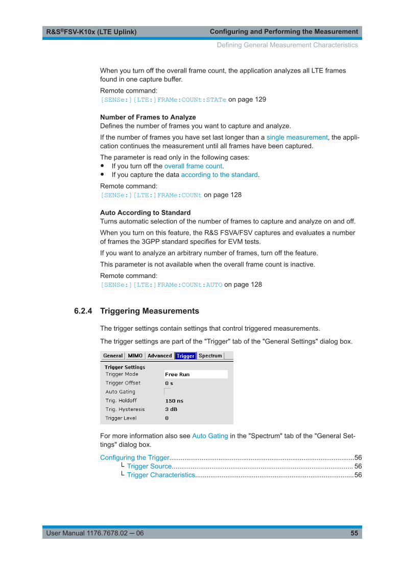
Configuring and Performing the MeasurementR&S®FSV-K10x (LTE Uplink)
55User Manual 1176.7678.02 ─ 06
When you turn off the overall frame count, the application analyzes all LTE framesfound in one capture buffer.
Remote command: [SENSe:][LTE:]FRAMe:COUNt:STATe on page 129
Number of Frames to AnalyzeDefines the number of frames you want to capture and analyze.
If the number of frames you have set last longer than a single measurement, the appli-cation continues the measurement until all frames have been captured.
The parameter is read only in the following cases:● If you turn off the overall frame count.● If you capture the data according to the standard.
Remote command: [SENSe:][LTE:]FRAMe:COUNt on page 128
Auto According to StandardTurns automatic selection of the number of frames to capture and analyze on and off.
When you turn on this feature, the R&S FSVA/FSV captures and evaluates a numberof frames the 3GPP standard specifies for EVM tests.
If you want to analyze an arbitrary number of frames, turn off the feature.
This parameter is not available when the overall frame count is inactive.
Remote command: [SENSe:][LTE:]FRAMe:COUNt:AUTO on page 128
6.2.4 Triggering Measurements
The trigger settings contain settings that control triggered measurements.
The trigger settings are part of the "Trigger" tab of the "General Settings" dialog box.
For more information also see Auto Gating in the "Spectrum" tab of the "General Set-tings" dialog box.
Configuring the Trigger..................................................................................................56└ Trigger Source................................................................................................ 56└ Trigger Characteristics....................................................................................56
Defining General Measurement Characteristics

Configuring and Performing the MeasurementR&S®FSV-K10x (LTE Uplink)
56User Manual 1176.7678.02 ─ 06
Configuring the TriggerTriggered measurements allow you to capture those parts of the signal that you arereally interested in. While the measurement runs freely and analyzes all signal data, nomatter if the signal contains information or not, a trigger initiates a measurement onlyunder certain circumstances (the trigger event).
For a detailed description of the trigger parameters, see the user manual of the I/Qanalyzer.
Trigger Source ← Configuring the TriggerThe trigger mode, or trigger source, selects the type of event that initiates a measure-ment. The R&S FSVA/FSV supports the following trigger sources.
● Free RunStarts the measurement immediately and measures continuously.
● ExternalThe trigger event is the level of an external trigger signal. The measurement startswhen this signal meets or exceeds a specified trigger level at the trigger input.
● IF PowerThe trigger event is the level of the intermediate frequency (IF). The measurementstarts when the level of the IF meets or exceeds the trigger level.
● RF PowerThe trigger event is the level measured at the RF input. The measurement startswhen the level of the signal meets or exceeds the trigger level.
● Power SensorThe trigger event is a specified level measured by a power sensor. The measure-ment starts when a power sensor measurement meets certain conditions.The power sensor as a trigger source is available with option R&S FSV-K9 and aconnected power sensor.
Remote command: TRIGger[:SEQuence]:MODE<ant> on page 134
Trigger Characteristics ← Configuring the TriggerFor all trigger sources, except "Free Run", you can define several trigger characteris-tics.● The trigger "Level" defines the signal level that initiates the measurement.
(The input field to define the trigger level opens when you select the external trig-ger source.)
● The trigger "Offset" is the time that must pass between the trigger event and thestart of the measurement. This can be a negative value (a pretrigger).
● The trigger "Slope" defines whether triggering occurs when the signal rises to thetrigger level or falls down to it.
● The trigger "Holdoff" defines a time period that must at least pass between one trig-ger event and the next.
● The trigger "Hysteresis" is available for the IF power trigger. It defines a distance tothe trigger level that the input signal must stay below to fulfill the trigger condition.
Remote command: Level (external): TRIGger[:SEQuence]:LEVel<ant>[:EXTernal<tp>]on page 133Level (IF power): TRIGger[:SEQuence]:LEVel<ant>:POWer on page 134
Defining General Measurement Characteristics

Configuring and Performing the MeasurementR&S®FSV-K10x (LTE Uplink)
57User Manual 1176.7678.02 ─ 06
Level (RF power): TRIGger[:SEQuence]:LEVel<ant>:RFPower on page 134Offset: TRIGger[:SEQuence]:HOLDoff<ant>[:TIME] on page 132Hysteresis: TRIGger[:SEQuence]:IFPower:HYSTeresis on page 133Holdoff: TRIGger[:SEQuence]:IFPower:HOLDoff on page 133
6.3 Configuring Spectrum Measurements
The Spectrum settings contain parameters to configure spectrum measurements(ACLR and SEM) in particular.
● General ACLR and SEM Configuration...................................................................57● Configuring SEM Measurements............................................................................ 58● Configuring ACLR Measurements.......................................................................... 59
6.3.1 General ACLR and SEM Configuration
The gate settings settings are part of the "Spectrum" tab of the "General Settings" dia-log box.
Auto Gating................................................................................................................... 57Number of TX Channels................................................................................................58Span..............................................................................................................................58
Auto GatingTurns gating for SEM and ACLR measurements on and off.
If on, the application evaluates the on-periods of an LTE TDD signal only. The applica-tion determines the location and length of the on-period from the "TDD UL/DL Alloca-tions" and the "Configuration of the Special Subframe".
Note that the automatic cyclic prefix mode detection is not supported if you have turnedon Auto Gating. In that case, you have to select the cyclic prefix mode manually.
Auto gating is available for TDD measurements in combination with an external or IFpower trigger.
If you are using an external trigger, the DUT has to send an LTE frame trigger.
Remote command: [SENSe:]SWEep:EGATe:AUTO on page 139
Configuring Spectrum Measurements

Configuring and Performing the MeasurementR&S®FSV-K10x (LTE Uplink)
58User Manual 1176.7678.02 ─ 06
Number of TX ChannelsThe application allows you to perform ACLR and SEM measurements on systems thatsupport carrier aggregation.
The number of TX channels defines the number of transmission (TX) channels toinclude in ACLR or SEM measurements.
Measurements on one or two TX channels are supported.
For measurements on two TX channels, you can additionally define the bandwidth ofthe second TX channel and the distance between the two TX channels.
For the second TX channel, you can select the bandwidths as defined by 3GPP. Formore information see "Channel Bandwidth / Number of Resource Blocks" on page 52.
Remote command: [SENSe]:POWer:ACHannel:BANDwidth:CHANnel2 on page 137[SENSe]:POWer:ACHannel:SPACing:CHANnel on page 137[SENSe]:POWer:ACHannel:TXCHannels:COUNt on page 137
SpanDefines the frequency span that is displayed in the frequency sweep result displays(SEM and ACLR).
When the "Auto Span" is on, the application automatically calculates the ideal span forthe measured signal. The ideal span for the signal depends on the channel bandwidththat you have selected.
Alternatively, you can define the span manually when you turn the "Auto Span" off.When you define the span manually, you can enter any number that is greater than thespan that would be calculated automatically. This mechanism makes sure that thespan is not too small for the signal bandwidth and the complete signal is displayed.
Note that changing the span only takes effect when you start a new measurement afteryou have changed the span.
Remote command: [SENSe]:FREQuency:SPAN:AUTO on page 136[SENSe]:FREQuency:SPAN on page 136
6.3.2 Configuring SEM Measurements
The SEM settings are part of the "Spectrum" tab of the "General Settings" dialog box.
User SEM File............................................................................................................... 58SEM Requirement.........................................................................................................59
User SEM FileTurns the evaluation of a custom Spectrum Emission Mask (SEM) on and off.
Configuring Spectrum Measurements

Configuring and Performing the MeasurementR&S®FSV-K10x (LTE Uplink)
59User Manual 1176.7678.02 ─ 06
When you turn the feature on, the application tests the signal against a custom SEMinstead of the SEM that complies to the standard.
To use a custom SEM, you have to design one in the Spectrum application and thenimport it in the LTE application with the "Load SEM File" softkey available in the "File"menu.
▶ Press the MEAS key.
▶ Press the "File Manager" softkey.
▶ Press the "Load SEM file" softkey and select the required SEM from the file man-ager.
▶ Turn on the "User SEM File" feature in the "General Settings" dialog box.
The R&S FSVA/FSV evaluates the custom SEM mask.
For a comprehensive description about designing a custom SEM in xml format, pleaserefer to the User Manual of the R&S FSVA/FSV.
Remote command: Load file: MMEMory:LOAD:SEMsettings on page 135State: [SENSe:]POWer:SEM:USERfile on page 138
SEM RequirementSelects the type of spectrum emission mask used for the Out of Band emission mea-surement.
The software supports general and specific (additional) spectrum emission masks. Thespecific spectrum emission masks contain additional SEM requirements. The addi-tional requirement masks to use for the measurement depend on the network signaledvalue "NS_03", "NS_04", "NS_06" or "NS_07".
If "NS_06" or "NS_07" is indicated in the cell, use SEM requirement "NS_06_07".
Remote command: [SENSe:]POWer:SEM:UL:REQuirement on page 138
6.3.3 Configuring ACLR Measurements
The ACLR settings are part of the "Spectrum" tab of the "General Settings" dialog box.
Assumed Adjacent Channel Carrier..............................................................................59Noise Correction........................................................................................................... 60Sweep Time.................................................................................................................. 60
Assumed Adjacent Channel CarrierSelects the assumed adjacent channel carrier for the ACLR measurement.
Configuring Spectrum Measurements
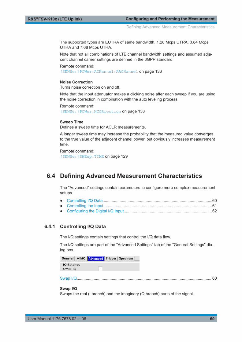
Configuring and Performing the MeasurementR&S®FSV-K10x (LTE Uplink)
60User Manual 1176.7678.02 ─ 06
The supported types are EUTRA of same bandwidth, 1.28 Mcps UTRA, 3.84 McpsUTRA and 7.68 Mcps UTRA.
Note that not all combinations of LTE channel bandwidth settings and assumed adja-cent channel carrier settings are defined in the 3GPP standard.
Remote command: [SENSe:]POWer:ACHannel:AACHannel on page 136
Noise CorrectionTurns noise correction on and off.
Note that the input attenuator makes a clicking noise after each sweep if you are usingthe noise correction in combination with the auto leveling process.
Remote command: [SENSe:]POWer:NCORrection on page 138
Sweep TimeDefines a sweep time for ACLR measurements.
A longer sweep time may increase the probability that the measured value convergesto the true value of the adjacent channel power, but obviously increases measurementtime.
Remote command: [SENSe:]SWEep:TIME on page 129
6.4 Defining Advanced Measurement Characteristics
The "Advanced" settings contain parameters to configure more complex measurementsetups.
● Controlling I/Q Data.................................................................................................60● Controlling the Input................................................................................................61● Configuring the Digital I/Q Input..............................................................................62
6.4.1 Controlling I/Q Data
The I/Q settings contain settings that control the I/Q data flow.
The I/Q settings are part of the "Advanced Settings" tab of the "General Settings" dia-log box.
Swap I/Q....................................................................................................................... 60
Swap I/QSwaps the real (I branch) and the imaginary (Q branch) parts of the signal.
Defining Advanced Measurement Characteristics

Configuring and Performing the MeasurementR&S®FSV-K10x (LTE Uplink)
61User Manual 1176.7678.02 ─ 06
Remote command: [SENSe:]SWAPiq on page 130
6.4.2 Controlling the Input
The input settings contain settings that control the input source.
The input settings are part of the "Advanced Settings" tab of the "General Settings"dialog box.
For more information on reference level see "Reference Level" on page 53.
For more information on signal attenuation see "Attenuating the Signal" on page 53.
Selecting the Input Source............................................................................................ 61Yig Filter........................................................................................................................ 61
Selecting the Input SourceThe input source selects the source of the data you would like to analyze. You caneither analyze a live signal or a signal that has been recorded previously and whosecharacteristics have been saved to a file.
You can select the input source from the "Source" dropdown menu.● RF
Captures and analyzes the data from the RF input of the spectrum analyzer in use.● Baseband (BB)
Captures and analyzes the data from the baseband input of the spectrum analyzerin use.
● Digital I/QCaptures and analyzes the data from the digital baseband input of the spectrumanalyzer in use.The digital baseband input is available with option R&S FSVA/FSV-B17.
For more information on using hardware option R&S FSVA/FSV-B17, see the manualof the R&S FSVA/FSV.
Remote command: INPut<ip>:SELect on page 130
Yig FilterR&S FSVA onlyConfigures the YIG filter.
If you want to measure broadband signals, you can configure the YIG filter for agreater bandwidth.
Defining Advanced Measurement Characteristics

Configuring and Performing the MeasurementR&S®FSV-K10x (LTE Uplink)
62User Manual 1176.7678.02 ─ 06
The process of configuring the YIG filter consists of two steps.● Selecting the mode
You can select either manual or automatic control of the YIG filter.● Selecting the state
Turns the YIG filter on and off.If inactive, you can use the maximum bandwidth. However, image frequency rejec-tion is no longer ensured.
If you have selected automatic YIG filter control, the R&S FSVA/FSV automaticallyresolves whether to use the YIG filter or not. Manual selection of the YIG filter state isnot available in that case.
Note that the R&S FSVA/FSV uses the YIG filter only for frequencies greater than3.6 GHz. If the frequency is smaller, these settings have no effect.
Remote command: INPut<ip>:FILTer:YIG[:STATe] on page 131INPut<n>:FILTer:YIG:AUTO on page 130
6.4.3 Configuring the Digital I/Q Input
The digital I/Q settings contain settings that configure the digital I/Q input.
The digital I/Q settings are part of the "Advanced Settings" tab of the "General Set-tings" dialog box.
Sampling Rate (Input Data Rate).................................................................................. 62Full Scale Level.............................................................................................................62
Sampling Rate (Input Data Rate)Defines the data sample rate at the digital baseband input.
The sample rate is available for a digital baseband input source.
Remote command: INPut<ip>:DIQ:SRATe on page 132
Full Scale LevelDefines the voltage corresponding to the maximum input value of the digital basebandinput.
Remote command: INPut<ip>:DIQ:RANGe[:UPPer] on page 132
Defining Advanced Measurement Characteristics
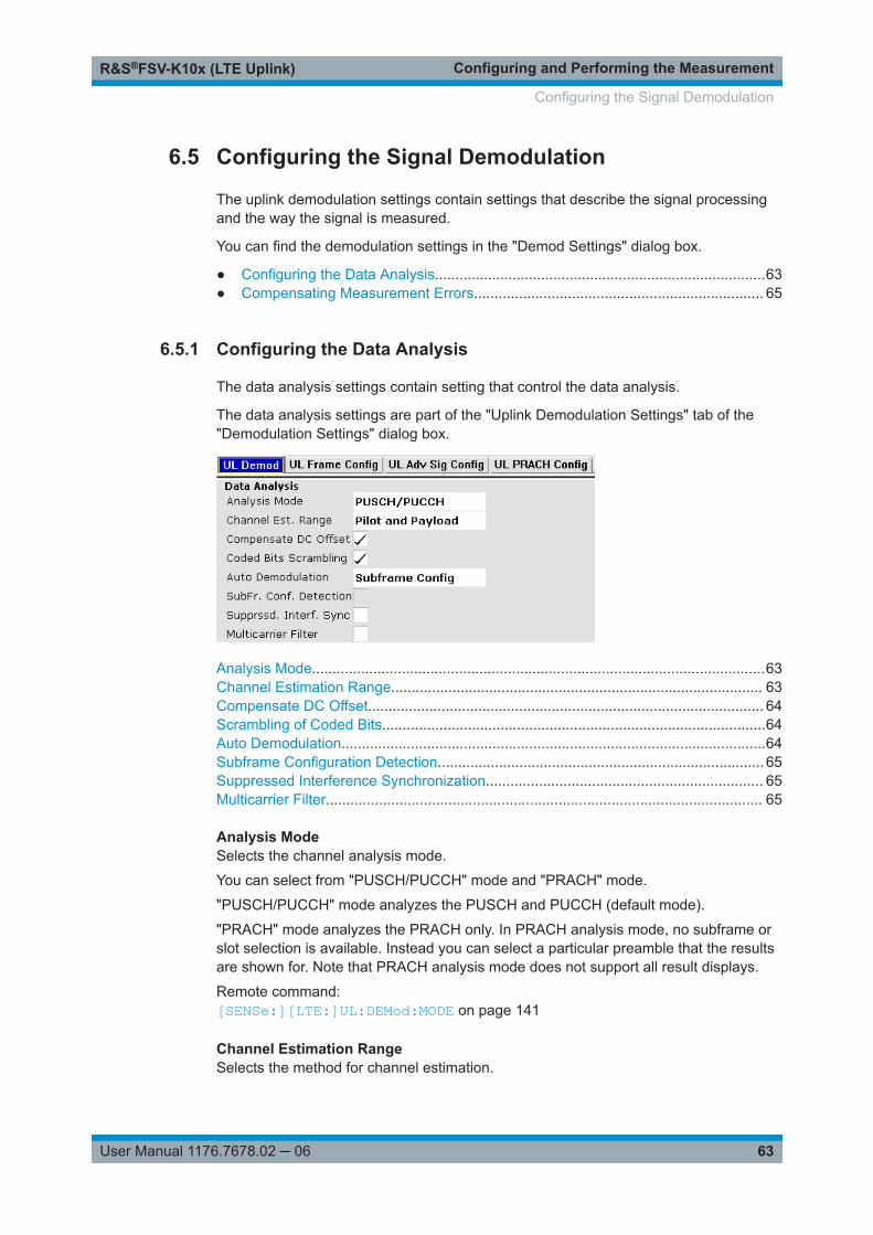
Configuring and Performing the MeasurementR&S®FSV-K10x (LTE Uplink)
63User Manual 1176.7678.02 ─ 06
6.5 Configuring the Signal Demodulation
The uplink demodulation settings contain settings that describe the signal processingand the way the signal is measured.
You can find the demodulation settings in the "Demod Settings" dialog box.
● Configuring the Data Analysis.................................................................................63● Compensating Measurement Errors....................................................................... 65
6.5.1 Configuring the Data Analysis
The data analysis settings contain setting that control the data analysis.
The data analysis settings are part of the "Uplink Demodulation Settings" tab of the"Demodulation Settings" dialog box.
Analysis Mode...............................................................................................................63Channel Estimation Range........................................................................................... 63Compensate DC Offset................................................................................................. 64Scrambling of Coded Bits..............................................................................................64Auto Demodulation........................................................................................................64Subframe Configuration Detection................................................................................ 65Suppressed Interference Synchronization.................................................................... 65Multicarrier Filter........................................................................................................... 65
Analysis ModeSelects the channel analysis mode.
You can select from "PUSCH/PUCCH" mode and "PRACH" mode.
"PUSCH/PUCCH" mode analyzes the PUSCH and PUCCH (default mode).
"PRACH" mode analyzes the PRACH only. In PRACH analysis mode, no subframe orslot selection is available. Instead you can select a particular preamble that the resultsare shown for. Note that PRACH analysis mode does not support all result displays.
Remote command: [SENSe:][LTE:]UL:DEMod:MODE on page 141
Channel Estimation RangeSelects the method for channel estimation.
Configuring the Signal Demodulation

Configuring and Performing the MeasurementR&S®FSV-K10x (LTE Uplink)
64User Manual 1176.7678.02 ─ 06
You can select if only the pilot symbols are used to perform channel estimation or ifboth pilot and payload carriers are used.
Remote command: [SENSe:][LTE:]UL:DEMod:CESTimation on page 140
Compensate DC OffsetTurns DC offset compensation when calculating measurement results on and off.
According to 3GPP TS 36.101 (Annex F.4), the R&S FSVA/FSV removes the carrierleakage (I/Q origin offset) from the evaluated signal before it calculates the EVM andin-band emissions.
Remote command: [SENSe:][LTE:]UL:DEMod:CDCoffset on page 140
Scrambling of Coded BitsTurns the scrambling of coded bits for the PUSCH on and off.
The scrambling of coded bits affects the bitstream results.
Scrambling Modulation mapper
Modulation mapper
codewords
Layer mapper
[...]
[...]
layers
=ON(unscrambled bits)
=OFF(scrambled bits)
Source of bitstream results when 'Scrambling of coded bits' is
Scrambling
Figure 6-1: Source for bitstream results if scrambling for coded bits is on and off
Remote command: [SENSe:][LTE:]UL:DEMod:CBSCrambling on page 140
Auto DemodulationTurns automatic demodulation on and off.
When you select "Predefined" mode, you can configure the subframe manually.
When you select "Auto" mode, the R&S FSVA/FSV automatically detects the charac-teristics of each subframe in the signal (resource allocation of the signal). Two methodsof detection are supported:● Subframe Configuration
This method automatically determines the characteristics for each subframe asshown in the Subframe Configuration Table.The table is populated accordingly.
● Subframe Configuration & DMRSAuto Demodulation, DMRS Auto Detection (On)This method automatically detects the PUSCH and SRS (i.e. no PUCCH can bedetected).
Configuring the Signal Demodulation

Configuring and Performing the MeasurementR&S®FSV-K10x (LTE Uplink)
65User Manual 1176.7678.02 ─ 06
To determine these characteristics, the software detects the CAZAC base parame-ters. Thus, the DMRS configuration parameters are not required for the synchroni-zation and therefore are not available using this method.Note however that it is not possible to derive the DMRS configuration parametersfrom the CAZAC base parameters so that the disabled DMRS configuration param-eters do not reflect the current parameters used for the synchronization. Also notethat it can happen that the software successfully synchronizes on non-3GPP sig-nals without a warning.
Automatic demodulation is not available if you suppress interferers for synchronizationis active.
Remote command: [SENSe:][LTE:]UL:DEMod:ACON on page 139
Subframe Configuration DetectionTurns the detection of the subframe configuration on and off.
When you select "Physical Detection", the R&S FSVA/FSV compares the currentlydemodulated LTE frame to the subframe configuration you have defined in the table.The application only analyzes the LTE frame if the signal is consistent with the configu-ration.
When you turn the feature "Off", the software analyzes the signal even if it is not con-sistent with the current subframe configuration.
Subframe configuration detection is available if you are using a Predefined subframeconfiguration.
Remote command: [SENSe:][LTE:]UL:FORMat:SCD on page 141
Suppressed Interference SynchronizationTurns suppressed interference synchronization on and off.
If active, the synchronization on signals containing more than one user equipment (UE)is more robust. Additionally, the EVM is lower in case the UEs have different frequencyoffsets. Note that Auto Demodulation is not supported in this synchronization modeand the EVM may be higher in case only one UE is present in the signal.
Remote command: [SENSe:][LTE:]UL:DEMod:SISYnc on page 141
Multicarrier FilterTurns the suppression of interference of neighboring carriers on and off.
Remote command: [SENSe:][LTE:]UL:DEMod:MCFilter on page 140
6.5.2 Compensating Measurement Errors
The tracking settings contain settings that compensate for various common measure-ment errors that may occur.
Configuring the Signal Demodulation

Configuring and Performing the MeasurementR&S®FSV-K10x (LTE Uplink)
66User Manual 1176.7678.02 ─ 06
The tracking settings are part of the "Uplink Demodulation Settings" tab of the "Demod-ulation Settings" dialog box.
Phase............................................................................................................................ 66Timing............................................................................................................................66
PhaseTurns phase tracking on and off.
When you turn on phase tracking, the application compensates the measurementresults for the phase error on a symbol level.
"Off" Phase tracking is not applied.
"Pilot Only" Only the reference signal is used for the estimation of the phaseerror.
"Pilot and Pay-load"
Both reference signal and payload resource elements are used forthe estimation of the phase error.
Remote command: [SENSe:][LTE:]UL:TRACking:PHASe on page 142
TimingTurns timing tracking on and off.
When you turn on timing tracking, the application compensates the measurementresults for the timing error on a symbol level.
Remote command: [SENSe:][LTE:]UL:TRACking:TIME on page 142
6.6 Configuring Uplink Frames
The frame configuration contains settings that define the structure of the uplink LTEsignal.
You can find the frame structure in the "Demod Settings" dialog box.
6.6.1 Configuring TDD Signals
The TDD settings define the characteristics of an LTE TDD signal.
The TDD settings are part of the "Frame Configuration" tab of the "Demodulation Set-tings" dialog box.
Configuring Uplink Frames

Configuring and Performing the MeasurementR&S®FSV-K10x (LTE Uplink)
67User Manual 1176.7678.02 ─ 06
Configuring TDD Frames.............................................................................................. 67└ TDD UL/DL Allocations...................................................................................67└ Conf. of Special Subframe..............................................................................67
Configuring TDD FramesTDD frames contain both uplink and downlink information separated in time with everysubframe being responsible for either uplink or downlink transmission. The standardspecifies several subframe configurations or resource allocations for TDD systems.
TDD UL/DL Allocations ← Configuring TDD FramesSelects the configuration of the subframes in a radio frame in TDD systems.
The UL/DL configuration (or allocation) defines the way each subframe is used: foruplink, downlink or if it is a special subframe. The standard specifies seven differentconfigurations.
ConfigurationSubframe Number and Usage
0 987654321
0
1
2
3
4
5
6
D
D
D
D
D
D
D
S
S
S
S
S
S
S
U
U
U
U
U
U
U
U
U
D
U
U
D
U
U
D
D
U
D
D
U
D
D
D
D
D
D
D
S
S
S
D
D
D
S
U
U
U
D
D
D
U
U
U
D
D
D
D
U
U
D
D
D
D
D
D
U = uplinkD = downlinkS = special subframe
Remote command: Subframe: CONFigure[:LTE]:UL[:CC<cc>]:TDD:UDConf on page 143
Conf. of Special Subframe ← Configuring TDD FramesIn combination with the cyclic prefix, the special subframes serve as guard periods forswitches from uplink to downlink. They contain three parts or fields.● DwPTS
The DwPTS is the downlink part of the special subframe. It is used to transmitdownlink data.
● GPThe guard period makes sure that there are no overlaps of up- and downlink sig-nals during a switch.
● UpPTSThe UpPTS is the uplink part of the special subframe. It is used to transmit uplinkdata.
Configuring Uplink Frames

Configuring and Performing the MeasurementR&S®FSV-K10x (LTE Uplink)
68User Manual 1176.7678.02 ─ 06
The length of the three fields is variable. This results in several possible configurationsof the special subframe. The LTE standard defines 10 different configurations for thespecial subframe. However, configurations 8 and 9 only work for a normal cyclic prefix.
If you select configurations 8 or 9 using an extended cyclic prefix or automatic detec-tion of the cyclic prefix, the application will show an error message.
Remote command: Special subframe: CONFigure[:LTE]:UL[:CC<cc>]:TDD:SPSC on page 143
6.6.2 Configuring the Physical Layer Cell Identity
The physical signal characteristics contain settings to describe the phyiscal attributesof an LTE signal.
The physical settings are part of the "Frame Configuration" tab of the "DemodulationSettings" dialog box.
Configuring the Physical Layer Cell Identity..................................................................68
Configuring the Physical Layer Cell IdentityThe "Cell ID", "Cell Identity Group" and physical layer "Identity" are interdependentparameters. In combination, they are responsible for synchronization between networkand user equipment.
The physical layer cell ID identifies a particular radio cell in the LTE network. The cellidentities are divided into 168 unique cell identity groups. Each group consists of 3physical layer identities. According to:
)2()1(3 IDIDcellID NNN
N(1) = cell identity group, {0...167}N(2) = physical layer identity, {0...2}
there is a total of 504 different cell IDs.
If you change one of these three parameters, the application automatically updates theother two.
The cell ID determines:● The reference signal grouping hopping pattern● The reference signal sequence hopping● The PUSCH demodulation reference signal pseudo-random sequence● The cyclic shifts for PUCCH formats 1/1a/1b and sequences for PUCCH formats
2/2a/2b● The pseudo-random sequence used for scrambling● The pseudo-random sequence used for type 2 PUSCH frequency hopping
Configuring Uplink Frames

Configuring and Performing the MeasurementR&S®FSV-K10x (LTE Uplink)
69User Manual 1176.7678.02 ─ 06
It is possible to select a separate "Identity" for Demodulation Reference Signal,PUSCH and PUCCH allocations from the "Identity" property in the "Advanced SignalCharacteristics". When you select "From Cell ID", the "Identity" for the DMRS, PUSCHand PUCCH is the same as the Cell ID.
Remote command: Cell ID: CONFigure[:LTE]:UL[:CC<cc>]:PLC:CID on page 144Cell Identity Group: CONFigure[:LTE]:UL[:CC<cc>]:PLC:CIDGroupon page 144Identity: CONFigure[:LTE]:UL[:CC<cc>]:PLC:PLID on page 144
6.6.3 Subframe Configuration
An LTE frame consists of 10 subframes. Each individual subframe can have a differentresource block configuration. This configuration is shown in the "Subframe Configura-tion Table".
The application supports two ways to determine the characteristics of each subframe.● Automatic demodulation of the channel configuration and detection of the subframe
characteristics.For automatic demodulation, the contents of the table are determined according tothe signal currently evaluated.For more information, see "Auto Demodulation" on page 64.
● Custom configuration of the configuration of each subframe.Remote command:Conf. subframes: CONFigure[:LTE]:UL[:CC<cc>]:CSUBframes on page 145
Frame number offset
A frame number offset is also available. The frame number offset assigns a number tothe demodulated frame in order to identify it in a series of transmitted (and captured)frames.
Remote command:
CONFigure[:LTE]:UL[:CC<cc>]:SFNO on page 145
● Individual Subframe Configuration..........................................................................69
6.6.3.1 Individual Subframe Configuration
The "Subframe Configuration Table" contains the characteristics for each subframe.The software supports a maximum uplink LTE frame size of 10 subframes. The sub-frame number in the table depends on the number of "Configurable Subframes" thatyou have defined or that have been detected for automatic demodulation.
Configuring Uplink Frames
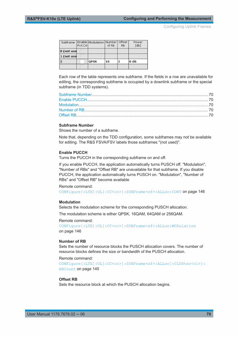
Configuring and Performing the MeasurementR&S®FSV-K10x (LTE Uplink)
70User Manual 1176.7678.02 ─ 06
Each row of the table represents one subframe. If the fields in a row are unavailable forediting, the corresponding subframe is occupied by a downlink subframe or the specialsubframe (in TDD systems).
Subframe Number.........................................................................................................70Enable PUCCH............................................................................................................. 70Modulation.....................................................................................................................70Number of RB............................................................................................................... 70Offset RB.......................................................................................................................70
Subframe NumberShows the number of a subframe.
Note that, depending on the TDD configuration, some subframes may not be availablefor editing. The R&S FSVA/FSV labels those subframes "(not used)".
Enable PUCCHTurns the PUCCH in the corresponding subframe on and off.
If you enable PUCCH, the application automatically turns PUSCH off. "Modulation","Number of RBs" and "Offset RB" are unavailable for that subframe. If you disablePUCCH, the application automatically turns PUSCH on. "Modulation", "Number ofRBs" and "Offset RB" become available
Remote command: CONFigure[:LTE]:UL[:CC<cc>]:SUBFrame<sf>:ALLoc:CONT on page 146
ModulationSelects the modulation scheme for the corresponding PUSCH allocation.
The modulation scheme is either QPSK, 16QAM, 64QAM or 256QAM.
Remote command: CONFigure[:LTE]:UL[:CC<cc>]:SUBFrame<sf>:ALLoc:MODulationon page 146
Number of RBSets the number of resource blocks the PUSCH allocation covers. The number ofresource blocks defines the size or bandwidth of the PUSCH allocation.
Remote command: CONFigure[:LTE]:UL[:CC<cc>]:SUBFrame<sf>:ALLoc[:CLUSter<cl>]:RBCount on page 145
Offset RBSets the resource block at which the PUSCH allocation begins.
Configuring Uplink Frames
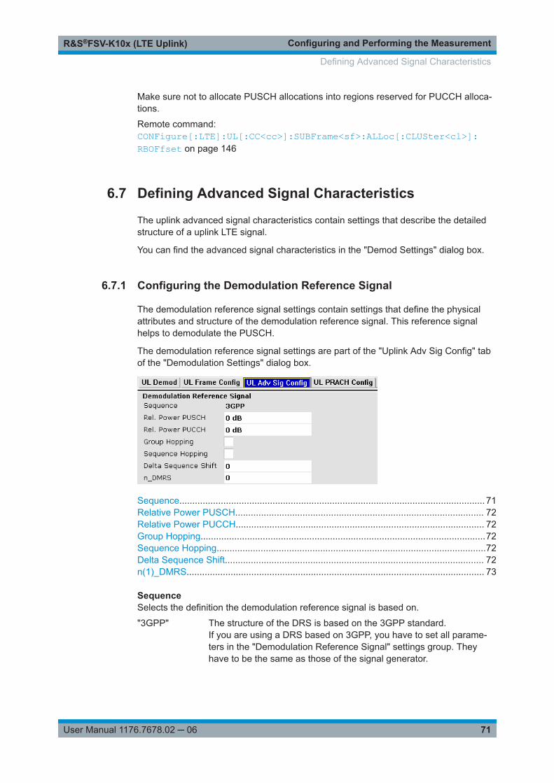
Configuring and Performing the MeasurementR&S®FSV-K10x (LTE Uplink)
71User Manual 1176.7678.02 ─ 06
Make sure not to allocate PUSCH allocations into regions reserved for PUCCH alloca-tions.
Remote command: CONFigure[:LTE]:UL[:CC<cc>]:SUBFrame<sf>:ALLoc[:CLUSter<cl>]:RBOFfset on page 146
6.7 Defining Advanced Signal Characteristics
The uplink advanced signal characteristics contain settings that describe the detailedstructure of a uplink LTE signal.
You can find the advanced signal characteristics in the "Demod Settings" dialog box.
6.7.1 Configuring the Demodulation Reference Signal
The demodulation reference signal settings contain settings that define the physicalattributes and structure of the demodulation reference signal. This reference signalhelps to demodulate the PUSCH.
The demodulation reference signal settings are part of the "Uplink Adv Sig Config" tabof the "Demodulation Settings" dialog box.
Sequence...................................................................................................................... 71Relative Power PUSCH................................................................................................ 72Relative Power PUCCH................................................................................................ 72Group Hopping..............................................................................................................72Sequence Hopping........................................................................................................72Delta Sequence Shift.................................................................................................... 72n(1)_DMRS................................................................................................................... 73
SequenceSelects the definition the demodulation reference signal is based on.
"3GPP" The structure of the DRS is based on the 3GPP standard.If you are using a DRS based on 3GPP, you have to set all parame-ters in the "Demodulation Reference Signal" settings group. Theyhave to be the same as those of the signal generator.
Defining Advanced Signal Characteristics

Configuring and Performing the MeasurementR&S®FSV-K10x (LTE Uplink)
72User Manual 1176.7678.02 ─ 06
Relative Power PUSCHDefines the power of the DMRS relative to the power level of the PUSCH allocation inthe corresponding subframe (PDMRS_Offset).
The effective power level of the DMRS depends on the allocation of the subframe andis calculated as follows.
PDMRS = PUE + PPUSCH + PDMRS_Offset
The relative power of the DMRS is applied to all subframes.
The power of the PUSCH (PPUSCH) may be different in each subframe.
Remote command: CONFigure[:LTE]:UL[:CC<cc>]:DRS[:PUSCh]:POWer on page 148
Relative Power PUCCHDefines the power of the DMRS relative to the power level of the PUCCH allocation inthe corresponding subframe (PDMRS_Offset).
The effective power level of the DMRS depends on the allocation of the subframe andis calculated as follows.
PDMRS = PUE + PPUCCH + PDMRS_Offset
The relative power of the DMRS is applied to all subframes.
The power of the PUCCH (PPUCCH) may be different in each subframe.
Remote command: CONFigure[:LTE]:UL[:CC<cc>]:DRS:PUCCh:POWer on page 148
Group HoppingTurns group hopping for the demodulation reference signal on and off.
The group hopping pattern is based on 17 hopping patterns and 30 sequence shift pat-terns. It is generated by a pseudo-random sequence generator.
If on, PUSCH and PUCCH use the same group hopping pattern.
Remote command: CONFigure[:LTE]:UL[:CC<cc>]:DRS:GRPHopping on page 147
Sequence HoppingTurns sequence hopping for the uplink demodulation reference signal on and off.
Sequence hopping is generated by a pseudo-random sequence generator.
Remote command: CONFigure[:LTE]:UL[:CC<cc>]:DRS:SEQHopping on page 149
Delta Sequence ShiftDefines the delta sequence shift ΔSS.
The standard defines a sequence shift pattern fss for the PUCCH. The correspondingsequence shift pattern for the PUSCH is a function of fss
PUCCH and the delta sequenceshift.
For more information refer to 3GPP TS 36.211, chapter 5.5.1.3 "Group Hopping".
Defining Advanced Signal Characteristics

Configuring and Performing the MeasurementR&S®FSV-K10x (LTE Uplink)
73User Manual 1176.7678.02 ─ 06
Remote command: CONFigure[:LTE]:UL[:CC<cc>]:DRS:DSSHift on page 147
n(1)_DMRSThe n_DMRS parameter can be found in 3GPP TS36.211 V8.5.0, 5.5.2.1.1 Referencesignal sequence.
Currently, n_DMRS is defined as n_DMRS = nDMRS(1)+nDMRS
(2) .
Remote command: CONFigure[:LTE]:UL[:CC<cc>]:DRS:NDMRs on page 148
6.7.2 Configuring the Sounding Reference Signal
The sounding reference signal settings contain settings that define the physical attrib-utes and structure of the sounding reference signal.
The sounding reference signal settings are part of the "Uplink Adv Sig Config" tab ofthe "Demodulation Settings" dialog box.
Present..........................................................................................................................73SRS Rel Power............................................................................................................. 74SRS Subframe Configuration........................................................................................74SRS Bandwidth B_SRS................................................................................................ 74Freq. Domain Pos. n_RRC........................................................................................... 74SRS BW Conf. C_SRS................................................................................................. 74Transm. Comb. k_TC....................................................................................................75SRS Cyclic Shift N_CS................................................................................................. 75Conf. Index I_SRS........................................................................................................ 75Hopping BW b_hop....................................................................................................... 75
PresentIncludes or excludes the sounding reference signal (SRS) from the test setup.
Remote command: CONFigure[:LTE]:UL[:CC<cc>]:SRS:STAT on page 151
Defining Advanced Signal Characteristics

Configuring and Performing the MeasurementR&S®FSV-K10x (LTE Uplink)
74User Manual 1176.7678.02 ─ 06
SRS Rel PowerDefines the power of the SRS relative to the power of the corresponding UE (PSRS_Off-
set).
The effective power level of the SRS is calculated as follows.
PSRS = PUE + PSRS_Offset
The relative power of the SRS is applied to all subframes.
Remote command: CONFigure[:LTE]:UL[:CC<cc>]:SRS:POWer on page 151
SRS Subframe ConfigurationDefines the subframe configuration of the SRS.
The subframe configuration of the SRS is specific to a cell. The UE sends a shortenedPUCCH/PUSCH in these subframes, regardless of whether the UE is configured tosend an SRS in the corresponding subframe or not.
Remote command: CONFigure[:LTE]:UL[:CC<cc>]:SRS:SUConfig on page 152
SRS Bandwidth B_SRSDefines the parameter BSRS.
BSRS is a UE specific parameter that defines the bandwidth of the SRS. The SRS eitherspans the entire frequency bandwidth or uses frequency hopping when several narrow-band SRS cover the same total bandwidth.
The standard defines up to four bandwidths for the SRS. The most narrow SRS band-width (BSRS = 3) spans four resource blocks and is available for all channel bandwidths.The other three values of BSRS define more wideband SRS bandwidths. Their availabil-ity depends on the channel bandwidth.
The availability of SRS bandwidths additionally depends on the bandwidth configura-tion of the SRS (CSRS).
For more information refer to 3GPP TS 36.211, chapter 5.5.3.2 "Mapping to PhysicalResources" for the Sounding Reference Signal.
Remote command: CONFigure[:LTE]:UL[:CC<cc>]:SRS:BSRS on page 149
Freq. Domain Pos. n_RRCDefines the parameter nRRC.
nRRC is a UE specific parameter and determines the starting physical resource block ofthe SRS transmission.
For more information refer to 3GPP TS 36.211, chapter 5.5.3.2 "Mapping to PhysicalResources" for the Sounding Reference Signal.
Remote command: CONFigure[:LTE]:UL[:CC<cc>]:SRS:NRRC on page 151
SRS BW Conf. C_SRSDefines the bandwidth configuration of the SRS.
Defining Advanced Signal Characteristics

Configuring and Performing the MeasurementR&S®FSV-K10x (LTE Uplink)
75User Manual 1176.7678.02 ─ 06
The bandwidth configuration is a cell-specific parameter that, in combination with theSRS bandwidth and the channel bandwidth, defines the length of the sounding refer-ence signal sequence. For more information on the calculation, refer to 3GPP TS36.211 chapter 5.5.3 "Sounding Reference Signal".
Remote command: CONFigure[:LTE]:UL[:CC<cc>]:SRS:CSRS on page 150
Transm. Comb. k_TCDefines the transmission comb kTC.
The transmission comb. is a UE specific parameter. For more information refer to3GPP TS 36.211, chapter 5.5.3.2 "Mapping to Physical Resources" for the SoundingReference Signal.
Remote command: CONFigure[:LTE]:UL[:CC<cc>]:SRS:TRComb on page 152
SRS Cyclic Shift N_CSDefines the cyclic shift (nCS) used for the generation of the SRS CAZAC sequence.
Because the different shifts of the same Zadoff-Chu sequence are orthogonal to eachother, applying different SRS cyclic shifts can be used to schedule different UE tosimultaneously transmit their SRS.
Remote command: CONFigure[:LTE]:UL[:CC<cc>]:SRS:CYCS on page 150
Conf. Index I_SRSDefines the configuration index of the SRS.
The configuration index ISRS is a cell specific parameter that determines the SRS perio-dicity (TSRS) and the SRS subframe offset (Toffset). The effects of the configuration indexon TSRS and Toffset depends on the duplexing mode.
For more information refer to 3GPP TS 36.213, Table 8.2-1 (FDD) and 8.2-2 (TDD).
Remote command: CONFigure[:LTE]:UL[:CC<cc>]:SRS:ISRS on page 150
Hopping BW b_hopDefines the parameter bhop.
bhop is a UE specific parameter that defines the frequency hopping bandwidth. SRS fre-quency hopping is active if bhop < BSRS.
For more information refer to 3GPP TS 36.211, chapter 5.5.3.2 "Mapping to PhysicalResources" for the Sounding Reference Signal.
Remote command: CONFigure[:LTE]:UL[:CC<cc>]:SRS:BHOP on page 149
Defining Advanced Signal Characteristics

Configuring and Performing the MeasurementR&S®FSV-K10x (LTE Uplink)
76User Manual 1176.7678.02 ─ 06
6.7.3 Defining the PUSCH Structure
The PUSCH structure settings contain settings that describe the physical attributes andstructure of the PUSCH.
The PUSCH structure is part of the "Uplink Adv Sig Config" tab of the "DemodulationSettings" dialog box.
Frequency Hopping Mode.............................................................................................76PUSCH Hopping Offset.................................................................................................76Number of Subbands.................................................................................................... 76Info. in Hopping Bits...................................................................................................... 77
Frequency Hopping ModeSelects the frequency hopping mode of the PUSCH.
Several hopping modes are supported.● None
No frequency hopping.● Inter Subframe Hopping
PUSCH changes the frequency from one subframe to another.● Intra Subframe Hopping
PUSCH also changes the frequency within a subframe.
Remote command: CONFigure[:LTE]:UL[:CC<cc>]:PUSCh:FHMode on page 152
PUSCH Hopping OffsetDefines the PUSCH Hopping Offset NRB
HO.
The PUSCH Hopping Offset determines the first physical resource block and the maxi-mum number of physical resource blocks available for PUSCH transmission if PUSCHfrequency hopping is active.
Remote command: CONFigure[:LTE]:UL[:CC<cc>]:PUSCh:FHOFfset on page 153
Number of SubbandsDefines the number of subbands reserved for PUSCH.
For more information refer to 3GPP TS 36.211, chapter 5.5.3.2 "Mapping to PhysicalResources" for the Sounding Reference Signal.
Remote command: CONFigure[:LTE]:UL[:CC<cc>]:PUSCh:NOSM on page 153
Defining Advanced Signal Characteristics
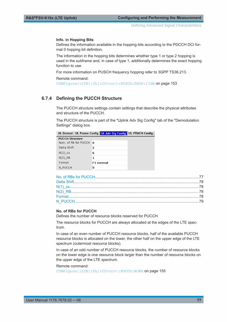
Configuring and Performing the MeasurementR&S®FSV-K10x (LTE Uplink)
77User Manual 1176.7678.02 ─ 06
Info. in Hopping BitsDefines the information available in the hopping bits according to the PDCCH DCI for-mat 0 hopping bit definition.
The information in the hopping bits determines whether type 1 or type 2 hopping isused in the subframe and, in case of type 1, additionally determines the exact hoppingfunction to use.
For more information on PUSCH frequency hopping refer to 3GPP TS36.213.
Remote command: CONFigure[:LTE]:UL[:CC<cc>]:PUSCh:FHOP:IIHB on page 153
6.7.4 Defining the PUCCH Structure
The PUCCH structure settings contain settings that describe the physical attributesand structure of the PUCCH.
The PUCCH structure is part of the "Uplink Adv Sig Config" tab of the "DemodulationSettings" dialog box.
No. of RBs for PUCCH..................................................................................................77Delta Shift......................................................................................................................78N(1)_cs..........................................................................................................................78N(2)_RB........................................................................................................................ 78Format...........................................................................................................................78N_PUCCH.....................................................................................................................79
No. of RBs for PUCCHDefines the number of resource blocks reserved for PUCCH.
The resource blocks for PUCCH are always allocated at the edges of the LTE spec-trum.
In case of an even number of PUCCH resource blocks, half of the available PUCCHresource blocks is allocated on the lower, the other half on the upper edge of the LTEspectrum (outermost resource blocks).
In case of an odd number of PUCCH resource blocks, the number of resource blockson the lower edge is one resource block larger than the number of resource blocks onthe upper edge of the LTE spectrum.
Remote command: CONFigure[:LTE]:UL[:CC<cc>]:PUCCh:NORB on page 155
Defining Advanced Signal Characteristics

Configuring and Performing the MeasurementR&S®FSV-K10x (LTE Uplink)
78User Manual 1176.7678.02 ─ 06
Delta ShiftDefines the delta shift parameter.
The delta shift is the difference between two adjacent PUCCH resource indices withthe same orthogonal cover sequence (OC).
It determines the number of available sequences in a resource block that can be usedfor PUCCH formats 1/1a/1b.
For more information refer to 3GPP TS36.211, chapter 5.4 "Physical Uplink ControlChannel".
Remote command: CONFigure[:LTE]:UL[:CC<cc>]:PUCCh:DESHift on page 154
N(1)_csDefines the number of cyclic shifts used for PUCCH format 1/1a/1b in a resource blockused for a combination of the formats 1/1a/1b and 2/2a/2b.
Only one resource block per slot can support a combination of the PUCCH formats1/1a/1b and 2/2a/2b.
The number of cyclic shifts available for PUCCH format 2/2a/2b N(2)_cs in a block withcombination of PUCCH formats is calculated as follows.
N(2)_cs = 12 - N(1)_cs - 2
For more information refer to 3GPP TS36.211, chapter 5.4 "Physical Uplink ControlChannel".
Remote command: CONFigure[:LTE]:UL[:CC<cc>]:PUCCh:N1CS on page 155
N(2)_RBDefines bandwidth in terms of resource blocks that are reserved for PUCCH formats2/2a/2b transmission in each subframe.
Since there can be only one resource block per slot that supports a combination of thePUCCH formats 1/1a/1b and 2/2a/2b, the number of resource block(s) per slot availa-ble for PUCCH format 1/1a/1b is determined by N(2)_RB.
For more information refer to 3GPP TS36.211, chapter 5.4 "Physical Uplink ControlChannel".
Remote command: CONFigure[:LTE]:UL[:CC<cc>]:PUCCh:N2RB on page 155
FormatSelects the format of the PUCCH.
You can define the PUCCH format for all subframes or define the PUCCH format foreach subframe individually.● F1, F1a, F1b, F2, F2a, F2b, F3
Selects the PUCCH format globally for every subframe.Note that formats F2a and F2b are only supported for normal cyclic prefix length.
For more information refer to 3GPP TS36.211, table 5.4-1 "Supported PUCCH For-mats".
Defining Advanced Signal Characteristics

Configuring and Performing the MeasurementR&S®FSV-K10x (LTE Uplink)
79User Manual 1176.7678.02 ─ 06
Remote command: CONFigure[:LTE]:UL[:CC<cc>]:PUCCh:FORMat on page 154
N_PUCCHDefines the resource index for PUCCH format 1/1a/1b respectively 2/2a/2b.
It is also possible to define NPUCCH on a subframe level by selecting the "Per Subframe"menu item. For more information see Chapter 6.6.3, "Subframe Configuration",on page 69.
Remote command: CONFigure[:LTE]:UL[:CC<cc>]:PUCCh:NPAR on page 156
6.7.5 Defining Global Signal Characteristics
The global settings contain settings that apply to the complete signal.
The global settings are part of the "Uplink Adv Sig Config" tab of the "DemodulationSettings" dialog box.
UE ID/n_RNTI............................................................................................................... 79
UE ID/n_RNTISets the radio network temporary identifier (RNTI) of the UE.
Remote command: CONFigure[:LTE]:UL[:CC<cc>]:UEID on page 156
6.8 Defining the PRACH Structure
The PRACH structure settings contain settings that describe the physical attributes andstructure of the PRACH.
The PRACH structure setup is part of the "Uplink PRACH Config" tab of the "Demodu-lation Settings" dialog box.
Defining the PRACH Structure
Configuring and Performing the MeasurementR&S®FSV-K10x (LTE Uplink)
80User Manual 1176.7678.02 ─ 06
PRACH Configuration................................................................................................... 80Restricted Set................................................................................................................80Frequency Offset...........................................................................................................80Ncs Conf....................................................................................................................... 80Logical Root Sequ. Idx.................................................................................................. 80Sequence Index (v)....................................................................................................... 80PRACH Preamble Mapping.......................................................................................... 81
PRACH ConfigurationSets the PRACH configuration index as defined in the 3GPP TS 36.211, i.e. definesthe subframes in which random access preamble transmission is allowed.
The preamble format is automatically derived from the PRACH Configuration.
Remote command: CONFigure[:LTE]:UL[:CC<cc>]:PRACh:CONF on page 157
Restricted SetSelects whether a restricted preamble set (high speed mode) or the unrestricted pre-amble set (normal mode) will be used.
Remote command: CONFigure[:LTE]:UL[:CC<cc>]:PRACh:RSET on page 159
Frequency OffsetThe "Frequency Offset" defines the PRACH frequency offset for preamble formats 0 to3 as defined in the 3GPP TS 36.211. The frequency offset determines the first physicalresource block available for PRACH expressed as a physical resource block number.
Remote command: CONFigure[:LTE]:UL[:CC<cc>]:PRACh:FOFFset on page 157
Ncs ConfSelects the Ncs configuration, i.e. determines the Ncs value set according to TS36.211, table 5.7.2.-2 and 5.7.2-3.
Remote command: CONFigure[:LTE]:UL[:CC<cc>]:PRACh:NCSC on page 158
Logical Root Sequ. IdxSelects the logical root sequence index.
The logical root sequence index is used to generate preamble sequences. It is provi-ded by higher layers.
Remote command: CONFigure[:LTE]:UL[:CC<cc>]:PRACh:RSEQ on page 158
Sequence Index (v)Defines the sequence index (v).
The sequence index controls which of the 64 preambles available in a cell is used.
If you select the "Auto" menu item, the software automatically selects the requiredsequence index.
Defining the PRACH Structure

Configuring and Performing the MeasurementR&S®FSV-K10x (LTE Uplink)
81User Manual 1176.7678.02 ─ 06
Remote command: CONFigure[:LTE]:UL[:CC<cc>]:PRACh:SINDex on page 159
PRACH Preamble MappingThe frequency resource index fRA and the half frame indicator t1RA are necessary forclear specification of the physical resource mapping of the PRACH, in case a PRACHconfiguration index has more than one mapping alternative.
If you turn on the "Auto Preamble Mapping", the R&S FSVA/FSV automatically detectsfRA and t1RA.
The values for both parameters are defined in table '5.7.1-4: Frame structure type 2random access preamble mapping in time and frequency' (3GPP TS 36.211 v10.2.0).
The frequency resource index and half frame indicator are available in TDD mode.
Remote command: CONFigure[:LTE]:UL[:CC<cc>]:PRACh:APM on page 157CONFigure[:LTE]:UL[:CC<cc>]:PRACh:FRINdex on page 157CONFigure[:LTE]:UL[:CC<cc>]:PRACh:HFINdicator on page 158
Defining the PRACH Structure
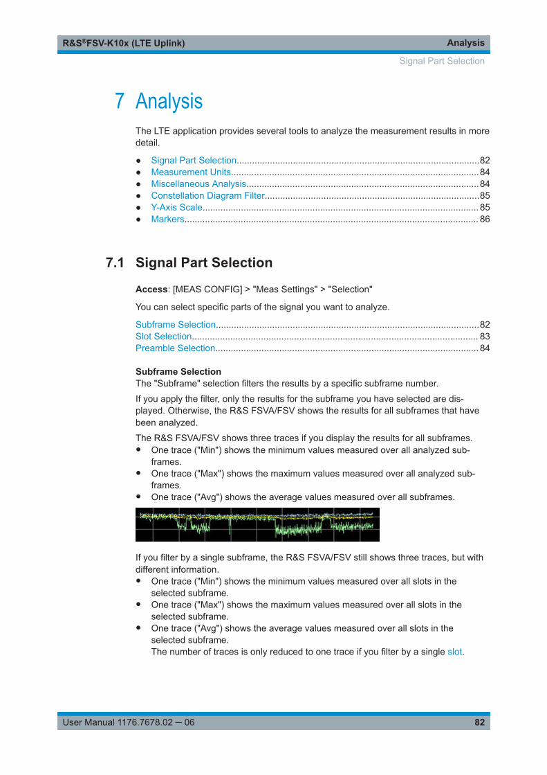
AnalysisR&S®FSV-K10x (LTE Uplink)
82User Manual 1176.7678.02 ─ 06
7 AnalysisThe LTE application provides several tools to analyze the measurement results in moredetail.
● Signal Part Selection...............................................................................................82● Measurement Units.................................................................................................84● Miscellaneous Analysis...........................................................................................84● Constellation Diagram Filter....................................................................................85● Y-Axis Scale............................................................................................................ 85● Markers................................................................................................................... 86
7.1 Signal Part Selection
Access: [MEAS CONFIG] > "Meas Settings" > "Selection"
You can select specific parts of the signal you want to analyze.
Subframe Selection.......................................................................................................82Slot Selection................................................................................................................ 83Preamble Selection....................................................................................................... 84
Subframe SelectionThe "Subframe" selection filters the results by a specific subframe number.
If you apply the filter, only the results for the subframe you have selected are dis-played. Otherwise, the R&S FSVA/FSV shows the results for all subframes that havebeen analyzed.
The R&S FSVA/FSV shows three traces if you display the results for all subframes.● One trace ("Min") shows the minimum values measured over all analyzed sub-
frames.● One trace ("Max") shows the maximum values measured over all analyzed sub-
frames.● One trace ("Avg") shows the average values measured over all subframes.
If you filter by a single subframe, the R&S FSVA/FSV still shows three traces, but withdifferent information.● One trace ("Min") shows the minimum values measured over all slots in the
selected subframe.● One trace ("Max") shows the maximum values measured over all slots in the
selected subframe.● One trace ("Avg") shows the average values measured over all slots in the
selected subframe.The number of traces is only reduced to one trace if you filter by a single slot.
Signal Part Selection

AnalysisR&S®FSV-K10x (LTE Uplink)
83User Manual 1176.7678.02 ─ 06
In PRACH analysis mode, you cannot filter by a single subframe.
You can apply the filter to the following result displays.● Result Summary● EVM vs Carrier / EVM vs Symbol / EVM vs Symbol X Carrier● Spectrum Flatness / Spectrum Flatness SRS / Spectrum Flatness Difference● Inband Emission● Group Delay● Power vs Symbol X Carrier● Constellation Diagram● DFT Precoded Constellation● Allocation Summary● Bit Stream● Time Alignment Error
Remote command: [SENSe:][LTE:][CC<cc>:]SUBFrame:SELect on page 162
Slot SelectionThe "Slot" selection filters the results by a specific slot number.
If you apply the filter, only the results for the slot you have selected are displayed. Oth-erwise, the R&S FSVA/FSV shows the results for all slots.
The R&S FSVA/FSV shows three traces if you display the results for all slots.● One trace ("Min") shows the minimum values measured over all slots.● One trace ("Max") shows the maximum values measured over all slots.● One trace ("Avg") shows the average values measured over all slots.
If you filter by a single slot, the R&S FSVA/FSV shows one trace that represents thevalues measured for that slot only.
In PRACH analysis mode, you cannot filter by a single slot.
You can apply the filter to the following result displays.● Result Summary● EVM vs Carrier / EVM vs Symbol / EVM vs Symbol X Carrier● Inband Emission● Spectrum Flatness / Spectrum Flatness Difference● Group Delay● Power vs Symbol X Carrier● Constellation Diagram
Signal Part Selection

AnalysisR&S®FSV-K10x (LTE Uplink)
84User Manual 1176.7678.02 ─ 06
Remote command: [SENSe:][LTE:][CC<cc>:]SLOT:SELect on page 161
Preamble SelectionSelects a particular preamble for measurements that analyze individual preambles.
Selecting preambles is available in PRACH analysis mode.
Remote command: [SENSe:][LTE:][CC<cc>:]PREamble:SELect on page 161
7.2 Measurement Units
Access: [MEAS CONFIG] > "Meas Settings" > "Units"
You can select the unit for various measurements and result displays.
EVM Unit....................................................................................................................... 84
EVM UnitThe "EVM Unit" selects the unit for the EVM measurement results in diagrams andnumerical result displays.
Possible units are dB and %.
Remote command: UNIT:EVM on page 163
7.3 Miscellaneous Analysis
Access: [MEAS CONFIG] > "Meas Settings" > "Misc"
Bit Stream Format......................................................................................................... 84
Bit Stream FormatSelects the way the bit stream is displayed.
The bit stream is either a stream of raw bits or of symbols. In case of the symbol for-mat, the bits that belong to a symbol are shown as hexadecimal numbers with two dig-its.
Examples:
Figure 7-1: Bit stream display in uplink application if the bit stream format is set to "symbols"
Miscellaneous Analysis

AnalysisR&S®FSV-K10x (LTE Uplink)
85User Manual 1176.7678.02 ─ 06
Figure 7-2: Bit stream display in uplink application if the bit stream format is set to "bits"
Remote command: UNIT:BSTR on page 163
7.4 Constellation Diagram Filter
Access: [MEAS CONFIG] > "Constell" > "Constell Filter"
The evaluation filter selects the contents of the constellation diagram.
Evaluation range for the constellation diagram............................................................. 85
Evaluation range for the constellation diagramThe "Evaluation Range" for the constellation diagram selects the information displayedin the constellation diagram.
By default, the constellation diagram contains the constellation points of the completedata that has been analyzed. However, you can filter the results by several aspects.● Modulation
Filters the results by the selected type of modulation.● Allocation
Filters the results by a certain type of allocation.● Symbol (OFDM)
Filters the results by a certain OFDM symbol.● Carrier
Filters the results by a certain subcarrier.
Remote command: Modulation: [SENSe:][LTE:][CC<cc>:]MODulation:SELect on page 160Allocation: [SENSe:][LTE:][CC<cc>:]ALLocation:SELect on page 160Symbol: [SENSe:][LTE:][CC<cc>:]SYMBol:SELect on page 162Carrier: [SENSe:][LTE:][CC<cc>:]CARRier:SELect on page 160
7.5 Y-Axis Scale
Access: [MEAS CONFIG] > "Meas Settings" > "Y-Axis"
You can define the scale of the y-axis in most result displays.
Y-Axis Scale

AnalysisR&S®FSV-K10x (LTE Uplink)
86User Manual 1176.7678.02 ─ 06
Y-Axis Scale.................................................................................................................. 86
Y-Axis ScaleThe y-axis scaling determines the vertical resolution of the measurement results. Thescaling you select always applies to the currently active screen and the correspondingresult display.
Usually, the best way to view the results is if they fit ideally in the diagram area anddisplay the complete trace. This is the way the application scales the y-axis if you haveturned on automatic scaling.
But it can become necessary to see a more detailed version of the results. In that case,turn on fixed scaling for the y-axis. Fixed scaling becomes available when you turn offautomatic scaling. For a fixed scaling, define the distance between two grid lines (scal-ing per division) and the point of origin of the y-axis (the offset).Remote command: Automatic scaling:DISPlay[:WINDow]:TRACe:Y:SCALe:AUTO on page 168Manual scaling:DISPlay[:WINDow]:TRACe:Y:SCALe:FIXScale:OFFSet on page 169DISPlay[:WINDow]:TRACe:Y:SCALe:FIXScale:PERDiv on page 169
7.6 Markers
Access: [MKR]
Access: [MKR ➙]
The firmware application provides marker functionality to work with. You can use amarker to mark specific points on traces or to read out measurement results.
Markers

AnalysisR&S®FSV-K10x (LTE Uplink)
87User Manual 1176.7678.02 ─ 06
Figure 7-3: Example: Marker
The [MKR] key opens the corresponding submenu. You can activate up to four markerswith the "Marker <x>" softkeys. The first marker is always a normal marker. Markers 2to 4 are delta marker by default. The reference marker for the delta marker is marker 1.You can turn all delta markers into normal markers with the "Marker (Norm Delta)" soft-key.
After pressing the "Marker <x>" softkey, you can set the position of the marker in sev-eral ways.● Enter a frequency value in the marker input field.● Move the marker with the rotary knob.● Position the marker to the trace minimum or trace maximum with the "Marker Max"
or "Marker Min" softkeys.
The current marker frequency and the corresponding level is displayed in the upperright corner of the trace display.
The "Marker <x>" softkey have three possible states:● If the "Marker <x>" softkey is black, the marker is off.
● After pressing the "Marker <x>" softkey it turns orange to indicate an open dialogbox and the the marker is active. The dialog box to specify the marker position onthe frequency axis opens.
● After closing the dialog box, the "Marker <x>" softkey turns blue. The marker staysactive.
Markers

AnalysisR&S®FSV-K10x (LTE Uplink)
88User Manual 1176.7678.02 ─ 06
Pressing the "Marker <x>" softkey again deactivates the marker. You can also turnoff the marker by pressing the "All Marker Off" softkey.
If you'd like to see the area of the spectrum around the marker in more detail, you canuse the Marker Zoom function. Press the "Marker Zoom" softkey to open a dialog boxin which you can specify the zoom factor. The maximum possible zoom factor dependson the result display. The "Unzoom" softkey cancels the marker zoom.
Note that the zoom function is not available for all result displays.
If you have more than one active trace, it is possible to assign the marker to a specifictrace. Press the "Marker ➙ Trace" softkey in the marker to menu and specify the tracein the corresponding dialog box.
SCPI commands:
See Chapter 9.15.4, "Using Delta Markers", on page 166.
Markers

File ManagementR&S®FSV-K10x (LTE Uplink)
89User Manual 1176.7678.02 ─ 06
8 File Management● File Manager........................................................................................................... 89● SAVE/RECALL Key.................................................................................................90
8.1 File Manager
The root menu of the application includes a File Manager with limited functions forquick access to file management functionality.
Loading a Frame Setup
The frame setup or frame description describes the complete modulation structure ofthe signal, such as bandwidth, modulation, etc.
The frame setup is stored as an XML file. XML files are very commonly used todescribe hierarchical structures in an easy-to-read format for both humans and PC.
A typical frame setup file would look like this:
<FrameDefinition LinkDirection="uplink" TDDULDLAllocationConfiguration="0"RessourceBlocks="50" CP="auto" PhysLayCellIDGrp="Group 0" PhysLayID="ID 0"N_RNTI="0" N_f="0" NOfSubbands="4" N_RB_HO="4" NOfRB_PUCCH="4"DeltaShift="2" N1_cs="6" N2_RB="1" NPUCCH="0" DeltaOffset="0"PUCCHStructureFormat="F1 normal" N_c_fastforward="1600"HoppingBitInformation="0" FrequencyHopping="None" DemRefSeq="3GPP"DemPilBoostdBPUSCH="0" DemPilBoostdBPUCCH="0" GroupHop="0" SequenceHop="0"EnableN_PRS="1" Delta_ss="0" N_DMRS1="0" N_DMRS2="0" SoundRefSeq="3GPP"SoundRefBoostdB="0" SoundRefPresent="0" SoundRefSymOffs="13" SoundRefCAZAC_u="2"SoundRefCAZAC_q="0" SoundRefCAZAC_alpha="0" SoundRefCAZAC_mode="2" SoundRefB="0"SoundRefC="0" SRSSubframeConfiguration="0" SoundRefN_CS="0" SoundRefK_TC="0"SoundRefN_RRC="0" SoundRefb_hop="0" SoundRefI_SRS="0" SoundRefk0="24"SoundRefNumSubcarrier="132"> <Frame> <Subframe> <PRBs> <PRB Start="2" Length="10" Modulation="QPSK" PUCCHOn="0" BoostingdB="0"></PRB> </PRBs> </Subframe> </Frame> <stControl PhaseTracking="1" TimingTracking="0" CompensateDCOffset="1" UseBitStreamScrambling="1" ChannelEstimationRange="2" AutoDemodulation="1"> </stControl></FrameDefinition>
All settings that are available in the "Demod Settings" dialog box are also in the framesetup file. You can enter additional allocations by adding additional PRB entries in thePRBs list.
File Manager

File ManagementR&S®FSV-K10x (LTE Uplink)
90User Manual 1176.7678.02 ─ 06
To load a frame setup, press the "File Manager" softkey in the root menu of the appli-cation. Select the file you want to load and activate it with the "Load Settings" button.
Loading an I/Q File
The R&S FSVA/FSV is able to process I/Q data that has been captured with aR&S FSVA/FSV directly as well as data stored in a file. You can store I/Q data in vari-ous file formats in order to be able to process it with other external tools or for supportpurposes.
I/Q data can be formatted either in binary form or as ASCII files. The data is linearlyscaled using the unit Volt (e.g. if a correct display of Capture Buffer power is required).For binary format, data is expected as 32-bit floating point data, Little Endian format(also known as LSB Order or Intel format). An example for binary data would be:0x1D86E7BB in hexadecimal notation is decoded to -7.0655481E-3. The order of thedata is either IQIQIQ or II...IQQ...Q.
For ASCII format, data is expected as I and Q values in alternating rows, separated bynew lines: <I value 1>, <Q value 1>, <I value 2>, <Q value 2>, ...
To use data that has been stored externally, press the "File Manager" softkey in theroot menu of the application. Select the file you want to load and activate it with the"Load IQ Data" button.
8.2 SAVE/RECALL Key
Besides the file manager in the root menu, you can also manage the data via the[SAVE/RECALL] key.
The corresponding menu offers full functionality for saving, restoring and managing thefiles on the R&S FSVA/FSV. The save/recall menu is the same as that of the spectrummode. For details on the softkeys and handling of this file manager, refer to the operat-ing manual of the R&S FSVA/FSV.
SAVE/RECALL Key

Remote CommandsR&S®FSV-K10x (LTE Uplink)
91User Manual 1176.7678.02 ─ 06
9 Remote Commands● Common Suffixes....................................................................................................91● Introduction............................................................................................................. 92● General Configuration.............................................................................................96● Measurement Control..............................................................................................99● Numeric Result Query...........................................................................................100● Measurement Result Query.................................................................................. 110● General Settings................................................................................................... 123● Advanced Settings................................................................................................ 129● Trigger Configuration............................................................................................ 132● Spectrum Measurements......................................................................................135● Signal Demodulation.............................................................................................139● Frame Configuration............................................................................................. 142● Advanced Signal Characteristics.......................................................................... 147● PRACH Structure..................................................................................................156● Measurement Result Analysis...............................................................................159
9.1 Common Suffixes
In the LTE measurement application, the following common suffixes are used in remotecommands:
Table 9-1: Common suffixes used in remote commands in the LTE measurement application
Suffix Value range Description
<m> 1..4 Marker
<n> 1..16 Window (in the currently selected channel)
<t> 1..6 Trace
<li> 1 to 8 Limit line
<al> 0..110 Selects a subframe allocation.
<in> Irrelevant.
<ant> 1..4 Selects an antenna for MIMO measurements.
<cc> 1..5 Irrelevant.
<cluster> 1..2 Selects a cluster (uplink only).
<cw> 1..n Selects a codeword.
<k> --- Selects a limit line.
Irrelevant for the LTE application.
<sf> DL: 0..49
UL: 0..9
Selects a subframe.
Common Suffixes

Remote CommandsR&S®FSV-K10x (LTE Uplink)
92User Manual 1176.7678.02 ─ 06
9.2 Introduction
Commands are program messages that a controller (e.g. a PC) sends to the instru-ment or software. They operate its functions ('setting commands' or 'events') andrequest information ('query commands'). Some commands can only be used in oneway, others work in two ways (setting and query). If not indicated otherwise, the com-mands can be used for settings and queries.
The syntax of a SCPI command consists of a header and, in most cases, one or moreparameters. To use a command as a query, you have to append a question mark afterthe last header element, even if the command contains a parameter.
A header contains one or more keywords, separated by a colon. Header and parame-ters are separated by a "white space" (ASCII code 0 to 9, 11 to 32 decimal, e.g. blank).If there is more than one parameter for a command, these are separated by a commafrom one another.
Only the most important characteristics that you need to know when working with SCPIcommands are described here. For a more complete description, refer to the UserManual of the R&S FSVA/FSV.
Remote command examplesNote that some remote command examples mentioned in this general introduction maynot be supported by this particular application.
9.2.1 Conventions used in Descriptions
Note the following conventions used in the remote command descriptions:● Command usage
If not specified otherwise, commands can be used both for setting and for queryingparameters.If a command can be used for setting or querying only, or if it initiates an event, theusage is stated explicitly.
● Parameter usageIf not specified otherwise, a parameter can be used to set a value and it is theresult of a query.Parameters required only for setting are indicated as Setting parameters.Parameters required only to refine a query are indicated as Query parameters.Parameters that are only returned as the result of a query are indicated as Returnvalues.
● ConformityCommands that are taken from the SCPI standard are indicated as SCPI con-firmed. All commands used by the R&S FSVA/FSV follow the SCPI syntax rules.
● Asynchronous commandsA command which does not automatically finish executing before the next com-mand starts executing (overlapping command) is indicated as an Asynchronouscommand.
● Reset values (*RST)
Introduction

Remote CommandsR&S®FSV-K10x (LTE Uplink)
93User Manual 1176.7678.02 ─ 06
Default parameter values that are used directly after resetting the instrument (*RSTcommand) are indicated as *RST values, if available.
● Default unitThe default unit is used for numeric values if no other unit is provided with theparameter.
● Manual operationIf the result of a remote command can also be achieved in manual operation, a linkto the description is inserted.
9.2.2 Long and Short Form
The keywords have a long and a short form. You can use either the long or the shortform, but no other abbreviations of the keywords.
The short form is emphasized in upper case letters. Note however, that this emphasisonly serves the purpose to distinguish the short from the long form in the manual. Forthe instrument, the case does not matter.
Example: SENSe:FREQuency:CENTer is the same as SENS:FREQ:CENT.
9.2.3 Numeric Suffixes
Some keywords have a numeric suffix if the command can be applied to multipleinstances of an object. In that case, the suffix selects a particular instance (e.g. a mea-surement window).
Numeric suffixes are indicated by angular brackets (<n>) next to the keyword.
If you don't quote a suffix for keywords that support one, a 1 is assumed.
Example: DISPlay[:WINDow<1...4>]:ZOOM:STATe enables the zoom in a particular mea-surement window, selected by the suffix at WINDow.
DISPlay:WINDow4:ZOOM:STATe ON refers to window 4.
9.2.4 Optional Keywords
Some keywords are optional and are only part of the syntax because of SCPI compli-ance. You can include them in the header or not.
Note that if an optional keyword has a numeric suffix and you need to use the suffix,you have to include the optional keyword. Otherwise, the suffix of the missing keywordis assumed to be the value 1.
Optional keywords are emphasized with square brackets.
Introduction

Remote CommandsR&S®FSV-K10x (LTE Uplink)
94User Manual 1176.7678.02 ─ 06
Example: Without a numeric suffix in the optional keyword:[SENSe:]FREQuency:CENTer is the same as FREQuency:CENTerWith a numeric suffix in the optional keyword:DISPlay[:WINDow<1...4>]:ZOOM:STATeDISPlay:ZOOM:STATe ON enables the zoom in window 1 (no suffix).
DISPlay:WINDow4:ZOOM:STATe ON enables the zoom in window 4.
9.2.5 Alternative Keywords
A vertical stroke indicates alternatives for a specific keyword. You can use both key-words to the same effect.
Example: [SENSe:]BANDwidth|BWIDth[:RESolution]In the short form without optional keywords, BAND 1MHZ would have the same effectas BWID 1MHZ.
9.2.6 SCPI Parameters
Many commands feature one or more parameters.
If a command supports more than one parameter, these are separated by a comma.
Example: LAYout:ADD:WINDow Spectrum,LEFT,MTABle
Parameters may have different forms of values.
● Numeric Values.......................................................................................................94● Boolean...................................................................................................................95● Character Data........................................................................................................96● Character Strings.................................................................................................... 96● Block Data...............................................................................................................96
9.2.6.1 Numeric Values
Numeric values can be entered in any form, i.e. with sign, decimal point or exponent. Incase of physical quantities, you can also add the unit. If the unit is missing, the com-mand uses the basic unit.
Example: With unit: SENSe:FREQuency:CENTer 1GHZWithout unit: SENSe:FREQuency:CENTer 1E9 would also set a frequency of 1 GHz.
Introduction

Remote CommandsR&S®FSV-K10x (LTE Uplink)
95User Manual 1176.7678.02 ─ 06
Values exceeding the resolution of the instrument are rounded up or down.
If the number you have entered is not supported (e.g. in case of discrete steps), thecommand returns an error.
Instead of a number, you can also set numeric values with a text parameter in specialcases.
● MIN/MAXDefines the minimum or maximum numeric value that is supported.
● DEFDefines the default value.
● UP/DOWNIncreases or decreases the numeric value by one step. The step size depends onthe setting. In some cases you can customize the step size with a correspondingcommand.
Querying numeric values
When you query numeric values, the system returns a number. In case of physicalquantities, it applies the basic unit (e.g. Hz in case of frequencies). The number of dig-its after the decimal point depends on the type of numeric value.
Example: Setting: SENSe:FREQuency:CENTer 1GHZQuery: SENSe:FREQuency:CENTer? would return 1E9
In some cases, numeric values may be returned as text.
● INF/NINFInfinity or negative infinity. Represents the numeric values 9.9E37 or -9.9E37.
● NANNot a number. Represents the numeric value 9.91E37. NAN is returned in case oferrors.
9.2.6.2 Boolean
Boolean parameters represent two states. The "ON" state (logically true) is represen-ted by "ON" or a numeric value 1. The "OFF" state (logically untrue) is represented by"OFF" or the numeric value 0.
Querying Boolean parameters
When you query Boolean parameters, the system returns either the value 1 ("ON") orthe value 0 ("OFF").
Example: Setting: DISPlay:WINDow:ZOOM:STATe ONQuery: DISPlay:WINDow:ZOOM:STATe? would return 1
Introduction

Remote CommandsR&S®FSV-K10x (LTE Uplink)
96User Manual 1176.7678.02 ─ 06
9.2.6.3 Character Data
Character data follows the syntactic rules of keywords. You can enter text using a shortor a long form. For more information see Chapter 9.2.2, "Long and Short Form",on page 93.
Querying text parameters
When you query text parameters, the system returns its short form.
Example: Setting: SENSe:BANDwidth:RESolution:TYPE NORMalQuery: SENSe:BANDwidth:RESolution:TYPE? would return NORM
9.2.6.4 Character Strings
Strings are alphanumeric characters. They have to be in straight quotation marks. Youcan use a single quotation mark ( ' ) or a double quotation mark ( " ).
Example: INSTRument:DELete 'Spectrum'
9.2.6.5 Block Data
Block data is a format which is suitable for the transmission of large amounts of data.
The ASCII character # introduces the data block. The next number indicates how manyof the following digits describe the length of the data block. In the example the 4 follow-ing digits indicate the length to be 5168 bytes. The data bytes follow. During the trans-mission of these data bytes all end or other control signs are ignored until all bytes aretransmitted. #0 specifies a data block of indefinite length. The use of the indefinite for-mat requires an NL^END message to terminate the data block. This format is usefulwhen the length of the transmission is not known or if speed or other considerationsprevent segmentation of the data into blocks of definite length.
9.3 General Configuration
CALCulate<n>:FEED....................................................................................................... 96CONFigure:PRESet......................................................................................................... 98DISPlay[:WINDow<n>]:SELect.......................................................................................... 98DISPlay[:WINDow<n>]:TABLe...........................................................................................98MMEMory:LOAD:IQ:STATe............................................................................................... 98MMEMory:STORe<n>:IQ:STATe........................................................................................99
CALCulate<n>:FEED <Result>
This command selects the measurement and result display.
General Configuration

Remote CommandsR&S®FSV-K10x (LTE Uplink)
97User Manual 1176.7678.02 ─ 06
Suffix: <n>
.Window
Parameters:<Result> String containing the short form of the result display. See table
below for details.
Example: CALC2:FEED 'PVT:CBUF'Select Capture Buffer to be displayed on screen B.
Manual operation: See "Capture Buffer" on page 35See "EVM vs Carrier" on page 36See "EVM vs Symbol" on page 37See "EVM vs Subframe" on page 37See "Spectrum Emission Mask (SEM)" on page 39See "Adjacent Channel Leakage Ratio (ACLR)" on page 40See "Inband Emission" on page 42See "Channel Flatness" on page 42See "Group Delay" on page 43See "Channel Flatness Difference" on page 43See "Constellation Diagram" on page 44See "DFT Precod Constellation" on page 45See "CCDF" on page 46See "Allocation Summary" on page 46See "Bitstream" on page 47
Result display Parameter
ACLR 'SPEC:ACP'
Allocation Summary 'STAT:ASUM'
Bitstream 'STAT:BSTR'
Capture Buffer 'PVT:CBUF'
CCDF 'STAT:CCDF'
Constellation Diagram 'CONS:CONS'
CSI RS Weights (Magnitude) 'BEAM:IRWM'
CSI RS Weights (Phase) 'BEAM:IRWP'
DFT Precoded Constellation 'CONS:DFTC'
EVM vs Carrier 'EVM:EVCA'
EVM vs Subframe 'EVM:EVSU'
EVM vs Symbol 'EVM:EVSY'
Flatness Difference 'SPEC:FLAT'
Group Delay 'SPEC:GDEL'
Inband Emission 'SPEC:IE'
Power Spectrum 'SPEC:PSPE'
Spectrum Flatness 'SPEC:FLAT'
General Configuration
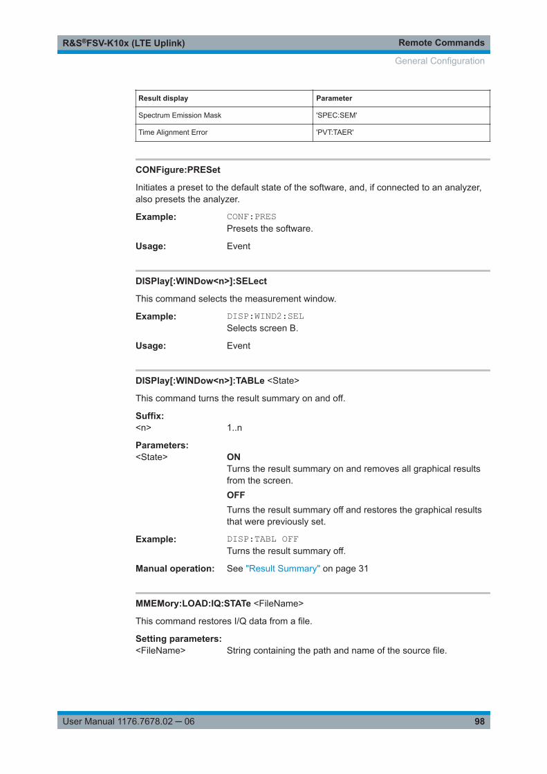
Remote CommandsR&S®FSV-K10x (LTE Uplink)
98User Manual 1176.7678.02 ─ 06
Result display Parameter
Spectrum Emission Mask 'SPEC:SEM'
Time Alignment Error 'PVT:TAER'
CONFigure:PRESet
Initiates a preset to the default state of the software, and, if connected to an analyzer,also presets the analyzer.
Example: CONF:PRESPresets the software.
Usage: Event
DISPlay[:WINDow<n>]:SELect
This command selects the measurement window.
Example: DISP:WIND2:SELSelects screen B.
Usage: Event
DISPlay[:WINDow<n>]:TABLe <State>
This command turns the result summary on and off.
Suffix: <n>
.1..n
Parameters:<State> ON
Turns the result summary on and removes all graphical resultsfrom the screen.OFFTurns the result summary off and restores the graphical resultsthat were previously set.
Example: DISP:TABL OFFTurns the result summary off.
Manual operation: See "Result Summary" on page 31
MMEMory:LOAD:IQ:STATe <FileName>
This command restores I/Q data from a file.
Setting parameters: <FileName> String containing the path and name of the source file.
General Configuration

Remote CommandsR&S®FSV-K10x (LTE Uplink)
99User Manual 1176.7678.02 ─ 06
Example: //Load IQ dataMMEM:LOAD:IQ:STAT 'C:\R_S\Instr\user\data.iqw'
Usage: Setting only
MMEMory:STORe<n>:IQ:STATe <Value>, <FileName>
This command saves I/Q data to a file.
Suffix: <n>
.irrelevant
Parameters:<Value> 1
<FileName> String containing the path and name of the target file.
Example: MMEM:STOR:IQ:STAT 'C:\R_S\Instr\user\data.iq.tar'Saves I/Q data to the specified file.
9.4 Measurement Control
INITiate:CONTinuous........................................................................................................99INITiate[:IMMediate]......................................................................................................... 99INITiate:REFResh.......................................................................................................... 100[SENSe:]SYNC[:CC<cc>][:STATe]?..................................................................................100
INITiate:CONTinuous <State>
This command controls the sweep mode.
Parameters:<State> ON | OFF
ONContinuous sweepOFFSingle sweep*RST: OFF
Example: INIT:CONT OFFSwitches the sequence to single sweep.INIT:CONT ONSwitches the sequence to continuous sweep.
Manual operation: See "Single Sweep and Continuous Sweep" on page 50
INITiate[:IMMediate]
This command initiates a new measurement sequence.
Measurement Control

Remote CommandsR&S®FSV-K10x (LTE Uplink)
100User Manual 1176.7678.02 ─ 06
With a frame count > 0, this means a restart of the corresponding number of measure-ments.
In single sweep mode, you can synchronize to the end of the measurement with *OPC.In continuous sweep mode, synchronization to the end of the sweep is not possible.
Example: INITInitiates a new measurement.
Usage: Event
INITiate:REFResh
This command updates the current I/Q measurement results to reflect the current mea-surement settings.
No new I/Q data is captured. Thus, measurement settings apply to the I/Q data cur-rently in the capture buffer.
The command applies exclusively to I/Q measurements. It requires I/Q data.
Example: INIT:REFRThe application updates the IQ results
Usage: Event
Manual operation: See "Refresh" on page 50
[SENSe:]SYNC[:CC<cc>][:STATe]?
This command queries the current synchronization state.
Suffix: <cc>
.irrelevant
Return values: <State> The string contains the following information:
A zero represents a failure and a one represents a successfulsynchronization.
Example: //Query synchronization stateSYNC:STAT?Would return, e.g. '1' for successful synchronization.
Usage: Query only
9.5 Numeric Result Query
FETCh[:CC<cc>]:CYCPrefix?..........................................................................................101FETCh[:CC<cc>]:PLC:CIDGroup?................................................................................... 102FETCh[:CC<cc>]:PLC:PLID?.......................................................................................... 102FETCh[:CC<cc>]:SUMMary:CRESt[:AVERage]?............................................................... 102FETCh[:CC<cc>]:SUMMary:EVM[:ALL]:MAXimum?.......................................................... 103
Numeric Result Query

Remote CommandsR&S®FSV-K10x (LTE Uplink)
101User Manual 1176.7678.02 ─ 06
FETCh[:CC<cc>]:SUMMary:EVM[:ALL]:MINimum?........................................................... 103FETCh[:CC<cc>]:SUMMary:EVM[:ALL][:AVERage]?......................................................... 103FETCh[:CC<cc>]:SUMMary:EVM:PCHannel:MAXimum?................................................... 103FETCh[:CC<cc>]:SUMMary:EVM:PCHannel:MINimum?.................................................... 103FETCh[:CC<cc>]:SUMMary:EVM:PCHannel[:AVERage]?.................................................. 103FETCh[:CC<cc>]:SUMMary:EVM:PSIGnal:MAXimum?......................................................103FETCh[:CC<cc>]:SUMMary:EVM:PSIGnal:MINimum?.......................................................103FETCh[:CC<cc>]:SUMMary:EVM:PSIGnal[:AVERage]?.....................................................103FETCh[:CC<cc>]:SUMMary:EVM:SDQP[:AVERage]?........................................................104FETCh[:CC<cc>]:SUMMary:EVM:SDSF[:AVERage]?........................................................ 104FETCh[:CC<cc>]:SUMMary:EVM:SDST[:AVERage]?........................................................ 104FETCh[:CC<cc>]:SUMMary:EVM:SDTS[:AVERage]?........................................................ 105FETCh[:CC<cc>]:SUMMary:EVM:UCCD[:AVERage]?........................................................105FETCh[:CC<cc>]:SUMMary:EVM:UCCH[:AVERage]?........................................................105FETCh[:CC<cc>]:SUMMary:EVM:UPRA[:AVERage]?........................................................ 106FETCh[:CC<cc>]:SUMMary:EVM:USQP[:AVERage]?........................................................106FETCh[:CC<cc>]:SUMMary:EVM:USSF[:AVERage]?........................................................ 106FETCh[:CC<cc>]:SUMMary:EVM:USST[:AVERage]?........................................................ 107FETCh[:CC<cc>]:SUMMary:EVM:USTS[:AVERage]?........................................................ 107FETCh[:CC<cc>]:SUMMary:FERRor:MAXimum?.............................................................. 107FETCh[:CC<cc>]:SUMMary:FERRor:MINimum?............................................................... 107FETCh[:CC<cc>]:SUMMary:FERRor[:AVERage]?............................................................. 107FETCh[:CC<cc>]:SUMMary:GIMBalance:MAXimum?........................................................108FETCh[:CC<cc>]:SUMMary:GIMBalance:MINimum?......................................................... 108FETCh[:CC<cc>]:SUMMary:GIMBalance[:AVERage]?....................................................... 108FETCh[:CC<cc>]:SUMMary:IQOFfset:MAXimum?.............................................................108FETCh[:CC<cc>]:SUMMary:IQOFfset:MINimum?..............................................................108FETCh[:CC<cc>]:SUMMary:IQOFfset[:AVERage]?............................................................108FETCh[:CC<cc>]:SUMMary:POWer:MAXimum?............................................................... 109FETCh[:CC<cc>]:SUMMary:POWer:MINimum?................................................................ 109FETCh[:CC<cc>]:SUMMary:POWer[:AVERage]?.............................................................. 109FETCh[:CC<cc>]:SUMMary:QUADerror:MAXimum?..........................................................109FETCh[:CC<cc>]:SUMMary:QUADerror:MINimum?...........................................................109FETCh[:CC<cc>]:SUMMary:QUADerror[:AVERage]?.........................................................109FETCh[:CC<cc>]:SUMMary:SERRor:MAXimum?..............................................................109FETCh[:CC<cc>]:SUMMary:SERRor:MINimum?...............................................................109FETCh[:CC<cc>]:SUMMary:SERRor[:AVERage]?............................................................. 109FETCh[:CC<cc>]:SUMMary:TFRame?............................................................................. 110
FETCh[:CC<cc>]:CYCPrefix?
This command queries the cyclic prefix type that has been detected.
Suffix: <cc>
.irrelevant
Return values: <PrefixType> The command returns -1 if no valid result has been detected yet.
NORMNormal cyclic prefix length detected
Numeric Result Query

Remote CommandsR&S®FSV-K10x (LTE Uplink)
102User Manual 1176.7678.02 ─ 06
EXTExtended cyclic prefix length detected
Example: //Query current cyclic prefix length typeFETC:CYCP?
Usage: Query only
FETCh[:CC<cc>]:PLC:CIDGroup?
This command queries the cell identity group that has been detected.
Suffix: <cc>
.irrelevant
Return values: <CIDGroup> The command returns -1 if no valid result has been detected yet.
Range: 0 to 167
Example: //Query the current cell identity groupFETC:PLC:CIDG?
Usage: Query only
FETCh[:CC<cc>]:PLC:PLID?
This command queries the cell identity that has been detected.
Suffix: <cc>
.irrelevant
Return values: <Identity> The command returns -1 if no valid result has been detected yet.
Range: 0 to 2
Example: //Query the current cell identityFETC:PLC:PLID?
Usage: Query only
FETCh[:CC<cc>]:SUMMary:CRESt[:AVERage]?
This command queries the average crest factor as shown in the result summary.
Suffix: <cc>
.irrelevant
Return values: <CrestFactor> <numeric value>
Crest Factor in dB.
Example: //Query crest factorFETC:SUMM:CRES?
Usage: Query only
Numeric Result Query

Remote CommandsR&S®FSV-K10x (LTE Uplink)
103User Manual 1176.7678.02 ─ 06
Manual operation: See "Result Summary" on page 31
FETCh[:CC<cc>]:SUMMary:EVM[:ALL]:MAXimum?FETCh[:CC<cc>]:SUMMary:EVM[:ALL]:MINimum?FETCh[:CC<cc>]:SUMMary:EVM[:ALL][:AVERage]?This command queries the EVM of all resource elements.
Suffix: <cc>
.irrelevant
Return values: <EVM> <numeric value>
Minimum, maximum or average EVM, depending on the lastcommand syntax element.The unit is % or dB, depending on your selection.
Example: //Query EVMFETC:SUMM:EVM?
Usage: Query only
Manual operation: See "Result Summary" on page 31
FETCh[:CC<cc>]:SUMMary:EVM:PCHannel:MAXimum?FETCh[:CC<cc>]:SUMMary:EVM:PCHannel:MINimum?FETCh[:CC<cc>]:SUMMary:EVM:PCHannel[:AVERage]?This command queries the EVM of all physical channel resource elements.
Suffix: <cc>
.irrelevant
Return values: <EVM> <numeric value>
EVM in % or dB, depending on the unit you have set.
Example: //Query EVMFETC:SUMM:EVM:PCH?
Usage: Query only
Manual operation: See "Result Summary" on page 31
FETCh[:CC<cc>]:SUMMary:EVM:PSIGnal:MAXimum?FETCh[:CC<cc>]:SUMMary:EVM:PSIGnal:MINimum?FETCh[:CC<cc>]:SUMMary:EVM:PSIGnal[:AVERage]?This command queries the EVM of all physical signal resource elements.
Suffix: <cc>
.irrelevant
Numeric Result Query

Remote CommandsR&S®FSV-K10x (LTE Uplink)
104User Manual 1176.7678.02 ─ 06
Return values: <EVM> <numeric value>
Minimum, maximum or average EVM, depending on the lastcommand syntax element.The unit is % or dB, depending on your selection.
Example: //Query EVMFETC:SUMM:EVM:PSIG?
Usage: Query only
Manual operation: See "Result Summary" on page 31
FETCh[:CC<cc>]:SUMMary:EVM:SDQP[:AVERage]?
This command queries the EVM of all DMRS PUSCH resource elements with QPSKmodulation.
Suffix: <cc>
.irrelevant
Return values: <EVM> <numeric value>
EVM in % or dB, depending on the unit you have set.
Example: //Query EVMFETC:SUMM:EVM:SDQP?
Usage: Query only
Manual operation: See "Result Summary" on page 31
FETCh[:CC<cc>]:SUMMary:EVM:SDSF[:AVERage]?
This command queries the EVM of all DMRS PUSCH resource elements with 64QAMmodulation.
Suffix: <cc>
.irrelevant
Return values: <EVM> <numeric value>
EVM in % or dB, depending on the unit you have set.
Example: //Query EVMFETC:SUMM:EVM:SDSF?
Usage: Query only
Manual operation: See "Result Summary" on page 31
FETCh[:CC<cc>]:SUMMary:EVM:SDST[:AVERage]?
This command queries the EVM of all DMRS PUSCH resource elements with 16QAMmodulation.
Numeric Result Query
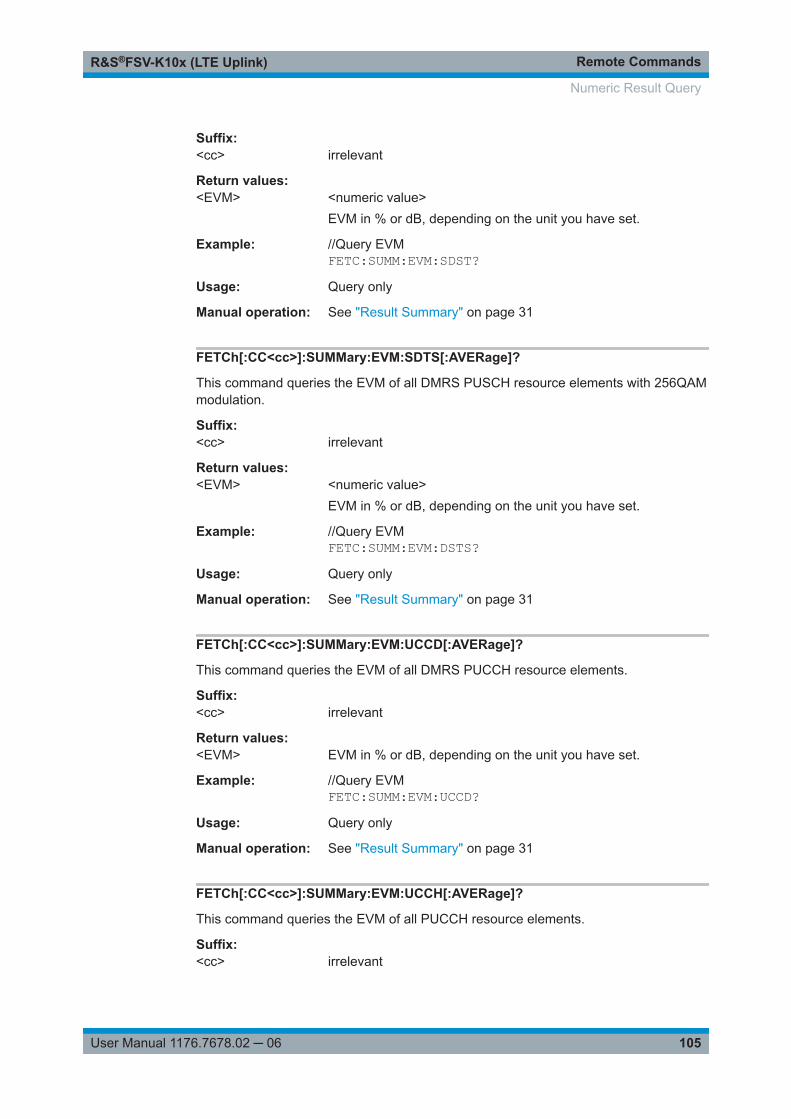
Remote CommandsR&S®FSV-K10x (LTE Uplink)
105User Manual 1176.7678.02 ─ 06
Suffix: <cc>
.irrelevant
Return values: <EVM> <numeric value>
EVM in % or dB, depending on the unit you have set.
Example: //Query EVMFETC:SUMM:EVM:SDST?
Usage: Query only
Manual operation: See "Result Summary" on page 31
FETCh[:CC<cc>]:SUMMary:EVM:SDTS[:AVERage]?
This command queries the EVM of all DMRS PUSCH resource elements with 256QAMmodulation.
Suffix: <cc>
.irrelevant
Return values: <EVM> <numeric value>
EVM in % or dB, depending on the unit you have set.
Example: //Query EVMFETC:SUMM:EVM:DSTS?
Usage: Query only
Manual operation: See "Result Summary" on page 31
FETCh[:CC<cc>]:SUMMary:EVM:UCCD[:AVERage]?
This command queries the EVM of all DMRS PUCCH resource elements.
Suffix: <cc>
.irrelevant
Return values: <EVM> EVM in % or dB, depending on the unit you have set.
Example: //Query EVMFETC:SUMM:EVM:UCCD?
Usage: Query only
Manual operation: See "Result Summary" on page 31
FETCh[:CC<cc>]:SUMMary:EVM:UCCH[:AVERage]?
This command queries the EVM of all PUCCH resource elements.
Suffix: <cc>
.irrelevant
Numeric Result Query

Remote CommandsR&S®FSV-K10x (LTE Uplink)
106User Manual 1176.7678.02 ─ 06
Return values: <EVM> EVM in % or dB, depending on the unit you have set.
Example: //Query EVMFETC:SUMM:EVM:UCCH?
Usage: Query only
Manual operation: See "Result Summary" on page 31
FETCh[:CC<cc>]:SUMMary:EVM:UPRA[:AVERage]?
This command queries the EVM of all PRACH resource elements.
Suffix: <cc>
.irrelevant
Return values: <EVM> EVM in % or dB, depending on the unit you have set.
Example: //Query EVMFETC:SUMM:EVM:UPRA?
Usage: Query only
Manual operation: See "Result Summary" on page 31
FETCh[:CC<cc>]:SUMMary:EVM:USQP[:AVERage]?
This command queries the EVM of all PUSCH resource elements with QPSK modula-tion.
Suffix: <cc>
.irrelevant
Return values: <EVM> <numeric value>
EVM in % or dB, depending on the unit you have set.
Example: //Query EVMFETC:SUMM:EVM:USQP?
Usage: Query only
Manual operation: See "Result Summary" on page 31
FETCh[:CC<cc>]:SUMMary:EVM:USSF[:AVERage]?
This command queries the EVM of all PUSCH resource elements with 64QAM modula-tion.
Suffix: <cc>
.irrelevant
Numeric Result Query

Remote CommandsR&S®FSV-K10x (LTE Uplink)
107User Manual 1176.7678.02 ─ 06
Return values: <EVM> <numeric value>
EVM in % or dB, depending on the unit you have set.
Example: //Query EVMFETC:SUMM:EVM:USSF?
Usage: Query only
Manual operation: See "Result Summary" on page 31
FETCh[:CC<cc>]:SUMMary:EVM:USST[:AVERage]?
This command queries the EVM of all PUSCH resource elements with 16QAM modula-tion.
Suffix: <cc>
.irrelevant
Return values: <EVM> EVM in % or dB, depending on the unit you have set.
Example: //Query EVMFETC:SUMM:EVM:USST?
Usage: Query only
Manual operation: See "Result Summary" on page 31
FETCh[:CC<cc>]:SUMMary:EVM:USTS[:AVERage]?
Suffix: <cc>
.irrelevant
Return values: <EVM> <numeric value>
EVM in % or dB, depending on the unit you have set.
Example: //Query EVMFETC:SUMM:EVM:USTS?
Usage: Query only
Manual operation: See "Result Summary" on page 31
FETCh[:CC<cc>]:SUMMary:FERRor:MAXimum?FETCh[:CC<cc>]:SUMMary:FERRor:MINimum?FETCh[:CC<cc>]:SUMMary:FERRor[:AVERage]?This command queries the frequency error.
Suffix: <cc>
.irrelevant
Numeric Result Query

Remote CommandsR&S®FSV-K10x (LTE Uplink)
108User Manual 1176.7678.02 ─ 06
Return values: <FrequencyError> <numeric value>
Minimum, maximum or average frequency error, depending onthe last command syntax element.Default unit: Hz
Example: //Query average frequency errorFETC:SUMM:FERR?
Usage: Query only
Manual operation: See "Result Summary" on page 31
FETCh[:CC<cc>]:SUMMary:GIMBalance:MAXimum?FETCh[:CC<cc>]:SUMMary:GIMBalance:MINimum?FETCh[:CC<cc>]:SUMMary:GIMBalance[:AVERage]?This command queries the I/Q gain imbalance.
Suffix: <cc>
.irrelevant
Return values: <GainImbalance> <numeric value>
Minimum, maximum or average I/Q imbalance, depending onthe last command syntax element.Default unit: dB
Example: //Query average gain imbalanceFETC:SUMM:GIMB?
Usage: Query only
Manual operation: See "Result Summary" on page 31
FETCh[:CC<cc>]:SUMMary:IQOFfset:MAXimum?FETCh[:CC<cc>]:SUMMary:IQOFfset:MINimum?FETCh[:CC<cc>]:SUMMary:IQOFfset[:AVERage]?This command queries the I/Q offset.
Suffix: <cc>
.irrelevant
Return values: <IQOffset> <numeric value>
Minimum, maximum or average I/Q offset, depending on the lastcommand syntax element.Default unit: dB
Example: //Query average IQ offsetFETC:SUMM:IQOF?
Usage: Query only
Numeric Result Query

Remote CommandsR&S®FSV-K10x (LTE Uplink)
109User Manual 1176.7678.02 ─ 06
Manual operation: See "Result Summary" on page 31
FETCh[:CC<cc>]:SUMMary:POWer:MAXimum?FETCh[:CC<cc>]:SUMMary:POWer:MINimum?FETCh[:CC<cc>]:SUMMary:POWer[:AVERage]?This command queries the total power.
Suffix: <cc>
.irrelevant
Return values: <Power> <numeric value>
Minimum, maximum or average power, depending on the lastcommand syntax element.Default unit: dBm
Example: //Query average total powerFETC:SUMM:POW?
Usage: Query only
Manual operation: See "Result Summary" on page 31
FETCh[:CC<cc>]:SUMMary:QUADerror:MAXimum?FETCh[:CC<cc>]:SUMMary:QUADerror:MINimum?FETCh[:CC<cc>]:SUMMary:QUADerror[:AVERage]?This command queries the quadrature error.
Suffix: <cc>
.irrelevant
Return values: <QuadratureError> <numeric value>
Minimum, maximum or average quadrature error, depending onthe last command syntax element.Default unit: deg
Example: //Query average quadrature errorFETC:SUMM:QUAD?
Usage: Query only
Manual operation: See "Result Summary" on page 31
FETCh[:CC<cc>]:SUMMary:SERRor:MAXimum?FETCh[:CC<cc>]:SUMMary:SERRor:MINimum?FETCh[:CC<cc>]:SUMMary:SERRor[:AVERage]?This command queries the sampling error.
Suffix: <cc>
.irrelevant
Numeric Result Query

Remote CommandsR&S®FSV-K10x (LTE Uplink)
110User Manual 1176.7678.02 ─ 06
Return values: <SamplingError> <numeric value>
Minimum, maximum or average sampling error, depending onthe last command syntax element.Default unit: ppm
Example: //Query average sampling errorFETC:SUMM:SERR?
Usage: Query only
Manual operation: See "Result Summary" on page 31
FETCh[:CC<cc>]:SUMMary:TFRame?
This command queries the (sub)frame start offset as shown in the capture buffer.
Note that you have to select a particular subframe; otherwise the command returns anerror.
Suffix: <cc>
.irrelevant
Return values: <Offset> Time difference between the (sub)frame start and capture buffer
start.Default unit: s
Example: //Query subframe start offsetFETC:SUMM:TFR?
Usage: Query only
Manual operation: See "Capture Buffer" on page 35
9.6 Measurement Result Query
● Using the TRACe[:DATA] Command.....................................................................110● Reading Results....................................................................................................120
9.6.1 Using the TRACe[:DATA] Command
This chapter contains information on the TRACe:DATA command and a detaileddescription of the characteristics of that command.
The TRACe:DATA command queries the trace data or results of the currently activemeasurement or result display. The type, number and structure of the return values arespecific for each result display. In case of results that have any kind of unit, the com-mand returns the results in the unit you have currently set for that result display.
Measurement Result Query

Remote CommandsR&S®FSV-K10x (LTE Uplink)
111User Manual 1176.7678.02 ─ 06
Note also that return values for results that are available for both downlink and uplinkmay be different.
For several result displays, the command also supports various SCPI parameters incombination with the query. If available, each SCPI parameter returns a differentaspect of the results. If SCPI parameters are supported, you have to quote one in thequery.
Example: TRAC2:DATA? TRACE1
The format of the return values is either in ASCII or binary characters and depends onthe format you have set with FORMat[:DATA].
Following this detailed description, you will find a short summary of the most importantfunctions of the command (TRACe[:DATA]?).
Selecting a measurement windowBefore you can query measurement results, you have to select the measurement win-dow that contain the result you would like to query with the command DISPlay[:WINDow<n>]:SELect.
● Adjacent Channel Leakage Ratio.......................................................................... 111● Allocation Summary.............................................................................................. 112● Bit Stream..............................................................................................................113● Capture Buffer....................................................................................................... 114● CCDF.................................................................................................................... 114● Channel and Spectrum Flatness...........................................................................114● Channel and Spectrum Flatness Difference..........................................................115● Channel Flatness SRS..........................................................................................115● Group Delay.......................................................................................................... 115● Constellation Diagram...........................................................................................116● EVM vs Carrier......................................................................................................116● EVM vs Subframe................................................................................................. 117● EVM vs Symbol.....................................................................................................117● Frequency Error vs Symbol...................................................................................117● Inband Emission....................................................................................................118● Power Spectrum....................................................................................................118● Spectrum Emission Mask......................................................................................118● Return Value Codes.............................................................................................. 119
9.6.1.1 Adjacent Channel Leakage Ratio
For the ACLR result display, the number and type of returns values depend on theparameter.
● TRACE1Returns one value for each trace point.
● LIST
Measurement Result Query

Remote CommandsR&S®FSV-K10x (LTE Uplink)
112User Manual 1176.7678.02 ─ 06
Returns the contents of the ACLR table.For each channel, it returns six values.<channel type>, <bandwidth>, <spacing offset>, <power oflower channel>, <power of upper channel>, <limit>, ...The unit of the <bandwidth> and <spacing offset> is Hz.The unit of the power values is either dBm for the TX channel or dB for the neigh-boring channels.The unit of the limit is dB.The <channel type> is encoded. For the code assignment see Chap-ter 9.6.1.18, "Return Value Codes", on page 119.Note that the TX channel does not have a <spacing offset>, <power oflower channel> and <limit>. NaN is returned instead.
9.6.1.2 Allocation Summary
For the allocation summary, the command returns several values for each line of thetable.
● <subframe>● <allocation ID>● <number of RB>● <offset RB>● <modulation>● <absolute power>● <EVM>The data format of the return values is always ASCII.
The return values have the following characteristics.● The <allocation ID is encoded.
For the code assignment, see Chapter 9.6.1.18, "Return Value Codes",on page 119.
● The <modulation> is encoded.For the code assignment, see Chapter 9.6.1.18, "Return Value Codes",on page 119.
● The unit for <absolute power> is always dBm.● The unit for <EVM> depends on UNIT:EVM.
Measurement Result Query

Remote CommandsR&S®FSV-K10x (LTE Uplink)
113User Manual 1176.7678.02 ─ 06
Example:
TRAC:DATA? TRACE1 would return:0, -40, 10, 2, 2, -84.7431947342849, 2.68723483754626E-06,0, -41, 0, 0, 6, -84.7431432845264, 2.37549449584568E-06,0, -42, 0, 0, 6, -80.9404231343884, 3.97834623871343E-06,...
Additional information "ALL"
In addition, there is a line at the end of the allocation summary that shows the averageEVM over all analyzed subframes. This information is also added as the last return val-ues. The "ALL" information has the subframe ID and allocation ID code "-2".
A query result would thus look like this, for example:
//For subframe 0:0, -40, 10, 2, 2, -84.7431947342849, 2.68723483754626E-06,0, -41, 0, 0, 6, -84.7431432845264, 2.37549449584568E-06,(...)//For subframe 1:1, -40, 10, 2, 2, -84.7431947342849, 2.68723483754626E-06,1, -41, 0, 0, 6, -84.7431432845264, 2.37549449584568E-06,(...)//ALL for all subframes-2,-2,,,,,2.13196434228374E-06
9.6.1.3 Bit Stream
For the bit stream result display, the command returns five values and the bitstream foreach line of the table.
<subframe>, <modulation>, <# of symbols/bits>,<hexadecimal/binary numbers>,...All values have no unit. The format of the bit stream depends on Bit Stream Format.
The <modulation> is encoded. For the code assignment see Chapter 9.6.1.18,"Return Value Codes", on page 119.
For symbols or bits that are not transmitted, the command returns● "FF" if the bit stream format is "Symbols"● "9" if the bit stream format is "Bits".
For symbols or bits that could not be decoded because the number of layer exceedsthe number of receive antennas, the command returns● "FE" if the bit stream format is "Symbols"● "8" if the bit stream format is "Bits".
Measurement Result Query

Remote CommandsR&S®FSV-K10x (LTE Uplink)
114User Manual 1176.7678.02 ─ 06
Note that the data format of the return values is always ASCII.
Example:
TRAC:DATA? TRACE1 would return:0, -40, 0, 2, 0, 03, 01, 02, 03, 03, 00, 00, 00, 01, 02, 02, ...<continues like this until the next data block starts or the end of data is reached>0, -40, 0, 2, 32, 03, 03, 00, 00, 03, 01, 02, 00, 01, 00, ...
9.6.1.4 Capture Buffer
For the capture buffer result display, the command returns one value for each I/Q sam-ple in the capture buffer.
<absolute power>, ...The unit is always dBm.
The following parameters are supported.● TRACE1
9.6.1.5 CCDF
For the CCDF result display, the type of return values depends on the parameter.
● TRACE1Returns the probability values (y-axis).<# of values>, <probability>, ...The unit is always %.The first value that is returned is the number of the following values.
● TRACE2Returns the corresponding power levels (x-axis).<# of values>, <relative power>, ...The unit is always dB.The first value that is returned is the number of the following values.
9.6.1.6 Channel and Spectrum Flatness
For the channel flatness result display, the command returns one value for each tracepoint.
<relative power>, ...The unit is always dB.
The following parameters are supported.● TRACE1
Returns the average power over all subframes.
Measurement Result Query

Remote CommandsR&S®FSV-K10x (LTE Uplink)
115User Manual 1176.7678.02 ─ 06
● TRACE2Returns the minimum power found over all subframes. If you are analyzing a partic-ular subframe, it returns nothing.
● TRACE3Returns the maximum power found over all subframes. If you are analyzing a par-ticular subframe, it returns nothing.
9.6.1.7 Channel and Spectrum Flatness Difference
For the channel flatness difference result display, the command returns one value foreach trace point.
<relative power>, ...The unit is always dB. The number of values depends on the selected LTE bandwidth.
The following parameters are supported.● TRACE1
Returns the average power over all subframes.● TRACE2
Returns the minimum power found over all subframes. If you are analyzing a partic-ular subframe, it returns nothing.
● TRACE3Returns the maximum power found over all subframes. If you are analyzing a par-ticular subframe, it returns nothing.
9.6.1.8 Channel Flatness SRS
For the channel flatness SRS result display, the command returns one value for eachtrace point.
<relative power>, ...The unit is always dB.
The following parameters are supported.● TRACE1
Returns the average power over all subframes.● TRACE2
Returns the minimum power found over all subframes. If you are analyzing a partic-ular subframe, it returns nothing.
● TRACE3Returns the maximum power found over all subframes. If you are analyzing a par-ticular subframe, it returns nothing.
9.6.1.9 Group Delay
For the group delay result display, the command returns one value for each trace point.
<group delay>, ...
Measurement Result Query

Remote CommandsR&S®FSV-K10x (LTE Uplink)
116User Manual 1176.7678.02 ─ 06
The unit is always ns. The number of values depends on the selected LTE bandwidth.
The following parameters are supported.● TRACE1
Returns the average group delay over all subframes.● TRACE2
Returns the minimum group delay found over all subframes. If you are analyzing aparticular subframe, it returns nothing.
● TRACE3Returns the maximum group delay found over all subframes. If you are analyzing aparticular subframe, it returns nothing.
9.6.1.10 Constellation Diagram
For the constellation diagram, the command returns two values for each constellationpoint.
<I[SF0][Sym0][Carrier1]>, <Q[SF0][Sym0][Carrier1]>, ..., <I[SF0][Sym0][Carrier(n)]>, <Q[SF0][Sym0][Car-rier(n)]>,
<I[SF0][Sym1][Carrier1]>, <Q[SF0][Sym1][Carrier1]>, ..., <I[SF0][Sym1][Carrier(n)]>, <Q[SF0][Sym1][Car-rier(n)]>,
<I[SF0][Sym(n)][Carrier1]>, <Q[SF0][Sym(n)][Carrier1]>, ..., <I[SF0][Sym(n)][Carrier(n)]>, <Q[SF0][Sym(n)][Carrier(n)]>,
<I[SF1][Sym0][Carrier1]>, <Q[SF1][Sym0][Carrier1]>, ..., <I[SF1][Sym0][Carrier(n)]>, <Q[SF1][Sym0][Car-rier(n)]>,
<I[SF1][Sym1][Carrier1]>, <Q[SF1][Sym1][Carrier1]>, ..., <I[SF1][Sym1][Carrier(n)]>, <Q[SF1][Sym1][Car-rier(n)]>,
<I[SF(n)][Sym(n)][Carrier1]>, <Q[SF(n)][Sym(n)][Carrier1]>, ..., <I[SF(n)][Sym(n)][Carrier(n)]>, <Q[SF(n)][Sym(n)][Carrier(n)]>
With SF = subframe and Sym = symbol of that subframe.
The I and Q values have no unit.
The number of return values depends on the constellation selection. By default, itreturns all resource elements including the DC carrier.
The following parameters are supported.● TRACE1
Returns all constellation points included in the selection.● TRACE2
Returns the constellation points of the reference symbols included in the selection.● TRACE3
Returns the constellation points of the SRS included in the selection.
9.6.1.11 EVM vs Carrier
For the EVM vs carrier result display, the command returns one value for each subcar-rier that has been analyzed.
<EVM>, ...
Measurement Result Query

Remote CommandsR&S®FSV-K10x (LTE Uplink)
117User Manual 1176.7678.02 ─ 06
The unit depends on UNIT:EVM.
The following parameters are supported.● TRACE1
Returns the average EVM over all subframes● TRACE2
Returns the minimum EVM found over all subframes. If you are analyzing a particu-lar subframe, it returns nothing.
● TRACE3Returns the maximum EVM found over all subframes. If you are analyzing a partic-ular subframe, it returns nothing.
9.6.1.12 EVM vs Subframe
For the EVM vs subframe result display, the command returns one value for each sub-frame that has been analyzed.
<EVM>, ...The unit depends on UNIT:EVM.
The following parameters are supported.● TRACE1
9.6.1.13 EVM vs Symbol
For the EVM vs symbol result display, the command returns one value for each OFDMsymbol that has been analyzed.
<EVM>, ...For measurements on a single subframe, the command returns the symbols of thatsubframe only.
The unit depends on UNIT:EVM.
The following parameters are supported.● TRACE1
9.6.1.14 Frequency Error vs Symbol
For the frequency error vs symbol result display, the command returns one value foreach OFDM symbol that has been analyzed.
<frequency error>,...The unit is always Hz.
The following parameters are supported.● TRACE1
Measurement Result Query

Remote CommandsR&S®FSV-K10x (LTE Uplink)
118User Manual 1176.7678.02 ─ 06
9.6.1.15 Inband Emission
For the inband emission result display, the number and type of returns values dependon the parameter.
● TRACE1Returns the relative resource block indices (x-axis values).<RB index>, ...The resource block index has no unit.
● TRACE2Returns one value for each resource block index.<relative power>, ...The unit of the relative inband emission is dB.
● TRACE3Returns the data points of the upper limit line.<limit>, ...The unit is always dB.
Note that you have to select a particular subframe to get results.
9.6.1.16 Power Spectrum
For the power spectrum result display, the command returns one value for each tracepoint.
<power>,...The unit is always dBm/Hz.
The following parameters are supported.● TRACE1
9.6.1.17 Spectrum Emission Mask
For the SEM measurement, the number and type of returns values depend on theparameter.
● TRACE1Returns one value for each trace point.<absolute power>, ...The unit is always dBm.
● LISTReturns the contents of the SEM table. For every frequency in the spectrum emis-sion mask, it returns 11 values.<index>, <start frequency in Hz>, <stop frequency in Hz>,<RBW in Hz>, <limit fail frequency in Hz>, <absolute power indBm>, <relative power in dBc>, <limit distance in dB>, <limitcheck result>, <reserved>, <reserved>...The <limit check result> is either a 0 (for PASS) or a 1 (for FAIL).
Measurement Result Query

Remote CommandsR&S®FSV-K10x (LTE Uplink)
119User Manual 1176.7678.02 ─ 06
9.6.1.18 Return Value Codes
<number of symbols or bits>
In hexadecimal mode, this represents the number of symbols to be transmitted. Inbinary mode, it represents the number of bits to be transmitted.
<allocation ID>
Represents the allocation ID. The value is a number in the range {1...-70}.● 1 = Reference symbol● 0 = Data symbol● -1 = Invalid● -40 = PUSCH● -41 = DMRS PUSCH● -42 = SRS PUSCH● -50 = PUCCH● -51 = DMRS PUCCH● -70 = PRACH
<channel type>
● 0 = TX channel● 1 = adjacent channel● 2 = alternate channel
<modulation>
Represents the modulation scheme.● 0 = unrecognized● 1 = RBPSK● 2 = QPSK● 3 = 16QAM● 4 = 64QAM● 5 = 8PSK● 6 = CAZAC● 7 = mixed modulation● 8 = BPSK● 14 = 256QAM
FORMat[:DATA]............................................................................................................. 120TRACe[:DATA]?.............................................................................................................120
Measurement Result Query

Remote CommandsR&S®FSV-K10x (LTE Uplink)
120User Manual 1176.7678.02 ─ 06
FORMat[:DATA] <Format>
This command selects the data format for the data transmission between theR&S FSVA/FSV and the remote client.
Parameters:<Format> ASCii | REAL
*RST: ASCii
Example: //Select data formatFORM REAL
TRACe[:DATA]? <Result>
This command returns the trace data for the current measurement or result display.
For more information see Chapter 9.6.1, "Using the TRACe[:DATA] Command",on page 110.
Query parameters: TRACE1 | TRACE2 |TRACE3
LIST
Usage: Query only
9.6.2 Reading Results
CALCulate<n>:LIMit<li>:ACPower:ACHannel:RESult?.......................................................120CALCulate<n>:LIMit<li>:ACPower:ALTernate<alt>:RESult?................................................121CALCulate<n>:MARKer<m>:FUNCtion:POWer<sb>:RESult[:CURRent]?............................ 122
CALCulate<n>:LIMit<li>:ACPower:ACHannel:RESult? [<Result>]
This command queries the limit check results for the adjacent channels during ACLRmeasurements.
Suffix: <n>
.irrelevant
<li> irrelevant
Query parameters: <Result> ALL
Queries the overall limit check results.RELQueries the channel power limit check results.
Measurement Result Query

Remote CommandsR&S®FSV-K10x (LTE Uplink)
121User Manual 1176.7678.02 ─ 06
ABSQueries the distance to the limit line.
Return values: <LimitCheck> Returns two values, one for the upper and one for the lower
adjacent channel.PASSEDLimit check has passed.FAILEDLimit check has failed.
Example: //Query results of the adjacent channel limit checkCALC:LIM:ACP:ACH:RES?
Example: //Query results of the adjacent channel limit checkCALC:LIM:ACP:ACH:RES? ABS
Usage: Query only
CALCulate<n>:LIMit<li>:ACPower:ALTernate<alt>:RESult? [<Result>]
This command queries the limit check results for the alternate channels during ACLRmeasurements.
Suffix: <n>
.irrelevant
<li> irrelevant
<alt> irrelevant
Query parameters: <Result> ALL
Queries the overall limit check results.RELQueries the channel power limit check results.ABSQueries the distance to the limit line.
Return values: <LimitCheck> Returns two values, one for the upper and one for the lower
alternate channel.PASSEDLimit check has passed.FAILEDLimit check has failed.
Example: //Query results of the alternate channel limit checkCALC:LIM:ACP:ALT:RES?
Example: //Query results of the alternate channel limit checkCALC:LIM:ACP:ACH:RES? ABS
Usage: Query only
Measurement Result Query
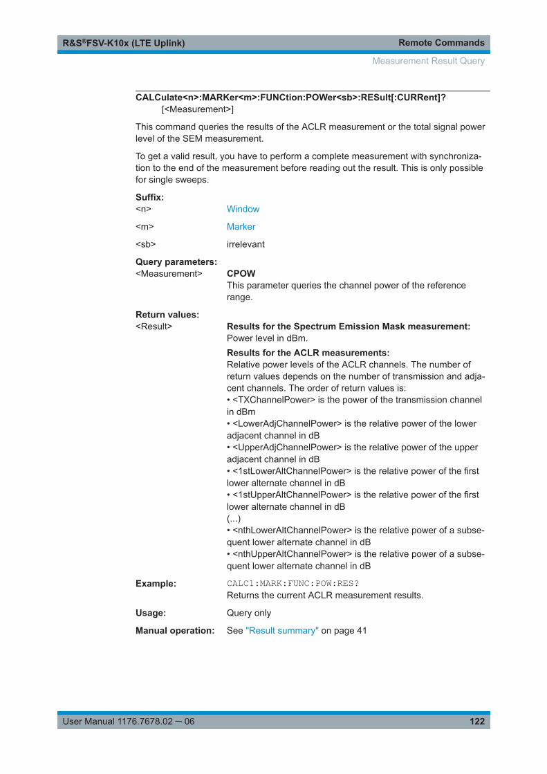
Remote CommandsR&S®FSV-K10x (LTE Uplink)
122User Manual 1176.7678.02 ─ 06
CALCulate<n>:MARKer<m>:FUNCtion:POWer<sb>:RESult[:CURRent]?[<Measurement>]
This command queries the results of the ACLR measurement or the total signal powerlevel of the SEM measurement.
To get a valid result, you have to perform a complete measurement with synchroniza-tion to the end of the measurement before reading out the result. This is only possiblefor single sweeps.
Suffix: <n>
.Window
<m> Marker
<sb> irrelevant
Query parameters: <Measurement> CPOW
This parameter queries the channel power of the referencerange.
Return values: <Result> Results for the Spectrum Emission Mask measurement:
Power level in dBm.Results for the ACLR measurements:Relative power levels of the ACLR channels. The number ofreturn values depends on the number of transmission and adja-cent channels. The order of return values is:• <TXChannelPower> is the power of the transmission channelin dBm• <LowerAdjChannelPower> is the relative power of the loweradjacent channel in dB• <UpperAdjChannelPower> is the relative power of the upperadjacent channel in dB• <1stLowerAltChannelPower> is the relative power of the firstlower alternate channel in dB• <1stUpperAltChannelPower> is the relative power of the firstlower alternate channel in dB(...)• <nthLowerAltChannelPower> is the relative power of a subse-quent lower alternate channel in dB• <nthUpperAltChannelPower> is the relative power of a subse-quent lower alternate channel in dB
Example: CALC1:MARK:FUNC:POW:RES?Returns the current ACLR measurement results.
Usage: Query only
Manual operation: See "Result summary" on page 41
Measurement Result Query

Remote CommandsR&S®FSV-K10x (LTE Uplink)
123User Manual 1176.7678.02 ─ 06
9.7 General Settings
● Defining Signal Characteristics............................................................................. 123● Configuring the Input Level................................................................................... 125● Configuring the Data Capture............................................................................... 128
9.7.1 Defining Signal Characteristics
Commands to configure signal characteristics described elsewhere.● FETCh[:CC<cc>]:CYCPrefix?CONFigure[:LTE]:DUPLexing.......................................................................................... 123CONFigure[:LTE]:LDIRection...........................................................................................123CONFigure[:LTE]:UL[:CC<cc>]:BW..................................................................................123CONFigure[:LTE]:UL[:CC<cc>]:CYCPrefix........................................................................ 124[SENSe:]FREQuency:CENTer[:CC<cc>]...........................................................................124
CONFigure[:LTE]:DUPLexing <Duplexing>
This command selects the duplexing mode.
Parameters:<Duplexing> TDD
Time division duplexFDDFrequency division duplex*RST: FDD
Example: //Select time division duplexCONF:DUPL TDD
Manual operation: See "Selecting the LTE mode" on page 51
CONFigure[:LTE]:LDIRection <Direction>
This command selects the link direction.
Parameters:<Direction> DL
Selects the mode to analyze downlink signals.ULSelects the mode to analyze uplink signals.
Example: //Select downlink modeCONF:LDIR DL
Manual operation: See "Selecting the LTE mode" on page 51
CONFigure[:LTE]:UL[:CC<cc>]:BW <Bandwidth>
This command selects the channel bandwidth.
General Settings
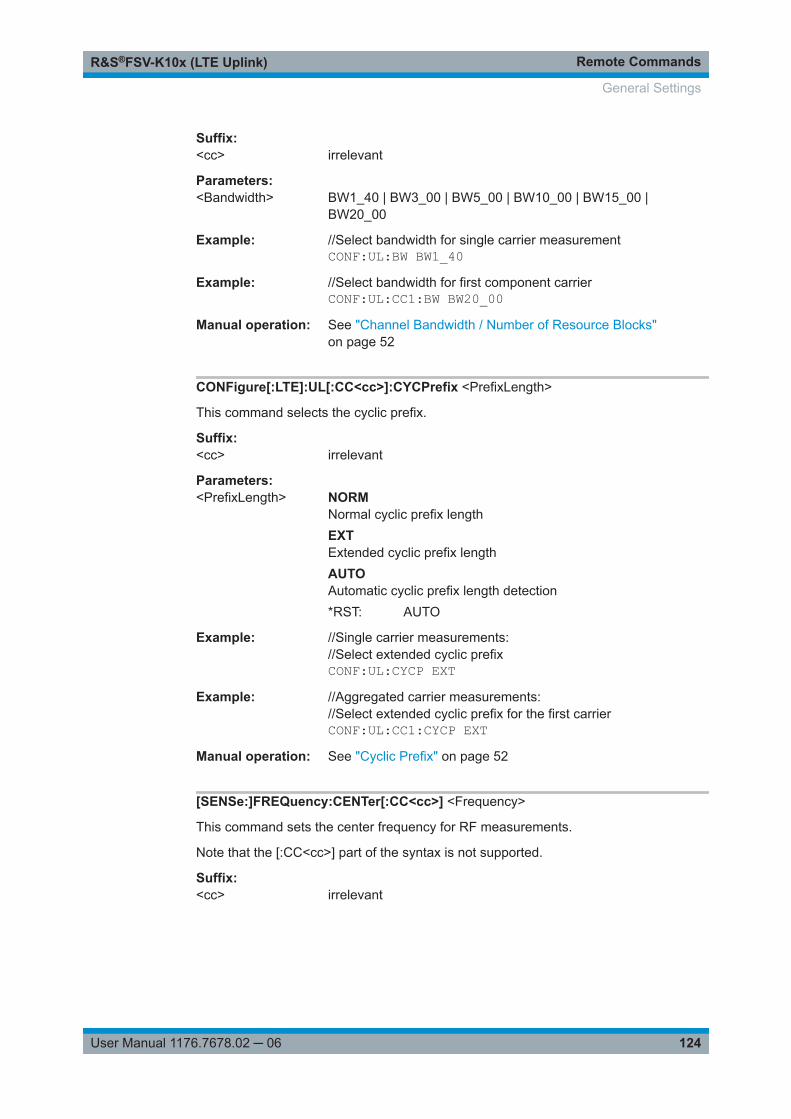
Remote CommandsR&S®FSV-K10x (LTE Uplink)
124User Manual 1176.7678.02 ─ 06
Suffix: <cc>
.irrelevant
Parameters:<Bandwidth> BW1_40 | BW3_00 | BW5_00 | BW10_00 | BW15_00 |
BW20_00
Example: //Select bandwidth for single carrier measurementCONF:UL:BW BW1_40
Example: //Select bandwidth for first component carrierCONF:UL:CC1:BW BW20_00
Manual operation: See "Channel Bandwidth / Number of Resource Blocks"on page 52
CONFigure[:LTE]:UL[:CC<cc>]:CYCPrefix <PrefixLength>
This command selects the cyclic prefix.
Suffix: <cc>
.irrelevant
Parameters:<PrefixLength> NORM
Normal cyclic prefix lengthEXTExtended cyclic prefix lengthAUTOAutomatic cyclic prefix length detection*RST: AUTO
Example: //Single carrier measurements://Select extended cyclic prefixCONF:UL:CYCP EXT
Example: //Aggregated carrier measurements://Select extended cyclic prefix for the first carrierCONF:UL:CC1:CYCP EXT
Manual operation: See "Cyclic Prefix" on page 52
[SENSe:]FREQuency:CENTer[:CC<cc>] <Frequency>
This command sets the center frequency for RF measurements.
Note that the [:CC<cc>] part of the syntax is not supported.
Suffix: <cc>
.irrelevant
General Settings

Remote CommandsR&S®FSV-K10x (LTE Uplink)
125User Manual 1176.7678.02 ─ 06
Parameters:<Frequency> <numeric value>
Range: fmin to fmax*RST: 1 GHzDefault unit: Hz
Example: //Define frequency for measurement on one carrier:FREQ:CENT 1GHZ
Manual operation: See "Center Frequency" on page 51
9.7.2 Configuring the Input Level
DISPlay[:WINDow<n>]:TRACe<t>:Y[:SCALe]:RLEVel........................................................125DISPlay[:WINDow<n>]:TRACe<t>:Y[:SCALe]:RLEVel:OFFSet........................................... 125INPut<ip>:ATTenuation<ant>...........................................................................................126INPut<ip>:EATT<ant>.....................................................................................................126INPut<ip>:EATT<ant>:STATe.......................................................................................... 126INPut<ip>:EATT<ant>:AUTO...........................................................................................127[SENSe:]POWer:AUTO[:STATe].......................................................................................127[SENSe:]POWer:AUTO:TIME..........................................................................................128
DISPlay[:WINDow<n>]:TRACe<t>:Y[:SCALe]:RLEVel <ReferenceLevel>
This command defines the reference level (for all traces in all windows).
With a reference level offset ≠ 0, the value range of the reference level is modified bythe offset.
Suffix: <n>
.irrelevant
<t> irrelevant
Parameters:<ReferenceLevel> The unit is variable.
Range: see datasheet*RST: 0 dBmDefault unit: DBM
Example: DISP:TRAC:Y:RLEV -60dBmManual operation: See "Reference Level" on page 53
DISPlay[:WINDow<n>]:TRACe<t>:Y[:SCALe]:RLEVel:OFFSet <Attenuation>
This command selects the external attenuation or gain applied to the RF signal.
Parameters:<Attenuation> <numeric value>
*RST: 0Default unit: dB
General Settings

Remote CommandsR&S®FSV-K10x (LTE Uplink)
126User Manual 1176.7678.02 ─ 06
Example: DISP:TRAC:Y:RLEV:OFFS 10Sets an external attenuation of 10 dB.
Manual operation: See "External Attenuation" on page 53
INPut<ip>:ATTenuation<ant> <Attenuation>
This command defines the RF attenuation level.
Suffix: <ip>
.irrelevant
<ant> irrelevant
Parameters:<Attenuation> *RST: 10 dB
Default unit: dB
Example: //Define RF attenuationINP:ATT:AUTO OFFINP:ATT 10
Manual operation: See "RF Attenuation" on page 54
INPut<ip>:EATT<ant> <Attenuation>
This command defines the electronic attenuation level.
If the current reference level is not compatible with an attenuation that has been setmanually, the command also adjusts the reference level.
This command is available with the optional Electronic Attenuator, but not if you areusing the optional Digital Baseband Input.
Suffix: <ip>
.irrelevant
<ant> Connected instrument
Parameters:<Attenuation> Attenuation level in dB.
Default unit: dB
Example: //Define signal attenuationINP:EATT 10
INPut<ip>:EATT<ant>:STATe <State>
This command turns the electronic attenuator on and off.
This command is available with the optional Electronic Attenuator, but not if you areusing the optional Digital Baseband Input.
Suffix: <ip>
.irrelevant
General Settings

Remote CommandsR&S®FSV-K10x (LTE Uplink)
127User Manual 1176.7678.02 ─ 06
<ant> 1...4Connected instrument
Parameters:<State> ON | OFF
*RST: OFF
Example: //Turn on electronic attenuationINP:EATT:STAT ON
INPut<ip>:EATT<ant>:AUTO <State>
This command turns automatic selection of the electronic attenuation on and off.
If on, electronic attenuation reduces the mechanical attenuation whenever possible.
This command is available with the optional Electronic Attenuator, but not if you areusing the optional Digital Baseband Input.
Suffix: <ip>
.irrelevant
<ant> 1...4Connected instrument
Parameters:<State> ON | OFF | 1 | 0
*RST: OFF
Example: //Turn on automatic selection of electronic attenuationINP:EATT:AUTO ON
[SENSe:]POWer:AUTO[:STATe] <State>
This command initiates a measurement that determines the ideal reference level.
Parameters:<State> OFF
Performs no automatic reference level detection.ONPerforms an automatic reference level detection before eachmeasurement.ONCEPerforms an automatic reference level once.*RST: ON
Example: POW:AUTO2 ONActivate auto level for analyzer number 2.
Manual operation: See "Auto Level" on page 50See "Auto Level" on page 53
General Settings

Remote CommandsR&S®FSV-K10x (LTE Uplink)
128User Manual 1176.7678.02 ─ 06
[SENSe:]POWer:AUTO:TIME <Time>
This command defines the track time for the auto level process.
Parameters:<Time> <numeric value>
*RST: 100 msDefault unit: s
Example: POW:AUTO:TIME 200msAn auto level track time of 200 ms gets set.
Manual operation: See "Auto Level" on page 53
9.7.3 Configuring the Data Capture
[SENSe:][LTE:]FRAMe:COUNt........................................................................................ 128[SENSe:][LTE:]FRAMe:COUNt:AUTO.............................................................................. 128[SENSe:][LTE:]FRAMe:COUNt:STATe.............................................................................. 129[SENSe:]SWEep:TIME................................................................................................... 129
[SENSe:][LTE:]FRAMe:COUNt <Subframes>
This command defines the number of frames you want to analyze.
Prerequisites for this command● Turn on overall frame count ([SENSe:][LTE:]FRAMe:COUNt:STATe).● Turn on manual selection of frames to analyze ([SENSe:][LTE:]FRAMe:COUNt:
AUTO).
Parameters:<Subframes> <numeric value> (integer only)
*RST: 1
Example: //Define number of frames to analyze manuallyFRAM:COUN:STAT ONFRAM:COUN:AUTO OFFFRAM:COUN 20
Manual operation: See "Number of Frames to Analyze" on page 55
[SENSe:][LTE:]FRAMe:COUNt:AUTO <State>
This command turns automatic selection of the number of frames to analyze on andoff.
Parameters:<State> ON | 1
Selects the analyzed number of frames according to the LTEstandard.OFF | 0Turns on manual selection of the number of frames.
General Settings

Remote CommandsR&S®FSV-K10x (LTE Uplink)
129User Manual 1176.7678.02 ─ 06
Example: //Turn on automatic selection of analyzed framesFRAM:COUN:AUTO ON
Manual operation: See "Auto According to Standard" on page 55
[SENSe:][LTE:]FRAMe:COUNt:STATe <State>
This command turns manual selection of the number of frames you want to analyze onand off.
Parameters:<State> ON | 1
You can set the number of frames to analyze.OFF | 0The R&S FSVA/FSV analyzes the frames captured in a singlesweep.*RST: ON
Example: //Turn on manual selection of number of framesFRAM:COUN:STAT ON
Manual operation: See "Overall Frame Count" on page 54
[SENSe:]SWEep:TIME <CaptureLength>
This command defines the capture time.
When you are performing an ACLR measurement, the command defines the sweeptime. (Note that you have to select the ACLR measurement first, before defining asweep time - otherwise, the command defines the capture time for I/Q measurements.)
Parameters:<CaptureLength> <numeric value>
*RST: 20.1 ms / 40.1 ms (DL TDD)Default unit: s
Example: //Define capture timeSWE:TIME 40ms
Manual operation: See "Capture Time" on page 54See "Sweep Time" on page 60
9.8 Advanced Settings
● Controlling I/Q Data...............................................................................................130● Controlling the Input..............................................................................................130● Configuring the Digital I/Q Input............................................................................131
Advanced Settings

Remote CommandsR&S®FSV-K10x (LTE Uplink)
130User Manual 1176.7678.02 ─ 06
9.8.1 Controlling I/Q Data
[SENSe:]SWAPiq...........................................................................................................130
[SENSe:]SWAPiq <State>
This command turns a swap of the I and Q branches on and off.
Parameters:<State> ON | OFF | 1 | 0
*RST: OFF
Example: //Swap I and Q branchesSWAP ON
Manual operation: See "Swap I/Q" on page 60
9.8.2 Controlling the Input
For information on the remote commands for reference level and attenuation settingssee Chapter 9.7.2, "Configuring the Input Level", on page 125.
INPut<ip>:SELect...........................................................................................................130INPut<n>:FILTer:YIG:AUTO............................................................................................ 130INPut<ip>:FILTer:YIG[:STATe]..........................................................................................131TRACe<n>:IQ:FILTer:FLATness...................................................................................... 131
INPut<ip>:SELect <Source>
This command selects the signal source.
Suffix: <ip>
.1..n
Parameters:<Source> RF
Selects the RF input as the signal source.AIQSelects the analog baseband input as the data source. Thissource is available only with option R&S FSVA/FSV-B71.DIQSelects the digital baseband input as the data source. Thissource is available only with option R&S FSVA/FSV-B17.
Example: INP DIQSelects the digital baseband input.
Manual operation: See "Selecting the Input Source" on page 61
INPut<n>:FILTer:YIG:AUTO <State>
This command turns automatic control of the YIG filter on and off.
Advanced Settings

Remote CommandsR&S®FSV-K10x (LTE Uplink)
131User Manual 1176.7678.02 ─ 06
Parameters:<State> ON | OFF
*RST: ON
Example: INP:FILT:YIG:AUTO ONActivates automatic control of the YIG filter.
Manual operation: See "Yig Filter" on page 61
INPut<ip>:FILTer:YIG[:STATe] <State>
This command removes or adds the YIG filter from the signal path.
If you remove the filter, you can use the maximum bandwidth, but image frequencyrejection is no longer ensured.
Suffix: <ip>
.1..n
Parameters:<State> ON | OFF
*RST: ON
Example: INP:FILT:YIG OFFRemoves the YIG filter from the signal path.
Manual operation: See "Yig Filter" on page 61
TRACe<n>:IQ:FILTer:FLATness <arg0>
This command turns the wideband filter on and off.
Suffix: <n>
.1..n
Parameters:<arg0> NORMal | WIDE
NORMalUses the normal filter.WIDETurns the wideband filter on.*RST: NORMal
Example: TRAC:IQ:FILT:FLAT WIDETurns the wideband filter on.
9.8.3 Configuring the Digital I/Q Input
INPut<ip>:DIQ:SRATe.................................................................................................... 132INPut<ip>:DIQ:RANGe[:UPPer].......................................................................................132
Advanced Settings

Remote CommandsR&S®FSV-K10x (LTE Uplink)
132User Manual 1176.7678.02 ─ 06
INPut<ip>:DIQ:SRATe <SampleRate>
This command defines the sampling rate for a digital I/Q signal source.
Suffix: <ip>
.1..n
Parameters:<SampleRate> *RST: 10 MHz
Default unit: Hz
Example: INP:DIQ:SRAT 10MHZDefines a sampling rate of 10 MHz.
Manual operation: See "Sampling Rate (Input Data Rate)" on page 62
INPut<ip>:DIQ:RANGe[:UPPer] <Level>
This command defines the full scale level for a digital I/Q signal source.
Suffix: <ip>
.1..n
Parameters:<Level> *RST: 1 V
Example: INP:DIQ:RANG 0.7Sets the full scale level to 0.7 V.
Manual operation: See "Full Scale Level" on page 62
9.9 Trigger Configuration
The trigger functionality of the LTE measurement application is the same as that of theR&S FSVA/FSV.
For a comprehensive description of the available remote control commands for triggerconfiguration, see the documentation of the R&S FSVA/FSV.
TRIGger[:SEQuence]:HOLDoff<ant>[:TIME]..................................................................... 132TRIGger[:SEQuence]:IFPower:HOLDoff........................................................................... 133TRIGger[:SEQuence]:IFPower:HYSTeresis.......................................................................133TRIGger[:SEQuence]:LEVel<ant>[:EXTernal<tp>]............................................................. 133TRIGger[:SEQuence]:LEVel<ant>:POWer........................................................................ 134TRIGger[:SEQuence]:LEVel<ant>:RFPower..................................................................... 134TRIGger[:SEQuence]:MODE<ant>...................................................................................134
TRIGger[:SEQuence]:HOLDoff<ant>[:TIME] <Offset>
This command defines the trigger offset.
Suffix: <ant>
.irrelevant
Trigger Configuration

Remote CommandsR&S®FSV-K10x (LTE Uplink)
133User Manual 1176.7678.02 ─ 06
Parameters:<Offset> <numeric value>
*RST: 0 sDefault unit: s
Example: //Define trigger offsetTRIG:HOLD 5MS
Manual operation: See "Trigger Characteristics" on page 56
TRIGger[:SEQuence]:IFPower:HOLDoff <Period>
This command defines the holding time before the next trigger event.
Note that this command is available for any trigger source, not just IF Power.
Parameters:<Period> Range: 150 ns to 10 s
*RST: 150 nsDefault unit: s
Example: TRIG:IFP:HOLD 1Defines a holdoff of 1 second.
Manual operation: See "Trigger Characteristics" on page 56
TRIGger[:SEQuence]:IFPower:HYSTeresis <Hysteresis>
This command defines the trigger hysteresis.
Parameters:<Hysteresis> Range: 3 to 50
*RST: 3Default unit: dB
Example: TRIG:IFP:HYST 10Defines a trigger hysteresis of 10 dB.
Manual operation: See "Trigger Characteristics" on page 56
TRIGger[:SEQuence]:LEVel<ant>[:EXTernal<tp>] <Level>
This command defines the level for an external trigger.
Suffix: <ant>
.irrelevant
<tp> irrelevant
Parameters:<Level> Range: 0.5 V to 3.5 V
*RST: 1.4 VDefault unit: V
Trigger Configuration

Remote CommandsR&S®FSV-K10x (LTE Uplink)
134User Manual 1176.7678.02 ─ 06
Example: //Define trigger levelTRIG:LEV 2V
Manual operation: See "Trigger Characteristics" on page 56
TRIGger[:SEQuence]:LEVel<ant>:POWer <Level>
This command defines the trigger level for an IF power trigger.
Suffix: <ant>
.1..nirrelevant
Parameters:<Level> Default unit: DBM
Example: TRIG:LEV:POW 10Defines a trigger level of 10 dBm.
Manual operation: See "Trigger Characteristics" on page 56
TRIGger[:SEQuence]:LEVel<ant>:RFPower <Level>
This command defines the power level the RF input must exceed to cause a triggerevent. Note that any RF attenuation or preamplification is considered when the triggerlevel is analyzed. If defined, a reference level offset is also considered.
The input signal must be between 500 MHz and 8 GHz.
Suffix: <ant>
.irrelevant
Parameters:<Level> <numeric value>
For details on available trigger levels and trigger bandwidths seethe data sheet.*RST: -20 dBmDefault unit: dBm
Example: //Define trigger levelTRIG:SOUR RFPTRIG:LEV:RFP -30dBm
Manual operation: See "Trigger Characteristics" on page 56
TRIGger[:SEQuence]:MODE<ant> <Source>
This command selects the trigger source.
Trigger Configuration

Remote CommandsR&S®FSV-K10x (LTE Uplink)
135User Manual 1176.7678.02 ─ 06
Suffix: <ant>
.1..n
Parameters:<Source> EXTernal
Selects external trigger source.IFPowerSelects the IF power trigger source.IMMediateSelects free run trigger source.PSENSelects power sensor trigger source.RFPowerSelects RF power trigger source.*RST: IMMediate
Example: //Select an external trigger sourceTRIG:MODE EXT
Manual operation: See "Trigger Source" on page 56
9.10 Spectrum Measurements
MMEMory:LOAD:SEMsettings.........................................................................................135[SENSe]:FREQuency:SPAN............................................................................................136[SENSe]:FREQuency:SPAN:AUTO..................................................................................136[SENSe:]POWer:ACHannel:AACHannel...........................................................................136[SENSe]:POWer:ACHannel:BANDwidth:CHANnel2........................................................... 137[SENSe]:POWer:ACHannel:SPACing:CHANnel................................................................ 137[SENSe]:POWer:ACHannel:TXCHannels:COUNt.............................................................. 137[SENSe:]POWer:NCORrection........................................................................................ 138[SENSe:]POWer:SEM:UL:REQuirement...........................................................................138[SENSe:]POWer:SEM:USERfile...................................................................................... 138[SENSe:]SWEep:EGATe:AUTO....................................................................................... 139
MMEMory:LOAD:SEMsettings <FileName>
This command loads a custom SEM file.
The R&S FSVA/FSV only evaluates the custom SEM after you have turned on customSEM file evaluation with [SENSe:]POWer:SEM:USERfile.
For more information on how to create custom SEM files, refer to the R&S FSVA/FSVUser Manual.
Parameters:<FileName> String containing the file name of the SEM.
Make sure to use double backslashes as separator in the pathdefinition as indicated in the example below.
Spectrum Measurements

Remote CommandsR&S®FSV-K10x (LTE Uplink)
136User Manual 1176.7678.02 ─ 06
Example: //Load and evaluate custom SEM fileMMEM:LOAD:SEM 'C:\\SEM\\CustomSEM.xml'POW:SEM:USER ON
Manual operation: See "User SEM File" on page 58
[SENSe]:FREQuency:SPAN <Span>
This command defines the frequency span.
Available for ACLR and SEM measurements.
Parameters:<Span> Frequency span in Hz.
Example: FREQ:SPAN:AUTO OFFFREQ:SPAN 20MHZDefines a span of 20 MHz.
Manual operation: See "Span" on page 58
[SENSe]:FREQuency:SPAN:AUTO <State>
This command turns automatic determination of the frequency span on and off.
Available for ACLR and SEM measurements.
Parameters:<State> ON | OFF
Example: FREQ:SPAN:AUTO ONAutomatically selects an appropriate span for the measurement.
Manual operation: See "Span" on page 58
[SENSe:]POWer:ACHannel:AACHannel <Channel>
This command selects the bandwidth of the adjacent channel for ACLR measure-ments.
Parameters:<Channel> EUTRA
Selects an EUTRA signal of the same bandwidth like the TXchannel as assumed adjacent channel carrier.UTRA128Selects an UTRA signal with a bandwidth of 1.28MHz asassumed adjacent channel carrier.UTRA384Selects an UTRA signal with a bandwidth of 3.84MHz asassumed adjacent channel carrier.UTRA768Selects an UTRA signal with a bandwidth of 7.68MHz asassumed adjacent channel carrier.
Spectrum Measurements

Remote CommandsR&S®FSV-K10x (LTE Uplink)
137User Manual 1176.7678.02 ─ 06
*RST: EUTRA
Example: //Select assumed adjacent channelPOW:ACH:AACH UTRA384
Manual operation: See "Assumed Adjacent Channel Carrier" on page 59
[SENSe]:POWer:ACHannel:BANDwidth:CHANnel2 <Bandwidth>
This command defines the channel bandwidth of the second TX channel in ACLR mea-surements.
Before you can use the command, you have to select two TX channels for the ACLRmeasurement with [SENSe]:POWer:ACHannel:TXCHannels:COUNt on page 137.
Note that you have to add a suffix with the value "2" at the CHANnel syntax element.
Parameters:<Bandwidth> Bandwidth of the second TX channel in Hz.
Supported LTE bandwidths are listed in the description ofCONFigure[:LTE]:UL[:CC<cc>]:BW.
Example: POW:ACH:TXCH:COUN 2POW:ACH:BAND:CHAN2 BW15_00Defines a bandwidth of 15 MHz for the second TX channel.
Manual operation: See "Number of TX Channels" on page 58
[SENSe]:POWer:ACHannel:SPACing:CHANnel <Distance>
This command defines the distance between the first and the second TX channel forACLR measurements.
Before you can use the command, you have to select two TX channels for the ACLRmeasurement with [SENSe]:POWer:ACHannel:TXCHannels:COUNt on page 137.
Parameters:<Distance> Distance from the center of the first TX channel to the center of
the second TX channel in Hz.
Example: POW:ACH:TXCH:COUN 2POW:ACH:SPAC:CHAN 10MHZDefines a channel spacing of 10 MHz.
Manual operation: See "Number of TX Channels" on page 58
[SENSe]:POWer:ACHannel:TXCHannels:COUNt <TXChannels>
This command selects the number of transmission (TX) channels in ACLR measure-ments.
Parameters:<TXChannels> Number of transmission channels.
Spectrum Measurements
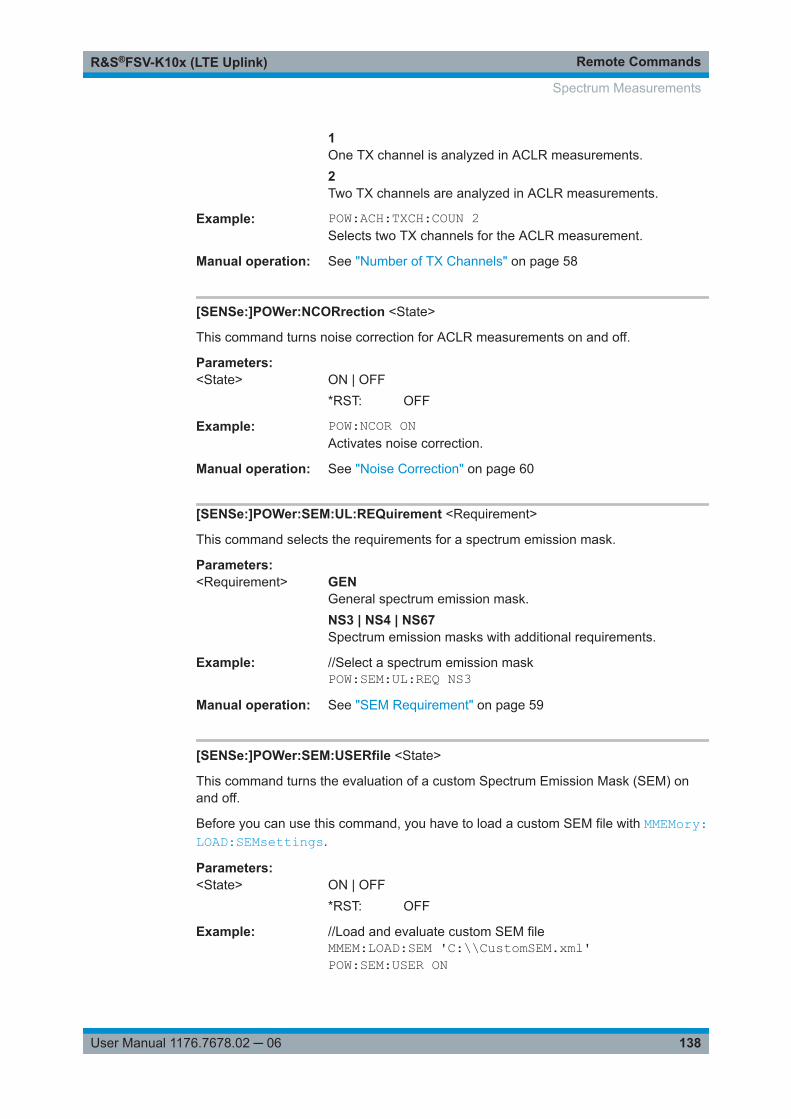
Remote CommandsR&S®FSV-K10x (LTE Uplink)
138User Manual 1176.7678.02 ─ 06
1One TX channel is analyzed in ACLR measurements.2Two TX channels are analyzed in ACLR measurements.
Example: POW:ACH:TXCH:COUN 2Selects two TX channels for the ACLR measurement.
Manual operation: See "Number of TX Channels" on page 58
[SENSe:]POWer:NCORrection <State>
This command turns noise correction for ACLR measurements on and off.
Parameters:<State> ON | OFF
*RST: OFF
Example: POW:NCOR ONActivates noise correction.
Manual operation: See "Noise Correction" on page 60
[SENSe:]POWer:SEM:UL:REQuirement <Requirement>
This command selects the requirements for a spectrum emission mask.
Parameters:<Requirement> GEN
General spectrum emission mask.NS3 | NS4 | NS67Spectrum emission masks with additional requirements.
Example: //Select a spectrum emission maskPOW:SEM:UL:REQ NS3
Manual operation: See "SEM Requirement" on page 59
[SENSe:]POWer:SEM:USERfile <State>
This command turns the evaluation of a custom Spectrum Emission Mask (SEM) onand off.
Before you can use this command, you have to load a custom SEM file with MMEMory:LOAD:SEMsettings.
Parameters:<State> ON | OFF
*RST: OFF
Example: //Load and evaluate custom SEM fileMMEM:LOAD:SEM 'C:\\CustomSEM.xml'POW:SEM:USER ON
Spectrum Measurements

Remote CommandsR&S®FSV-K10x (LTE Uplink)
139User Manual 1176.7678.02 ─ 06
Manual operation: See "User SEM File" on page 58
[SENSe:]SWEep:EGATe:AUTO <State>
This command turns auto gating for SEM and ACLR measurements on and off.
This command is available for TDD measurements in combination with an external orIF power trigger.
Parameters:<State> ON
Evaluates the on-period of the LTE signal only.OFFEvaluates the complete signal.
Example: SWE:EGAT:AUTO ONTurns auto gating on.
Manual operation: See "Auto Gating" on page 57
9.11 Signal Demodulation
● Configuring the Data Analysis...............................................................................139● Compensating Measurement Errors..................................................................... 142
9.11.1 Configuring the Data Analysis
[SENSe:][LTE:]UL:DEMod:ACON.................................................................................... 139[SENSe:][LTE:]UL:DEMod:CBSCrambling........................................................................ 140[SENSe:][LTE:]UL:DEMod:CDCoffset...............................................................................140[SENSe:][LTE:]UL:DEMod:CESTimation...........................................................................140[SENSe:][LTE:]UL:DEMod:MCFilter..................................................................................140[SENSe:][LTE:]UL:DEMod:MODE.................................................................................... 141[SENSe:][LTE:]UL:DEMod:SISYnc...................................................................................141[SENSe:][LTE:]UL:FORMat:SCD......................................................................................141
[SENSe:][LTE:]UL:DEMod:ACON <Type>
This command selects the method of automatic demodulation.
Parameters:<Type> ALL
Automatically detects and demodulates the PUSCH and SRS.OFFAutomatic demodulation is off.SCONAutomatically detects and demodulates the values available inthe subframe configuration table.
Signal Demodulation

Remote CommandsR&S®FSV-K10x (LTE Uplink)
140User Manual 1176.7678.02 ─ 06
Example: //Turn off automatic demodulation offUL:DEM:ACON OFF
Manual operation: See "Auto Demodulation" on page 64
[SENSe:][LTE:]UL:DEMod:CBSCrambling <State>
This command turns scrambling of coded bits on and off.
Parameters:<State> ON | OFF | 1 | 0
*RST: ON
Example: //Turn off descrambling of coded bitsUL:DEM:CBSC OFF
Manual operation: See "Scrambling of Coded Bits" on page 64
[SENSe:][LTE:]UL:DEMod:CDCoffset <State>
This command turns DC offset compensation on and off.
Parameters:<State> ON | OFF | 1 | 0
*RST: ON
Example: //Turn off DC offset compensationUL:DEM:CDC OFF
Manual operation: See "Compensate DC Offset" on page 64
[SENSe:][LTE:]UL:DEMod:CESTimation <Type>
This command selects the channel estimation type.
Parameters:<Type> PIL
Pilot onlyPILPPilot and payload*RST: PILP
Example: //Use the pilot signal for channel estimationUL:DEM:CEST PIL
Manual operation: See "Channel Estimation Range" on page 63
[SENSe:][LTE:]UL:DEMod:MCFilter <State>
This command turns suppression of interfering neighboring carriers on and off (forexample LTE, WCDMA, GSM etc.).
Signal Demodulation

Remote CommandsR&S®FSV-K10x (LTE Uplink)
141User Manual 1176.7678.02 ─ 06
Parameters:<State> ON | OFF | 1 | 0
*RST: OFF
Example: //Turn on interference suppressionUL:DEM:MCF ON
Manual operation: See "Multicarrier Filter" on page 65
[SENSe:][LTE:]UL:DEMod:MODE <Mode>
This command selects the uplink analysis mode.
Parameters:<Mode> PUSCh
Analyzes the PUSCH and PUCCH.PRAChAnalyzes the PRACH.*RST: PUSCh
Example: //Select PRACH analysis modeUL:DEM:MODE PRAC
Manual operation: See "Analysis Mode" on page 63
[SENSe:][LTE:]UL:DEMod:SISYnc <State>
This command turns suppressed interference synchronization on and off.
Parameters:<State> ON | OFF | 1 | 0
*RST: OFF
Example: //Turn on suppressed interference synchronizationUL:DEM:SISY ON
Manual operation: See "Suppressed Interference Synchronization" on page 65
[SENSe:][LTE:]UL:FORMat:SCD <State>
This command turns detection of the subframe configuration on and off.
Prerequisites for this command● Turn off auto demodulation [SENSe:][LTE:]UL:DEMod:ACONParameters:<State> ON | OFF | 1 | 0
*RST: OFF
Example: //Turn on automatic subframe configurationUL:FORM:SCD ON
Manual operation: See "Subframe Configuration Detection" on page 65
Signal Demodulation

Remote CommandsR&S®FSV-K10x (LTE Uplink)
142User Manual 1176.7678.02 ─ 06
9.11.2 Compensating Measurement Errors
[SENSe:][LTE:]UL:TRACking:PHASe............................................................................... 142[SENSe:][LTE:]UL:TRACking:TIME.................................................................................. 142
[SENSe:][LTE:]UL:TRACking:PHASe <Type>
This command selects the phase tracking method.
Parameters:<Type> OFF
Deactivate phase trackingPILPilot onlyPILPPilot and payload*RST: OFF
Example: //Use pilots and payload for channel estimationSENS:UL:TRAC:PHAS PILP
Manual operation: See "Phase" on page 66
[SENSe:][LTE:]UL:TRACking:TIME <State>
This command turns timing tracking on and off.
Parameters:<State> ON | OFF | 1 | 0
*RST: OFF
Example: //Turn on time trackingUL:TRAC:TIME ON
Manual operation: See "Timing" on page 66
9.12 Frame Configuration
● Configuring TDD Signals.......................................................................................142● Configuring the Physical Layer Cell Identity..........................................................143● Configuring Subframes......................................................................................... 145
9.12.1 Configuring TDD Signals
CONFigure[:LTE]:UL[:CC<cc>]:TDD:SPSC.......................................................................143CONFigure[:LTE]:UL[:CC<cc>]:TDD:UDConf.................................................................... 143
Frame Configuration

Remote CommandsR&S®FSV-K10x (LTE Uplink)
143User Manual 1176.7678.02 ─ 06
CONFigure[:LTE]:UL[:CC<cc>]:TDD:SPSC <Configuration>
This command selects the special TDD subframe configuration.
Suffix: <cc>
.irrelevant
Parameters:<Configuration> <numeric value>
Example: //Single carrier measurements://Select special subframe configurationCONF:UL:TDD:SPSC 2
Example: //Carrier aggregation measurements://Selects special subframe configuration for the first carrier.CONF:UL:CC1:TDD:SPSC 2
Manual operation: See "Conf. of Special Subframe" on page 67
CONFigure[:LTE]:UL[:CC<cc>]:TDD:UDConf <Configuration>
This command selects the subframe configuration for TDD signals.
Suffix: <cc>
.irrelevant
Parameters:<Configuration> <numeric value>
Range: 0 to 6*RST: 0
Example: //Single carrier measurements://Selects allocation configuration numberCONF:UL:TDD:UDC 4
Example: //Carrier aggregation measurements://Select allocation configuration number 4 for the first carrierCONF:UL:CC1:TDD:UDC 4
Manual operation: See "TDD UL/DL Allocations" on page 67
9.12.2 Configuring the Physical Layer Cell Identity
Commands to configure the physical layer cell ID described elsewhere.● FETCh[:CC<cc>]:PLC:CIDGroup?● FETCh[:CC<cc>]:PLC:PLID?CONFigure[:LTE]:UL[:CC<cc>]:PLC:CID.......................................................................... 144CONFigure[:LTE]:UL[:CC<cc>]:PLC:CIDGroup................................................................. 144CONFigure[:LTE]:UL[:CC<cc>]:PLC:PLID.........................................................................144
Frame Configuration

Remote CommandsR&S®FSV-K10x (LTE Uplink)
144User Manual 1176.7678.02 ─ 06
CONFigure[:LTE]:UL[:CC<cc>]:PLC:CID <CellID>
This command defines the cell ID.
Suffix: <cc>
.irrelevant
Parameters:<CellID> AUTO
Automatically determines the cell ID.<numeric value> (integer only)Number of the cell ID.Range: 0 to 503
Example: //Select automatic detection of the cell IDCONF:UL:PLC:CID AUTO
Manual operation: See "Configuring the Physical Layer Cell Identity" on page 68
CONFigure[:LTE]:UL[:CC<cc>]:PLC:CIDGroup <GroupNumber>
This command selects the cell identity group.
Suffix: <cc>
.irrelevant
Parameters:<GroupNumber> <numeric value> (integer only)
Range: 1 to 167*RST: 0
Example: //Select cell identity group 12CONF:UL:PLCI:CIDG 12
Manual operation: See "Configuring the Physical Layer Cell Identity" on page 68
CONFigure[:LTE]:UL[:CC<cc>]:PLC:PLID <Identity>
This command selects the physical layer identity.
Suffix: <cc>
.irrelevant
Parameters:<Identity> 0 | 1 | 2
Example: //Select physical layer identity 2CONF:DL:PLC:PLID 2
Manual operation: See "Configuring the Physical Layer Cell Identity" on page 68
Frame Configuration

Remote CommandsR&S®FSV-K10x (LTE Uplink)
145User Manual 1176.7678.02 ─ 06
9.12.3 Configuring Subframes
CONFigure[:LTE]:UL[:CC<cc>]:CSUBframes.................................................................... 145CONFigure[:LTE]:UL[:CC<cc>]:SFNO.............................................................................. 145CONFigure[:LTE]:UL[:CC<cc>]:SUBFrame<sf>:ALLoc[:CLUSter<cl>]:RBCount................... 145CONFigure[:LTE]:UL[:CC<cc>]:SUBFrame<sf>:ALLoc[:CLUSter<cl>]:RBOFfset.................. 146CONFigure[:LTE]:UL[:CC<cc>]:SUBFrame<sf>:ALLoc:CONT.............................................146CONFigure[:LTE]:UL[:CC<cc>]:SUBFrame<sf>:ALLoc:MODulation.....................................146
CONFigure[:LTE]:UL[:CC<cc>]:CSUBframes <Subframes>
This command selects the number of configurable subframes in the uplink signal.
Suffix: <cc>
.irrelevant
Parameters:<Subframes> Range: 1 to 10
*RST: 1
Example: //Define number of configurable subframesCONF:UL:CSUB 5
CONFigure[:LTE]:UL[:CC<cc>]:SFNO <Offset>
This command defines the system frame number offset.
The application uses the offset to demodulate the frame.
Suffix: <cc>
.irrelevant
Parameters:<Offset> <numeric value> (integer only)
*RST: 0
Example: //Select frame number offsetCONF:UL:SFNO 2
CONFigure[:LTE]:UL[:CC<cc>]:SUBFrame<sf>:ALLoc[:CLUSter<cl>]:RBCount<ResourceBlocks>
This command selects the number of resource blocks in an uplink subframe.
Suffix: <cc>
.irrelevant
<sf> Subframe
<cl> Cluster
Parameters:<ResourceBlocks> <numeric value>
*RST: 11
Frame Configuration

Remote CommandsR&S®FSV-K10x (LTE Uplink)
146User Manual 1176.7678.02 ─ 06
Example: //Select number of resource blocks for subframe 8CONF:UL:SUBF8:ALL:RBC 8
Manual operation: See "Number of RB" on page 70
CONFigure[:LTE]:UL[:CC<cc>]:SUBFrame<sf>:ALLoc[:CLUSter<cl>]:RBOFfset<Offset>
This command defines the resource block offset in an uplink subframe.
Suffix: <cc>
.irrelevant
<sf> Subframe
<cl> Cluster
Parameters:<Offset> <numeric value>
*RST: 2
Example: //Define resource block offsetCONF:UL:SUBF8:ALL:RBOF 5
Manual operation: See "Offset RB" on page 70
CONFigure[:LTE]:UL[:CC<cc>]:SUBFrame<sf>:ALLoc:CONT <AllocationContent>
This command allocates a PUCCH or PUSCH to an uplink allocation.
Suffix: <cc>
.irrelevant
<sf> Subframe
Parameters:<AllocationContent> NONE
Turns off the PUSCH and the PUCCH.PUCChTurns on the PUCCH.PUSChTurns on the PUSCH.PSCCTurns on the PUCCH as well as the PUSCH.*RST: PUSCh
Example: //Assign PUCCH allocation to a subframeCONF:UL:SUBF8:ALL:CONT PUCC
Manual operation: See "Enable PUCCH" on page 70
CONFigure[:LTE]:UL[:CC<cc>]:SUBFrame<sf>:ALLoc:MODulation <Modulation>
This command selects the modulation of an uplink allocation.
Frame Configuration

Remote CommandsR&S®FSV-K10x (LTE Uplink)
147User Manual 1176.7678.02 ─ 06
Suffix: <cc>
.irrelevant
<sf> Subframe
Parameters:<Modulation> QPSK | QAM16 | QAM64 | QAM256
*RST: QPSK
Example: //Define modulation of the allocation in subframe 8CONF:UL:SUBF8:ALL:MOD QPSK
Manual operation: See "Modulation" on page 70
9.13 Advanced Signal Characteristics
● Configuring the Demodulation Reference Signal..................................................147● Configuring the Sounding Reference Signal.........................................................149● Defining the PUSCH Structure..............................................................................152● Defining the PUCCH Structure..............................................................................154● Defining Global Signal Characteristics..................................................................156
9.13.1 Configuring the Demodulation Reference Signal
CONFigure[:LTE]:UL[:CC<cc>]:DRS:DSSHift....................................................................147CONFigure[:LTE]:UL[:CC<cc>]:DRS:GRPHopping............................................................ 147CONFigure[:LTE]:UL[:CC<cc>]:DRS:NDMRs.................................................................... 148CONFigure[:LTE]:UL[:CC<cc>]:DRS:PUCCh:POWer.........................................................148CONFigure[:LTE]:UL[:CC<cc>]:DRS[:PUSCh]:POWer....................................................... 148CONFigure[:LTE]:UL[:CC<cc>]:DRS:SEQHopping............................................................ 149
CONFigure[:LTE]:UL[:CC<cc>]:DRS:DSSHift <Shift>
This command selects the delta sequence shift of the uplink signal.
Suffix: <cc>
.irrelevant
Parameters:<Shift> <numeric value> (integer only)
*RST: 0
Example: //Select delta sequence shiftCONF:UL:DRS:DSSH 3
Manual operation: See " Delta Sequence Shift" on page 72
CONFigure[:LTE]:UL[:CC<cc>]:DRS:GRPHopping <State>
This command turns group hopping for uplink signals on and off.
Advanced Signal Characteristics
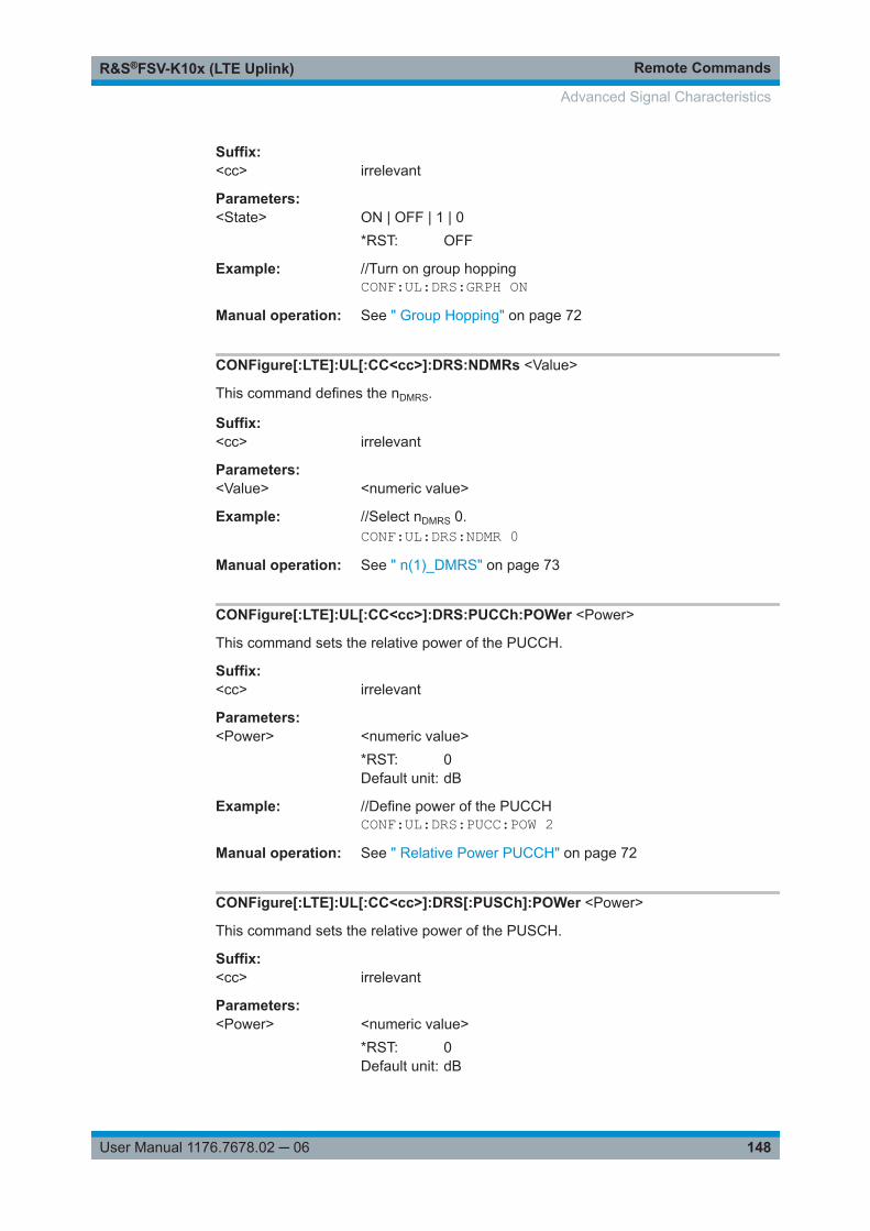
Remote CommandsR&S®FSV-K10x (LTE Uplink)
148User Manual 1176.7678.02 ─ 06
Suffix: <cc>
.irrelevant
Parameters:<State> ON | OFF | 1 | 0
*RST: OFF
Example: //Turn on group hoppingCONF:UL:DRS:GRPH ON
Manual operation: See " Group Hopping" on page 72
CONFigure[:LTE]:UL[:CC<cc>]:DRS:NDMRs <Value>
This command defines the nDMRS.
Suffix: <cc>
.irrelevant
Parameters:<Value> <numeric value>
Example: //Select nDMRS 0.CONF:UL:DRS:NDMR 0
Manual operation: See " n(1)_DMRS" on page 73
CONFigure[:LTE]:UL[:CC<cc>]:DRS:PUCCh:POWer <Power>
This command sets the relative power of the PUCCH.
Suffix: <cc>
.irrelevant
Parameters:<Power> <numeric value>
*RST: 0Default unit: dB
Example: //Define power of the PUCCHCONF:UL:DRS:PUCC:POW 2
Manual operation: See " Relative Power PUCCH" on page 72
CONFigure[:LTE]:UL[:CC<cc>]:DRS[:PUSCh]:POWer <Power>
This command sets the relative power of the PUSCH.
Suffix: <cc>
.irrelevant
Parameters:<Power> <numeric value>
*RST: 0Default unit: dB
Advanced Signal Characteristics

Remote CommandsR&S®FSV-K10x (LTE Uplink)
149User Manual 1176.7678.02 ─ 06
Example: //Define power of the PUSCHCONF:UL:DRS:POW 2
Manual operation: See " Relative Power PUSCH" on page 72
CONFigure[:LTE]:UL[:CC<cc>]:DRS:SEQHopping <State>
This command turns sequence hopping for uplink signals on and off.
Suffix: <cc>
.irrelevant
Parameters:<State> ON | OFF | 1 | 0
*RST: OFF
Example: //Turn on sequence hoppingCONF:UL:DRS:SEQH ON
Manual operation: See " Sequence Hopping" on page 72
9.13.2 Configuring the Sounding Reference Signal
CONFigure[:LTE]:UL[:CC<cc>]:SRS:BHOP...................................................................... 149CONFigure[:LTE]:UL[:CC<cc>]:SRS:BSRS.......................................................................149CONFigure[:LTE]:UL[:CC<cc>]:SRS:CSRS.......................................................................150CONFigure[:LTE]:UL[:CC<cc>]:SRS:CYCS.......................................................................150CONFigure[:LTE]:UL[:CC<cc>]:SRS:ISRS........................................................................ 150CONFigure[:LTE]:UL[:CC<cc>]:SRS:NRRC...................................................................... 151CONFigure[:LTE]:UL[:CC<cc>]:SRS:POWer..................................................................... 151CONFigure[:LTE]:UL[:CC<cc>]:SRS:STAT........................................................................151CONFigure[:LTE]:UL[:CC<cc>]:SRS:SUConfig..................................................................152CONFigure[:LTE]:UL[:CC<cc>]:SRS:TRComb...................................................................152
CONFigure[:LTE]:UL[:CC<cc>]:SRS:BHOP <Bandwidth>
This command defines the frequency hopping bandwidth bhop.
Suffix: <cc>
.irrelevant
Parameters:<Bandwidth> <numeric value>
*RST: 0
Example: //Define frequency hopping bandwidthCONF:UL:SRS:BHOP 1
Manual operation: See " Hopping BW b_hop" on page 75
CONFigure[:LTE]:UL[:CC<cc>]:SRS:BSRS <Bandwidth>
This command defines the bandwidth of the SRS (BSRS).
Advanced Signal Characteristics

Remote CommandsR&S®FSV-K10x (LTE Uplink)
150User Manual 1176.7678.02 ─ 06
Suffix: <cc>
.irrelevant
Parameters:<Bandwidth> <numeric value>
*RST: 0
Example: //Select SRS bandwidthCONF:UL:SRS:BSRS 1
Manual operation: See " SRS Bandwidth B_SRS" on page 74
CONFigure[:LTE]:UL[:CC<cc>]:SRS:CSRS <Configuration>
This command defines the SRS bandwidth configuration (CSRS).
Suffix: <cc>
.irrelevant
Parameters:<Configuration> <numeric value>
*RST: 0
Example: //Select SRS bandwidth configurationCONF:UL:SRS:CSRS 2
Manual operation: See " SRS BW Conf. C_SRS" on page 74
CONFigure[:LTE]:UL[:CC<cc>]:SRS:CYCS <CyclicShift>
Sets the cyclic shift n_CS used for the generation of the sounding reference signalCAZAC sequence.
Suffix: <cc>
.irrelevant
Parameters:<CyclicShift> <numeric value>
*RST: 0
Example: //Select cyclic shiftCONF:UL:SRS:CYCS 2
Manual operation: See " SRS Cyclic Shift N_CS" on page 75
CONFigure[:LTE]:UL[:CC<cc>]:SRS:ISRS <Index>
This command defines the SRS configuration index (ISRS).
Suffix: <cc>
.irrelevant
Parameters:<Index> <numeric value>
*RST: 0
Advanced Signal Characteristics

Remote CommandsR&S®FSV-K10x (LTE Uplink)
151User Manual 1176.7678.02 ─ 06
Example: //Select configuration indexCONF:UL:SRS:ISRS 1
Manual operation: See " Conf. Index I_SRS" on page 75
CONFigure[:LTE]:UL[:CC<cc>]:SRS:NRRC <Value>
This command defines the UE-specific parameter frequency domain position nRRC.
Suffix: <cc>
.irrelevant
Parameters:<Value> <numeric value>
*RST: 0
Example: //Select nRRC
CONF:UL:SRS:NRRC 1Manual operation: See " Freq. Domain Pos. n_RRC" on page 74
CONFigure[:LTE]:UL[:CC<cc>]:SRS:POWer <Power>
Defines the relative power of the sounding reference signal.
Suffix: <cc>
.irrelevant
Parameters:<Power> <numeric value>
*RST: 0
Example: //Define the power of sounding reference signalCONF:UL:SRS:POW -1.2
Manual operation: See " SRS Rel Power" on page 74
CONFigure[:LTE]:UL[:CC<cc>]:SRS:STAT <State>
Turns the sounding reference signal on and off.
Suffix: <cc>
.irrelevant
Parameters:<State> ON | OFF | 1 | 0
*RST: OFF
Example: //Turn on the sounding reference signalCONF:UL:SRS:STAT ON
Manual operation: See " Present" on page 73
Advanced Signal Characteristics

Remote CommandsR&S®FSV-K10x (LTE Uplink)
152User Manual 1176.7678.02 ─ 06
CONFigure[:LTE]:UL[:CC<cc>]:SRS:SUConfig <Configuration>
This command defines the SRS subframe configuration.
Prerequisites for this command● Turn on the sounding reference signal with CONFigure[:LTE]:UL[:CC<cc>]:
SRS:STAT.
Suffix: <cc>
.irrelevant
Parameters:<Configuration> <numeric value> (integer only)
Range: 0 to 14*RST: 0
Example: //Select SRS subframe configuration 4CONF:UL:SRS:SUC 4
Manual operation: See " SRS Subframe Configuration" on page 74
CONFigure[:LTE]:UL[:CC<cc>]:SRS:TRComb <Value>
This command defines the transmission comb (kTC).
Suffix: <cc>
.irrelevant
Parameters:<Value> <numeric value>
*RST: 0
Example: //Define transmission combCONF:UL:SRS:TRC 1
Manual operation: See " Transm. Comb. k_TC" on page 75
9.13.3 Defining the PUSCH Structure
CONFigure[:LTE]:UL[:CC<cc>]:PUSCh:FHMode............................................................... 152CONFigure[:LTE]:UL[:CC<cc>]:PUSCh:FHOFfset............................................................. 153CONFigure[:LTE]:UL[:CC<cc>]:PUSCh:FHOP:IIHB........................................................... 153CONFigure[:LTE]:UL[:CC<cc>]:PUSCh:NOSM..................................................................153
CONFigure[:LTE]:UL[:CC<cc>]:PUSCh:FHMode <HoppingMode>
This command selects the frequency hopping mode in the PUSCH structure.
Suffix: <cc>
.irrelevant
Parameters:<HoppingMode> NONE
No hopping
Advanced Signal Characteristics

Remote CommandsR&S®FSV-K10x (LTE Uplink)
153User Manual 1176.7678.02 ─ 06
INTerInter subframe hoppingINTRaIntra subframe hopping*RST: NONE
Example: //Turn off frequency hopping for PUSCHCONF:UL:PUSC:FHM NONE
Manual operation: See " Frequency Hopping Mode" on page 76
CONFigure[:LTE]:UL[:CC<cc>]:PUSCh:FHOFfset <Offset>
This command defines the frequency hopping offset for the PUSCH.
Suffix: <cc>
.irrelevant
Parameters:<Offset> <numeric value>
*RST: 4
Example: //Define a hopping offsetCONF:UL:PUSC:FHOF 5
Manual operation: See " PUSCH Hopping Offset" on page 76
CONFigure[:LTE]:UL[:CC<cc>]:PUSCh:FHOP:IIHB <HBInfo>
This command defines the information in hopping bits of the PUSCH.
Suffix: <cc>
.irrelevant
Parameters:<HBInfo> <numeric value>
Range: 0 to 3*RST: 0
Example: //Select information in hopping bitsCONF:UL:PUSC:FHOP:IIHB 1
Manual operation: See " Info. in Hopping Bits" on page 77
CONFigure[:LTE]:UL[:CC<cc>]:PUSCh:NOSM <NoOfSubbands>
This command defines the number of subbands/M of the PUSCH.
Suffix: <cc>
.irrelevant
Parameters:<NoOfSubbands> <numeric value>
*RST: 4
Advanced Signal Characteristics

Remote CommandsR&S®FSV-K10x (LTE Uplink)
154User Manual 1176.7678.02 ─ 06
Example: //Select number of subbandsCONF:UL:PUSC:NOSM 2
Manual operation: See " Number of Subbands" on page 76
9.13.4 Defining the PUCCH Structure
CONFigure[:LTE]:UL[:CC<cc>]:PUCCh:DESHift................................................................154CONFigure[:LTE]:UL[:CC<cc>]:PUCCh:FORMat............................................................... 154CONFigure[:LTE]:UL[:CC<cc>]:PUCCh:N1CS...................................................................155CONFigure[:LTE]:UL[:CC<cc>]:PUCCh:N2RB...................................................................155CONFigure[:LTE]:UL[:CC<cc>]:PUCCh:NORB..................................................................155CONFigure[:LTE]:UL[:CC<cc>]:PUCCh:NPAR.................................................................. 156
CONFigure[:LTE]:UL[:CC<cc>]:PUCCh:DESHift <Shift>
This command defines the delta shift of the PUCCH.
Suffix: <cc>
.irrelevant
Parameters:<Shift> <numeric value>
Range: 1 to 3*RST: 2
Example: //Select a delta shift for the PUCCHCONF:UL:PUCC:DESH 3
Manual operation: See " Delta Shift" on page 78
CONFigure[:LTE]:UL[:CC<cc>]:PUCCh:FORMat <Format>
This command selects the PUCCH format.
Note that formats 2a and 2b are available for normal cyclic prefix length only.
Suffix: <cc>
.irrelevant
Parameters:<Format> F1 (F1)
F1A (F1a)F1B (F1b)F2 (F2)F2A (F2a)F2B (F2b)F3 (F3)*RST: F1
Example: //Select PUCCH formatCONF:UL:PUCC:FORM F1B
Advanced Signal Characteristics

Remote CommandsR&S®FSV-K10x (LTE Uplink)
155User Manual 1176.7678.02 ─ 06
Manual operation: See " Format" on page 78
CONFigure[:LTE]:UL[:CC<cc>]:PUCCh:N1CS <Value>
This command defines the N(1)_cs of the PUCCH.
Suffix: <cc>
.irrelevant
Parameters:<Value> <numeric value> (integer only)
*RST: 6
Example: //Select N(1)_csCONF:UL:PUCC:N1CS 4
Manual operation: See " N(1)_cs" on page 78
CONFigure[:LTE]:UL[:CC<cc>]:PUCCh:N2RB <Value>
This command defines the N(2)_RB of the PUCCH.
Suffix: <cc>
.irrelevant
Parameters:<Value> <numeric value> (integer only)
*RST: 1
Example: //Define N2_RBCONF:UL:PUCC:N2RB 2
Manual operation: See " N(2)_RB" on page 78
CONFigure[:LTE]:UL[:CC<cc>]:PUCCh:NORB <ResourceBlocks>
This command selects the number of resource blocks for the PUCCH.
Suffix: <cc>
.irrelevant
Parameters:<ResourceBlocks> <numeric value>
Selects the number of RBs.AUTODetects the number of RBs automatically.*RST: 0
Example: //Define number of resource blocks for PUCCHCONF:UL:PUCC:NORB 6
Manual operation: See " No. of RBs for PUCCH" on page 77
Advanced Signal Characteristics

Remote CommandsR&S®FSV-K10x (LTE Uplink)
156User Manual 1176.7678.02 ─ 06
CONFigure[:LTE]:UL[:CC<cc>]:PUCCh:NPAR <Value>
This command defines the N_PUCCH parameter in the PUCCH structure settings.
Suffix: <cc>
.irrelevant
Parameters:<Value> <numeric value>
<numeric value>SUBFSelects the definition of N_PUCCH on subframe level.*RST: 0
Example: //Select N_PUCCHCONF:UL:PUCC:NPAR 2
Manual operation: See " N_PUCCH" on page 79
9.13.5 Defining Global Signal Characteristics
CONFigure[:LTE]:UL[:CC<cc>]:UEID............................................................................... 156
CONFigure[:LTE]:UL[:CC<cc>]:UEID <ID>
This command defines the radio network temporary identifier (RNTI) of the UE.
Suffix: <cc>
.irrelevant
Parameters:<ID> <numeric value> (integer only)
Range: 0 to 65535*RST: 0
Example: //Define a RNTI of 2CONF:UL:UEID 2
Manual operation: See "UE ID/n_RNTI" on page 79
9.14 PRACH Structure
CONFigure[:LTE]:UL[:CC<cc>]:PRACh:APM.................................................................... 157CONFigure[:LTE]:UL[:CC<cc>]:PRACh:CONF.................................................................. 157CONFigure[:LTE]:UL[:CC<cc>]:PRACh:FOFFset...............................................................157CONFigure[:LTE]:UL[:CC<cc>]:PRACh:FRINdex...............................................................157CONFigure[:LTE]:UL[:CC<cc>]:PRACh:HFINdicator.......................................................... 158CONFigure[:LTE]:UL[:CC<cc>]:PRACh:NCSC.................................................................. 158CONFigure[:LTE]:UL[:CC<cc>]:PRACh:RSEQ.................................................................. 158CONFigure[:LTE]:UL[:CC<cc>]:PRACh:RSET...................................................................159CONFigure[:LTE]:UL[:CC<cc>]:PRACh:SINDex................................................................ 159
PRACH Structure

Remote CommandsR&S®FSV-K10x (LTE Uplink)
157User Manual 1176.7678.02 ─ 06
CONFigure[:LTE]:UL[:CC<cc>]:PRACh:APM <State>
This command turns automatic preamble mapping for the PRACH on and off.
Suffix: <cc>
.irrelevant
Parameters:<State> ON | OFF | 1 | 0
Example: //Turn automatic preamble mapping on.CONF:UL:PRAC:APM ON
Manual operation: See "PRACH Preamble Mapping" on page 81
CONFigure[:LTE]:UL[:CC<cc>]:PRACh:CONF <Configuration>
This command selects the PRACH preamble format.
Suffix: <cc>
.irrelevant
Parameters:<Configuration> <numeric value> (integer only)
Example: //Select PRACH configuration 2CONF:UL:PRAC:CONF 2
Manual operation: See "PRACH Configuration" on page 80
CONFigure[:LTE]:UL[:CC<cc>]:PRACh:FOFFset <Offset>
This command defines the PRACH frequency offset.
The command is available for preamble formats 0 to 3.
Suffix: <cc>
.irrelevant
Parameters:<Offset> <numeric value> (integer only)
Frequency offset in terms of resource blocks.*RST: 0
Example: //Define a frequency offsetCONF:UL:PRAC:FOFF 5
Manual operation: See "Frequency Offset" on page 80
CONFigure[:LTE]:UL[:CC<cc>]:PRACh:FRINdex <FrequencyIndex>
This command selects the PRACH frequency index.
Suffix: <cc>
.irrelevant
PRACH Structure

Remote CommandsR&S®FSV-K10x (LTE Uplink)
158User Manual 1176.7678.02 ─ 06
Parameters:<FrequencyIndex> <numeric value> (integer only)
Example: //Select the frequency indexCONF:UL:PRAC:FRIN 10
Manual operation: See "PRACH Preamble Mapping" on page 81
CONFigure[:LTE]:UL[:CC<cc>]:PRACh:HFINdicator <Indicator>
This command defines the PRACH half frame indicator.
Suffix: <cc>
.irrelevant
Parameters:<Indicator> <numeric value>
Default unit: dB
Example: //Select half frame indicatorCONF:UL:PRAC:HFIN 5
Manual operation: See "PRACH Preamble Mapping" on page 81
CONFigure[:LTE]:UL[:CC<cc>]:PRACh:NCSC <Configuration>
This command defines the Ncs configuration for the PRACH.
Suffix: <cc>
.irrelevant
Parameters:<Configuration> <numeric value> (integer only)
Example: //Selects Ncs configurationCONF:UL:PRAC:NCSC 1
Manual operation: See "Ncs Conf" on page 80
CONFigure[:LTE]:UL[:CC<cc>]:PRACh:RSEQ <Index>
This command defines the PRACH logical root sequence index.
Suffix: <cc>
.irrelevant
Parameters:<Index> <numeric value> (integer only)
Example: //Select logical root sequence indexCONF:UL:PRAC:RSEQ 2
Manual operation: See "Logical Root Sequ. Idx" on page 80
PRACH Structure

Remote CommandsR&S®FSV-K10x (LTE Uplink)
159User Manual 1176.7678.02 ─ 06
CONFigure[:LTE]:UL[:CC<cc>]:PRACh:RSET <State>
This command turns the restricted preamble set for PRACH on and off.
Suffix: <cc>
.irrelevant
Parameters:<State> ON | OFF | 1 | 0
*RST: OFF
Example: //Turn on restricted setCONF:UL:PRAC:RSET ON
Manual operation: See "Restricted Set" on page 80
CONFigure[:LTE]:UL[:CC<cc>]:PRACh:SINDex <Index>
This command selects the PRACH sequence index.
Suffix: <cc>
.irrelevant
Parameters:<Index> <IndexValue>
Number that defines the index manually.AUTOAutomatically determines the index.
Example: //Select sequence indexCONF:UL:PRAC:SIND 2
Manual operation: See "Sequence Index (v)" on page 80
9.15 Measurement Result Analysis
● Selecting Displayed Data......................................................................................159● Selecting Units...................................................................................................... 162● Using Markers.......................................................................................................163● Using Delta Markers..............................................................................................166● Scaling the Vertical Diagram Axis......................................................................... 168
9.15.1 Selecting Displayed Data
[SENSe:][LTE:][CC<cc>:]ALLocation:SELect.....................................................................160[SENSe:][LTE:][CC<cc>:]CARRier:SELect........................................................................ 160[SENSe:][LTE:][CC<cc>:]MODulation:SELect....................................................................160[SENSe:][LTE:][CC<cc>:]PREamble:SELect..................................................................... 161[SENSe:][LTE:][CC<cc>:]SLOT:SELect.............................................................................161[SENSe:][LTE:][CC<cc>:]SUBFrame:SELect.....................................................................162[SENSe:][LTE:][CC<cc>:]SYMBol:SELect......................................................................... 162
Measurement Result Analysis

Remote CommandsR&S®FSV-K10x (LTE Uplink)
160User Manual 1176.7678.02 ─ 06
[SENSe:][LTE:][CC<cc>:]ALLocation:SELect <Allocation>
This command filters the displayed results in the constellation diagram by a certaintype of allocation.
Suffix: <cc>
.irrelevant
Parameters:<Allocation> ALL
Shows the results for all allocations.<numeric_value> (integer only)Shows the results for a single allocation type.Allocation types are mapped to numeric values. For the codeassignment, see Chapter 9.6.1.18, "Return Value Codes",on page 119.*RST: ALL
Example: //Display results for PUSCHALL:SEL -40
Manual operation: See "Evaluation range for the constellation diagram" on page 85
[SENSe:][LTE:][CC<cc>:]CARRier:SELect <Carrier>
This command filters the results in the constellation diagram by a certain subcarrier.
Suffix: <cc>
.irrelevant
Parameters:<Carrier> ALL
Shows the results for all subcarriers.<numeric_value> (integer only)Shows the results for a single subcarrier.*RST: ALL
Example: //Display results for subcarrier 1CARR:SEL 1
Manual operation: See "Evaluation range for the constellation diagram" on page 85
[SENSe:][LTE:][CC<cc>:]MODulation:SELect <Modulation>
This command filters the results in the constellation diagram by a certain type of modu-lation.
Suffix: <cc>
.irrelevant
Parameters:<Modulation> ALL
Shows the results for all modulation types.
Measurement Result Analysis

Remote CommandsR&S®FSV-K10x (LTE Uplink)
161User Manual 1176.7678.02 ─ 06
<numeric_value> (integer only)Shows the results for a single modulation type.Modulation types are mapped to numeric values. For the codeassignment, see Chapter 9.6.1.18, "Return Value Codes",on page 119.*RST: ALL
Example: //Display results for all elements with a QPSK modulationMOD:SEL 2
Manual operation: See "Evaluation range for the constellation diagram" on page 85
[SENSe:][LTE:][CC<cc>:]PREamble:SELect <Preamble>
This command selects a certain preamble for measurements that analyze individualpreambles.
Prerequisites for this command● Select PRACH analysis mode ([SENSe:][LTE:]UL:DEMod:MODE on page 141).
Suffix: <cc>
.irrelevant
Parameters:<Preamble> ALL
Analyzes all preambles.<numeric value> (integer only)Analyzes a single preamble.*RST: ALL
Example: //Analyze all preamblesPRE:SEL ALL
Manual operation: See "Preamble Selection" on page 84
[SENSe:][LTE:][CC<cc>:]SLOT:SELect <Slot>
This command filters the results in the constellation diagram by a particular slot.
Suffix: <cc>
.irrelevant
Parameters:<Slot> S0
Slot 0S1Slot 1ALLBoth slots*RST: ALL
Example: //Display results for all slotsSLOT:SEL ALL
Measurement Result Analysis

Remote CommandsR&S®FSV-K10x (LTE Uplink)
162User Manual 1176.7678.02 ─ 06
Manual operation: See "Slot Selection" on page 83
[SENSe:][LTE:][CC<cc>:]SUBFrame:SELect <Subframe>
This command selects the subframe to be analyzed.
Suffix: <cc>
.irrelevant
Parameters:<Subframe> ALL | <numeric value>
ALLSelect all subframes0...39Select a single subframe*RST: ALL
Example: //Display results for all subframesSUBF:SEL ALL
Manual operation: See "Subframe Selection" on page 82
[SENSe:][LTE:][CC<cc>:]SYMBol:SELect <Symbol>
This command filters the results in the constellation diagram by a certain OFDM sym-bol.
Suffix: <cc>
.irrelevant
Parameters:<Symbol> ALL
Shows the results for all subcarriers.<numeric_value> (integer only)Shows the results for a single OFDM symbol.*RST: ALL
Example: //Display result for OFDM symbol 2SYMB:SEL 2
Manual operation: See "Evaluation range for the constellation diagram" on page 85
9.15.2 Selecting Units
UNIT:BSTR....................................................................................................................163UNIT:EVM..................................................................................................................... 163
Measurement Result Analysis

Remote CommandsR&S®FSV-K10x (LTE Uplink)
163User Manual 1176.7678.02 ─ 06
UNIT:BSTR <Unit>
This command selects the way the bit stream is displayed.
Parameters:<Unit> SYMbols
Displays the bit stream using symbolsBITsDisplays the bit stream using bits*RST: SYMbols
Example: //Display bit stream as bitsUNIT:BSTR BIT
Manual operation: See "Bit Stream Format" on page 84
UNIT:EVM <Unit>
This command selects the EVM unit.
Parameters:<Unit> DB
EVM results returned in dBPCTEVM results returned in %*RST: PCT
Example: //Display EVM results in %UNIT:EVM PCT
Manual operation: See "EVM Unit" on page 84
9.15.3 Using Markers
CALCulate<n>:MARKer<m>:AOFF..................................................................................163CALCulate<n>:MARKer<m>:MAXimum[:PEAK]................................................................ 164CALCulate<n>:MARKer<m>:MINimum[:PEAK]................................................................. 164CALCulate<n>:MARKer<m>[:STATe]............................................................................... 164CALCulate<n>:MARKer<m>:TRACe................................................................................164CALCulate<n>:MARKer<m>:X........................................................................................ 165CALCulate<n>:MARKer<m>:Y........................................................................................ 165
CALCulate<n>:MARKer<m>:AOFF
This command turns all markers and delta markers off.
Suffix: <n>
.1..n
<m> 1..n
Example: CALC:MARK:AOFFTurns off all markers.
Measurement Result Analysis

Remote CommandsR&S®FSV-K10x (LTE Uplink)
164User Manual 1176.7678.02 ─ 06
Usage: Event
CALCulate<n>:MARKer<m>:MAXimum[:PEAK]
This command positions a marker on the peak value of the trace.
Suffix: <n>
.Window
<m> Marker
Example: //Position marker 2 on the peak valueCALC:MARK2:MAX
Usage: Event
CALCulate<n>:MARKer<m>:MINimum[:PEAK]
This command positions a marker on the minimum value of the trace.
Suffix: <n>
.Window
<m> Marker
Example: //Position marker 1 on the minimum valueCALC:MARK:MIN
Usage: Event
CALCulate<n>:MARKer<m>[:STATe] <State>
This command turns markers on and off.
Suffix: <n>
.Window
<m> Marker
Parameters:<State> ON | OFF
*RST: OFF
Example: //Turn on a markerCALC:MARK3 ON
CALCulate<n>:MARKer<m>:TRACe <Trace>
This command positions the marker on a particular trace.
If necessary, the command turns on the marker first.
Suffix: <n>
.Window
Measurement Result Analysis
Remote CommandsR&S®FSV-K10x (LTE Uplink)
165User Manual 1176.7678.02 ─ 06
<m> Marker
Parameters:<Trace> 1 | 2 | 3
Number of the trace you want the marker positioned on.
Example: //Position marker on a traceCALC:MARK3:TRAC 2
CALCulate<n>:MARKer<m>:X <Position>
This command positions a marker on a particular coordinate on the x-axis.
If necessary, the command first turns on the marker.
Suffix: <n>
.Window
<m> Marker
Parameters:<Position> Numeric value that defines the marker position on the x-axis.
Default unit: The unit depends on the result display.
Example: //Move a marker to the frequency of 1 GHzCALC:MARK:X 1GHZ
CALCulate<n>:MARKer<m>:Y <Result>
This command queries the position of a marker on the y-axis.
If necessary, the command activates the marker first.
To get a valid result, you have to perform a complete measurement with synchroniza-tion to the end of the measurement before reading out the result. This is only possiblefor single sweeps.
Suffix: <n>
.Window
<m> Marker
Parameters:<Result>
Example: //Select a single measurementINIT:CONT OFF//Start a measurement and waits until it is doneINIT;*WAI//Turn on a marker and query its position on the y-axisCALC:MARK2 ONCALC:MARK2:Y?
Measurement Result Analysis

Remote CommandsR&S®FSV-K10x (LTE Uplink)
166User Manual 1176.7678.02 ─ 06
9.15.4 Using Delta Markers
CALCulate<n>:DELTamarker<m>:AOFF...........................................................................166CALCulate<n>:DELTamarker<m>:MAXimum[:PEAK].........................................................166CALCulate<n>:MARKer<m>:MINimum[:PEAK]................................................................. 166CALCulate<n>:DELTamarker<m>[:STATe]........................................................................ 166CALCulate<n>:DELTamarker<m>:TRACe.........................................................................167CALCulate<n>:DELTamarker<m>:X.................................................................................167CALCulate<n>:DELTamarker<m>:Y?............................................................................... 167
CALCulate<n>:DELTamarker<m>:AOFF
This command turns all delta markers off.
Suffix: <m>
.1
Example: CALC:DELT:AOFFTurns off all delta markers.
Usage: Event
CALCulate<n>:DELTamarker<m>:MAXimum[:PEAK]
This command positions a marker on the peak value of the trace.
Suffix: <m>
.1..n
Example: CALC:DELT2:MAXPositions delta marker 2 on the trace peak.
Usage: Event
CALCulate<n>:MARKer<m>:MINimum[:PEAK]
This command positions a delta marker on the minimum value of the trace.
Suffix: <m>
.1..n
Example: CALC:DELT2:MINPositions delta marker 2 on the trace minimum.
Usage: Event
CALCulate<n>:DELTamarker<m>[:STATe] <State>
This command turns delta markers on and off.
Suffix: <m>
.1
Measurement Result Analysis

Remote CommandsR&S®FSV-K10x (LTE Uplink)
167User Manual 1176.7678.02 ─ 06
Parameters:<State> ON | OFF
*RST: OFF
Example: CALC:DELT3 ONTurns on delta marker 3.
CALCulate<n>:DELTamarker<m>:TRACe <Trace>
This command positions a delta marker on a particular trace.
Suffix: <m>
.1
Parameters:<Trace> 1 | 2 | 3
Number of the trace you want the delta marker positioned on.
CALCulate<n>:DELTamarker<m>:X <Position>
This command positions a delta marker on a particular coordinate on the x-axis.
If necessary, the command first turns on the delta marker.
Suffix: <m>
.1
Parameters:<Position> Numeric value that defines the delta marker position on the x-
axis.Default unit: The unit depends on the result display.
Example: CALC:DELT2:X 1GHZPositions delta marker 2 on the frequency of 1 GHz.
CALCulate<n>:DELTamarker<m>:Y?
This command queries the position of a delta marker on the y-axis.
If necessary, the command activates the delta marker first.
To get a valid result, you have to perform a complete measurement with synchroniza-tion to the end of the measurement before reading out the result. This is only possiblefor single sweeps.
Suffix: <m>
.1
Measurement Result Analysis

Remote CommandsR&S®FSV-K10x (LTE Uplink)
168User Manual 1176.7678.02 ─ 06
Example: INIT:CONT OFFSwitches to single measurement mode.CALC:DELT2 ONTurns on delta marker 2.INIT;*WAIStarts a measurement and waits for the end.CALC:MARK2:Y?Queries the measurement result at the position of delta marker2.
Usage: Query only
9.15.5 Scaling the Vertical Diagram Axis
Programming example to scale the y-axis
//Start EVM vs Symbol result display in screen B.CALC2:FEED 'EVM:EVSY'//Refresh the measurement results based on the contents of the capture bufferINIT:IMM//Select screen B.DISP:WIND2:SEL//Select dB as the EVM unit.UNIT:EVM DB//Define the point of origin of 5 dB on the y-axis.DISP:TRAC:Y:SCAL:FIXS:OFFS 5//Define the distance of 10 dB between two grid lines on the y-axis.DISP:TRAC:Y:SCAL:FIXS:PERD 10
DISPlay[:WINDow]:TRACe:Y:SCALe:AUTO......................................................................168DISPlay[:WINDow]:TRACe:Y:SCALe:FIXScale:OFFSet..................................................... 169DISPlay[:WINDow]:TRACe:Y:SCALe:FIXScale:PERDiv..................................................... 169
DISPlay[:WINDow]:TRACe:Y:SCALe:AUTO
This command automatically adjusts the scale of the y-axis to the current measure-ment results.
Note that the command only affects the result display selected with DISPlay[:WINDow<n>]:SELect.
Example: DISP:TRAC:Y:SCAL:AUTOScales the y-axis of the selected result display.
Usage: Event
Manual operation: See "Y-Axis Scale" on page 86
Measurement Result Analysis
Remote CommandsR&S®FSV-K10x (LTE Uplink)
169User Manual 1176.7678.02 ─ 06
DISPlay[:WINDow]:TRACe:Y:SCALe:FIXScale:OFFSet <Origin>
This command defines the point of origin of the y-axis and thus has an effect on thescale of the y-axis.
Note that the command only affects the result display selected with DISPlay[:WINDow<n>]:SELect.
Parameters:<Origin> Point of origin of the y-axis.
The unit depends on the result display you want to scale.
Example: See Chapter 9.15, "Measurement Result Analysis",on page 159.
Manual operation: See "Y-Axis Scale" on page 86
DISPlay[:WINDow]:TRACe:Y:SCALe:FIXScale:PERDiv <Distance>
This command defines the distance between two grid lines on the y-axis and thus hasan effect on the scale of the y-axis.
Note that the command only affects the result display selected with DISPlay[:WINDow<n>]:SELect.
Parameters:<Distance> The unit depends on the result display you want to scale.
Example: See Chapter 9.15, "Measurement Result Analysis",on page 159.
Manual operation: See "Y-Axis Scale" on page 86
Measurement Result Analysis

List of CommandsR&S®FSV-K10x (LTE Uplink)
170User Manual 1176.7678.02 ─ 06
List of Commands[SENSe:][LTE:][CC<cc>:]ALLocation:SELect................................................................................................ 160[SENSe:][LTE:][CC<cc>:]CARRier:SELect....................................................................................................160[SENSe:][LTE:][CC<cc>:]MODulation:SELect............................................................................................... 160[SENSe:][LTE:][CC<cc>:]PREamble:SELect.................................................................................................161[SENSe:][LTE:][CC<cc>:]SLOT:SELect......................................................................................................... 161[SENSe:][LTE:][CC<cc>:]SUBFrame:SELect................................................................................................ 162[SENSe:][LTE:][CC<cc>:]SYMBol:SELect..................................................................................................... 162[SENSe:][LTE:]FRAMe:COUNt......................................................................................................................128[SENSe:][LTE:]FRAMe:COUNt:AUTO........................................................................................................... 128[SENSe:][LTE:]FRAMe:COUNt:STATe...........................................................................................................129[SENSe:][LTE:]UL:DEMod:ACON..................................................................................................................139[SENSe:][LTE:]UL:DEMod:CBSCrambling.................................................................................................... 140[SENSe:][LTE:]UL:DEMod:CDCoffset............................................................................................................140[SENSe:][LTE:]UL:DEMod:CESTimation....................................................................................................... 140[SENSe:][LTE:]UL:DEMod:MCFilter...............................................................................................................140[SENSe:][LTE:]UL:DEMod:MODE................................................................................................................. 141[SENSe:][LTE:]UL:DEMod:SISYnc................................................................................................................ 141[SENSe:][LTE:]UL:FORMat:SCD...................................................................................................................141[SENSe:][LTE:]UL:TRACking:PHASe............................................................................................................142[SENSe:][LTE:]UL:TRACking:TIME............................................................................................................... 142[SENSe:]FREQuency:CENTer[:CC<cc>].......................................................................................................124[SENSe:]POWer:ACHannel:AACHannel....................................................................................................... 136[SENSe:]POWer:AUTO:TIME........................................................................................................................128[SENSe:]POWer:AUTO[:STATe].................................................................................................................... 127[SENSe:]POWer:NCORrection......................................................................................................................138[SENSe:]POWer:SEM:UL:REQuirement....................................................................................................... 138[SENSe:]POWer:SEM:USERfile....................................................................................................................138[SENSe:]SWAPiq...........................................................................................................................................130[SENSe:]SWEep:EGATe:AUTO.....................................................................................................................139[SENSe:]SWEep:TIME.................................................................................................................................. 129[SENSe:]SYNC[:CC<cc>][:STATe]?...............................................................................................................100[SENSe]:FREQuency:SPAN..........................................................................................................................136[SENSe]:FREQuency:SPAN:AUTO............................................................................................................... 136[SENSe]:POWer:ACHannel:BANDwidth:CHANnel2......................................................................................137[SENSe]:POWer:ACHannel:SPACing:CHANnel............................................................................................137[SENSe]:POWer:ACHannel:TXCHannels:COUNt.........................................................................................137CALCulate<n>:DELTamarker<m>:AOFF.......................................................................................................166CALCulate<n>:DELTamarker<m>:MAXimum[:PEAK]................................................................................... 166CALCulate<n>:DELTamarker<m>:TRACe.....................................................................................................167CALCulate<n>:DELTamarker<m>:X..............................................................................................................167CALCulate<n>:DELTamarker<m>:Y?............................................................................................................167CALCulate<n>:DELTamarker<m>[:STATe].................................................................................................... 166CALCulate<n>:FEED.......................................................................................................................................96CALCulate<n>:LIMit<li>:ACPower:ACHannel:RESult?.................................................................................120CALCulate<n>:LIMit<li>:ACPower:ALTernate<alt>:RESult?......................................................................... 121CALCulate<n>:MARKer<m>:AOFF...............................................................................................................163CALCulate<n>:MARKer<m>:FUNCtion:POWer<sb>:RESult[:CURRent]?................................................... 122

List of CommandsR&S®FSV-K10x (LTE Uplink)
171User Manual 1176.7678.02 ─ 06
CALCulate<n>:MARKer<m>:MAXimum[:PEAK]........................................................................................... 164CALCulate<n>:MARKer<m>:MINimum[:PEAK].............................................................................................164CALCulate<n>:MARKer<m>:MINimum[:PEAK].............................................................................................166CALCulate<n>:MARKer<m>:TRACe.............................................................................................................164CALCulate<n>:MARKer<m>:X...................................................................................................................... 165CALCulate<n>:MARKer<m>:Y...................................................................................................................... 165CALCulate<n>:MARKer<m>[:STATe]............................................................................................................ 164CONFigure:PRESet.........................................................................................................................................98CONFigure[:LTE]:DUPLexing........................................................................................................................ 123CONFigure[:LTE]:LDIRection.........................................................................................................................123CONFigure[:LTE]:UL[:CC<cc>]:BW...............................................................................................................123CONFigure[:LTE]:UL[:CC<cc>]:CSUBframes................................................................................................145CONFigure[:LTE]:UL[:CC<cc>]:CYCPrefix....................................................................................................124CONFigure[:LTE]:UL[:CC<cc>]:DRS:DSSHift............................................................................................... 147CONFigure[:LTE]:UL[:CC<cc>]:DRS:GRPHopping.......................................................................................147CONFigure[:LTE]:UL[:CC<cc>]:DRS:NDMRs................................................................................................148CONFigure[:LTE]:UL[:CC<cc>]:DRS:PUCCh:POWer................................................................................... 148CONFigure[:LTE]:UL[:CC<cc>]:DRS:SEQHopping....................................................................................... 149CONFigure[:LTE]:UL[:CC<cc>]:DRS[:PUSCh]:POWer................................................................................. 148CONFigure[:LTE]:UL[:CC<cc>]:PLC:CID.......................................................................................................144CONFigure[:LTE]:UL[:CC<cc>]:PLC:CIDGroup.............................................................................................144CONFigure[:LTE]:UL[:CC<cc>]:PLC:PLID.....................................................................................................144CONFigure[:LTE]:UL[:CC<cc>]:PRACh:APM................................................................................................157CONFigure[:LTE]:UL[:CC<cc>]:PRACh:CONF..............................................................................................157CONFigure[:LTE]:UL[:CC<cc>]:PRACh:FOFFset..........................................................................................157CONFigure[:LTE]:UL[:CC<cc>]:PRACh:FRINdex..........................................................................................157CONFigure[:LTE]:UL[:CC<cc>]:PRACh:HFINdicator.....................................................................................158CONFigure[:LTE]:UL[:CC<cc>]:PRACh:NCSC..............................................................................................158CONFigure[:LTE]:UL[:CC<cc>]:PRACh:RSEQ..............................................................................................158CONFigure[:LTE]:UL[:CC<cc>]:PRACh:RSET.............................................................................................. 159CONFigure[:LTE]:UL[:CC<cc>]:PRACh:SINDex........................................................................................... 159CONFigure[:LTE]:UL[:CC<cc>]:PUCCh:DESHift...........................................................................................154CONFigure[:LTE]:UL[:CC<cc>]:PUCCh:FORMat.......................................................................................... 154CONFigure[:LTE]:UL[:CC<cc>]:PUCCh:N1CS..............................................................................................155CONFigure[:LTE]:UL[:CC<cc>]:PUCCh:N2RB..............................................................................................155CONFigure[:LTE]:UL[:CC<cc>]:PUCCh:NORB............................................................................................. 155CONFigure[:LTE]:UL[:CC<cc>]:PUCCh:NPAR..............................................................................................156CONFigure[:LTE]:UL[:CC<cc>]:PUSCh:FHMode..........................................................................................152CONFigure[:LTE]:UL[:CC<cc>]:PUSCh:FHOFfset........................................................................................ 153CONFigure[:LTE]:UL[:CC<cc>]:PUSCh:FHOP:IIHB......................................................................................153CONFigure[:LTE]:UL[:CC<cc>]:PUSCh:NOSM.............................................................................................153CONFigure[:LTE]:UL[:CC<cc>]:SFNO...........................................................................................................145CONFigure[:LTE]:UL[:CC<cc>]:SRS:BHOP.................................................................................................. 149CONFigure[:LTE]:UL[:CC<cc>]:SRS:BSRS...................................................................................................149CONFigure[:LTE]:UL[:CC<cc>]:SRS:CSRS.................................................................................................. 150CONFigure[:LTE]:UL[:CC<cc>]:SRS:CYCS.................................................................................................. 150CONFigure[:LTE]:UL[:CC<cc>]:SRS:ISRS....................................................................................................150CONFigure[:LTE]:UL[:CC<cc>]:SRS:NRRC..................................................................................................151CONFigure[:LTE]:UL[:CC<cc>]:SRS:POWer.................................................................................................151CONFigure[:LTE]:UL[:CC<cc>]:SRS:STAT....................................................................................................151

List of CommandsR&S®FSV-K10x (LTE Uplink)
172User Manual 1176.7678.02 ─ 06
CONFigure[:LTE]:UL[:CC<cc>]:SRS:SUConfig.............................................................................................152CONFigure[:LTE]:UL[:CC<cc>]:SRS:TRComb..............................................................................................152CONFigure[:LTE]:UL[:CC<cc>]:SUBFrame<sf>:ALLoc:CONT......................................................................146CONFigure[:LTE]:UL[:CC<cc>]:SUBFrame<sf>:ALLoc:MODulation.............................................................146CONFigure[:LTE]:UL[:CC<cc>]:SUBFrame<sf>:ALLoc[:CLUSter<cl>]:RBCount..........................................145CONFigure[:LTE]:UL[:CC<cc>]:SUBFrame<sf>:ALLoc[:CLUSter<cl>]:RBOFfset........................................ 146CONFigure[:LTE]:UL[:CC<cc>]:TDD:SPSC...................................................................................................143CONFigure[:LTE]:UL[:CC<cc>]:TDD:UDConf................................................................................................143CONFigure[:LTE]:UL[:CC<cc>]:UEID............................................................................................................ 156DISPlay[:WINDow]:TRACe:Y:SCALe:AUTO................................................................................................. 168DISPlay[:WINDow]:TRACe:Y:SCALe:FIXScale:OFFSet............................................................................... 169DISPlay[:WINDow]:TRACe:Y:SCALe:FIXScale:PERDiv............................................................................... 169DISPlay[:WINDow<n>]:SELect........................................................................................................................98DISPlay[:WINDow<n>]:TABLe.........................................................................................................................98DISPlay[:WINDow<n>]:TRACe<t>:Y[:SCALe]:RLEVel..................................................................................125DISPlay[:WINDow<n>]:TRACe<t>:Y[:SCALe]:RLEVel:OFFSet.................................................................... 125FETCh[:CC<cc>]:CYCPrefix?........................................................................................................................101FETCh[:CC<cc>]:PLC:CIDGroup?................................................................................................................ 102FETCh[:CC<cc>]:PLC:PLID?.........................................................................................................................102FETCh[:CC<cc>]:SUMMary:CRESt[:AVERage]?..........................................................................................102FETCh[:CC<cc>]:SUMMary:EVM:PCHannel:MAXimum?.............................................................................103FETCh[:CC<cc>]:SUMMary:EVM:PCHannel:MINimum?..............................................................................103FETCh[:CC<cc>]:SUMMary:EVM:PCHannel[:AVERage]?............................................................................103FETCh[:CC<cc>]:SUMMary:EVM:PSIGnal:MAXimum?................................................................................103FETCh[:CC<cc>]:SUMMary:EVM:PSIGnal:MINimum?.................................................................................103FETCh[:CC<cc>]:SUMMary:EVM:PSIGnal[:AVERage]?...............................................................................103FETCh[:CC<cc>]:SUMMary:EVM:SDQP[:AVERage]?.................................................................................. 104FETCh[:CC<cc>]:SUMMary:EVM:SDSF[:AVERage]?...................................................................................104FETCh[:CC<cc>]:SUMMary:EVM:SDST[:AVERage]?...................................................................................104FETCh[:CC<cc>]:SUMMary:EVM:SDTS[:AVERage]?...................................................................................105FETCh[:CC<cc>]:SUMMary:EVM:UCCD[:AVERage]?..................................................................................105FETCh[:CC<cc>]:SUMMary:EVM:UCCH[:AVERage]?..................................................................................105FETCh[:CC<cc>]:SUMMary:EVM:UPRA[:AVERage]?.................................................................................. 106FETCh[:CC<cc>]:SUMMary:EVM:USQP[:AVERage]?.................................................................................. 106FETCh[:CC<cc>]:SUMMary:EVM:USSF[:AVERage]?...................................................................................106FETCh[:CC<cc>]:SUMMary:EVM:USST[:AVERage]?...................................................................................107FETCh[:CC<cc>]:SUMMary:EVM:USTS[:AVERage]?...................................................................................107FETCh[:CC<cc>]:SUMMary:EVM[:ALL]:MAXimum?.....................................................................................103FETCh[:CC<cc>]:SUMMary:EVM[:ALL]:MINimum?......................................................................................103FETCh[:CC<cc>]:SUMMary:EVM[:ALL][:AVERage]?....................................................................................103FETCh[:CC<cc>]:SUMMary:FERRor:MAXimum?.........................................................................................107FETCh[:CC<cc>]:SUMMary:FERRor:MINimum?.......................................................................................... 107FETCh[:CC<cc>]:SUMMary:FERRor[:AVERage]?........................................................................................ 107FETCh[:CC<cc>]:SUMMary:GIMBalance:MAXimum?.................................................................................. 108FETCh[:CC<cc>]:SUMMary:GIMBalance:MINimum?................................................................................... 108FETCh[:CC<cc>]:SUMMary:GIMBalance[:AVERage]?................................................................................. 108FETCh[:CC<cc>]:SUMMary:IQOFfset:MAXimum?....................................................................................... 108FETCh[:CC<cc>]:SUMMary:IQOFfset:MINimum?.........................................................................................108FETCh[:CC<cc>]:SUMMary:IQOFfset[:AVERage]?...................................................................................... 108FETCh[:CC<cc>]:SUMMary:POWer:MAXimum?.......................................................................................... 109

List of CommandsR&S®FSV-K10x (LTE Uplink)
173User Manual 1176.7678.02 ─ 06
FETCh[:CC<cc>]:SUMMary:POWer:MINimum?........................................................................................... 109FETCh[:CC<cc>]:SUMMary:POWer[:AVERage]?......................................................................................... 109FETCh[:CC<cc>]:SUMMary:QUADerror:MAXimum?....................................................................................109FETCh[:CC<cc>]:SUMMary:QUADerror:MINimum?..................................................................................... 109FETCh[:CC<cc>]:SUMMary:QUADerror[:AVERage]?................................................................................... 109FETCh[:CC<cc>]:SUMMary:SERRor:MAXimum?.........................................................................................109FETCh[:CC<cc>]:SUMMary:SERRor:MINimum?..........................................................................................109FETCh[:CC<cc>]:SUMMary:SERRor[:AVERage]?........................................................................................109FETCh[:CC<cc>]:SUMMary:TFRame?..........................................................................................................110FORMat[:DATA]............................................................................................................................................. 120INITiate:CONTinuous.......................................................................................................................................99INITiate:REFResh..........................................................................................................................................100INITiate[:IMMediate].........................................................................................................................................99INPut<ip>:ATTenuation<ant>.........................................................................................................................126INPut<ip>:DIQ:RANGe[:UPPer].....................................................................................................................132INPut<ip>:DIQ:SRATe....................................................................................................................................132INPut<ip>:EATT<ant>....................................................................................................................................126INPut<ip>:EATT<ant>:AUTO.........................................................................................................................127INPut<ip>:EATT<ant>:STATe.........................................................................................................................126INPut<ip>:FILTer:YIG[:STATe]........................................................................................................................131INPut<ip>:SELect.......................................................................................................................................... 130INPut<n>:FILTer:YIG:AUTO...........................................................................................................................130MMEMory:LOAD:IQ:STATe..............................................................................................................................98MMEMory:LOAD:SEMsettings.......................................................................................................................135MMEMory:STORe<n>:IQ:STATe..................................................................................................................... 99TRACe[:DATA]?............................................................................................................................................. 120TRACe<n>:IQ:FILTer:FLATness.................................................................................................................... 131TRIGger[:SEQuence]:HOLDoff<ant>[:TIME].................................................................................................132TRIGger[:SEQuence]:IFPower:HOLDoff....................................................................................................... 133TRIGger[:SEQuence]:IFPower:HYSTeresis...................................................................................................133TRIGger[:SEQuence]:LEVel<ant>:POWer.................................................................................................... 134TRIGger[:SEQuence]:LEVel<ant>:RFPower................................................................................................. 134TRIGger[:SEQuence]:LEVel<ant>[:EXTernal<tp>]........................................................................................ 133TRIGger[:SEQuence]:MODE<ant>................................................................................................................134UNIT:BSTR.................................................................................................................................................... 163UNIT:EVM...................................................................................................................................................... 163

IndexR&S®FSV-K10x (LTE Uplink)
174User Manual 1176.7678.02 ─ 06
Index
A
ACLR .................................................................................40Allocation
Filter by ....................................................................... 85Allocation summary ........................................................... 46Amplitude .......................................................................... 53Application cards ............................................................... 10Application notes ............................................................... 10Attenuation ........................................................................ 53Auto Demodulation ............................................................64Auto Detection (Cell Identity) ............................................ 68Auto level .......................................................................... 53
B
Bit stream .......................................................................... 47Bitstream format ................................................................ 84Brochures .......................................................................... 10
C
Capture buffer ................................................................... 35Capture time ......................................................................54Carrier
Filter by ....................................................................... 85Carrier aggregation ........................................................... 58CCDF ................................................................................ 46Cell ID ............................................................................... 68Cell Identity Group ............................................................ 68Center frequency ...............................................................51Channel Bandwidth ........................................................... 52Channel estimation range ................................................. 63Channel flatness ............................................................... 42Channel flatness difference ...............................................43Channel flatness group delay ............................................43Codeword
Filter by ....................................................................... 85Compensate DC offset ...................................................... 64Configurable Subframes ................................................... 69Configuration Table ........................................................... 69Constellation diagram ....................................................... 44
Configuration .............................................................. 85Constellation selection ...................................................... 85Conventions
SCPI commands ......................................................... 92
D
Data sheets ....................................................................... 10DC offset ........................................................................... 64Delta sequence shift ..........................................................72Demodulation reference signal ......................................... 71
Delta sequence shift ................................................... 72Group hopping ............................................................ 72
Demodulation Reference Signaln_DRMS ..................................................................... 73Relative Power PUCCH .............................................. 72Relative Power PUSCH .............................................. 72Sequence ....................................................................71Sequence Hopping ..................................................... 72
DFT precoding constellation ............................................. 45
DialogMarker .........................................................................87Marker Zoom .............................................................. 88
Digital Input Data Rate ...................................................... 62Duplexing .......................................................................... 51
E
EVM unit ............................................................................84EVM vs Carrier .................................................................. 36EVM vs subframe .............................................................. 37EVM vs symbol ................................................................. 37External Attenuation .......................................................... 53
F
FilterInterference .................................................................65
Frame Number Offset ........................................................69Frequency
Configuration .............................................................. 51Full Scale Level ................................................................. 62
G
Getting started .....................................................................9Group hopping .................................................................. 72
H
Hardware settings ............................................................. 23Header Table ..................................................................... 22
I
Identity (Physical Layer) .................................................... 68Inband emission ................................................................ 42Input Source ...................................................................... 61Instrument security procedures ......................................... 10Interface ............................................................................ 21Interference suppression ...................................................65
K
KeyMKR ............................................................................ 86
L
Level configuration ............................................................ 53Link direction ..................................................................... 51
M
Marker Zoom ..................................................................... 88Measurement
ACLR .......................................................................... 40allocation summary ..................................................... 46bit stream .................................................................... 47Capture buffer ............................................................. 35CCDF .......................................................................... 46channel flatness .......................................................... 42channel flatness difference ......................................... 43channel flatness group delay ...................................... 43

IndexR&S®FSV-K10x (LTE Uplink)
175User Manual 1176.7678.02 ─ 06
constellation ................................................................ 44DFT precod constell ....................................................45EVM vs carrier ............................................................ 36EVM vs subframe ....................................................... 37EVM vs symbol ........................................................... 37inband emission .......................................................... 42numerical .................................................................... 31result summary ........................................................... 31spectrum mask ........................................................... 39
Measurement time ............................................................ 54MKR Key ........................................................................... 86Modulation
Filter by ....................................................................... 85Multicarrier filter .................................................................65
N
n_RNTI .............................................................................. 79Number of RB ................................................................... 52Numerical results .............................................................. 31
O
OffsetReference level ........................................................... 53
Online helpWorking with ................................................................11
P
Phase error ....................................................................... 66PUCCH Structure
Delta Shift ................................................................... 78Format ........................................................................ 78N_PUCCH .................................................................. 79N(1)_cs ....................................................................... 78N(2)_RB ...................................................................... 78Number of RBs for PUCCH ........................................ 77
PUSCH StructureFrequency Hopping Mode .......................................... 76Info. in Hopping Bits ....................................................77Number of Subbands .................................................. 76PUSCH Hopping Offset .............................................. 76
R
Reference Level ................................................................ 53Reference signal
PUSCH/PUCCH ......................................................... 71Release notes ................................................................... 10Remote commands
Basics on syntax ......................................................... 92Boolean values ........................................................... 95Capitalization .............................................................. 93Character data ............................................................ 96Data blocks ................................................................. 96Numeric values ........................................................... 94Optional keywords ...................................................... 93Parameters ................................................................. 94Strings .........................................................................96Suffixes ....................................................................... 93
Resource Blocks ............................................................... 52Result summary ................................................................ 31
S
Safety instructions ............................................................. 10
Scrambling of coded bits ................................................... 64Screen Layout ................................................................... 21Security procedures .......................................................... 10SEM requirement .............................................................. 59Service manual ................................................................... 9Settings
Auto ............................................................................ 68Auto Demodulation ..................................................... 64Bitstream format ......................................................... 84Capture time ............................................................... 54Channel Bandwidth .....................................................52Channel estimation range ........................................... 63Compensate DC offset ................................................64Conf. Index I_SRS ...................................................... 75Configurable Subframes ............................................. 69Constellation selection ................................................ 85Delta sequence shift ................................................... 72Delta Shift ................................................................... 78Digital Input Data Rate ................................................62EVM unit ..................................................................... 84Ext Att ......................................................................... 53Format ........................................................................ 78Frame Number Offset ................................................. 69Freq. Domain Pos. n_RRC ......................................... 74Frequency ................................................................... 51Frequency Hopping Mode .......................................... 76Full Scale Level .......................................................... 62Group hopping ............................................................ 72Hopping BW b_hop .....................................................75ID ................................................................................ 68Identity ........................................................................ 68Identity Group ............................................................. 68Info. in Hopping Bits ....................................................77Multicarrier filter .......................................................... 65n_DRMS ..................................................................... 73N_PUCCH .................................................................. 79n_RNTI ....................................................................... 79N(1)_cs ....................................................................... 78N(2)_RB ...................................................................... 78Number of RB ............................................................. 52Number of RBs for PUCCH ........................................ 77Number of Subbands .................................................. 76Phase tracking ............................................................ 66Present ....................................................................... 73PUSCH Hopping Offset .............................................. 76Ref Level .....................................................................53Rel Power ................................................................... 74Relative Power PUCCH .............................................. 72Relative Power PUSCH .............................................. 72Scrambling of coded bits ............................................ 64Sequence ....................................................................71Sequence Hopping ..................................................... 72Slot selection .............................................................. 83Source ........................................................................ 61SRS Bandwidth B_SRS .............................................. 74SRS BW Conf. C_SRS ............................................... 74SRS Cyclic Shift N_CS ............................................... 75SRS subframe configuration ....................................... 74Standard ..................................................................... 51Subframe selection ..................................................... 82suppressed interference synchronization ................... 65Swap I/Q ..................................................................... 60TDD UL/DL Allocations ............................................... 67Timing error .................................................................66Transm. Comb. K_TC ................................................. 75Trigger level ................................................................ 56Trigger mode ...............................................................56
IndexR&S®FSV-K10x (LTE Uplink)
176User Manual 1176.7678.02 ─ 06
Trigger offset ............................................................... 56UE_ID ......................................................................... 79YIG Filter .....................................................................61
Slot selection ..................................................................... 83Softkey
Marker 1 ......................................................................86Sounding reference signal
Present ....................................................................... 73SRS subframe configuration ....................................... 74
Sounding Reference SignalConf. Index I_SRS ...................................................... 75Freq. Domain Pos. n_RRC ......................................... 74Hopping BW b_hop .....................................................75Rel Power ................................................................... 74SRS Bandwidth B_SRS .............................................. 74SRS BW Conf. C_SRS ............................................... 74SRS Cyclic Shift N_CS ............................................... 75Transm. Comb. K_TC ................................................. 75
Source (Input) ................................................................... 61Spectrum mask ................................................................. 39Standard selection ............................................................ 51Status Bar ......................................................................... 22Subframe Configuration Table ...........................................69Subframe selection ........................................................... 82Suffixes
Common ..................................................................... 91Remote commands .....................................................93
Suppressed interference synchronization ......................... 65Swap I/Q ........................................................................... 60Symbol
Filter by ....................................................................... 85
T
TDD UL/DL Allocations ..................................................... 67Timing error ....................................................................... 66Title Bar ............................................................................. 22Tracking
Phase ..........................................................................66Timing ......................................................................... 66
Transmission path ............................................................. 51Trigger level .......................................................................56Trigger mode ..................................................................... 56Trigger offset ..................................................................... 56
U
UE_ID ................................................................................79Using the Marker ............................................................... 86
W
White papers ..................................................................... 10
Y
YIG Filter ........................................................................... 61
Z
ZoomCapture buffer ............................................................. 35