rs-485 hvac adapter - rockwell automation
TRANSCRIPT
RS-485 HVAC AdapterModbus RTUMetasys N2Siemens Building Technologies P1
20-COMM-HFRN 1.xxx
User Manual

Important User InformationSolid state equipment has operational characteristics differing from those of electromechanical equipment. “Safety Guidelines for the Application, Installation and Maintenance of Solid State Controls” (Publication SGI-1.1) describes some important differences between solid state equipment and hard-wired electromechanical devices. Because of this difference, and also because of the wide variety of uses for solid state equipment, all persons responsible for applying this equipment must satisfy themselves that each intended application of this equipment is acceptable.
In no event will the Allen-Bradley Company be responsible or liable for indirect or consequential damages resulting from the use or application of this equipment.
The examples and diagrams in this manual are included solely for illustrative purposes. Because of the many variables and requirements associated with any particular installation, the Allen-Bradley Company cannot assume responsibility or liability for actual use based on the examples and diagrams.
No patent liability is assumed by Allen-Bradley Company with respect to use of information, circuits, equipment, or software described in this manual.
Reproduction of the contents of this manual, in whole or in part, without written permission of the Allen-Bradley Company is prohibited.
Throughout this manual we use notes to make you aware of safety considerations.
Attentions help you:
• identify a hazard• avoid the hazard• recognize the consequences
Important: Identifies information that is especially important for successful application and understanding of the product.
!ATTENTION: Identifies information about practices or circumstances that can lead to personal injury or death, property damage, or economic loss.
Shock Hazard labels may be located on or inside the drive to alert people that dangerous voltage may be present.

Summary of Changes
This is the first release of the RS-485 HVAC adapter FRN 1.xxx.

S-ii Summary of Changes
Table of Contents
Preface About This ManualRelated Documentation . . . . . . . . . . . . . . . . . . . . . . . . . . . . . P-1Conventions Used in This Manual . . . . . . . . . . . . . . . . . . . . . P-1Rockwell Automation Support. . . . . . . . . . . . . . . . . . . . . . . . P-2
Chapter 1 Getting StartedComponents . . . . . . . . . . . . . . . . . . . . . . . . . . . . . . . . . . . . . . 1-1Features . . . . . . . . . . . . . . . . . . . . . . . . . . . . . . . . . . . . . . . . . 1-2Compatible Products . . . . . . . . . . . . . . . . . . . . . . . . . . . . . . . 1-2Required Equipment . . . . . . . . . . . . . . . . . . . . . . . . . . . . . . . 1-3Safety Precautions . . . . . . . . . . . . . . . . . . . . . . . . . . . . . . . . . 1-3Quick Start . . . . . . . . . . . . . . . . . . . . . . . . . . . . . . . . . . . . . . . 1-5Modes of Operation . . . . . . . . . . . . . . . . . . . . . . . . . . . . . . . . 1-6
Chapter 2 Installing the AdapterPreparing for the Installation . . . . . . . . . . . . . . . . . . . . . . . . . 2-1Commissioning the Adapter. . . . . . . . . . . . . . . . . . . . . . . . . . 2-1Connecting the Adapter to the Network . . . . . . . . . . . . . . . . 2-3Connecting the Adapter to the Drive . . . . . . . . . . . . . . . . . . . 2-4Applying Power . . . . . . . . . . . . . . . . . . . . . . . . . . . . . . . . . . . 2-6
Chapter 3 Configuring the AdapterConfiguration Tools . . . . . . . . . . . . . . . . . . . . . . . . . . . . . . . . 3-1Using the PowerFlex HIM . . . . . . . . . . . . . . . . . . . . . . . . . . . 3-2Setting the Node Address. . . . . . . . . . . . . . . . . . . . . . . . . . . . 3-3Setting the Network Data Rate. . . . . . . . . . . . . . . . . . . . . . . . 3-3Setting the Network Parity . . . . . . . . . . . . . . . . . . . . . . . . . . . 3-4Setting the I/O Configuration. . . . . . . . . . . . . . . . . . . . . . . . . 3-4Setting a Network Time-out. . . . . . . . . . . . . . . . . . . . . . . . . . 3-5Setting a Fault Action . . . . . . . . . . . . . . . . . . . . . . . . . . . . . . 3-6Resetting the Adapter. . . . . . . . . . . . . . . . . . . . . . . . . . . . . . . 3-8Viewing the Adapter Configuration . . . . . . . . . . . . . . . . . . . . 3-8
Chapter 4 Using Modbus RTUUnderstanding Modbus RTU . . . . . . . . . . . . . . . . . . . . . . . . . 4-1Using the Modbus RTU Point Map for I/O . . . . . . . . . . . . . . 4-3Using Modbus Configurable Objects to Access Parameters . 4-8
ii Table of Contents
Chapter 5 Using Metasys N2Additional Configuration Specific for Metasys N2 . . . . . . . . 5-1Understanding Metasys N2 . . . . . . . . . . . . . . . . . . . . . . . . . . 5-2Using the Metasys N2 Point Map for I/O . . . . . . . . . . . . . . . 5-3Using Metasys Configurable Objects to Access Parameters . 5-8
Chapter 6 Using Siemens Building Technologies P1Understanding Siemens Building Technologies P1 . . . . . . . . 6-1Using the P1 Point Map for I/O . . . . . . . . . . . . . . . . . . . . . . . 6-7Using the P1 Point Map to Access Parameters . . . . . . . . . . 6-12
Chapter 7 Using Datalinks with All ProtocolsUsing Datalinks . . . . . . . . . . . . . . . . . . . . . . . . . . . . . . . . . . . 7-1Using Datalinks with Modbus . . . . . . . . . . . . . . . . . . . . . . . . 7-3Using Datalinks with Metasys N2 . . . . . . . . . . . . . . . . . . . . . 7-6Using Datalinks with Siemens P1 . . . . . . . . . . . . . . . . . . . . . 7-7
Chapter 8 TroubleshootingLocating the Status Indicators . . . . . . . . . . . . . . . . . . . . . . . . 8-1PORT Status Indicator . . . . . . . . . . . . . . . . . . . . . . . . . . . . . . 8-2MOD Status Indicator . . . . . . . . . . . . . . . . . . . . . . . . . . . . . . 8-3NET A Status Indicator . . . . . . . . . . . . . . . . . . . . . . . . . . . . . 8-4NET B Status Indicator . . . . . . . . . . . . . . . . . . . . . . . . . . . . . 8-4Viewing and Clearing Adapter Diagnostic Items. . . . . . . . . . 8-5Viewing and Clearing Events. . . . . . . . . . . . . . . . . . . . . . . . . 8-8
Appendix A SpecificationsCommunications . . . . . . . . . . . . . . . . . . . . . . . . . . . . . . . . . A-1Electrical . . . . . . . . . . . . . . . . . . . . . . . . . . . . . . . . . . . . . . . A-1Mechanical . . . . . . . . . . . . . . . . . . . . . . . . . . . . . . . . . . . . . . A-2Environmental . . . . . . . . . . . . . . . . . . . . . . . . . . . . . . . . . . . A-2Regulatory Compliance . . . . . . . . . . . . . . . . . . . . . . . . . . . . A-2
Appendix B Adapter ParametersParameter List . . . . . . . . . . . . . . . . . . . . . . . . . . . . . . . . . . . . B-1
Appendix C Logic Command/Status WordsPowerFlex 70 and PowerFlex 700 Drives . . . . . . . . . . . . . . . C-1
Glossary
Index

Preface
About This Manual
Documentation can be obtained online at http://www.ab.com/manuals.
The following conventions are used throughout this manual:
• Parameter names are shown in the following format Parameter xxx - [*]. The xxx represents the parameter number. The * represents the parameter name. For example Parameter 01 - [DPI Port].
• Menu commands are shown in bold type face and follow the format Menu > Command. For example, if you read “Select File > Open,” you should click the File menu and then click the Open command.
Topic PageRelated Documentation P-1Conventions Used in This Manual P-1Rockwell Automation Support P-2
Related Documentation
For: Refer to: PublicationDriveExplorer™ DriveExplorer Getting Started Manual
DriveExplorer Online Help 9306-GR001…
DriveTools 2000™ DriveTools 2000 Online Help HIM HIM Quick Reference 20HIM-QR001…PowerFlex™ 70 Drive PowerFlex 70 User Manual
PowerFlex 70/700 Reference Manual 20A-UM001…PFLEX-RM001…
PowerFlex 700 Drive PowerFlex 700 User Manual PowerFlex 70/700 Reference Manual
20B-UM001…PFLEX-RM001…
PowerFlex 7000 Drive PowerFlex 7000 User Manual 7000-UM...Modbus RTU Protocol Specification
www.modicon.com/techpubs/TechPubNew
PI_MBUS_300.pdf
Conventions Used in This Manual
P-2 About This Manual
• The firmware release is displayed as FRN X.xxx. The “FRN” signifies Firmware Release Number. The “X” is the major release number. The “xxx” is the minor update number. This manual is for Firmware release 1.xxx.
• This manual provides information about the HVAC adapter and using it with PowerFlex 7-Class drives. The adapter can be used with other products that implement DPI. Refer to the documentation for your product for specific information about how it works with the adapter.
Rockwell Automation offers support services worldwide, with over 75 sales/support offices, over 500 authorized distributors, and over 250 authorized systems integrators located through the United States alone. In addition, Rockwell Automation representatives are in every major country in the world.
Local Product Support
Contact your local Rockwell Automation representative for sales and order support, product technical training, warranty support, and support service agreements.
Technical Product Assistance
If you need to contact Rockwell Automation for technical assistance, please review the information in Chapter 7, Troubleshooting, first. If you still have problems, then call your local Rockwell Automation representative.
Rockwell Automation Support
U.S. Allen-Bradley Drives Technical Support:E-mail: [email protected]: (1) 262.512.8176Fax: (1) 262.512.2222Online: www.ab.com/support/abdrives
UK Customer Support Center:E-mail: [email protected]: +44 (0) 870 2411802Fax: +44 (0) 1908 838804
German Customer Service Center:E-mail: [email protected]: +49 (0) 2104 960-630Fax: +49 (0) 2104 960-501

Chapter 1
Getting Started
Chapter 1 provides information about the 20-COMM-H RS-485 HVAC adapter, an embedded communication option for any one drive in the PowerFlex 7-Class family. It can also be used with other Allen-Bradley products implementing DPI™.
Figure 1.1 Components of the Adapter
Topic Page TopicComponents 1-1 Safety Precautions 1-3Features 1-2 Quick Start 1-5Compatible Products 1-2 Modes of Operation 1-6Required Equipment 1-3 .
Components
# Part Description� Status Indicators Four LEDs indicate the status of the connected drive, adapter,
and network. Refer to Chapter 8, Troubleshooting, for details.� DPI Connector A 20-pin, single-row shrouded male header. An Internal
Interface cable connects to this connector and one on the drive.� Terminal Block A 6-screw terminal block connects the adapter to the network.� Node Address
SwitchesTwo switches set the node address.
� Network Selector Switch
One switch selects the network protocol.
�
�
�
�
�
1-2 Getting Started
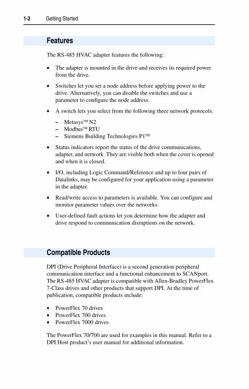
The RS-485 HVAC adapter features the following:
• The adapter is mounted in the drive and receives its required power from the drive.
• Switches let you set a node address before applying power to the drive. Alternatively, you can disable the switches and use a parameter to configure the node address.
• A switch lets you select from the following three network protocols:
– Metasys N2– Modbus RTU– Siemens Building Technologies P1
• Status indicators report the status of the drive communications, adapter, and network. They are visible both when the cover is opened and when it is closed.
• I/O, including Logic Command/Reference and up to four pairs of Datalinks, may be configured for your application using a parameter in the adapter.
• Read/write access to parameters is available. You can configure and monitor parameter values over the networks.
• User-defined fault actions let you determine how the adapter and drive respond to communication disruptions on the network.
DPI (Drive Peripheral Interface) is a second generation peripheral communication interface and a functional enhancement to SCANport. The RS-485 HVAC adapter is compatible with Allen-Bradley PowerFlex 7-Class drives and other products that support DPI. At the time of publication, compatible products include:
• PowerFlex 70 drives• PowerFlex 700 drives• PowerFlex 7000 drives
The PowerFlex 70/700 are used for examples in this manual. Refer to a DPI Host product’s user manual for additional information.
Features
Compatible Products

Getting Started 1-3
Equipment Shipped with the Adapter
When you unpack the adapter, verify that the package includes:
User-Supplied Equipment
To install and configure the RS-485 HVAC adapter, you must supply:
Please read the following safety precautions carefully.
Required Equipment
❑ One RS-485 HVAC adapter❑ A 2.54 cm (1 in.) and a 15.24 cm (6 in.) Internal Interface cable
(only one cable is needed to connect the adapter to the drive)❑ One grounding wrist strap❑ This manual
❑ A small flathead screwdriver❑ Network-specific cable to connect the adapter to the network. Refer
to the network-specific documentation for the cable recommendations and requirements.
❑ Configuration tool, such as:– PowerFlex HIM– DriveExplorer (version 2.01 or higher)– DriveExecutive (version 1.01 or higher)– Third-party network configuration software
Safety Precautions
!ATTENTION: Risk of injury or equipment damage exists. Only qualified electrical personnel familiar with drive and power products and the associated machinery should plan or implement the installation, start up, configuration, and subsequent maintenance of the product using an RS-485 HVAC adapter. Read and understand this manual in its entirety before proceeding. Failure to comply may result in injury and/ or equipment damage.
!ATTENTION: Risk of injury or death exists. The drive may contain high voltages that can cause injury or death. Remove all power from the drive, and then verify power has been removed before installing or removing an RS-485 HVAC adapter.
1-4 Getting Started
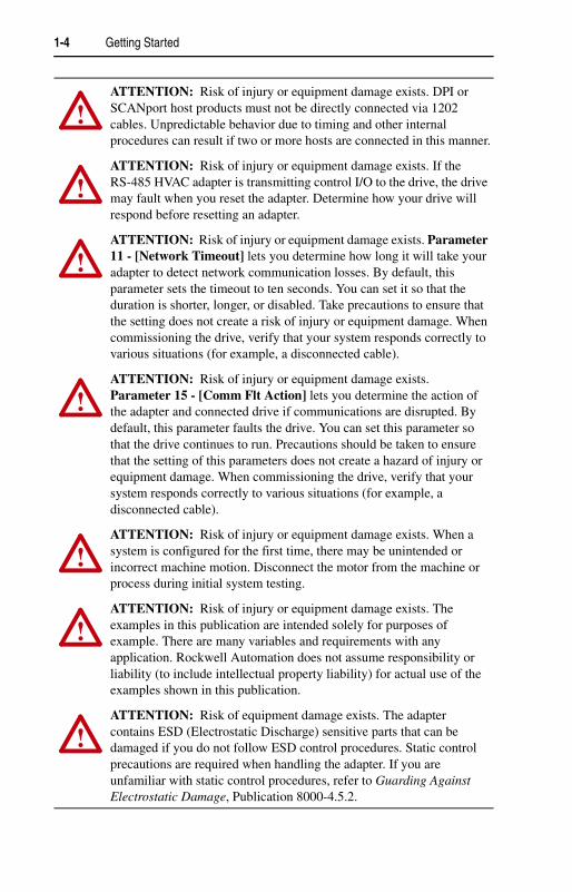
!ATTENTION: Risk of injury or equipment damage exists. DPI or SCANport host products must not be directly connected via 1202 cables. Unpredictable behavior due to timing and other internal procedures can result if two or more hosts are connected in this manner.
!ATTENTION: Risk of injury or equipment damage exists. If the RS-485 HVAC adapter is transmitting control I/O to the drive, the drive may fault when you reset the adapter. Determine how your drive will respond before resetting an adapter.
!ATTENTION: Risk of injury or equipment damage exists. Parameter 11 - [Network Timeout] lets you determine how long it will take your adapter to detect network communication losses. By default, this parameter sets the timeout to ten seconds. You can set it so that the duration is shorter, longer, or disabled. Take precautions to ensure that the setting does not create a risk of injury or equipment damage. When commissioning the drive, verify that your system responds correctly to various situations (for example, a disconnected cable).
!ATTENTION: Risk of injury or equipment damage exists. Parameter 15 - [Comm Flt Action] lets you determine the action of the adapter and connected drive if communications are disrupted. By default, this parameter faults the drive. You can set this parameter so that the drive continues to run. Precautions should be taken to ensure that the setting of this parameters does not create a hazard of injury or equipment damage. When commissioning the drive, verify that your system responds correctly to various situations (for example, a disconnected cable).
!ATTENTION: Risk of injury or equipment damage exists. When a system is configured for the first time, there may be unintended or incorrect machine motion. Disconnect the motor from the machine or process during initial system testing.
!ATTENTION: Risk of injury or equipment damage exists. The examples in this publication are intended solely for purposes of example. There are many variables and requirements with any application. Rockwell Automation does not assume responsibility or liability (to include intellectual property liability) for actual use of the examples shown in this publication.
!ATTENTION: Risk of equipment damage exists. The adapter contains ESD (Electrostatic Discharge) sensitive parts that can be damaged if you do not follow ESD control procedures. Static control precautions are required when handling the adapter. If you are unfamiliar with static control procedures, refer to Guarding Against Electrostatic Damage, Publication 8000-4.5.2.

Getting Started 1-5
This section is designed to help experienced users start using the RS-485 HVAC adapter. If you are unsure how to complete a step, refer to the referenced chapter
Quick Start
Step Action Refer to 1 Review the safety precautions for the adapter. Throughout this
manual2 Verify that the drive is properly installed. Drive User
Manual3 Commission the adapter.
Select the network protocol using the Network Selector switch on the adapter. Set a unique node address using the Node Address switches on the adapter or set both switches to “0” and configure the node address later using a parameter in the adapter.
Chapter 2, Installing the Adapter
4 Install the adapter.Verify that the drive and the network are not powered. Then, connect the adapter to the network and to the drive. Use the captive screws to secure and ground the adapter to the drive.
Chapter 2, Installing the Adapter
5 Apply power to the adapter.Verify that the adapter and network are installed correctly and then apply power to them. The adapter receives power from the drive. The topmost status indicator should be solid green. Refer to Chapter 8, Troubleshooting, for a description of the other LEDs.
Chapter 2, Installing the Adapter
6 Configure the adapter for your application.Set the parameters for the following features as required by your application:• Node address, data rate, and parity• I/O configuration• Fault actions
Chapter 3, Configuring the Adapter
7 Set up the master device to communicate with the adapter.Use a network tool to configure the master device on the network.
Instruction manual for your network tool.
1-6 Getting Started
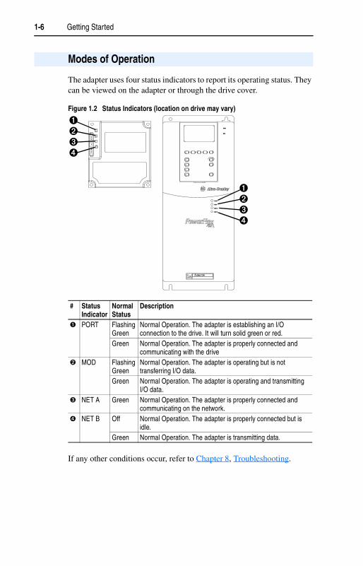
The adapter uses four status indicators to report its operating status. They can be viewed on the adapter or through the drive cover.
Figure 1.2 Status Indicators (location on drive may vary)
If any other conditions occur, refer to Chapter 8, Troubleshooting.
Modes of Operation
# Status Indicator
Normal Status
Description
� PORT Flashing Green
Normal Operation. The adapter is establishing an I/O connection to the drive. It will turn solid green or red.
Green Normal Operation. The adapter is properly connected and communicating with the drive
� MOD Flashing Green
Normal Operation. The adapter is operating but is not transferring I/O data.
Green Normal Operation. The adapter is operating and transmitting I/O data.
� NET A Green Normal Operation. The adapter is properly connected and communicating on the network.
� NET B Off Normal Operation. The adapter is properly connected but is idle.
Green Normal Operation. The adapter is transmitting data.
PWR
STS
PORT
MOD
NET A
NET B
��
��
��
��

Chapter 2
Installing the Adapter
Chapter 2 provides instructions for installing the RS-485 HVAC adapter in a PowerFlex 7-Class drive.
Before installing the adapter, verify that you have all required equipment. Refer to Chapter 1, Getting Started.
To commission the adapter, you must set a unique node address and select a network protocol.
Important: New settings are recognized only when power is applied to the adapter. If you change a switch setting, cycle power to activate the changes.
Topic PagePreparing for the Installation 2-1Commissioning the Adapter 2-1Connecting the Adapter to the Network 2-3Connecting the Adapter to the Drive 2-4Applying Power 2-6
Preparing for the Installation
Commissioning the Adapter
!ATTENTION: Risk of equipment damage exists. The adapter contains ESD (Electrostatic Discharge) sensitive parts that can be damaged if you do not follow ESD control procedures. Static control precautions are required when handling the adapter. If you are unfamiliar with static control procedures, refer to Guarding Against Electrostatic Damage, Publication 8000-4.5.2.
2-2 Installing the Adapter
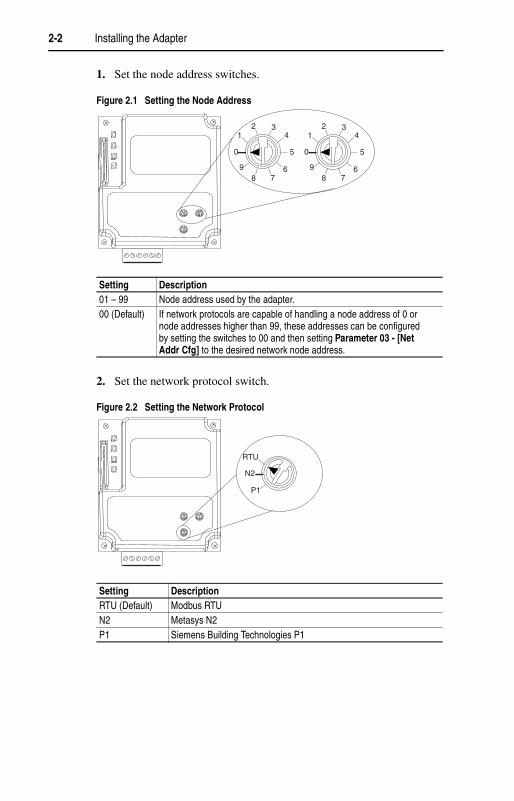
1. Set the node address switches.
Figure 2.1 Setting the Node Address
2. Set the network protocol switch.
Figure 2.2 Setting the Network Protocol
Setting Description01 – 99 Node address used by the adapter. 00 (Default) If network protocols are capable of handling a node address of 0 or
node addresses higher than 99, these addresses can be configured by setting the switches to 00 and then setting Parameter 03 - [Net Addr Cfg] to the desired network node address.
Setting DescriptionRTU (Default) Modbus RTUN2 Metasys N2P1 Siemens Building Technologies P1
21
0
98
34
5
67
21
0
98
34
5
67
RTU
N2
P1
Installing the Adapter 2-3
1. Remove power from the network and drive.
2. Use static control precautions.
3. Open the drive cover.
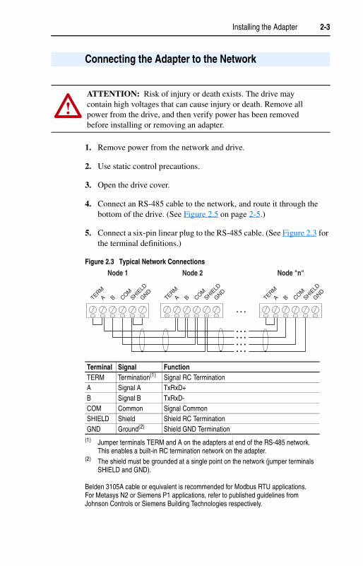
4. Connect an RS-485 cable to the network, and route it through the bottom of the drive. (See Figure 2.5 on page 2-5.)
5. Connect a six-pin linear plug to the RS-485 cable. (See Figure 2.3 for the terminal definitions.)
Figure 2.3 Typical Network Connections
Connecting the Adapter to the Network
!ATTENTION: Risk of injury or death exists. The drive may contain high voltages that can cause injury or death. Remove all power from the drive, and then verify power has been removed before installing or removing an adapter.
Terminal Signal FunctionTERM Termination(1)
(1) Jumper terminals TERM and A on the adapters at end of the RS-485 network. This enables a built-in RC termination network on the adapter.
Signal RC TerminationA Signal A TxRxD+B Signal B TxRxD-COM Common Signal CommonSHIELD Shield Shield RC TerminationGND Ground(2)
(2) The shield must be grounded at a single point on the network (jumper terminals SHIELD and GND).
Belden 3105A cable or equivalent is recommended for Modbus RTU applications. For Metasys N2 or Siemens P1 applications, refer to published guidelines from Johnson Controls or Siemens Building Technologies respectively.
Shield GND Termination
Node 1 Node 2 Node "n"
TERMA B COM
SHIELD
GNDTERM
A B COMSHIE
LD
GNDTERM
A B COMSHIE
LD
GND
2-4 Installing the Adapter
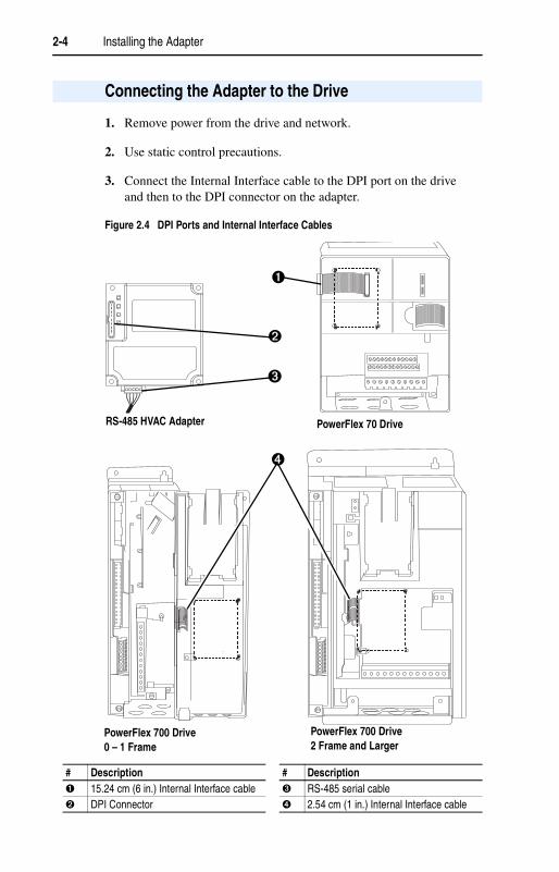
1. Remove power from the drive and network.
2. Use static control precautions.
3. Connect the Internal Interface cable to the DPI port on the drive and then to the DPI connector on the adapter.
Figure 2.4 DPI Ports and Internal Interface Cables
Connecting the Adapter to the Drive
# Description # Description� 15.24 cm (6 in.) Internal Interface cable � RS-485 serial cable� DPI Connector � 2.54 cm (1 in.) Internal Interface cable
�
�
�
�
RS-485 HVAC Adapter
PowerFlex 700 Drive0 – 1 Frame
PowerFlex 700 Drive2 Frame and Larger
PowerFlex 70 Drive

Installing the Adapter 2-5
4. Secure and ground the adapter to the drive by doing the following:
– On a PowerFlex 70, fold the Internal Interface cable behind the adapter and mount the adapter on the drive using the four captive screws.
– On a PowerFlex 700, just mount the adapter on the drive using the four captive screws.
Important: All screws must be tightened since the adapter is grounded through a screw. Recommended torque is 0.9 N-m (8.0 lb.-in.).
Figure 2.5 Mounting and Grounding the Adapter
PowerFlex 70 DriveAdapter mounts in drive.
Internal Interface cable folds behind adapter and in front of the
Drive
Adapter
PowerFlex 700 Drive (0 and 1 Frames)Adapter mounts on door.
PowerFlex 700 Drive (2 & Larger Frames)Adapter mounts in drive.

2-6 Installing the Adapter
1. Close the door or reinstall the cover on the drive. The status indicators can be viewed on the front of the drive after power has been applied.
2. Apply power to the drive. The adapter receives its power from the connected drive. When you apply power to the drive for the first time, the topmost status indicator on the adapter should be solid green. If it is not green, refer to Chapter 8, Troubleshooting.
Applying Power
!ATTENTION: Risk of equipment damage, injury, or death exists. Unpredictable operation may occur if you fail to verify that parameter settings are compatible with your application. Verify that settings are compatible with your application before applying power to the drive.

Chapter 3
Configuring the Adapter
Chapter 3 provides instructions for setting the parameters in the adapter.
For a list of parameters, refer to Appendix B, Adapter Parameters. For definitions of terms in this chapter, refer to the Glossary.
The RS-485 HVAC adapter stores parameters and other information in its own non-volatile memory. You must, therefore, access the adapter to view and edit its parameters. The following tools can be used to access the adapter parameters:
Topic Page Topic PageConfiguration Tools 3-1 Setting the I/O Configuration 3-4Using the PowerFlex HIM 3-2 Setting a Network Time-out 3-5Setting the Node Address 3-3 Setting a Fault Action 3-6Setting the Network Data Rate 3-3 Resetting the Adapter 3-8Setting the Network Parity 3-4 Viewing the Adapter Configuration 3-8
Configuration Tools
Tool Refer To:PowerFlex HIM page 3-2DriveExecutive Software (version 1.01 or higher)
DriveExecutive online help
DriveExplorer Software (version 2.01 or higher)
DriveExplorer Getting Results Manual, Publication 9306-GR001... (Download Only), or the online help
3-2 Configuring the Adapter
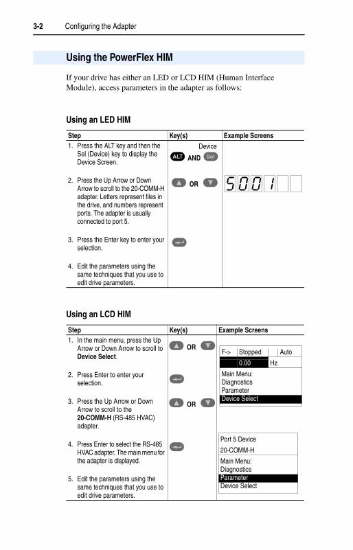
If your drive has either an LED or LCD HIM (Human Interface Module), access parameters in the adapter as follows:
Using an LED HIM
Using an LCD HIM
Using the PowerFlex HIM
Step Key(s) Example Screens1. Press the ALT key and then the
Sel (Device) key to display the Device Screen.
2. Press the Up Arrow or Down Arrow to scroll to the 20-COMM-H adapter. Letters represent files in the drive, and numbers represent ports. The adapter is usually connected to port 5.
3. Press the Enter key to enter your selection.
4. Edit the parameters using the same techniques that you use to edit drive parameters.
Step Key(s) Example Screens1. In the main menu, press the Up
Arrow or Down Arrow to scroll to Device Select.
2. Press Enter to enter your selection.
3. Press the Up Arrow or Down Arrow to scroll to the 20-COMM-H (RS-485 HVAC) adapter.
4. Press Enter to select the RS-485 HVAC adapter. The main menu for the adapter is displayed.
5. Edit the parameters using the same techniques that you use to edit drive parameters.
ALT Sel
OR
Device
AND
OR
OR
F-> Stopped Auto
0.00 Hz
Main Menu:DiagnosticsParameterDevice Select
Port 5 Device
20-COMM-H
Main Menu:DiagnosticsParameterDevice Select

Configuring the Adapter 3-3
If the Node Address switches are set to 00, then the value in Parameter 03 - [Net Addr Cfg] is used to configure the node address.
1. Set the value of Parameter 03 - [Net Addr Cfg] to a unique node address.
Figure 3.1 Node Address Screen on an LCD HIM
2. Reset the adapter. Refer to the Resetting the Adapter section in this chapter. The actual node address is then displayed in Parameter 04 - [Net Addr Act].
The data rate at which the adapter operates varies based on the type of network and your network configuration. Refer to the following table.
1. Set the value of Parameter 05 - [Net Rate Cfg] to the data rate at which your network is operating.
Figure 3.2 Data Rate Screen on an LCD HIM
2. Reset the adapter. Refer to the Resetting the Adapter section in this chapter. The actual data rate is then displayed in Parameter 06 - [Net Rate Act].
Setting the Node Address
Port 5 Device
20-COMM-H
Parameter #: 03Net Addr Cfg
10 <> 247
Default = 1
Setting the Network Data Rate
Network Possible Data RatesModbus RTU 4800, 9600, 19200, 38400Metasys N2 9600Siemens Building Technologies P1 4800, 9600
Value Baud0 48001 9600 (Default)2 192003 38400
Port 5 Device
20-COMM-H
Parameter #: 05Net Rate Cfg
19600

3-4 Configuring the Adapter
The parity that the adapter uses to verify data integrity varies based on the type of network and your network configuration. Refer to the following table.
1. Set the value of Parameter 07 - [Net Parity Cfg] to the type of parity that is used on the network.
Figure 3.3 Network Parity Screen on an LCD HIM
2. Reset the adapter. Refer to the Resetting the Adapter section in this chapter. The actual network parity is then displayed in Parameter 08 - [Net Parity Act].
The I/O configuration determines the type of data sent to the drive. Logic Command/Status and Datalinks may be enabled or disabled.
1. Set the bits in Parameter 16 - [DPI I/O Cfg]. A “1” enables the I/O. A “0” disables it.
Figure 3.4 DPI I/O Configuration Screen
Bit 0 is the right-most bit. In Figure 3.4, it is highlighted and equals “1.”
Setting the Network Parity
Network Possible Types of ParityModbus RTU None, Even, or OddMetasys N2 NoneSiemens Building Technologies P1 None
Value Type of Parity0 None (Default)1 Odd2 Even
Port 5 Device
20-COMM-H
Parameter #: 07Net Parity Cfg
0None
Setting the I/O Configuration
Bit Description0 Logic Command/Reference (Default)1 Datalink A2 Datalink B3 Datalink C (not used with Metasys N2)4 Datalink D (not used with Metasys N2)5 - 15 Not Used
Port 5 Device
20-COMM-H
Parameter #: 16DPI I/O Cfgx x x x x x x x x x x 0 0 0 0 1Cmd/Ref b00
Configuring the Adapter 3-5
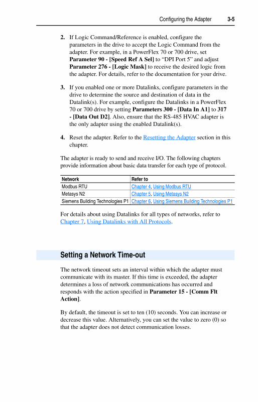
2. If Logic Command/Reference is enabled, configure the parameters in the drive to accept the Logic Command from the adapter. For example, in a PowerFlex 70 or 700 drive, set Parameter 90 - [Speed Ref A Sel] to “DPI Port 5” and adjust Parameter 276 - [Logic Mask] to receive the desired logic from the adapter. For details, refer to the documentation for your drive.
3. If you enabled one or more Datalinks, configure parameters in the drive to determine the source and destination of data in the Datalink(s). For example, configure the Datalinks in a PowerFlex 70 or 700 drive by setting Parameters 300 - [Data In A1] to 317 - [Data Out D2]. Also, ensure that the RS-485 HVAC adapter is the only adapter using the enabled Datalink(s).
4. Reset the adapter. Refer to the Resetting the Adapter section in this chapter.
The adapter is ready to send and receive I/O. The following chapters provide information about basic data transfer for each type of protocol.
For details about using Datalinks for all types of networks, refer to Chapter 7, Using Datalinks with All Protocols.
The network timeout sets an interval within which the adapter must communicate with its master. If this time is exceeded, the adapter determines a loss of network communications has occurred and responds with the action specified in Parameter 15 - [Comm Flt Action].
By default, the timeout is set to ten (10) seconds. You can increase or decrease this value. Alternatively, you can set the value to zero (0) so that the adapter does not detect communication losses.
Network Refer to Modbus RTU Chapter 4, Using Modbus RTUMetasys N2 Chapter 5, Using Metasys N2Siemens Building Technologies P1 Chapter 6, Using Siemens Building Technologies P1
Setting a Network Time-out

3-6 Configuring the Adapter
• Set the network timeout in Parameter 11 - [Network Timeout].
Figure 3.5 Network Timeout Screen on an LCD HIM
Changes to this parameter take effect immediately. A reset is not required.
By default, when communications are disrupted (for example, a cable is disconnected), the drive responds by faulting if it is using I/O from the network. You can configure a different response to communication disruptions using Parameter 15 - [Comm Flt Action].
!ATTENTION: Risk of injury or equipment damage exists. Parameter 11 - [Network Timeout] lets you determine how long it will take your adapter to detect network communication losses. By default, this parameter sets the timeout to ten (10) seconds. You can set it so that the duration is shorter, longer, or disabled. Take precautions to ensure that the setting does not create a risk of injury or equipment damage. When commissioning the drive, verify that your system responds correctly to various situations (for example, a disconnected cable).
Port 5 Device
20-COMM-H
Parameter #: 11Network Timeout
10 Sec0 <> 180
Default = 10 Seconds
Setting a Fault Action
!ATTENTION: Risk of injury or equipment damage exists. Parameter 15 - [Comm Flt Action] lets you determine the action of the adapter and connected drive if communications are disrupted. By default, this parameter faults the drive. You can set this parameter so that the drive continues to run. Precautions should be taken to ensure that the setting of this parameter does not create a risk of injury or equipment damage. When commissioning the drive, verify that your system responds correctly to various situations (for example, a disconnected cable).
Configuring the Adapter 3-7
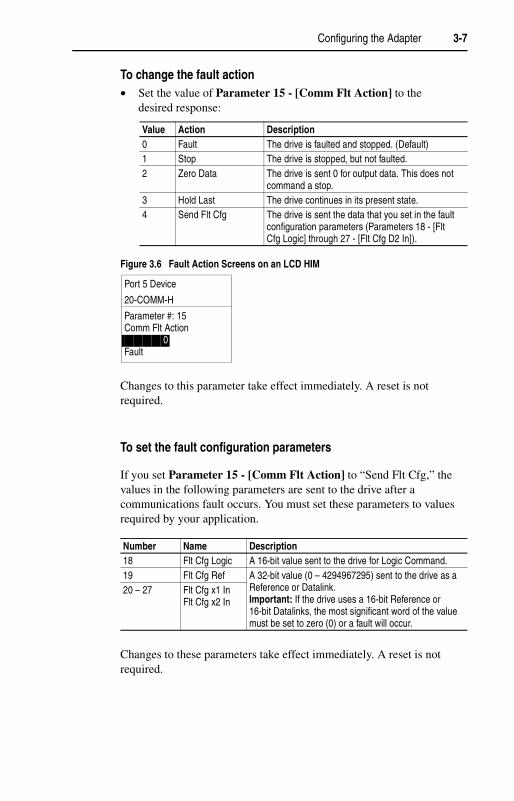
To change the fault action • Set the value of Parameter 15 - [Comm Flt Action] to the
desired response:
Figure 3.6 Fault Action Screens on an LCD HIM
Changes to this parameter take effect immediately. A reset is not required.
To set the fault configuration parameters
If you set Parameter 15 - [Comm Flt Action] to “Send Flt Cfg,” the values in the following parameters are sent to the drive after a communications fault occurs. You must set these parameters to values required by your application.
Changes to these parameters take effect immediately. A reset is not required.
Value Action Description0 Fault The drive is faulted and stopped. (Default)1 Stop The drive is stopped, but not faulted.2 Zero Data The drive is sent 0 for output data. This does not
command a stop.3 Hold Last The drive continues in its present state.4 Send Flt Cfg The drive is sent the data that you set in the fault
configuration parameters (Parameters 18 - [Flt Cfg Logic] through 27 - [Flt Cfg D2 In]).
Number Name Description18 Flt Cfg Logic A 16-bit value sent to the drive for Logic Command. 19 Flt Cfg Ref A 32-bit value (0 – 4294967295) sent to the drive as a
Reference or Datalink. Important: If the drive uses a 16-bit Reference or 16-bit Datalinks, the most significant word of the value must be set to zero (0) or a fault will occur.
20 – 27 Flt Cfg x1 InFlt Cfg x2 In
Port 5 Device
20-COMM-H
Parameter #: 15Comm Flt Action
0Fault
3-8 Configuring the Adapter
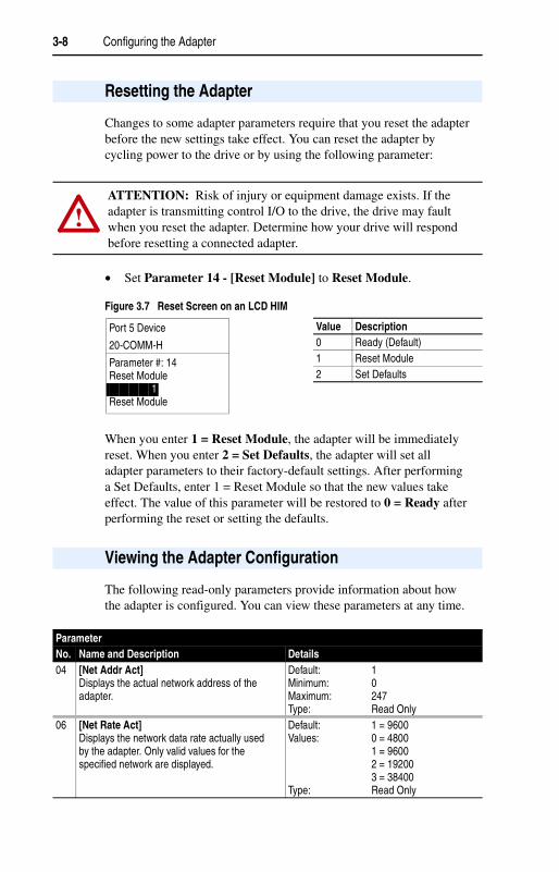
Changes to some adapter parameters require that you reset the adapter before the new settings take effect. You can reset the adapter by cycling power to the drive or by using the following parameter:
• Set Parameter 14 - [Reset Module] to Reset Module.
Figure 3.7 Reset Screen on an LCD HIM
When you enter 1 = Reset Module, the adapter will be immediately reset. When you enter 2 = Set Defaults, the adapter will set all adapter parameters to their factory-default settings. After performing a Set Defaults, enter 1 = Reset Module so that the new values take effect. The value of this parameter will be restored to 0 = Ready after performing the reset or setting the defaults.
The following read-only parameters provide information about how the adapter is configured. You can view these parameters at any time.
Resetting the Adapter
!ATTENTION: Risk of injury or equipment damage exists. If the adapter is transmitting control I/O to the drive, the drive may fault when you reset the adapter. Determine how your drive will respond before resetting a connected adapter.
Value Description0 Ready (Default)1 Reset Module2 Set Defaults
Port 5 Device
20-COMM-H
Parameter #: 14Reset Module
1Reset Module
Viewing the Adapter Configuration
Parameter No. Name and Description Details04 [Net Addr Act]
Displays the actual network address of the adapter.
Default: 1Minimum: 0Maximum: 247Type: Read Only
06 [Net Rate Act]Displays the network data rate actually used by the adapter. Only valid values for the specified network are displayed.
Default: 1 = 9600Values: 0 = 4800
1 = 96002 = 192003 = 38400
Type: Read Only
Configuring the Adapter 3-9
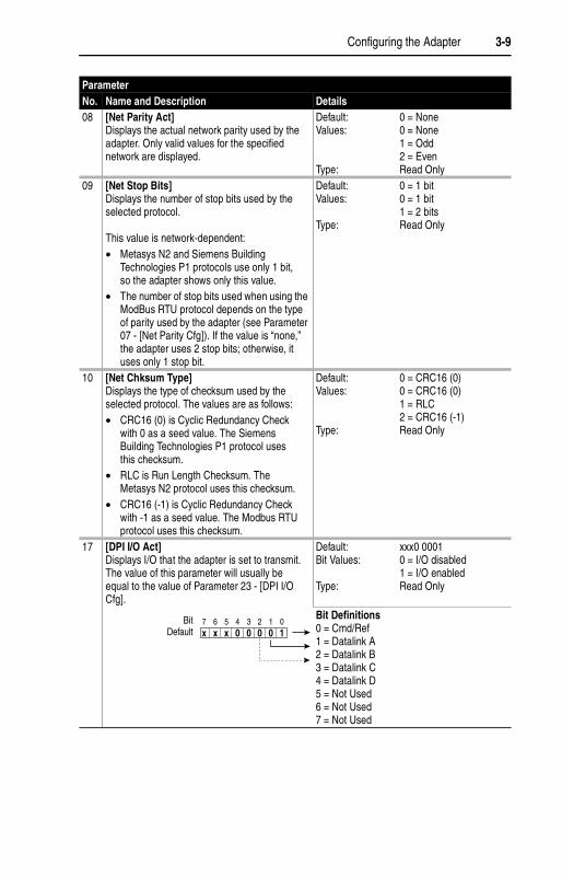
08 [Net Parity Act]Displays the actual network parity used by the adapter. Only valid values for the specified network are displayed.
Default: 0 = NoneValues: 0 = None
1 = Odd2 = Even
Type: Read Only09 [Net Stop Bits]
Displays the number of stop bits used by the selected protocol.
This value is network-dependent:• Metasys N2 and Siemens Building
Technologies P1 protocols use only 1 bit, so the adapter shows only this value.
• The number of stop bits used when using the ModBus RTU protocol depends on the type of parity used by the adapter (see Parameter 07 - [Net Parity Cfg]). If the value is “none,” the adapter uses 2 stop bits; otherwise, it uses only 1 stop bit.
Default: 0 = 1 bitValues: 0 = 1 bit
1 = 2 bitsType: Read Only
10 [Net Chksum Type]Displays the type of checksum used by the selected protocol. The values are as follows:• CRC16 (0) is Cyclic Redundancy Check
with 0 as a seed value. The Siemens Building Technologies P1 protocol uses this checksum.
• RLC is Run Length Checksum. The Metasys N2 protocol uses this checksum.
• CRC16 (-1) is Cyclic Redundancy Check with -1 as a seed value. The Modbus RTU protocol uses this checksum.
Default: 0 = CRC16 (0)Values: 0 = CRC16 (0)
1 = RLC2 = CRC16 (-1)
Type: Read Only
17 [DPI I/O Act]Displays I/O that the adapter is set to transmit. The value of this parameter will usually be equal to the value of Parameter 23 - [DPI I/O Cfg].
Default: xxx0 0001Bit Values: 0 = I/O disabled
1 = I/O enabledType: Read Only
Bit Definitions0 = Cmd/Ref1 = Datalink A2 = Datalink B3 = Datalink C4 = Datalink D5 = Not Used6 = Not Used7 = Not Used
Parameter No. Name and Description Details
BitDefault 10000x xx
0123457 6

3-10 Configuring the Adapter
Notes:

Chapter 4
Using Modbus RTU
Chapter 4 provides information about controlling a PowerFlex 7-Class drive, setting its Reference, and accessing its parameters through configurable objects when the Modbus RTU network protocol is selected.
The Modbus RTU protocol is a messaging structure used to establish master-slave communication between intelligent devices. The protocol defines the format of the messages.
Messages from a master to a slave contain the address of the slave, a function code defining the requested action, any data to be sent, and an error-checking field. Messages from a slave to a master contain fields confirming the action taken, any data to be returned, and an error-checking field. If an error occurred in the receipt of the message or if the slave is unable to perform the requested action, the slave will construct an error message and send it as its response.
Modbus RTU can access a single address or multiple addresses simultaneously, either reading or writing single-bit values or 16-bit values.
Topic PageUnderstanding Modbus RTU 4-1Using the Modbus RTU Point Map for I/O 4-3Using Modbus Configurable Objects to Access Parameters
4-8
TIP: Datalinks can also be used for accessing parameters. For information about using Datalinks, refer to Chapter 7, Using Datalinks with All Protocols.
Understanding Modbus RTU
4-2 Using Modbus RTU
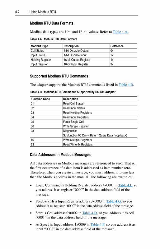
Modbus RTU Data Formats
Modbus data types are 1-bit and 16-bit values. Refer to Table 4.A.
Supported Modbus RTU Commands
The adapter supports the Modbus RTU commands listed in Table 4.B.
Data Addresses in Modbus Messages
All data addresses in Modbus messages are referenced to zero. That is, the first occurrence of a data item is addressed as item number zero. Therefore, when you create a message, you must address it to one less than the Modbus address in the manual. The following are examples:
• Logic Command is Holding Register address 4x0001 in Table 4.E, so you address it as register “0000” in the data address field of the message.
• Feedback Hi is Input Register address 3x0003 in Table 4.G, so you address it as register “0002” in the data address field of the message.
• Start is Coil address 0x0002 in Table 4.D, so you address it as coil “0001” in the data address field of the message.
• At Speed is Input address 1x0009 in Table 4.F, so you address it as input “0008” in the data address field of the message.
Table 4.A Mobus RTU Data Formats
Modbus Type Description ReferenceCoil Status 1-bit Discrete Output 0xInput Status 1-bit Discrete Input 1xHolding Register 16-bit Output Register 4xInput Register 16-bit Input Register 3x
Table 4.B Modbus RTU Commands Supported by RS-485 Adapter
Function Code Description01 Read Coil Status02 Read Input Status03 Read Holding Registers04 Read Input Registers05 Force Single Coil06 Write Single Register08 Diagnostics
Subfunction 00 Only - Return Query Data (loop back)16 Write Multiple Registers23 Read/Write 4x Registers
Using Modbus RTU 4-3
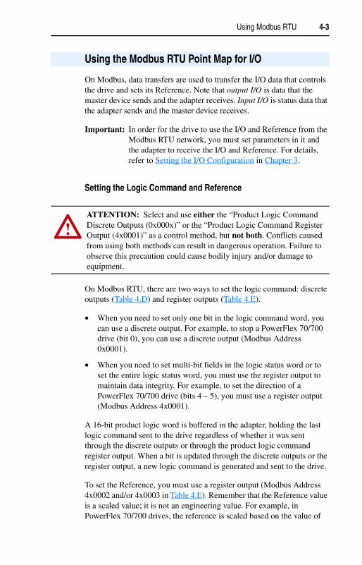
On Modbus, data transfers are used to transfer the I/O data that controls the drive and sets its Reference. Note that output I/O is data that the master device sends and the adapter receives. Input I/O is status data that the adapter sends and the master device receives.
Important: In order for the drive to use the I/O and Reference from the Modbus RTU network, you must set parameters in it and the adapter to receive the I/O and Reference. For details, refer to Setting the I/O Configuration in Chapter 3.
Setting the Logic Command and Reference
On Modbus RTU, there are two ways to set the logic command: discrete outputs (Table 4.D) and register outputs (Table 4.E).
• When you need to set only one bit in the logic command word, you can use a discrete output. For example, to stop a PowerFlex 70/700 drive (bit 0), you can use a discrete output (Modbus Address 0x0001).
• When you need to set multi-bit fields in the logic status word or to set the entire logic status word, you must use the register output to maintain data integrity. For example, to set the direction of a PowerFlex 70/700 drive (bits 4 – 5), you must use a register output (Modbus Address 4x0001).
A 16-bit product logic word is buffered in the adapter, holding the last logic command sent to the drive regardless of whether it was sent through the discrete outputs or through the product logic command register output. When a bit is updated through the discrete outputs or the register output, a new logic command is generated and sent to the drive.
To set the Reference, you must use a register output (Modbus Address 4x0002 and/or 4x0003 in Table 4.E). Remember that the Reference value is a scaled value; it is not an engineering value. For example, in PowerFlex 70/700 drives, the reference is scaled based on the value of
Using the Modbus RTU Point Map for I/O
!ATTENTION: Select and use either the “Product Logic Command Discrete Outputs (0x000x)” or the “Product Logic Command Register Output (4x0001)” as a control method, but not both. Conflicts caused from using both methods can result in dangerous operation. Failure to observe this precaution could cause bodily injury and/or damage to equipment.
4-4 Using Modbus RTU
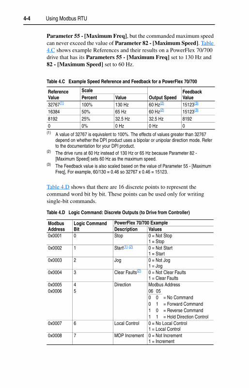
Parameter 55 - [Maximum Freq], but the commanded maximum speed can never exceed the value of Parameter 82 - [Maximum Speed]. Table 4.C shows example References and their results on a PowerFlex 70/700 drive that has its Parameters 55 - [Maximum Freq] set to 130 Hz and 82 - [Maximum Speed] set to 60 Hz.
Table 4.D shows that there are 16 discrete points to represent the command word bit by bit. These points can be used only for writing single-bit commands.
Table 4.C Example Speed Reference and Feedback for a PowerFlex 70/700
Reference Value
ScaleOutput Speed
Feedback ValuePercent Value
32767(1)
(1) A value of 32767 is equivalent to 100%. The effects of values greater than 32767 depend on whether the DPI product uses a bipolar or unipolar direction mode. Refer to the documentation for your DPI product.
100% 130 Hz 60 Hz(2)
(2) The drive runs at 60 Hz instead of 130 Hz or 65 Hz because Parameter 82 - [Maximum Speed] sets 60 Hz as the maximum speed.
15123(3)
(3) The Feedback value is also scaled based on the value of Parameter 55 - [Maximum Freq], For example, 60/130 = 0.46 so 32767 x 0.46 = 15123.
16384 50% 65 Hz 60 Hz(2) 15123(3)
8192 25% 32.5 Hz 32.5 Hz 81920 0% 0 Hz 0 Hz 0
Table 4.D Logic Command: Discrete Outputs (to Drive from Controller)
Modbus Address
Logic Command Bit
PowerFlex 70/700 ExampleDescription Values
0x0001 0 Stop 0 = Not Stop1 = Stop
0x0002 1 Start(1) (2) 0 = Not Start1 = Start
0x0003 2 Jog 0 = Not Jog1 = Jog
0x0004 3 Clear Faults(2) 0 = Not Clear Faults1 = Clear Faults
0x0005 4 Direction Modbus Address0x0006 5 06 05
0 0 = No Command0 1 = Forward Command1 0 = Reverse Command1 1 = Hold Direction Control
0x0007 6 Local Control 0 = No Local Control1 = Local Control
0x0008 7 MOP Increment 0 = Not Increment1 = Increment
Using Modbus RTU 4-5
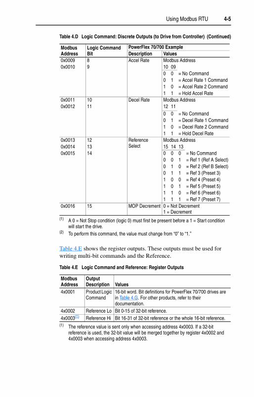
Table 4.E shows the register outputs. These outputs must be used for writing multi-bit commands and the Reference.
0x0009 8 Accel Rate Modbus Address0x0010 9 10 09
0 0 = No Command0 1 = Accel Rate 1 Command1 0 = Accel Rate 2 Command1 1 = Hold Accel Rate
0x0011 10 Decel Rate Modbus Address0x0012 11 12 11
0 0 = No Command0 1 = Decel Rate 1 Command1 0 = Decel Rate 2 Command1 1 = Hold Decel Rate
0x0013 12 Reference Select
Modbus Address0x0014 13 15 14 130x0015 14 0 0 0 = No Command
0 0 1 = Ref 1 (Ref A Select)0 1 0 = Ref 2 (Ref B Select)0 1 1 = Ref 3 (Preset 3)1 0 0 = Ref 4 (Preset 4)1 0 1 = Ref 5 (Preset 5)1 1 0 = Ref 6 (Preset 6)1 1 1 = Ref 7 (Preset 7)
0x0016 15 MOP Decrement 0 = Not Decrement1 = Decrement
(1) A 0 = Not Stop condition (logic 0) must first be present before a 1 = Start condition will start the drive.
(2) To perform this command, the value must change from “0” to “1.”
Table 4.E Logic Command and Reference: Register Outputs
Modbus Address
Output Description Values
4x0001 Product Logic Command
16-bit word. Bit definitions for PowerFlex 70/700 drives are in Table 4.G. For other products, refer to their documentation.
4x0002 Reference Lo Bit 0-15 of 32-bit reference.4x0003(1)
(1) The reference value is sent only when accessing address 4x0003. If a 32-bit reference is used, the 32-bit value will be merged together by register 4x0002 and 4x0003 when accessing address 4x0003.
Reference Hi Bit 16-31 of 32-bit reference or the whole 16-bit reference.
Table 4.D Logic Command: Discrete Outputs (to Drive from Controller) (Continued)
Modbus Address
Logic Command Bit
PowerFlex 70/700 ExampleDescription Values

4-6 Using Modbus RTU
Viewing the Logic Status and Feedback
On Modbus RTU, there are two ways to view the logic status: discrete inputs (Table 4.F) and register inputs (Table 4.G). You can use discrete inputs when you need to view only one bit in the logic status word. For example, to view whether a PowerFlex 70/700 drive is Ready (bit 0), you can use a discrete input (Modbus Address 1x0001).
When you need to view multi-bit fields in the logic status word or to view the entire logic status word, you must use a register input to maintain data integrity. For example, to view the local control of a PowerFlex 70/700 drive (bits 9 – 11), you must use a register input (Modbus Address 3x0001).
To view the Feedback, you must also use a register input (Modbus Address 3x0002 and/or 3x0003). For details about how the feedback is scaled, refer to the Setting the Logic Command and Reference section in this chapter.
Table 4.F shows that there are 16 discrete points to represent the status word bit by bit. These points can be used only for reading single-bit status.
Table 4.F Logic Status: Discrete Inputs (to Controller from Drive)
Modbus Address
Logic Status Bit
PowerFlex 70/700 ExampleDescription Values
1x0001 0 Ready 0 = Not Ready1 = Ready
1x0002 1 Active 0 = Not Running1 = Running
1x0003 2 Command Direction 0 = Reverse1 = Forward
1x0004 3 Actual Direction 0 = Reverse1 = Forward
1x0005 4 Accel 0 = Not Accelerating1 = Accelerating
1x0006 5 Decel 0 = Not Decelerating1 = Decelerating
1x0007 6 Alarm 0 = No Alarm1 = Alarm
1x0008 7 Fault 0 = No Fault1 = Fault
1x0009 8 At Speed 0 = Not At Reference1 = At Reference

Using Modbus RTU 4-7
Table 4.G shows the register inputs. These inputs must be used for reading multi-bit status fields and the Feedback.
1x0010 9 Local Control Modbus Address1x0011 10 12 11 101x0012 11 0 0 0 = Port 0 (TB)
0 0 1 = Port 10 1 0 = Port 20 1 1 = Port 31 0 0 = Port 41 0 1 = Port 51 1 0 = Port 61 1 1 = No Local
1x0013 12 Reference Modbus Address1x0014 13 16 15 14 131x0015 14 0 0 0 0 = Ref A Auto1x0016 15 0 0 0 1 = Ref B Auto
0 0 1 0 = Preset 2 Auto0 0 1 1 = Preset 3 Auto0 1 0 0 = Preset 4 Auto0 1 0 1 = Preset 5 Auto0 1 1 0 = Preset 6 Auto0 1 1 1 = Preset 7 Auto1 0 0 0 = Term Blk Manual1 0 0 1 = DPI 1 Manual1 0 1 0 = DPI 2 Manual1 0 1 1 = DPI 3 Manual1 1 0 0 = DPI 4 Manual1 1 0 1 = DPI 5 Manual1 1 1 0 = DPI 6 manual1 1 1 1 = Jog Ref
Table 4.G Logic Status and Feedback: Register Inputs
Modbus Address
Input Description Values
3x0001 Product Status Word
16-bit word. Bit definitions for PowerFlex 70/700 drives are in Table 4.F. For other products, refer to their documentation.
3x0002 Feedback Lo Bit 0-15 of 32-bit feedback3x0003(1)
(1) The Feedback value is refreshed only when accessing address 3x0003. This is to maintain data integrity.
Feedback Hi Bit 16-31 of 32-bit feedback or the whole 16-bit feedback.
Table 4.F Logic Status: Discrete Inputs (to Controller from Drive) (Continued)
Modbus Address
Logic Status Bit
PowerFlex 70/700 ExampleDescription Values
4-8 Using Modbus RTU
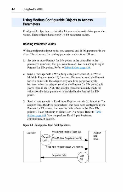
Configurable objects are points that let you read or write drive parameter values. These objects handle only 16-bit parameter values.
Reading Parameter Values
With a configurable input point, you can read any 16-bit parameter in the drive. The sequence for reading parameter values is as follows:
1. Set one or more Param# for INx points in the controller to the parameter number(s) that you want to read. You can set up to eight Param# for INx points. Refer to Table 4.H on page 4-9.
2. Send a message with a Write Single Register (code 06) or Write Multiple Register (code 16) function. You need to send the Param# for INx point(s) to the adapter only one time per power cycle because, when the adapter receives the Param# for INx point(s), it stores them in its RAM. The adapter then continuously reads the values for the drive parameters specified in the Param# for INx points.
3. Send a message with a Read Input Registers (code 04) function. The adapter reads the drive parameter(s) that have been configured in the Param# for IN point(s) and returns their values in the User INx point(s). It can return up to eight User INx points. Refer to Table 4.H on page 4-9. You can perform Read Input Registers continuously, if desired.
Figure 4.1 Configurable Input Point Operations
Using Modbus Configurable Objects to Access Parameters
Controller Adapter and Drive
Param# for INx
User INx
Write Single Register (code 06)orWrite Multiple Register (code 16)
Read Input Registers (code 04) Request
Response Data

Using Modbus RTU 4-9
Writing Parameter Values
With a configurable output point, you can write a new value for any 16-bit parameter in the drive. The sequence for writing parameter values is as follows:
1. Set one or more Param# for OUTx points in the controller to the parameter number(s) to which you want to write. A value of zero in the Param# field disables the writing of data for that specific point. Refer to the drive user manual for the desired parameter number(s). You can set up to three Param# for OUTx points at a time. Refer to Table 4.I on page 4-10.
2. Send a message with a Write Single Register (code 06) or Write Multiple Register (code 16) function. You need to send the Param# for OUTx point(s) to the adapter only one time per power cycle because, when the adapter receives the Param# for OUTx point(s), it stores them in its RAM.
Table 4.H Configurable Objects Inputs
Modbus Address Data Direction
Parameter Description Values
User Default
3x0004 Register Input User IN1 User-defined Input 1 03x0005 Register Input User IN2 User-defined Input 2 03x0006 Register Input User IN3 User-defined Input 3 03x0007 Register Input User IN4 User-defined Input 4 03x0008 Register Input User IN5 User-defined Input 5 03x0009 Register Input User IN6 User-defined Input 6 03x0010 Register Input User IN7 User-defined Input 7 03x0011 Register Input User IN8 User-defined Input 8 0
4x0004 Register Output Param# for IN1 0 = Not in use 04x0005 Register Output Param# for IN2 0 = Not in use 04x0006 Register Output Param# for IN3 0 = Not in use 04x0007 Register Output Param# for IN4 0 = Not in use 04x0008 Register Output Param# for IN5 0 = Not in use 04x0009 Register Output Param# for IN6 0 = Not in use 04x0010 Register Output Param# for IN7 0 = Not in use 04x0011 Register Output Param# for IN8 0 = Not in use 0
!ATTENTION: Risk of equipment damage exists. If configurable output points are programmed to write parameter data to Non-Volatile Storage (NVS) frequently, the NVS will quickly exceed its life cycle and cause the drive to malfunction. Do not create a program that frequently uses configurable outputs to write parameter data to NVS. Datalinks do not write to NVS and should be used for frequently changed parameters.

4-10 Using Modbus RTU
3. Set the values that you want to write to the parameters in the User OUTx points. You can set up to three User OUTx points at a time. Refer to Table 4.I on page 4-10.
4. Send a message with a Write Single Register (code 06) or Write Multiple Register (code 16) function. Each time that the adapter receives the values in the User OUTx points, it writes them to the drive parameters.
Figure 4.2 Configurable Output Point Operations
Table 4.I Configurable Objects: Outputs
Modbus Address Data Direction
Parameter Description Values
User Default
4x0012 Register Output User OUT1 User-defined Output 1 04x0013 Register Output User OUT2 User-defined Output 2 04x0014 Register Output User OUT3 User-defined Output 3 04x0015 Register Output Param# for OUT1 0 = Not in use 04x0016 Register Output Param# for OUT2 0 = Not in use 04x0017 Register Output Param# for OUT3 0 = Not in use 0
Controller Adapter and DriveParam#
for OUTx
User OUTx
Write Single Register (code 06)orWrite Multiple Register (code 16)
Write Single Register (code 06)orWrite Multiple Register (code 16)
Chapter 5
Using Metasys N2
Chapter 5 provides information about controlling a PowerFlex 7-Class drive, setting its Reference, and accessing its parameters through configurable objects when the Metasys N2 network protocol is selected.
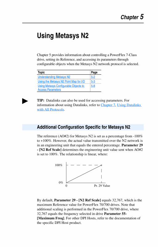
The reference (AO#2) for Metasys N2 is set as a percentage from -100% to +100%. However, the actual value transmitted over the N2 network is in an engineering unit that equals the entered percentage. Parameter 29 - [N2 Ref Scale] determines the engineering unit value sent when AO#2 is set to 100%. The relationship is linear, where:
By default, Parameter 29 - [N2 Ref Scale] equals 32,767, which is the maximum Reference value for PowerFlex 70/700 drives. Note that additional scaling is performed in the PowerFlex 70/700 drive, where 32,767 equals the frequency selected in drive Parameter 55- [Maximum Freq]. For other DPI Hosts, refer to the documentation of the specific DPI Host product.
Topic PageUnderstanding Metasys N2 5-2Using the Metasys N2 Point Map for I/O 5-3Using Metasys Configurable Objects to Access Parameters
5-8
TIP: Datalinks can also be used for accessing parameters. For information about using Datalinks, refer to Chapter 7, Using Datalinks with All Protocols.
Additional Configuration Specific for Metasys N2
100%
0%0 Pr. 29 Value
5-2 Using Metasys N2
Metasys nodes are built up by the use of several virtual objects. The Metasys N2 master performs read and write commands to these virtual objects, and the adapter transfers/translates the data between these virtual objects and the drive.
When a read or write command occurs to a certain dedicated virtual object, data in the virtual objects is refreshed from or transferred to the drive.
The Metasys N2 master performs read and write commands to the virtual objects one at a time. The data types that are used in the virtual objects are binary input (BI), binary output (BO), analog input (AI), analog output (AO), and internal integer (ADI), which is a 16-bit data value.
The Metasys master also performs cyclic polling of all the virtual objects.
Metasys N2 Virtual Objects
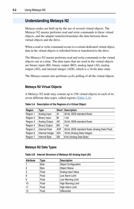
A Metasys N2 node may contain up to 256 virtual objects in each of its seven different data types, called regions (Table 5.A).
Metasys N2 Data Types
Understanding Metasys N2
Table 5.A Description of the Regions of a Virtual Object
Region Type Short DescriptionRegion 1 Analog Input AI 32-bit, IEEE-standard floatsRegion 2 Binary Input BI 1-bitRegion 3 Analog Output AO 32-bit, IEEE-standard floatsRegion 4 Binary Output BO 1-bitRegion 5 Internal Float ADF 32-bit, IEEE-standard floats (Analog Data Float)Region 6 Internal Integer ADI 16-bit (Analog Data Integer)Region 7 Internal Byte DB 8-bit (Analog Data Byte)
Table 5.B Internal Structure of Metasys N2 Analog Input (AI)
Attribute Type Description1 Byte Object Configuration2 Byte Object Status3 Float Analog Input Value8 Float Low Alarm Limit9 Float Low Warning Limit10 Float High Warning Limit11 Float High Alarm Limit12 Float Differential
Using Metasys N2 5-3
On Metasys N2, data transfers are used to transfer the I/O data that controls the drive and sets its Reference. Note that Output I/O is data that the master device sends and the adapter receives. Input I/O is status data that the adapter sends and the master device receives.
Important: In order for the drive to use the I/O and Reference from the Metasys N2 network, you must set parameters in it and the adapter to receive the I/O and Reference. For details, refer to Setting the I/O Configuration in Chapter 3.
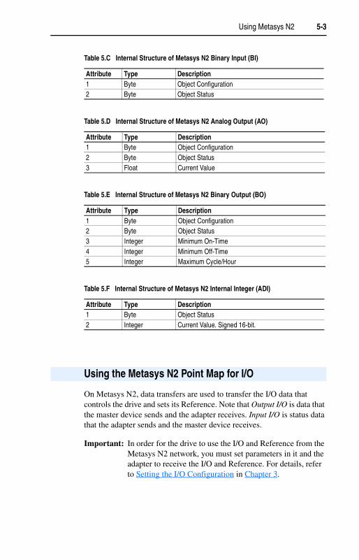
Table 5.C Internal Structure of Metasys N2 Binary Input (BI)
Attribute Type Description1 Byte Object Configuration2 Byte Object Status
Table 5.D Internal Structure of Metasys N2 Analog Output (AO)
Attribute Type Description1 Byte Object Configuration2 Byte Object Status3 Float Current Value
Table 5.E Internal Structure of Metasys N2 Binary Output (BO)
Attribute Type Description1 Byte Object Configuration2 Byte Object Status3 Integer Minimum On-Time4 Integer Minimum Off-Time5 Integer Maximum Cycle/Hour
Table 5.F Internal Structure of Metasys N2 Internal Integer (ADI)
Attribute Type Description1 Byte Object Status2 Integer Current Value. Signed 16-bit.
Using the Metasys N2 Point Map for I/O
5-4 Using Metasys N2
Setting the Logic Command and Reference
On Metasys N2, there are two ways to set the Logic Command: binary outputs (Table 5.H) and an analog output (Table 5.I).
• When you need to set only one bit in the Logic Command word, you can use binary outputs. For example, to stop a PowerFlex 70/700 drive (bit 0), you can use a binary output (BO#1).
• When you need to set multi-bit fields in the Logic Command word or to set the entire Logic Command word, you must use the analog output to maintain data integrity. For example, to set the Reference Selection of a PowerFlex 70/700 drive (bits 12 – 14), you must use an analog output (AO#1).
A 16-bit product logic word is buffered in the adapter, holding the last Logic Command sent to the drive regardless of whether it was sent through the binary outputs or through product logic command outputs (AO#1). When a bit is updated through either of these outputs, a new Logic Command will be generated and sent to the drive.
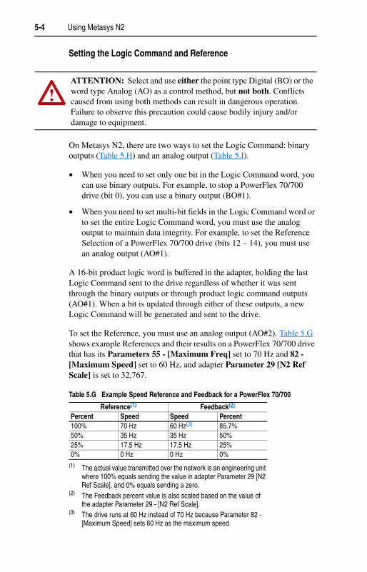
To set the Reference, you must use an analog output (AO#2). Table 5.G shows example References and their results on a PowerFlex 70/700 drive that has its Parameters 55 - [Maximum Freq] set to 70 Hz and 82 - [Maximum Speed] set to 60 Hz, and adapter Parameter 29 [N2 Ref Scale] is set to 32,767.
!ATTENTION: Select and use either the point type Digital (BO) or the word type Analog (AO) as a control method, but not both. Conflicts caused from using both methods can result in dangerous operation. Failure to observe this precaution could cause bodily injury and/or damage to equipment.
Table 5.G Example Speed Reference and Feedback for a PowerFlex 70/700
Reference(1)
(1) The actual value transmitted over the network is an engineering unit where 100% equals sending the value in adapter Parameter 29 [N2 Ref Scale], and 0% equals sending a zero.
Feedback(2)
(2) The Feedback percent value is also scaled based on the value of the adapter Parameter 29 - [N2 Ref Scale].
Percent Speed Speed Percent100% 70 Hz 60 Hz(3)
(3) The drive runs at 60 Hz instead of 70 Hz because Parameter 82 - [Maximum Speed] sets 60 Hz as the maximum speed.
85.7% 50% 35 Hz 35 Hz 50%25% 17.5 Hz 17.5 Hz 25%0% 0 Hz 0 Hz 0%
Using Metasys N2 5-5
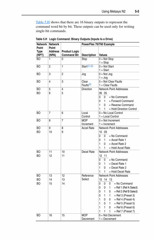
Table 5.H shows that there are 16 binary outputs to represent the command word bit by bit. These outputs can be used only for writing single-bit commands.
Table 5.H Logic Command: Binary Outputs (Inputs to a Drive)
Network Point Type (NPT)
Network Point Address (NPA)
Product Logic Command Bit
PowerFlex 70/700 Example
Description ValuesBO 1 0 Stop 0 = Not Stop
1 = StopBO 2 1 Start(1) (2) 0 = Not Start
1 = StartBO 3 2 Jog 0 = Not Jog
1 = JogBO 4 3 Clear
Faults(2)0 = Not Clear Faults1 = Clear Faults
BO 5 4 Direction Network Point AddressesBO 6 5 06 05
0 0 = No Command0 1 = Forward Command1 0 = Reverse Command1 1 = Hold Direction Control
BO 7 6 Local Control
0 = No Local Control1 = Local Control
BO 8 7 MOP Increment
0 = Not Increment1 = Increment
BO 9 8 Accel Rate Network Point AddressesBO 10 9 10 09
0 0 = No Command0 1 = Accel Rate 1 1 0 = Accel Rate 21 1 = Hold Accel Rate
BO 11 10 Decel Rate Network Point AddressesBO 12 11 12 11
0 0 = No Command0 1 = Decel Rate 1 1 0 = Decel Rate 21 1 = Hold Decel Rate
BO 13 12 Reference Select
Network Point AddressesBO 14 13 15 14 13BO 15 14 0 0 0 = No Command
0 0 1 = Ref 1 (Ref A Select)0 1 0 = Ref 2 (Ref B Select)0 1 1 = Ref 3 (Preset 3)1 0 0 = Ref 4 (Preset 4)1 0 1 = Ref 5 (Preset 5)1 1 0 = Ref 6 (Preset 6)1 1 1 = Ref 7 (Preset 7)
BO 16 15 MOP Decrement
0 = Not Decrement1 = Decrement

5-6 Using Metasys N2
Table 5.I shows the analog outputs. These outputs must be used for writing multi-bit commands and the Reference.
Viewing the Logic Status and Feedback
On Metasys N2, there are two ways to view the Logic Status: binary inputs (Table 5.J) and an analog input (Table 5.K). You can use binary inputs when you need to view only one bit in the Logic Status word. For example, to view whether a PowerFlex 70/700 drive is ready (bit 0), you can use a binary input (BI 1).
When you need to view multi-bit fields in the Logic Status word, to view the entire Logic Status word, or to view the Feedback word, you must use an analog input. For example, to view the local control of a PowerFlex 70/700 drive (bits 9 – 11), you must use an analog input (AI #1). To view the Feedback, you must use an analog input (AI #2 or AI #3).
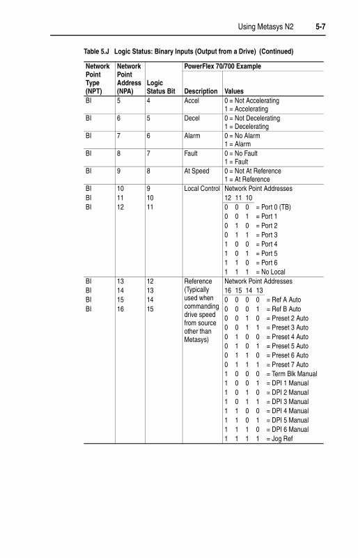
Table 5.J shows that there are 16 binary inputs to represent the status word bit by bit. These inputs can be used only for reading single-bit status.
(1) A 0 = Not Stop condition (logic 0) must first be present before a 1 = Start condition will start the drive.
(2) To perform this command, the value must change from “0” to “1.”
Table 5.I Logic Command and Reference: Analog Outputs
Network Point Type (NPT)
Network Point Address (NPA)
Parameter Description Range
AO 1 Product Logic Command
16-bit word. Bit definitions for PowerFlex 70/700 drives are in Table 5.H. For other products, refer to their documentation.
AO 2 Reference -100.0% to +100.0%
Table 5.J Logic Status: Binary Inputs (Output from a Drive)
Network Point Type (NPT)
Network Point Address (NPA)
Logic Status Bit
PowerFlex 70/700 Example
Description ValuesBI 1 0 Ready 0 = Not Ready
1 = ReadyBI 2 1 Active 0 = Not Running
1 = RunningBI 3 2 Command
Direction0 = Reverse1 = Forward
BI 4 3 Actual Direction
0 = Reverse1 = Forward
Using Metasys N2 5-7
BI 5 4 Accel 0 = Not Accelerating1 = Accelerating
BI 6 5 Decel 0 = Not Decelerating1 = Decelerating
BI 7 6 Alarm 0 = No Alarm1 = Alarm
BI 8 7 Fault 0 = No Fault1 = Fault
BI 9 8 At Speed 0 = Not At Reference1 = At Reference
BI 10 9 Local Control Network Point AddressesBI 11 10 12 11 10BI 12 11 0 0 0 = Port 0 (TB)
0 0 1 = Port 1 0 1 0 = Port 20 1 1 = Port 31 0 0 = Port 41 0 1 = Port 5 1 1 0 = Port 61 1 1 = No Local
BI 13 12 Reference (Typically used when commanding drive speed from source other than Metasys)
Network Point AddressesBI 14 13 16 15 14 13BI 15 14 0 0 0 0 = Ref A AutoBI 16 15 0 0 0 1 = Ref B Auto
0 0 1 0 = Preset 2 Auto0 0 1 1 = Preset 3 Auto0 1 0 0 = Preset 4 Auto0 1 0 1 = Preset 5 Auto0 1 1 0 = Preset 6 Auto0 1 1 1 = Preset 7 Auto1 0 0 0 = Term Blk Manual1 0 0 1 = DPI 1 Manual1 0 1 0 = DPI 2 Manual1 0 1 1 = DPI 3 Manual1 1 0 0 = DPI 4 Manual1 1 0 1 = DPI 5 Manual1 1 1 0 = DPI 6 Manual1 1 1 1 = Jog Ref
Table 5.J Logic Status: Binary Inputs (Output from a Drive) (Continued)
Network Point Type (NPT)
Network Point Address (NPA)
Logic Status Bit
PowerFlex 70/700 Example
Description Values
5-8 Using Metasys N2
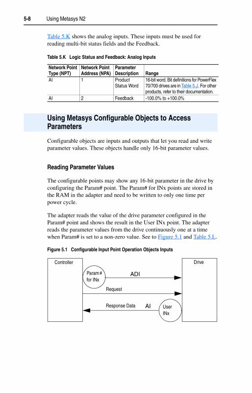
Table 5.K shows the analog inputs. These inputs must be used for reading multi-bit status fields and the Feedback.
Configurable objects are inputs and outputs that let you read and write parameter values. These objects handle only 16-bit parameter values.
Reading Parameter Values
The configurable points may show any 16-bit parameter in the drive by configuring the Param# point. The Param# for INx points are stored in the RAM in the adapter and need to be written to only one time per power cycle.
The adapter reads the value of the drive parameter configured in the Param# point and shows the result in the User INx point. The adapter reads the parameter values from the drive continuously one at a time when Param# is set to a non-zero value. See to Figure 5.1 and Table 5.L.
Figure 5.1 Configurable Input Point Operation Objects Inputs
Table 5.K Logic Status and Feedback: Analog Inputs
Network Point Type (NPT)
Network Point Address (NPA)
Parameter Description Range
AI 1 Product Status Word
16-bit word. Bit definitions for PowerFlex 70/700 drives are in Table 5.J. For other products, refer to their documentation.
AI 2 Feedback -100.0% to +100.0%
Using Metasys Configurable Objects to Access Parameters
Controller Drive
Param # for INx
User INx
Request
Response Data
ADI
AI

Using Metasys N2 5-9
Table 5.L Configurable Objects: Inputs
Network Point Type (NPT)
Network Point Address (NPA) Name Description Default
AI 3 User IN1 User-defined Input 1 0AI 4 User IN2 User-defined Input 2 0AI 5 User IN3 User-defined Input 3 0AI 6 User IN4 User-defined Input 4 0ADI 1 Param# for IN1 0 (not in use), 1 to
maximum # of drive parameters
0
ADI 2 Param# for IN2 0 (not in use), 1 to maximum # of drive parameters
0
ADI 3 Param# for IN3 0 (not in use), 1 to maximum # of drive parameters
0
ADI 4 Param# for IN4 0 (not in use), 1 to maximum # of drive parameters
0
Table 5.M Example of Configurable Objects: Inputs
Network Point Type (NPT)
Network Point Address Description Range [Scale]
SampleSetting
AI 3 Output Frequency +/-400 Hz [0.1 Hz] 60.0AI 4 Output Current 0.0 to Drive Rated Amps
[0.1 A]14.0
AI 5 Output Voltage 0.0 to Drive Rated Volts [0.1 VAC]
460.0
AI 6 Output Power 0.0 to Drive Rated kW [0.1 kW]
7.5
ADI 1 Param# for IN1 Integer# of drive parameter
1
ADI 2 Param# for IN2 Integer# of drive parameter
3
ADI 3 Param# for IN3 Integer# of drive parameter
6
ADI 4 Param# for IN4 Integer# of drive parameter
7

5-10 Using Metasys N2
Writing Parameter Values
These outputs are written from the adapter each time the User OUT point is written from the network.
A value of zero in the Param# field disables the writing of data for that specific point. Refer to the drive user manual for the desired parameter number.
Figure 5.2 Configurable Objects: Outputs
!ATTENTION: Risk of equipment damage exists. If configurable outputs are programmed to write parameter data to Non-Volatile Storage (NVS) frequently, the NVS will quickly exceed its life cycle and cause the drive to malfunction. Do not create a program that frequently uses configurable outputs to write parameter data to NVS. Datalinks do not write to NVS and should be used for frequently changed parameters.
Table 5.N Configurable Objects: Outputs
Network Point Type (NPT)
Network Point Address (NPA) Name Description Default
AO 3 User OUT1 User-defined Output 1 0AO 4 User OUT2 User-defined Output 2 0ADI 5 Param# for OUT1 0 (not in use), 1 to
maximum # of drive parameters
0
ADI 6 Param# for OUT2 0 (not in use), 1 to maximum # of drive parameters
0
Controller Drive
Param# for OUTx
User OUTx
ADI
AO
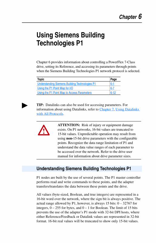
Chapter 6
Using Siemens Building Technologies P1
Chapter 6 provides information about controlling a PowerFlex 7-Class drive, setting its Reference, and accessing its parameters through points when the Siemens Building Technologies P1 network protocol is selected.
P1 nodes are built by the use of several points. The P1 master controller performs read and write commands to these points, and the adapter transfers/translates the data between these points and the drive.
All values (byte-sized, Boolean, and true integers) are represented in a 16-bit word over the network, where the sign bit is always positive. The actual range allowed by P1, however, is always 15 bits: 0 – 32767 for integers, 0 – 255 for bytes, and 0 – 1 for Boolean. The limit of 15 bits prevents the use of the adapter’s P1 mode with 32-bit DPI hosts, where either Reference/Feedback or Datalink values are represented in 32-bit format. 16-bit real values will be truncated to show only 15-bit values.
Topic PageUnderstanding Siemens Building Technologies P1 6-1Using the P1 Point Map for I/O 6-7Using the P1 Point Map to Access Parameters 6-12
TIP: Datalinks can also be used for accessing parameters. For information about using Datalinks, refer to Chapter 7, Using Datalinks with All Protocols.
!ATTENTION: Risk of injury or equipment damage exists. On P1 networks, 16-bit values are truncated to 15-bit values. Unpredictable operation may result from using non-15-bit drive parameters with the configurable points. Recognize the data range limitation of P1 and understand the data value ranges of each parameter to be accessed over the network. Refer to the drive user manual for information about drive parameter sizes.
Understanding Siemens Building Technologies P1
6-2 Using Siemens Building Technologies P1
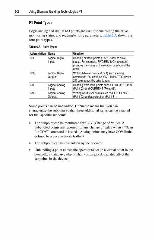
P1 Point Types
Logic analog and digital I/O points are used for controlling the drive, monitoring status, and reading/writing parameters. Table 6.A shows the four point types.
Some points can be unbundled. Unbundle means that you can characterize the subpoint so that three additional items can be enabled for that specific subpoint:
• The subpoint can be monitored for COV (Change of Value). All unbundled points are reported for any change of value when a “Scan for COV” command is issued. (Analog points may have COV limits defined to reduce network traffic.)
• The subpoint can be overridden by the operator.
• Unbundling a point allows the operator to set up a virtual point in the controller's database, which when commanded, can also affect the subpoints in the device.
Table 6.A Point Types
Abbreviation Name Used for LDI Logical Digital
InputsReading bit level points (0 or 1) such as drive status. For example, FWD.REV MON (point 21) provides the status of the rotation direction of the drive.
LDO Logical Digital Outputs
Writing bit-level points (0 or 1) such as drive commands. For example, CMD RUN.STOP (Point 24) commands the drive to run.
LAI Logical Analog Inputs
Reading word-level points such as FREQ OUTPUT (Point 03) and CURRENT (Point 06).
LAO Logical Analog Outputs
Writing word-level points such as REFERENCE (Point 92) and acceleration (Point 31).

Using Siemens Building Technologies P1 6-3
Siemens Building Technologies P1 Point MapTa
ble
6.B
Sie
men
s Bu
ildin
g Te
chno
logi
es P
1 Po
int L
ist
Poin
tNu
mbe
r(1)
(1)
Poin
ts n
ot li
sted
are
not
use
d in
this
app
licat
ion.
Poi
nt n
umbe
rs th
at a
ppea
r in
brac
es {
} may
be
unbu
ndle
d.
Poin
t Ty
pe(2
)
(2)
For a
des
crip
tion
of p
oint
type
s, re
fer t
o Ta
ble
6.A.
Not
e th
at th
e ou
tput
s an
d in
puts
are
from
the
netw
ork
pers
pect
ive, n
ot th
e dr
ive p
ersp
ectiv
e. F
or e
xam
ple,
an
LAO
is a
n ou
tput
from
the
cont
rolle
r on
the
netw
ork,
but
it is
an
inpu
t to
the
drive
.
Des
crip
tor
Engl
ish
Uni
tsSl
ope
Inte
rcep
tO
N T
ext
OFF
Tex
tDe
faul
tRa
nge
COV(3
)
(3)
CO
V in
dica
tes
whe
ther
the
poin
ts is
abl
e to
sup
port
CO
Vs a
nd o
verri
des.
Desc
riptio
n01
LAO
CTR
L AD
DR
ESS
10
990
– 25
5N
oN
ode
addr
ess
of th
is d
evic
e.02
LAO
APPL
ICAT
ION
10
2718
0 –
3276
7N
oFi
rmwa
re a
pplic
atio
n nu
mbe
r.{0
3}LA
IFR
EQ O
UTP
UT
HZ
0.01
-163
.83
00
– 32
767
Yes
Driv
e sp
eed
in fr
eque
ncy
(Her
tz).
{04}
LAI
PCT
OU
TPU
TPC
T0.
10
00
– 32
767
Yes
Driv
e sp
eed
in p
erce
ntag
e of
max
.{0
5}LA
ISP
EED
RPM
10
00
– 32
767
Yes
Driv
e sp
eed
in R
PM.
{06}
LAI
CU
RR
ENT
AMPS
0.1
00
0 –
3276
7Ye
sD
rive
curre
nt c
onsu
mpt
ion
in a
mps
.{0
7}LA
ITO
RQ
UE
PCT
0.1
-163
8.3
00
– 32
767
Yes
Driv
e to
rque
in p
erce
ntag
e of
max
.{0
8}LA
IPO
WER
KW0.
10
00
– 32
767
Yes
Driv
e po
wer
in k
W.
{09}
LAI
DR
IVE
TEM
PD
EG C
0.1
-163
8.3
00
– 32
767
Yes
Driv
e te
mpe
ratu
re in
deg
ree
C.{1
1}LA
ID
RIV
E M
WH
MW
H0.
10
00
– 32
767
Yes
Driv
e to
tal p
ower
con
sum
ptio
n in
M
WH
.{1
2}LA
IRU
N T
IME
HR
S0.
10
00
– 32
767
Yes
Driv
e to
tal r
un ti
me
in h
ours
.{1
3}LA
ID
C B
US
VOLT
VOLT
S0.
10
00
– 32
767
Yes
Driv
e D
C b
us v
olta
ge.
{20}
LAO
OVR
D T
IME
10
00
– 25
5Ye
sN
ot u
sed
by th
is a
pplic
atio
n.{2
1}LD
IFW
D.R
EV M
ON
10
REV
FWD
0 (F
WD
)0
– 1
Yes
Mon
itor t
he ro
tatio
n di
rect
ion
of th
e dr
ive.
{22}
LDO
CM
D F
WD.
REV
10
REV
FWD
0 (F
WD
)0
– 1
Yes
Com
man
d th
e ro
tatio
n di
rect
ion
of
the
driv
e.
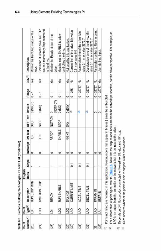
6-4 Using Siemens Building Technologies P1
Tabl
e 6.
B
Siem
ens
Bui
ldin
g Te
chno
logi
es P
1 Po
int L
ist (
Cont
inue
d)
Poin
tN
umbe
r(1)
(1)
Poin
ts n
ot li
sted
are
not
use
d in
this
app
licat
ion.
Poi
nt n
umbe
rs th
at a
ppea
r in
brac
es {
} may
be
unbu
ndle
d.
Poin
t Ty
pe(2
)
(2)
For a
des
crip
tion
of p
oint
type
s, re
fer t
o Ta
ble
6.A.
Not
e th
at th
e ou
tput
s an
d in
puts
are
from
the
netw
ork
pers
pect
ive,
not
the
drive
per
spec
tive.
For
exa
mpl
e, a
n LA
O is
an
outp
ut fr
om th
e co
ntro
ller o
n th
e ne
twor
k, b
ut it
is a
n in
put t
o th
e dr
ive.
Desc
ripto
rEn
glis
h Un
itsSl
ope
Inte
rcep
tO
N Te
xtO
FF T
ext
Defa
ult
Ran
geC
OV(4
)
(4)
CO
V in
dica
tes
whe
ther
the
poin
ts is
abl
e to
sup
port
CO
Vs a
nd o
verri
des.
Des
crip
tion
{23}
LDI
RUN
.STO
P M
ON
10
RUN
STO
P0
(STO
P)0
– 1
Yes
Mon
itor t
he R
un/S
top
stat
us o
f the
dr
ive.
{24}
LDO
CM
D R
UN
.STO
P1
0RU
NST
OP
0 (N
O)
0 –
1Ye
sC
omm
and
Run
to th
e dr
ive. A
STO
P is
sues
a m
omen
tary
Sto
p co
mm
and
to th
e dr
ive.
{25}
LDI
REA
DY1
0R
EADY
NO
TRDY
0 (NO
TRDY
)0
– 1
Yes
Mon
itor t
he R
eady
sta
tus
of th
e dr
ive.
{26}
LDO
RUN
EN
ABLE
10
ENAB
LEST
OP
0 (N
O)
0 –
1Ye
sM
ust b
e se
t to
ENAB
LE to
allo
w
cont
rollin
g th
e dr
ive.
{29}
LDO
DAY.
NG
T1
0N
IGH
TDA
Y0
(DAY
)0
– 1
Yes
Not
use
d by
this
app
licat
ion.
{30}
LAO
CU
RR
NT
LIM
IT0.
10
(3)
(3)
Dep
ends
on
DPI
Hos
t pro
duct
con
nect
ed to
(Pow
erFl
ex 7
0, e
tc.)
and
HP
size
.
0 –
255
No
Cur
rent
lim
it of
the
drive
. Min
val
ue
0.9;
max
val
ue 6
.0{3
1}LA
OAC
CEL
TIM
E0.
10
(3)
0 –
3276
7N
oAc
cele
ratio
n tim
e of
the
driv
e. M
in
valu
e 0.
1; m
ax v
alue
327
6.7
{32}
LAO
DEC
EL T
IME
0.1
0(3
)0
– 32
767
No
Dec
eler
atio
n tim
e of
the
drive
. Min
va
lue
0.1;
max
val
ue 3
276.
736
LAO
PAR
AM IN
10
00
– 32
767
No
Para
met
er n
umbe
r to
Use
r In
poin
t.{3
7}LA
IU
SER
IN1
00
0 –
3276
7Ye
sU
ser-d
efin
ed in
put.
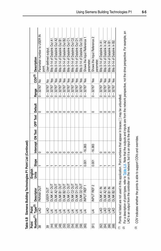
Using Siemens Building Technologies P1 6-5
Tabl
e 6.
B
Siem
ens
Bui
ldin
g Te
chno
logi
es P
1 Po
int L
ist (
Con
tinue
d)
Poin
tN
umbe
r(1)
(1)
Poin
ts n
ot li
sted
are
not
use
d in
this
app
licat
ion.
Poi
nt n
umbe
rs th
at a
ppea
r in
brac
es {
} may
be
unbu
ndle
d.
Poin
t Ty
pe(2
)
(2)
For a
des
crip
tion
of p
oint
type
s, re
fer t
o Ta
ble
6.A.
Not
e th
at th
e ou
tput
s an
d in
puts
are
from
the
netw
ork
pers
pect
ive, n
ot th
e dr
ive p
ersp
ectiv
e. F
or e
xam
ple,
an
LAO
is a
n ou
tput
from
the
cont
rolle
r on
the
netw
ork,
but
it is
an
inpu
t to
the
drive
.
Desc
ripto
rEn
glis
h Un
itsSl
ope
Inte
rcep
tO
N T
ext
OFF
Tex
tD
efau
ltRa
nge
CO
V(3)
(3)
CO
V in
dica
tes
whe
ther
the
poin
ts is
abl
e to
sup
port
CO
Vs a
nd o
verri
des.
Desc
riptio
n38
LAO
PAR
AM O
UT
10
00
– 32
767
No
Para
met
er n
umbe
r to
USE
R IN
po
int.
39LA
OU
SER
OU
T1
00
0 –
3276
7N
oU
ser-d
efin
ed o
utpu
t.{4
4}LA
ID
LNK
A1 O
UT
10
00
– 32
767
Yes
Bits
0-1
4 of
Dat
alin
k O
ut A
1.{4
6}LA
ID
LNK
A2 O
UT
10
00
– 32
767
Yes
Bits
0-1
4 of
Dat
alin
k O
ut A
2.{4
8}LA
ID
LNK
B1 O
UT
10
00
– 32
767
Yes
Bits
0-1
4 of
Dat
alin
k O
ut B
1.{5
0}LA
ID
LNK
B2 O
UT
10
00
– 32
767
Yes
Bits
0-1
4 of
Dat
alin
k O
ut B
2.{5
2}LA
ID
LNK
C1
OU
T1
00
0 –
3276
7Ye
sBi
ts 0
-14
of D
atal
ink
Out
C1.
{54}
LAI
DLN
K C
2 O
UT
10
00
– 32
767
Yes
Bits
0-1
4 of
Dat
alin
k O
ut C
2.{5
6}LA
ID
LNK
D1
OU
T1
00
0 –
3276
7Ye
sBi
ts 0
-14
of D
atal
ink
Out
D1.
{58}
LAI
DLN
K D
2 O
UT
10
00
– 32
767
Yes
Bits
0-1
4 of
Dat
alin
k O
ut D
2.{6
0}LA
IIN
PUT
REF
10.
001
-16.
383
00
– 32
767
Yes
Show
s th
e In
put R
efer
ence
1
para
met
er.
{61}
LAI
INPU
T R
EF 2
0.00
1-1
6.38
30
0 –
3276
7Ye
sSh
ows
the
Inpu
t Ref
eren
ce 2
pa
ram
eter
.{6
2}LA
OD
LNK
A1 IN
10
00
– 32
767
Yes
Bits
0-1
4 of
Dat
alin
k In
A1.
{64}
LAO
DLN
K A2
IN1
00
0 –
3276
7Ye
sBi
ts 0
-14
of D
atal
ink
In A
2{6
6}LA
OD
LNK
B1 IN
10
00
– 32
767
Yes
Bits
0-1
4 of
Dat
alin
k In
B1.
{68}
LAO
DLN
K B2
IN1
00
0 –
3276
7Ye
sBi
ts 0
-14
of D
atal
ink
In B
2.

6-6 Using Siemens Building Technologies P1
Tabl
e 6.
B S
iem
ens
Build
ing
Tech
nolo
gies
P1
Poin
t Lis
t (Co
ntin
ued)
Poin
tNu
mbe
r(1)
(1)
Poin
ts n
ot li
sted
are
not
use
d in
this
app
licat
ion.
Poi
nt n
umbe
rs th
at a
ppea
r in
brac
es {
} may
be
unbu
ndle
d.
Poin
t Ty
pe(2
)
(2)
For a
des
crip
tion
of p
oint
type
s, re
fer t
o Ta
ble
6.A.
Not
e th
at th
e ou
tput
s an
d in
puts
are
from
the
netw
ork
pers
pect
ive, n
ot th
e dr
ive p
ersp
ectiv
e. F
or e
xam
ple,
an
LAO
is a
n ou
tput
from
the
cont
rolle
r on
the
netw
ork,
but
it is
an
inpu
t to
the
drive
.
Desc
ripto
rEn
glis
h U
nits
Slop
eIn
terc
ept
ON
Text
OFF
Tex
tDe
faul
tR
ange
COV(3
)
(3)
CO
V in
dica
tes
whe
ther
the
poin
ts is
abl
e to
sup
port
CO
Vs a
nd o
verri
des.
Des
crip
tion
{70}
LAO
DLN
K C
1 IN
10
00
– 32
767
Yes
Bits
0-1
4 of
Dat
alin
k In
C1.
{72}
LAO
DLN
K C
2 IN
10
00
– 32
767
Yes
Bits
0-1
4 of
Dat
alin
k In
C2.
{74}
LAO
DLN
K D
1 IN
10
00
– 32
767
Yes
Bits
0-1
4 of
Dat
alin
k In
D1.
{76}
LAO
DLN
K D
2 IN
10
00
– 32
767
Yes
Bits
0-1
4 of
Dat
alin
k In
D2.
{89}
LAO
LOG
IC C
MD
LO
10
00
– 25
5Ye
sLo
wer
8 b
its o
f Pro
duct
Log
ic
Com
man
d W
ord.
{90}
LAO
LOG
IC C
MD
HI
10
00
– 25
5Ye
sH
ighe
r 8 b
its o
f Pro
duct
Log
ic
Com
man
d W
ord.
{91}
LAI
FEED
BAC
K1
00
0 –
3276
7Ye
sFe
edba
ck v
alue
bits
0-1
4 (a
bsol
ute
valu
e).
{92}
LAO
REF
EREN
CE
10
00
– 32
767
Yes
Ref
eren
ce v
alue
bits
0-1
4.{9
3}LD
IO
K.FA
ULT
10
FAU
LTO
K0
(OK)
0 –
1Ye
sSh
ows
if th
e dr
ive is
faul
ted
or n
ot.
{94}
LDO
RES
ET F
AULT
10
RES
ETN
OR
MAL
0 (NO
RM
AL)
0 –
1Ye
sR
eset
s th
e fa
ult c
ondi
tion
in th
e dr
ive. S
peci
al p
oint
. Will
retu
rn to
N
OR
MAL
(0) a
utom
atic
ally
{95}
LAI
LOG
IC S
TS L
O1
00
0 –
255
Yes
Low
er 8
bits
of P
rodu
ct L
ogic
Sta
tus
Wor
d.{9
6}LA
ILO
GIC
STS
HI
10
00
– 25
5Ye
sH
ighe
r 8 b
its o
f Pro
duct
Log
ic
Stat
us W
ord.
{99}
LAO
ERR
OR
STA
TUS
10
00
– 25
5Ye
sN
ot u
sed
by th
is a
pplic
atio
n.
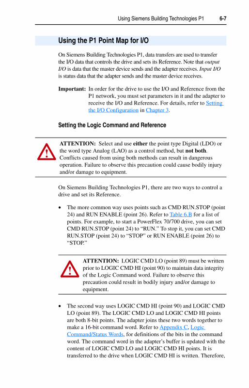
Using Siemens Building Technologies P1 6-7
On Siemens Building Technologies P1, data transfers are used to transfer the I/O data that controls the drive and sets its Reference. Note that output I/O is data that the master device sends and the adapter receives. Input I/O is status data that the adapter sends and the master device receives.
Important: In order for the drive to use the I/O and Reference from the P1 network, you must set parameters in it and the adapter to receive the I/O and Reference. For details, refer to Setting the I/O Configuration in Chapter 3.
Setting the Logic Command and Reference
On Siemens Building Technologies P1, there are two ways to control a drive and set its Reference.
• The more common way uses points such as CMD RUN.STOP (point 24) and RUN ENABLE (point 26). Refer to Table 6.B for a list of points. For example, to start a PowerFlex 70/700 drive, you can set CMD RUN.STOP (point 24) to “RUN.” To stop it, you can set CMD RUN.STOP (point 24) to “STOP” or RUN ENABLE (point 26) to “STOP.”
• The second way uses LOGIC CMD HI (point 90) and LOGIC CMD LO (point 89). The LOGIC CMD LO and LOGIC CMD HI points are both 8-bit points. The adapter joins these two words together to make a 16-bit command word. Refer to Appendix C, Logic Command/Status Words, for definitions of the bits in the command word. The command word in the adapter’s buffer is updated with the content of LOGIC CMD LO and LOGIC CMD HI points. It is transferred to the drive when LOGIC CMD HI is written. Therefore,
Using the P1 Point Map for I/O
!ATTENTION: Select and use either the point type Digital (LDO) or the word type Analog (LAO) as a control method, but not both. Conflicts caused from using both methods can result in dangerous operation. Failure to observe this precaution could cause bodily injury and/or damage to equipment.
!ATTENTION: LOGIC CMD LO (point 89) must be written prior to LOGIC CMD HI (point 90) to maintain data integrity of the Logic Command word. Failure to observe this precaution could result in bodily injury and/or damage to equipment.

6-8 Using Siemens Building Technologies P1
to maintain data integrity of the command word, LOGIC CMD LO must be written prior writing to LOGIC CMD HI. For example, to start a PowerFlex 70/700 drive, you can write a value of “2” to LOGIC CMD LO and a value of “0” to LOGIC CMD HI. To stop it, you can write a value of “1” to LOGIC CMD LO and a value of “0” to LOGIC CMD HI.
The Reference value is a 16-bit value in the drive but will only use 15 bits due to the P1 protocol limitation. You can send the reference using REFERENCE (point 92). Remember that the Reference value is a scaled engineering value. For example, in PowerFlex 70/700 drives, the reference is scaled based on the value of Parameter 55 - [Maximum Freq], but the commanded maximum speed can never exceed the value of Parameter 82 - [Maximum Speed]. Table 6.C shows example References and their results on a PowerFlex 70/700 drive that has its Parameters 55 - [Maximum Freq] set to 130 Hz and 82 - [Maximum Speed] set to 60 Hz.
Table 6.D shows the commands that you can execute on a PowerFlex 70/700 drive and the point(s) that you can use to execute them.
Table 6.C Example Speed Reference and Feedback for a PowerFlex 70/700
Reference Value
ScaleOutput Speed
Feedback ValuePercent Value
32767 100% 130 Hz 60 Hz(1)
(1) The drive runs at 60 Hz instead of 130 Hz because Parameter 82 - [Maximum Speed] sets 60 Hz as the maximum speed.
15123(2)
(2) The Feedback value is also scaled based on the value of Parameter 55 - [Maximum Freq], For example, 60/130 = 0.46 so 32767 x 0.46 = 15123.
16384 50% 65 Hz 60 Hz(1) 151238192 25% 32.5 Hz 32.5 Hz 81920 0% 0 Hz 0 Hz 0
Table 6.D Logic Commands
Point Number(s) Point
Logic Command Bit
PowerFlex 70/700 ExampleDescription Values
24 CMD RUN.STOP 0 Stop(1) 0 = Not Stop1 = Stop(3)26 RUN ENABLE
89 LOGIC CMD LO bit 0
24 CMD RUN.STOP 1 Start(1) (2) 0 = Not Start1 = Start89 LOGIC CMD LO
bit 189 LOGIC CMD LO
bit 22 Jog 0 = Not Jog
1 = Jog94 RESET FAULTS 3 Clear
Faults(2)0 = Not Clear Faults1 = Clear Faults89 LOGIC CMD LO
bit 3

Using Siemens Building Technologies P1 6-9
The P1 point map provides points to execute other commands on an adapter or drive. These points include CTRL ADDRESS (point 01), CURRENT LIMIT (point 30), ACCEL TIME (point 31), and DECEL TIME (point 32). Refer to Table 6.E on page 6-10 for a description of the various points.
22 CMD FWD.REV 4 and 5 Direction Bits89 LOGIC CMD LO 05 04
bits 4, 5 0 0 = No Command0 1 = Forward Command1 0 = Reverse Command1 1 = Hold Direction Control
89 LOGIC CMD LO bit 6
6 Local Control
0 = No Local Control1 = Local Control
89 LOGIC CMD LO bit 7
7 MOP Increment
0 = Not Increment1 = Increment
90 LOGIC CMD HI 8 and 9 Accel Rate LOGIC CMD HI Bitsbit 0, 1 01 00
0 0 = No Command0 1 = Accel Rate 1 1 0 = Accel Rate 21 1 = Hold Accel Rate
90 LOGIC CMD HI 10 and 11 Decel Rate LOGIC CMD HI Bitsbits 3, 2 03 02
0 0 = No Command0 1 = Decel Rate 1 1 0 = Decel Rate 21 1 = Hold Decel Rate
90 LOGIC CMD HI 12, 13, and 14 Reference Select
LOGIC CMD HI Bitsbits 6, 5, 4 06 05 04
0 0 0 = No Command0 0 1 = Ref 1 (Ref A Select)0 1 0 = Ref 2 (Ref B Select)0 1 1 = Ref 3 (Preset 3)1 0 0 = Ref 4 (Preset 4)1 0 1 = Ref 5 (Preset 5)1 1 0 = Ref 6 (Preset 6)1 1 1 = Ref 7 (Preset 7)
90 LOGIC CMD HI bit 7
15 MOP Decrement
0 = Not Decrement1 = Decrement
(1) A 0 = Not Stop condition (Logic Command bit 0) must first be present before a 1 = Start condition will start the drive.
(2) To perform this command, the value must change from “0” to “1.” (3) Setting CMD RUN.STOP to STOP issues a momentary Stop command to the drive. Logic
Command Bit 0 is momentarily set to 1 (STOP) to initiate a Stop and then set to 0 (Not Stop).
Table 6.D Logic Commands (Continued)
Point Number(s) Point
Logic Command Bit
PowerFlex 70/700 ExampleDescription Values
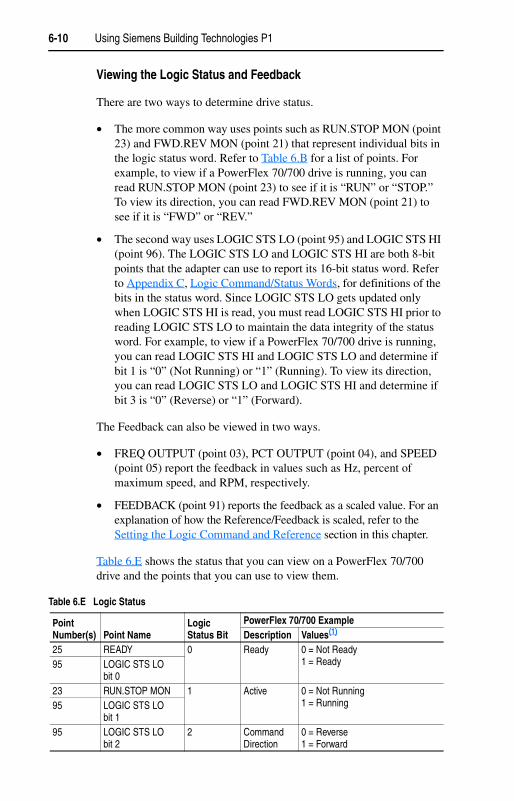
6-10 Using Siemens Building Technologies P1
Viewing the Logic Status and Feedback
There are two ways to determine drive status.
• The more common way uses points such as RUN.STOP MON (point 23) and FWD.REV MON (point 21) that represent individual bits in the logic status word. Refer to Table 6.B for a list of points. For example, to view if a PowerFlex 70/700 drive is running, you can read RUN.STOP MON (point 23) to see if it is “RUN” or “STOP.” To view its direction, you can read FWD.REV MON (point 21) to see if it is “FWD” or “REV.”
• The second way uses LOGIC STS LO (point 95) and LOGIC STS HI (point 96). The LOGIC STS LO and LOGIC STS HI are both 8-bit points that the adapter can use to report its 16-bit status word. Refer to Appendix C, Logic Command/Status Words, for definitions of the bits in the status word. Since LOGIC STS LO gets updated only when LOGIC STS HI is read, you must read LOGIC STS HI prior to reading LOGIC STS LO to maintain the data integrity of the status word. For example, to view if a PowerFlex 70/700 drive is running, you can read LOGIC STS HI and LOGIC STS LO and determine if bit 1 is “0” (Not Running) or “1” (Running). To view its direction, you can read LOGIC STS LO and LOGIC STS HI and determine if bit 3 is “0” (Reverse) or “1” (Forward).
The Feedback can also be viewed in two ways.
• FREQ OUTPUT (point 03), PCT OUTPUT (point 04), and SPEED (point 05) report the feedback in values such as Hz, percent of maximum speed, and RPM, respectively.
• FEEDBACK (point 91) reports the feedback as a scaled value. For an explanation of how the Reference/Feedback is scaled, refer to the Setting the Logic Command and Reference section in this chapter.
Table 6.E shows the status that you can view on a PowerFlex 70/700 drive and the points that you can use to view them.
Table 6.E Logic Status
Point Number(s) Point Name
Logic Status Bit
PowerFlex 70/700 ExampleDescription Values(1)
25 READY 0 Ready 0 = Not Ready1 = Ready95 LOGIC STS LO
bit 023 RUN.STOP MON 1 Active 0 = Not Running
1 = Running95 LOGIC STS LO bit 1
95 LOGIC STS LO bit 2
2 Command Direction
0 = Reverse1 = Forward

Using Siemens Building Technologies P1 6-11
21 FWD.REV MON 3 ActualDirection
0 = Reverse1 = Forward95 LOGIC STS LO
bit 395 LOGIC STS LO
bit 44 Accel 0 = Not Accelerating
1 = Accelerating95 LOGIC STS LO
bit 55 Decel 0 = Not Decelerating
1 = Decelerating95 LOGIC STS LO
bit 66 Alarm 0 = No Alarm
1 = Alarm93 OK.FAULT 7 Fault 0 = No Fault
1 = Fault95 LOGIC STS LO bit 7
96 LOGIC STS HI bit 0
8 At Speed 0 = Not At Reference1 = At Reference
96 LOGIC STS HI 9, 10, and 11 Local Control LOGIC STS HI Bitsbits 3, 2, 1 03 02 01
0 0 0 = Port 0 (TB)0 0 1 = Port 1 0 1 0 = Port 20 1 1 = Port 31 0 0 = Port 41 0 1 = Port 5 1 1 0 = Port 61 1 1 = No Local
96 LOGIC STS HI 12, 13, 14, and 15
Reference LOGIC STS HI Bitsbits 7, 6, 5, 4 07 06 05 04
0 0 0 0 = Ref A Auto0 0 0 1 = Ref B Auto0 0 1 0 = Preset 2 Auto0 0 1 1 = Preset 3 Auto0 1 0 0 = Preset 4 Auto0 1 0 1 = Preset 5 Auto0 1 1 0 = Preset 6 Auto0 1 1 1 = Preset 7 Auto1 0 0 0 = Term Blk Manual1 0 0 1 = DPI 1 Manual1 0 1 0 = DPI 2 Manual1 0 1 1 = DPI 3 Manual1 1 0 0 = DPI 4 Manual1 1 0 1 = DPI 5 Manual1 1 1 0 = DPI 6 Manual1 1 1 1 = Jog Ref
(1) The values in this column are for LOGIC STS LO (point 95) and LOGIC STS HI (point 96). For details about other point values, refer to Table 6.B on page 6-3.
Table 6.E Logic Status (Continued)
Point Number(s) Point Name
Logic Status Bit
PowerFlex 70/700 ExampleDescription Values(1)

6-12 Using Siemens Building Technologies P1
The P1 point map provides points to monitor a number of other features in the drive. These points include CURRENT (point 06), TORQUE (point 07), and POWER (point 08). Refer to Table 6.E on page 6-10 for a description of the various points.
Drive parameters can be accessed using Configurable Points or DataLinks (Chapter 7, Using Datalinks with Siemens P1).
Reading Parameter Values
Configurable points USER IN (point 37) and PARAM IN (point 36) are points that enable any parameter in the drive to be monitored. The USER IN shows only 15-bit values; therefore, only 16-bit drive parameters can be used (however, only values between 0 - 32767 would be used).
The PARAM IN is used to configure which parameter is to be monitored, and the value ends up in the USER IN.
For example, for a PowerFlex 70 or 700 drive, writing the value of ‘1’ into PARAM IN point (reading drive parameter 1) would provide the Output Frequency in USER IN point.
Writing Parameter Values
Configurable Points USER OUT (point 39) and PARAM OUT (point 38) are points that enable write access to any parameter in the drive. However, due to the 15-bit limitation, only 16-bit drive parameters should be accessed.
For example, for a PowerFlex 70/700 drive, writing a value of “140” in PARAM OUT (writing drive parameter 140) and the value of “200” in USER OUT would set drive Parameter 140 - [Accel Time 1] to 20.0 seconds.
Using the P1 Point Map to Access Parameters
!ATTENTION: Risk of equipment damage exists. If configurable points are programmed to write parameter data to Non-Volatile Storage (NVS) frequently, the NVS will quickly exceed its life cycle and cause the drive to malfunction. Do not create a program that frequently uses configurable points to write parameter data to NVS. Datalinks do not write to NVS and should be used for frequently changed parameters.

Chapter 7
Using Datalinks with All Protocols
Chapter 7 provides information and examples showing how to use Datalinks.
A Datalink is a mechanism used by PowerFlex drives to transfer data to and from the controller. Datalinks “point” to specific parameters to be accessed. When enabled, each Datalink consumes either two 16-bit or 32-bit words in both the input and output image depending on its size. The size of Datalinks (16-bit words or 32-bit words) is determined by the drive and displayed in Parameter 19 - [Datalink Size] in the adapter.
Rules for Using Datalinks
• Each set of Datalink parameters in a PowerFlex drive can be used by only one adapter. If more than one adapter is connected to a single drive, multiple adapters must not try to use the same Datalink.
• Parameter settings in the drive determine the data passed through the Datalink mechanism. Refer to the documentation for your drive.
• When you use a Datalink to change a value, the value is not written to the Non-Volatile Storage (NVS). The value is stored in volatile memory and lost when the drive loses power. Thus, use Datalinks when you need to change a value of a parameter frequently.
Topic PageUsing Datalinks 7-1Using Datalinks with Modbus
7-3
Using Datalinks with Metasys N2
7-6
Using Datalinks with Siemens P1
7-7
Using Datalinks
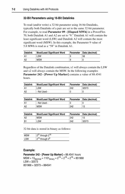
7-2 Using Datalinks with All Protocols
32-Bit Parameters using 16-Bit Datalinks
To read (and/or write) a 32-bit parameter using 16-bit Datalinks, typically both Datalinks of a pair are set to the same 32-bit parameter. For example, to read Parameter 09 - [Elapsed MWh] in a PowerFlex 70, both Datalink A1 and A2 are set to “9.” Datalink A1 will contain the least significant word (LSW) and Datalink A2 will contain the most significant word (MSW). In this example, the Parameter 9 value of 5.8 MWh is read as a “58” in Datalink A1.
Regardless of the Datalink combination, x1 will always contain the LSW and x2 will always contain the MSW. In the following examples Parameter 242 - [Power Up Marker] contains a value of 88.4541 hours.
32-bit data is stored in binary as follows:
Example: Parameter 242 - [Power Up Marker] = 88.4541 hoursMSW = 13decimal = 1101binary = 219 + 218 + 216 = 851968LSW = 32573851968 + 32573 = 884541
Datalink Most/Least Significant Word Parameter Data (decimal)A1 LSW 9 58A2 MSW 9 0
Datalink Most/Least Significant Word Parameter Data (decimal)A1 LSW 242 32573A2 - Not Used - 0 0
Datalink Most/Least Significant Word Parameter Data (decimal)A1 - Not Used - 0 0A2 MSW 242 13
Datalink Most/Least Significant Word Parameter Data (decimal)A2 MSW 242 13B1 LSW 242 32573
MSW 231 through 216
LSW 215 through 20

Using Datalinks with All Protocols 7-3
Configuring Datalinks
Configuring Datalinks from the drive side is a two-step process:
1. Configure the datalink parameters in the drive. For example, in a PowerFlex 70 or 700 drive, set Parameters 300 - [Data In A1] to 317 - [Data Out D2] to “point” to the parameters to be accessed. For instance, to read drive Parameter 1 - [Output Freq], set Parameter 310 - [Data Out A1] to “1.”
2. Enable the desired Datalinks in Parameter 16 - [DPI I/O Cfg] in the adapter. This tells the adapter to transfer Datalink data to and from the drive. For example, to enable Datalink A1, set bit 1 to “1.” For details, refer to Setting the I/O Configuration in Chapter 3.
This section presents information about using Datalinks with Modbus networks. For information about using Datalinks for Metasys N2 networks or Siemens P1 networks, refer to the Using Datalinks with Metasys N2 or Using Datalinks with Siemens P1 sections in this chapter.
Modbus Datalinks Out: A-D
Using Datalinks with Modbus
Table 7.A Modbus DPI Datalinks Out - A1, A2
Modbus Address Data Direction
Parameter Description 16-Bit Datalink 32-Bit Datalink
3x0012 Register Input Datalink A1 Out Not used LSW of 32-bit3x0013(1)
(1) A read access to address 3x0013 initiates a refresh of Datalink A1 value before reading.
Register Input Datalink A1 Out 16-bit value MSW of 32-bit3x0014 Register Input Datalink A2 Out Not used LSW of 32-bit3x0015(2)
(2) A read access to address 3x0015 initiates a refresh of Datalink A2 value before reading.
Register Input Datalink A2 Out 16-bit value MSW of 32-bit
Table 7.B Modbus Datalinks Out - B1, B2
Modbus Address Data Direction
Parameter Description 16-Bit Datalink 32-Bit Datalink
3x0016 Register Input Datalink B1 Out Not used LSW of 32-bit3x0017(1)
(1) A read access to address 3x0017 initiates a refresh of Datalink B1 value before reading.
Register Input Datalink B1 Out 16-bit value MSW of 32-bit3x0018 Register Input Datalink B2 Out Not used LSW of 32-bit3x0019(2)
(2) A read access to address 3x0019 initiates a refresh of Datalink B2 value before reading.
Register Input Datalink B2 Out 16-bit value MSW of 32-bit
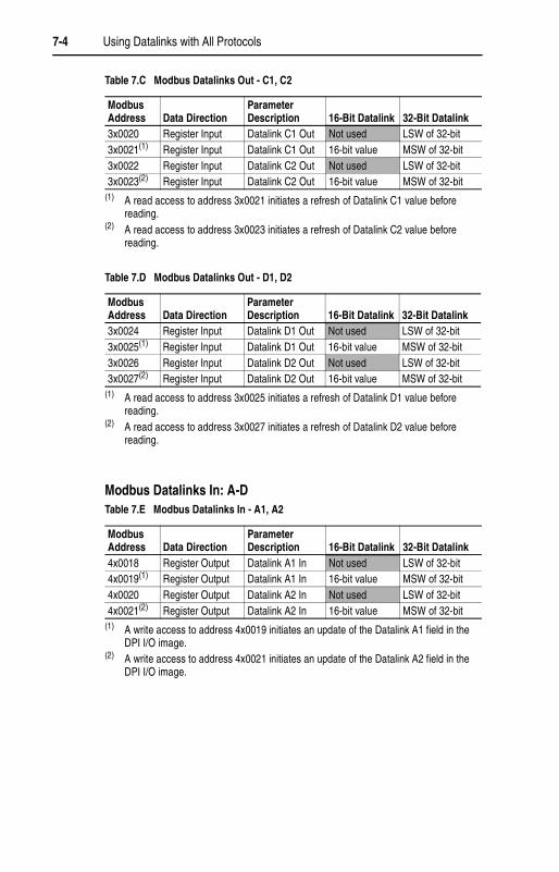
7-4 Using Datalinks with All Protocols
Modbus Datalinks In: A-D
Table 7.C Modbus Datalinks Out - C1, C2
Modbus Address Data Direction
Parameter Description 16-Bit Datalink 32-Bit Datalink
3x0020 Register Input Datalink C1 Out Not used LSW of 32-bit3x0021(1) Register Input Datalink C1 Out 16-bit value MSW of 32-bit3x0022 Register Input Datalink C2 Out Not used LSW of 32-bit3x0023(2) Register Input Datalink C2 Out 16-bit value MSW of 32-bit
(1) A read access to address 3x0021 initiates a refresh of Datalink C1 value before reading.
(2) A read access to address 3x0023 initiates a refresh of Datalink C2 value before reading.
Table 7.D Modbus Datalinks Out - D1, D2
Modbus Address Data Direction
Parameter Description 16-Bit Datalink 32-Bit Datalink
3x0024 Register Input Datalink D1 Out Not used LSW of 32-bit3x0025(1)
(1) A read access to address 3x0025 initiates a refresh of Datalink D1 value before reading.
Register Input Datalink D1 Out 16-bit value MSW of 32-bit3x0026 Register Input Datalink D2 Out Not used LSW of 32-bit3x0027(2)
(2) A read access to address 3x0027 initiates a refresh of Datalink D2 value before reading.
Register Input Datalink D2 Out 16-bit value MSW of 32-bit
Table 7.E Modbus Datalinks In - A1, A2
Modbus Address Data Direction
Parameter Description 16-Bit Datalink 32-Bit Datalink
4x0018 Register Output Datalink A1 In Not used LSW of 32-bit4x0019(1)
(1) A write access to address 4x0019 initiates an update of the Datalink A1 field in the DPI I/O image.
Register Output Datalink A1 In 16-bit value MSW of 32-bit4x0020 Register Output Datalink A2 In Not used LSW of 32-bit4x0021(2)
(2) A write access to address 4x0021 initiates an update of the Datalink A2 field in the DPI I/O image.
Register Output Datalink A2 In 16-bit value MSW of 32-bit

Using Datalinks with All Protocols 7-5
Table 7.F Modbus Datalinks In - B1, B2
Modbus Address Data Direction
Parameter Description 16-Bit Datalink 32-Bit Datalink
4x0022 Register Output Datalink B1 In Not used LSW of 32-bit4x0023(1)
(1) A write access to address 4x0023 initiates an update of the Datalink B1 field in the DPI I/O image.
Register Output Datalink B1 In 16-bit value MSW of 32-bit4x0024 Register Output Datalink B2 In Not used LSW of 32-bit4x0025(2)
(2) A write access to address 4x0025 initiates an update of the Datalink B2 field in the DPI I/O image.
Register Output Datalink B2 In 16-bit value MSW of 32-bit
Table 7.G Modbus Datalinks In - C1, C2
Modbus Address Data Direction
Parameter Description 16-Bit Datalink 32-Bit Datalink
4x0026 Register Output Datalink C1 In Not used LSW of 32-bit4x0027(1)
(1) A write access to address 4x0027 initiates an update of the Datalink C1 field in the DPI I/O image.
Register Output Datalink C1 In 16-bit value MSW of 32-bit4x0028 Register Output Datalink C2 In Not used LSW of 32-bit4x0029(2)
(2) A write access to address 4x0029 initiates an update of the Datalink C2 field in the DPI I/O image.
Register Output Datalink C2 In 16-bit value MSW of 32-bit
Table 7.H Modbus Datalinks In - D1, D2
Modbus Address Data Direction
Parameter Description 16-Bit Datalink 32-Bit Datalink
4x0030 Register Output Datalink D1 In Not used LSW of 32-bit4x0031(1)
(1) A write access to address 4x0031 initiates an update of the Datalink D1 field in the DPI I/O image.
Register Output Datalink D1 In 16-bit value MSW of 32-bit4x0032 Register Output Datalink D2 In Not used LSW of 32-bit4x0033(2)
(2) A write access to address 4x0033 initiates an update of the Datalink D2 field in the DPI I/O image.
Register Output Datalink D2 In 16-bit value MSW of 32-bit

7-6 Using Datalinks with All Protocols
This section presents information about using Datalinks with Metasys networks. For information about using Datalinks for Modbus networks or Siemens P1 networks, refer to the Using Datalinks with Modbus or Using Datalinks with Siemens P1 sections in this chapter.
Metasys N2 Datalinks Out: A & B (No Datalinks C & D)
Metasys N2 Datalinks In: A & B (No Datalinks C & D)
Using Datalinks with Metasys N2
Table 7.I Metasys N2 Datalinks Out - A1, A2
Network Point Type (NPT)
Network Point Address (NPA) Direction
Parameter Description
16-Bit Datalink
32-Bit Datalink
AI 7 Input Datalink A1 Out
16-bit value
Limited to -16,777,215 to +16,777,215
AI 8 Input Datalink A2 Out
16-bit value
Limited to -16,777,215 to +16,777,215
Table 7.J Metasys N2 Datalinks Out - B1, B2
Network Point Type (NPT)
Network Point Address (NPA) Direction
Parameter Description
16-Bit Datalink
32-Bit Datalink
AI 9 Input Datalink B1 Out
16-bit value
Limited to -16,777,215 to +16,777,215
AI 10 Input Datalink B2 Out
16-bit value
Limited to -16,777,215 to +16,777,215
Table 7.K Metasys N2 Datalinks In - A1, A2
Network Point Type (NPT)
Network Point Address (NPA) Direction
Parameter Description
16-Bit Datalink
32-Bit Datalink
AO 5 Output Datalink A1 In
16-bit value
Limited to -16,777,215 to +16,777,215
AO 6 Output Datalink A2 In
16-bit value
Limited to -16,777,215 to +16,777,215
Table 7.L Metasys N2 Datalinks In - B1, B2
Network Point Type (NPT)
Network Point Address (NPA) Direction
Parameter Description
16-Bit Datalink 32-Bit Datalink
AO 7 Output Datalink B1 In
16-bit value
Limited to -16,777,215 to +16,777,215
AO 8 Output Datalink B2 In
16-bit value
Limited to -16,777,215 to +16,777,215

Using Datalinks with All Protocols 7-7
This section presents information about using Datalinks with Siemens P1 networks. For information about using Datalinks for Modbus networks or Metasys N2 networks, refer to the Using Datalinks with Modbus or Using Datalinks with Metasys N2 sections in this chapter.
DLNK A1 OUT to DLNK D2 OUT contain the Datalink Out A1 to D2 parameters from the drive. DLNK A1 IN to DLNK D2 IN contain the Datalink In A1 to D2 parameter values to the drive.
For example, a PowerFlex 70 or 700 drive enabling Datalink A for the adapter and configuring drive Parameter 310 - [Data Out A1] to ‘1’ will provide drive Parameter 1 - [Output Frequency] at the DLNK A1 OUT point. Configuring Parameter 300 - [Data In A1] to ‘140’ in the drive will transfer the value of the DLNK A1 IN point value to drive Parameter 140 - [Accel Time 1] when accessed.
Note that certain drives may utilize 32-bit datalinks. In this case, Datalinks are not supported by the adapter. The adapter will support only 15-bit Datalink values.
Using Datalinks with Siemens P1
!ATTENTION: Risk of injury or equipment damage exists. On P1 networks, 16-bit values are truncated to 15-bit values. Unpredictable operation may result from using non-16-bit drive parameters with the configurable points. Recognize the data range limitation of P1 and understand the data value ranges of each parameter to be accessed over the network. Refer to the drive user manual for information about drive parameter sizes.
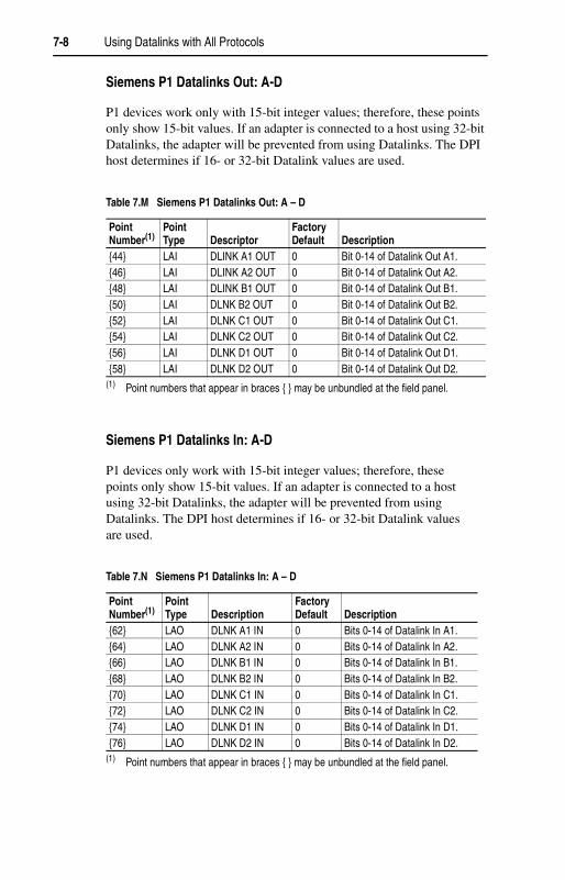
7-8 Using Datalinks with All Protocols
Siemens P1 Datalinks Out: A-D
P1 devices work only with 15-bit integer values; therefore, these points only show 15-bit values. If an adapter is connected to a host using 32-bit Datalinks, the adapter will be prevented from using Datalinks. The DPI host determines if 16- or 32-bit Datalink values are used.
Siemens P1 Datalinks In: A-D
P1 devices only work with 15-bit integer values; therefore, these points only show 15-bit values. If an adapter is connected to a host using 32-bit Datalinks, the adapter will be prevented from using Datalinks. The DPI host determines if 16- or 32-bit Datalink values are used.
Table 7.M Siemens P1 Datalinks Out: A – D
Point Number(1)
(1) Point numbers that appear in braces { } may be unbundled at the field panel.
Point Type Descriptor
Factory Default Description
{44} LAI DLINK A1 OUT 0 Bit 0-14 of Datalink Out A1.{46} LAI DLINK A2 OUT 0 Bit 0-14 of Datalink Out A2.{48} LAI DLINK B1 OUT 0 Bit 0-14 of Datalink Out B1.{50} LAI DLNK B2 OUT 0 Bit 0-14 of Datalink Out B2.{52} LAI DLNK C1 OUT 0 Bit 0-14 of Datalink Out C1.{54} LAI DLNK C2 OUT 0 Bit 0-14 of Datalink Out C2.{56} LAI DLNK D1 OUT 0 Bit 0-14 of Datalink Out D1.{58} LAI DLNK D2 OUT 0 Bit 0-14 of Datalink Out D2.
Table 7.N Siemens P1 Datalinks In: A – D
Point Number(1)
(1) Point numbers that appear in braces { } may be unbundled at the field panel.
Point Type Description
Factory Default Description
{62} LAO DLNK A1 IN 0 Bits 0-14 of Datalink In A1.{64} LAO DLNK A2 IN 0 Bits 0-14 of Datalink In A2.{66} LAO DLNK B1 IN 0 Bits 0-14 of Datalink In B1.{68} LAO DLNK B2 IN 0 Bits 0-14 of Datalink In B2.{70} LAO DLNK C1 IN 0 Bits 0-14 of Datalink In C1.{72} LAO DLNK C2 IN 0 Bits 0-14 of Datalink In C2.{74} LAO DLNK D1 IN 0 Bits 0-14 of Datalink In D1.{76} LAO DLNK D2 IN 0 Bits 0-14 of Datalink In D2.

Chapter 8
Troubleshooting
Chapter 8 provides information for troubleshooting potential problems with the adapter and network.
The RS-485 HVAC adapter has four status indicators. They can be viewed on the adapter or through the drive cover.
Figure 8.1 Status Indicators (location on drive may vary)
Topic Page Topic PageLocating the Status Indicators 8-1 NET B Status Indicator 8-4PORT Status Indicator 8-2 Viewing and Clearing Adapter
Diagnostic Items8-5
MOD Status Indicator 8-3NET A Status Indicator 8-4 Viewing and Clearing Events 8-8
Locating the Status Indicators
# Status Indicator
Description Page
� PORT DPI Connection Status 8-2� MOD Adapter Status 8-3� NET A Serial Communication Status 8-4� NET B Serial Communication Traffic Status 8-4
PWR
STS
PORT
MOD
NET A
NET B
��
��
��
��
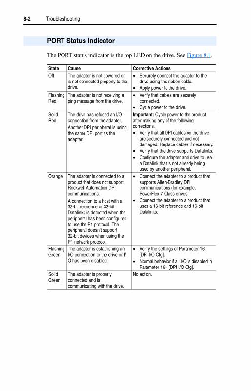
8-2 Troubleshooting
The PORT status indicator is the top LED on the drive. See Figure 8.1.
PORT Status Indicator
State Cause Corrective ActionsOff The adapter is not powered or
is not connected properly to the drive.
• Securely connect the adapter to the drive using the ribbon cable.
• Apply power to the drive.Flashing Red
The adapter is not receiving a ping message from the drive.
• Verify that cables are securely connected.
• Cycle power to the drive.Solid Red
The drive has refused an I/O connection from the adapter.Another DPI peripheral is using the same DPI port as the adapter.
Important: Cycle power to the product after making any of the following corrections.• Verify that all DPI cables on the drive
are securely connected and not damaged. Replace cables if necessary.
• Verify that the drive supports Datalinks.• Configure the adapter and drive to use
a Datalink that is not already being used by another peripheral.
Orange The adapter is connected to a product that does not support Rockwell Automation DPI communications.A connection to a host with a 32-bit reference or 32-bit Datalinks is detected when the peripheral has been configured to use the P1 protocol. The peripheral doesn’t support 32-bit devices when using the P1 network protocol.
• Connect the adapter to a product that supports Allen-Bradley DPI communications (for example, PowerFlex 7-Class drives).
• Connect the adapter to a product that uses a 16-bit reference and 16-bit Datalinks.
Flashing Green
The adapter is establishing an I/O connection to the drive or I/O has been disabled.
• Verify the settings of Parameter 16 - [DPI I/O Cfg].
• Normal behavior if all I/O is disabled in Parameter 16 - [DPI I/O Cfg].
Solid Green
The adapter is properly connected and is communicating with the drive.
No action.

Troubleshooting 8-3
The MOD status indicator is the second LED from the top on the drive. See Figure 8.1.
MOD Status Indicator
State Cause Corrective ActionsOff The adapter is not powered. • Securely connect the adapter to the
drive using the ribbon cable.• Apply power to the drive.
Flashing Red
Bad CRC of adapter parameters or Flash program; other recoverable fault condition.
• Clear any faults in the adapter.• Cycle power to the drive.• If cycling power does not correct the
problem, the parameter settings may have been corrupted. Reset faults and reconfigure the adapter.
• If resetting defaults does not correct the problem, flash the adapter with the latest firmware release.
Solid Red
The adapter has failed the hardware test.
• Cycle power to the drive.• Replace the adapter.
Flashing Green
The adapter is operational, but is not transferring I/O data.
• Place the scanner in RUN mode.• Program the controller to recognize
and transmit I/O to the adapter.• Configure the adapter for the program
in the controller.• Normal behavior if all I/O has been
disabled in Parameter 16 - [DPI I/O Cfg].
Solid Green
The adapter is operational and transferring I/O data.
No action.
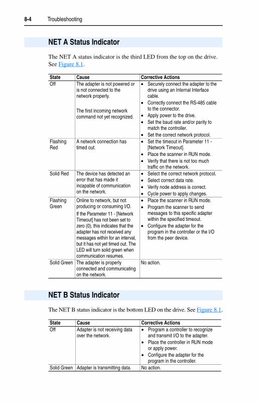
8-4 Troubleshooting
The NET A status indicator is the third LED from the top on the drive. See Figure 8.1.
The NET B status indicator is the bottom LED on the drive. See Figure 8.1.
NET A Status Indicator
State Cause Corrective ActionsOff The adapter is not powered or
is not connected to the network properly.
The first incoming network command not yet recognized.
• Securely connect the adapter to the drive using an Internal Interface cable.
• Correctly connect the RS-485 cable to the connector.
• Apply power to the drive.• Set the baud rate and/or parity to
match the controller.• Set the correct network protocol.
Flashing Red
A network connection has timed out.
• Set the timeout in Parameter 11 - [Network Timeout].
• Place the scanner in RUN mode.• Verify that there is not too much
traffic on the network.Solid Red The device has detected an
error that has made it incapable of communication on the network.
• Select the correct network protocol.• Select correct data rate.• Verify node address is correct.• Cycle power to apply changes.
Flashing Green
Online to network, but not producing or consuming I/O.If the Parameter 11 - [Network Timeout] has not been set to zero (0), this indicates that the adapter has not received any messages within for an interval, but it has not yet timed out. The LED will turn solid green when communication resumes.
• Place the scanner in RUN mode.• Program the scanner to send
messages to this specific adapter within the specified timeout.
• Configure the adapter for the program in the controller or the I/O from the peer device.
Solid Green The adapter is properly connected and communicating on the network.
No action.
NET B Status Indicator
State Cause Corrective ActionsOff Adapter is not receiving data
over the network.• Program a controller to recognize
and transmit I/O to the adapter.• Place the controller in RUN mode
or apply power.• Configure the adapter for the
program in the controller.Solid Green Adapter is transmitting data. No action.
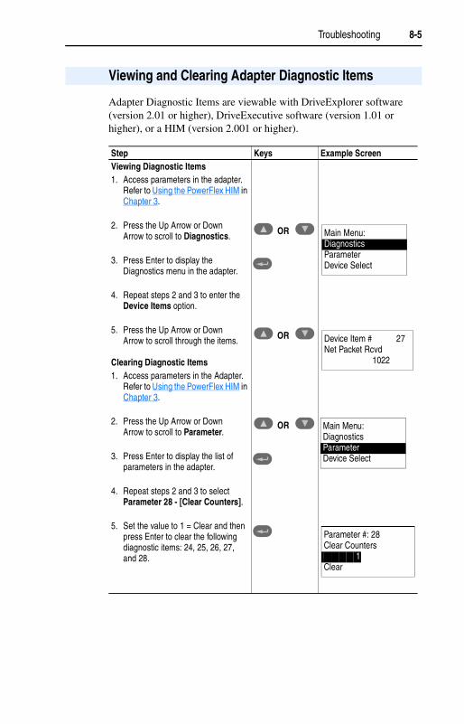
Troubleshooting 8-5
Adapter Diagnostic Items are viewable with DriveExplorer software (version 2.01 or higher), DriveExecutive software (version 1.01 or higher), or a HIM (version 2.001 or higher).
Viewing and Clearing Adapter Diagnostic Items
Step Keys Example ScreenViewing Diagnostic Items1. Access parameters in the adapter.
Refer to Using the PowerFlex HIM in Chapter 3.
2. Press the Up Arrow or Down Arrow to scroll to Diagnostics.
3. Press Enter to display the Diagnostics menu in the adapter.
4. Repeat steps 2 and 3 to enter the Device Items option.
5. Press the Up Arrow or Down Arrow to scroll through the items.
Clearing Diagnostic Items1. Access parameters in the Adapter.
Refer to Using the PowerFlex HIM in Chapter 3.
2. Press the Up Arrow or Down Arrow to scroll to Parameter.
3. Press Enter to display the list of parameters in the adapter.
4. Repeat steps 2 and 3 to select Parameter 28 - [Clear Counters].
5. Set the value to 1 = Clear and then press Enter to clear the following diagnostic items: 24, 25, 26, 27, and 28.
OR
OR
OR
Main Menu:DiagnosticsParameterDevice Select
Device Item # 27Net Packet Rcvd
1022
Parameter #: 28Clear Counters
1Clear
Main Menu:DiagnosticsParameterDevice Select
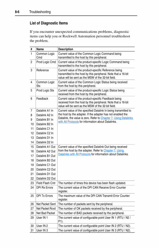
8-6 Troubleshooting
List of Diagnostic Items
If you encounter unexpected communications problems, diagnostic items can help you or Rockwell Automation personnel troubleshoot the problem.
# Name Description1 Common Logic
CmdCurrent value of the Common Logic Command being transmitted to the host by this peripheral.
2 Prod Logic Cmd Current value of the product-specific Logic Command being transmitted to the host by this peripheral.
3 Reference Current value of the product-specific Reference being transmitted to the host by this peripheral. Note that a 16-bit value will be sent as the MSW of the 32-bit field.
4 Common Logic Sts
Current value of the Common Logic Status being received from the host by this peripheral.
5 Prod Logic Sts Current value of the product-specific Logic Status being received from the host by this peripheral.
6 Feedback Current value of the product-specific Feedback being received from the host by this peripheral. Note that a 16-bit value will be sent as the MSW of the 32-bit field.
7891011121314
Datalink A1 InDatalink A2 InDatalink B1 InDatalink B2 InDatalink C1 InDatalink C2 InDatalink D1 InDatalink D2 In
Current value of the specified Datalink In being transmitted to the host by the adapter. If the adapter has not enabled the Datalink, the value is zero. Refer to Chapter 7, Using Datalinks with All Protocols for information about Datalinks.
1516171819202122
Datalink A1 OutDatalink A2 OutDatalink B1 OutDatalink B2 OutDatalink C1 OutDatalink C2 OutDatalink D1 OutDatalink D2 Out
Current value of the specified Datalink Out being received from the host by the adapter. Refer to Chapter 7, Using Datalinks with All Protocols for information about Datalinks.
23 Field Flash Cntr The number of times this device has been flash updated.24 DPI Rx Errors The current value of the DPI CAN Receive Error Counter
register.25 DPI Tx Errors The maximum value of the DPI CAN Transmit Error Counter
register.26 Net Packet Sent The number of packets sent by the peripheral.27 Net Packet Rcvd The number of OK packets received by the peripheral.28 Net Bad Packet The number of BAD packets received by the peripheral.29 User IN 1 The current value of configurable point User IN 1 (RTU / N2 /
P1).30 User IN 2 The current value of configurable point User IN 2 (RTU / N2).31 User IN 3 The current value of configurable point User IN 3 (RTU / N2).

Troubleshooting 8-7
32 User IN 4 The current value of configurable point User IN 4 (RTU / N2).33 User IN 5 The current value of configurable point User IN 5 (RTU / N2).34 User IN 6 The current value of configurable point User IN 6 (RTU / N2).35 User IN 7 The current value of configurable point User IN 7 (RTU / N2).36 User IN 8 The current value of configurable point User IN 8 (RTU / N2).37 User OUT 1 The current value of configurable point User OUT 1 (RTU / N2 /
P1).38 User OUT 2 The current value of configurable point User OUT 2 (RTU / N2).39 User OUT 3 The current value of configurable point User OUT 3 (RTU / N2).40 Switch 1 The current value of Rotary Switch 1 (Protocol Select).41 Switch 2 The current value of Rotary Switch 2 (Node Address ones digit).42 Switch 3 The current value of Rotary Switch 3 (Node Address tens digit).
# Name Description
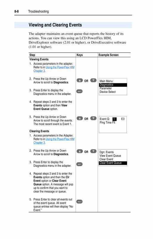
8-8 Troubleshooting
The adapter maintains an event queue that reports the history of its actions. You can view this using an LCD PowerFlex HIM, DriveExplorer software (2.01 or higher), or DriveExecutive software (1.01 or higher).
Viewing and Clearing Events
Step Keys Example ScreenViewing Events1. Access parameters in the adapter.
Refer to in Using the PowerFlex HIM Chapter 3.
2. Press the Up Arrow or Down Arrow to scroll to Diagnostics.
3. Press Enter to display the Diagnostics menu in the adapter.
4. Repeat steps 2 and 3 to enter the Events option and then View Event Queue option.
5. Press the Up Arrow or Down Arrow to scroll through the events. The most recent event is Event 1.
Clearing Events1. Access parameters in the Adapter.
Refer to in Using the PowerFlex HIM Chapter 3.
2. Press the Up Arrow or Down Arrow to scroll to Diagnostics.
3. Press Enter to display the Diagnostics menu in the adapter.
4. Repeat steps 2 and 3 to enter the Events option and then the Clr Event option or Clear Event Queue option. A message will pop up to confirm that you want to clear the message or queue.
5. Press Enter to clear all events out of the event queue. All event queue entries will then display “No Event.”
OR
OR
OR
Main Menu:DiagnosticsParameterDevice Select
Event Q: 1 E3Ping Time Flt
Dgn: EventsView Event QueueClear EventClear Event Queue

Troubleshooting 8-9
Events
Many events in the Event queue occur under normal operation. If you encounter unexpected communications problems, the events can help you or Rockwell Automation personnel troubleshoot the problem. The following events may appear in the event queue:
Code Event Description1 No Event Empty event queue entry.2 DPI Bus Off Flt A bus off condition was detected on DPI. This event
may be caused by loose or broken cables or by noise.3 Ping Time Flt A ping message was not received on DPI within the
specified time.4 Port ID Flt The debounced DPI Ping ID was read as zero or seven
after the peripheral had completed start up.5 Port Change Flt The DPI port changed after start up.6 Host Sent Reset The drive issued a reset event.7 EEPROM Sum Flt The EEPROM in the adapter is corrupt.8 Online @ 125 kbps The peripheral detects that the host is at 125 kbps.9 Online @ 500 kbps The peripheral detects that the host is at 500 kbps.10 Bad Host Flt The adapter was connected to an incompatible
product.11 Dup Port Flt Another peripheral with the same port number is
already in use.12 Type 0 Login The adapter has logged in for Type 0 control.13 Type 0 Time Flt The adapter has not received a Type 0 status message
within the specified time.14 DL Login The adapter has logged into a Datalink.15 DL Reject Flt The host rejected an attempt to log in to a Datalink.16 DL Time Flt The adapter has not received a Datalink message
within the specified time.17 Control Disabled The adapter has sent a “Soft Control Disable”
command to the DPI product.18 Control Enabled The adapter has sent a “Soft Control Enable” command
to the host.19 Message Timeout A client-server message sent by the peripheral was not
completed within one second.20 DPI Fault Msg The DPI Host has faulted.21 DPI Fault Clear The user cleared a fault in the adapter.22 Normal Startup The adapter successfully started up.23 Fault Cfg Error The peripheral detected a 32-bit fault configuration
reference when the host supports only a 16-bit reference, or detected a 32-bit fault configuration Datalink value when the host supports only 16-bit Datalinks.
24 Net Comm Flt The peripheral detected a communication fault on the network.

8-10 Troubleshooting
25 Net Detected The peripheral has detected network communication.26 Net TImeout Flt The peripheral has detected a network timeout. The
timeout period is configured in parameter 11, Network Timeout.
27 Lang CRC Bad The CRC of the language Text file is incorrect.
Code Event Description

Appendix A
Specifications
Appendix A presents the specifications for the adapter.
Topic Page Topic PageCommunications A-1 Environmental A-2Electrical A-1 Regulatory Compliance A-2Mechanical A-2
Communications
Network Protocols
Data Rates- Modbus RTU- Metasys N2- Siemens Building Technologies P1
Modbus RTUMetasys N2Siemens Building Technologies P1
4800, 9600, 19200, 38400 baud9600 baud4800, 9600 baud
DriveProtocolData Rates
DPI125K or 500K
Electrical
ConsumptionDriveNetwork
150 mA at 5VNone

A-2 Specifications
Mechanical
DimensionsHeightLengthWidth
19 mm (0.75 in.)86 mm (3.33 in.)78.5 mm (3.09 in.)
Weight 85 g. (3 oz.)
Environmental
TemperatureOperatingStorage
-10 to 50° C (14 to 149° F)-40 to 85° C (-40 to 185° F)
Relative Humidity 5 to 95% non-condensing
Atmosphere Important: The adapter must not be installed in an area where the ambient atmosphere contains volatile or corrosive gas, vapors or dust. If the adapter is not going to be installed for a period of time, it must be stored in an area where it will not be exposed to a corrosive atmosphere.
Regulatory Compliance
Certification SpecificationUL UL508CcUL CAN / CSA C22.2 No. 14-M91CE EN50178 and EN61800-3

Appendix B
Adapter Parameters
Appendix B presents information about the adapter parameters.
Topic PageParameter List B-1
Parameter List
Parameter No. Name and Description Details01 [DPI Port]
Displays the port to which the adapter is connected. This will usually be port 5.
Default: 5Minimum: 0Maximum: 7Type: Read Only
02 [DPI Data Rate]Displays the data rate used by the drive. This data rate is set in the drive, and the adapter detects it.
Default: 0 = 125 KValues: 0 = 125 K
1 = 500 KType: Read Only
03 [Net Addr Cfg]Configures the network node address if the network switches on the adapter are set to 00.
Default: 1Minimum: 0Maximum: 247Type: Read/WriteReset Required: Yes
04 [Net Addr Act]Displays the actual network address.
Default: 1Minimum: 0Maximum: 247Type: Read Only
05 [Net Rate Cfg]Configures the network data rate.
The available values for this parameter depend on the network protocol selected. Only valid values for the specified network are displayed.
Default: 1 = 9600Values: 0 = 4800
1 = 96002 = 192003 = 38400
Type: Read/WriteReset Required: Yes
06 [Net Rate Act]Displays the network data rate actually used by the adapter.
Default: 1 = 9600Values: 0 = 4800
1 = 96002 = 192003 = 38400
Type: Read Only

B-2 Adapter Parameters
07 [Net Parity Cfg]Configures the network parity.
The available values for this parameter depend on the network protocol selected. Only valid values for the specified network are displayed.
Default: 0 = NoneValues: 0 = None
1 = Odd2 = Even
Type: Read/WriteReset Required: Yes
08 [Net Parity Act]Displays the actual network parity used by the adapter.
Default: 0 = NoneValues: 0 = None
1 = Odd2 = Even
Type: Read Only09 [Net Stop Bits]
Displays the number of stop bits used by the selected protocol.
This value is network-dependent:• Metasys N2 and Siemens Building
Technologies P1 protocols use only 1 bit, so the adapter shows only this value.
• The number of stop bits used when using the ModBus RTU protocol depends on the type of parity used by the adapter (see Parameter 07 - [Net Parity Cfg]). If the value is “none,” the adapter uses 2 stop bits; otherwise, it uses only 1 stop bit.
Default: 0 = 1 bitValues: 0 = 1 bit
1 = 2 bitsType: Read Only
10 [Net Chksum Type]Displays the type of checksum used by the selected protocol. The values are as follows:• CRC16 (0) is Cyclic Redundancy Check with
0 as a seed value. The Siemens Building Technologies P1 protocol uses this checksum.
• RLC is Run Length Checksum. The Metasys N2 protocol uses this checksum.
• CRC16 (-1) is Cyclic Redundancy Check with -1 as a seed value. The Modbus RTU protocol uses this checksum.
Default: 0 = CRC16 (0)Values: 0 = CRC16 (0)
1 = RLC2 = CRC16 (-1)
Type: Read Only
11 [Network Timeout]Configures the time in seconds to be used to detect network communication loss.
Default: 10 SecondsMinimum: 0 Seconds (No Detection)Maximum: 180 SecondsType: Read/WriteReset Required: No
Parameter No. Name and Description Details
!ATTENTION: Risk of injury or equipment damage exists. Parameter 11 - [Network Timeout] lets you determine how long it will take your adapter to detect network communication losses. By default, this parameter sets the timeout to ten seconds. You can set it so that the duration is shorter, longer, or disabled. Take precautions to ensure that the setting does not create a risk of injury or equipment damage. When commissioning the drive, verify that your system responds correctly to various situations (for example, a disconnected cable).

Adapter Parameters B-3
12 [Ref / Fdbk Size]Displays the size of the Reference/Feedback. The drive determines the size of the Reference/Feedback.
Default: 0 = 16-bitValues: 0 = 16-bit
1 = 32-bitType: Read Only
13 [Datalink Size]Displays the size of each datalink. The drive determines the size of Datalinks.
Default: 0 = 16-bitValues: 0 = 16-bit
1 = 32-bitType: Read Only
14 [Reset Module]No action if set to “Ready.” Resets the adapter if set to “Reset Module.” Restores the adapter to its factory default settings if set to “Set Defaults.” This parameter is a command. It will be reset to “0 = Ready” after the command has been performed.
Default: 0 = ReadyValues 0 = Ready
1 = Reset Module2 = Set Defaults
Type: Read/WriteReset Required: No
15 [Comm Flt Action]Sets the action that the adapter will take if it detects a network failure because it has not communicated with its master within the interval specified in Parameter 11 - [Network Timeout]. This action takes effective only if I/O that controls the drive is transmitted through the adapter.
Default: 0 = FaultValues: 0 = Fault
1 = Stop2 = Zero Data3 = Hold Last4 = Send Flt Cfg
Type: Read/WriteReset Required: No
16 [DPI I/O Cfg]Configures the I/O to be transferred through the adapter.
Default: xxx0 0001Bit Values: 0 = I/O disabled
1 = I/O enabledType: Read/WriteReset Required: YesBit Definitions0 = Cmd/Ref1 = Datalink A2 = Datalink B3 = Datalink C (Not used with Metasys N2)4 = Datalink D (Not used with Metasys N2)5 = Not Used6 = Not Used7 = Not Used
Parameter No. Name and Description Details
!ATTENTION: Risk of injury or equipment damage exists. If the adapter is transmitting I/O that controls the drive, the drive may fault when you reset the adapter. Determine how your drive will respond before resetting a connected adapter.
!ATTENTION: Risk of injury or equipment damage exists. Parameter 15 - [Comm Flt Action] lets you determine the action of the adapter and connected drive if communications are disrupted. By default, this parameter faults the drive. You can set this parameter so that the drive continues to run. Precautions should be taken to ensure that the setting of this parameter does not create a risk of injury or equipment damage. When commissioning the drive, verify that your system responds correctly to various situations (for example, a disconnected cable).
BitDefault 10000x xx
0123457 6
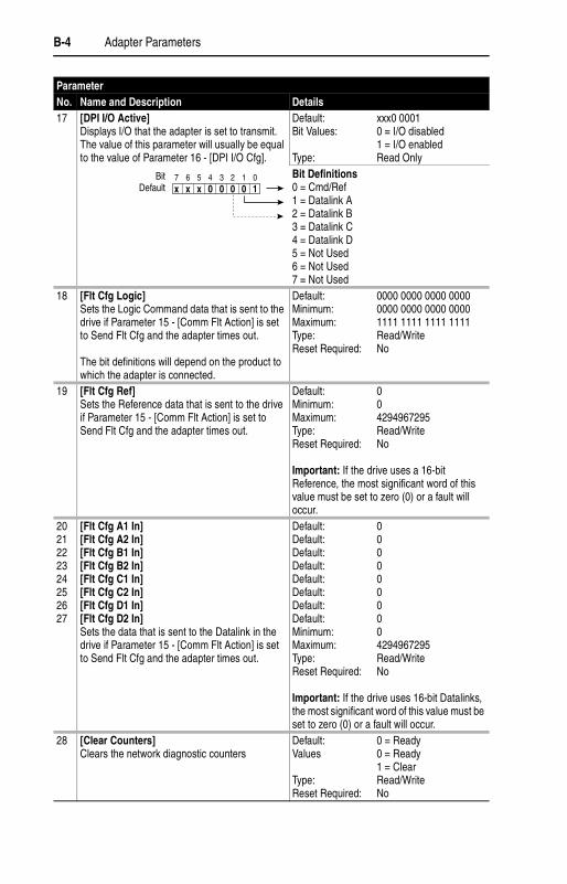
B-4 Adapter Parameters
17 [DPI I/O Active]Displays I/O that the adapter is set to transmit. The value of this parameter will usually be equal to the value of Parameter 16 - [DPI I/O Cfg].
Default: xxx0 0001Bit Values: 0 = I/O disabled
1 = I/O enabledType: Read OnlyBit Definitions0 = Cmd/Ref1 = Datalink A2 = Datalink B3 = Datalink C4 = Datalink D5 = Not Used6 = Not Used7 = Not Used
18 [Flt Cfg Logic]Sets the Logic Command data that is sent to the drive if Parameter 15 - [Comm Flt Action] is set to Send Flt Cfg and the adapter times out.
The bit definitions will depend on the product to which the adapter is connected.
Default: 0000 0000 0000 0000Minimum: 0000 0000 0000 0000Maximum: 1111 1111 1111 1111Type: Read/WriteReset Required: No
19 [Flt Cfg Ref]Sets the Reference data that is sent to the drive if Parameter 15 - [Comm Flt Action] is set to Send Flt Cfg and the adapter times out.
Default: 0Minimum: 0Maximum: 4294967295Type: Read/WriteReset Required: No
Important: If the drive uses a 16-bit Reference, the most significant word of this value must be set to zero (0) or a fault will occur.
2021222324252627
[Flt Cfg A1 In][Flt Cfg A2 In][Flt Cfg B1 In][Flt Cfg B2 In][Flt Cfg C1 In][Flt Cfg C2 In][Flt Cfg D1 In][Flt Cfg D2 In]Sets the data that is sent to the Datalink in the drive if Parameter 15 - [Comm Flt Action] is set to Send Flt Cfg and the adapter times out.
Default: 0Default: 0Default: 0Default: 0Default: 0Default: 0Default: 0Default: 0Minimum: 0Maximum: 4294967295Type: Read/WriteReset Required: No
Important: If the drive uses 16-bit Datalinks, the most significant word of this value must be set to zero (0) or a fault will occur.
28 [Clear Counters]Clears the network diagnostic counters
Default: 0 = ReadyValues 0 = Ready
1 = ClearType: Read/WriteReset Required: No
Parameter No. Name and Description Details
BitDefault 10000x xx
0123457 6

Adapter Parameters B-5
29 [N2 Ref Scale]Only used if Metasys N2 protocol is selected. Determines the engineering unit sent over the network for the Reference when 100% is set for AO#2.
Default: 32767Minimum: 0Maximum: 4294967295Type: Read/WriteReset Required: No
Parameter No. Name and Description Details

B-6 Adapter Parameters
Notes:
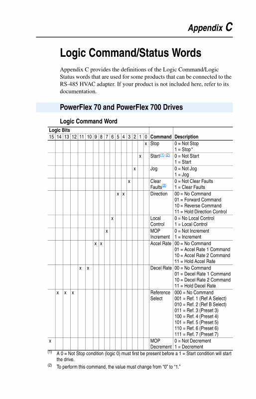
Appendix C
Logic Command/Status WordsAppendix C provides the definitions of the Logic Command/Logic Status words that are used for some products that can be connected to the RS-485 HVAC adapter. If your product is not included here, refer to its documentation.
Logic Command Word
PowerFlex 70 and PowerFlex 700 Drives
Logic Bits15 14 13 12 11 10 9 8 7 6 5 4 3 2 1 0 Command Description
x Stop 0 = Not Stop1 = Stop*
x Start(1) (2) 0 = Not Start1 = Start
x Jog 0 = Not Jog1 = Jog
x Clear Faults(2)
0 = Not Clear Faults1 = Clear Faults
x x Direction 00 = No Command01 = Forward Command10 = Reverse Command11 = Hold Direction Control
x Local Control
0 = No Local Control1 = Local Control
x MOP Increment
0 = Not Increment1 = Increment
x x Accel Rate 00 = No Command01 = Accel Rate 1 Command10 = Accel Rate 2 Command11 = Hold Accel Rate
x x Decel Rate 00 = No Command01 = Decel Rate 1 Command10 = Decel Rate 2 Command11 = Hold Decel Rate
x x x Reference Select
000 = No Command001 = Ref. 1 (Ref A Select)010 = Ref. 2 (Ref B Select)011 = Ref. 3 (Preset 3)100 = Ref. 4 (Preset 4)101 = Ref. 5 (Preset 5)110 = Ref. 6 (Preset 6)111 = Ref. 7 (Preset 7)
x MOP Decrement
0 = Not Decrement1 = Decrement
(1) A 0 = Not Stop condition (logic 0) must first be present before a 1 = Start condition will start the drive.
(2) To perform this command, the value must change from “0” to “1.”

C-2 Logic Command/Status Words
Logic Status Word
PowerFlex 70 and PowerFlex 700 Drives
Logic Bits15 14 13 12 11 10 9 8 7 6 5 4 3 2 1 0 Status Description
x Ready 0 = Not Ready1 = Ready
x Active 0 = Not Running1 = Running
x Command Direction
0 = Reverse1 = Forward
x Actual Direction
0 = Reverse1 = Forward
x Accel 0 = Not Accelerating1 = Accelerating
x Decel 0 = Not Decelerating1 = Decelerating
x Alarm 0 = No Alarm1 = Alarm
x Fault 0 = No Fault1 = Fault
x At Speed 0 = Not At Reference1 = At Reference
x x x Local Control
000 = Port 0 (TB)001 = Port 1010 = Port 2011 = Port 3100 = Port 4101 = Port 5110 = Port 6111 = No Local
x x x x Reference 0000 = Ref A Auto0001 = Ref B Auto0010 = Preset 2 Auto0011 = Preset 3 Auto0100 = Preset 4 Auto0101 = Preset 5 Auto0110 = Preset 6 Auto0111 = Preset 7 Auto1000 = Term Blk Manual1001 = DPI 1 Manual1010 = DPI 2 Manual1011 = DPI 3 Manual1100 = DPI 4 Manual1101 = DPI 5 Manual1110 = DPI 6 Manual1111 = Jog Ref

Glossary
B Bus OffA condition that occurs when an abnormal rate of errors is detected in a device. The bus off device cannot receive or transmit messages on the network. This condition is often caused by corruption of the network data signals due to noise or data rate mismatch.
C ControllerA solid-state control system that has a user-programmable memory for storage of instructions to implement specific functions such as I/O control, logic, timing, counting, report generation, communication, arithmetic, and data file manipulation. A controller consists of a central processor, input/output interface, and memory. Also called programmable logic controller (PLC). See also scanner.
D Data RateThe speed at which data is transferred on the network. Each device on a network must be set for the same data rate.
Datalink
A type of pointer used by some drives to transfer data to and from the controller. Datalinks allow specified parameter value(s) to be accessed or changed without using Explicit Messages. When enabled, each Datalink consumes either four bytes or eight bytes in both the input and output image table of the controller. The drive determines the size of Datalinks.
DPIA peripheral communication interface used by various Rockwell Automation drives and power products.
DPI PeripheralA device that provides an interface between DPI and a network or user. Peripheral devices are also referred to as “adapters” and “modules.” The PowerFlex HIM is an example of a DPI peripheral.
DPI ProductA device that uses the DPI communications interface to communicate with one or more peripheral devices. For example, a motor drive such as a PowerFlex drive is a DPI product. In this manual, a DPI product is also referred to as “product” or “host.”

G-2 Glossary
DriveExplorer Software
DriveExplorer software is a tool for monitoring and configuring Allen-Bradley products and adapters. It can be run on computers running Microsoft Windows 95, Windows 98, Windows ME, Windows NT (version 4.0 or higher), Windows 2000, and Windows CE (version 2.01 or higher) operating systems. DriveExplorer (version 2.01 or higher) can be used to configure this adapter and PowerFlex drives. Information about DriveExplorer software and a free lite version can be accessed at http://www.ab.com/drives/driveexplorer.
DriveTools 2000 SoftwareA software suite designed for Microsoft Windows 98, Windows ME and Windows NT (4.0 or higher) and Windows 2000 operating systems. This software suite will provide a family of tools that you can use to program, monitor, control, troubleshoot, and maintain Allen-Bradley products. DriveExecutive (version 1.01 or higher) can be used with PowerFlex drives. Information about DriveTools 2000 can be accessed at http://www.ab.com/drives/drivetools_2000.
E Explicit Messaging
Explicit Messages are used to configure, monitor, and diagnose devices over the network.
F Fault ActionDetermines how the adapter and connected product act when a communications fault occurs (for example, a cable is disconnected).
Fault Configuration
When communications are disrupted (for example, a cable is disconnected), the adapter and drive can respond with a user-defined fault configuration. The user sets the data that is sent to the drive in the fault configuration parameters: Parameters 18 - [Flt Cfg Logic] through 27 - [Flt Cfg D2 In]. When a fault action parameter is set to use the fault configuration and a fault occurs, the data from these parameters is sent as the Command Logic, Reference, and/or Datalink(s).
Flash UpdateThe process of updating firmware in the adapter. The adapter can be flash updated using the X-Modem protocol and a serial converter.
H Hold Last
When communications are disrupted (for example, a cable is disconnected), the adapter and drive can respond by holding last. Hold
Glossary G-3
last results in the drive receiving the last data received via the network connection before the disruption. If the drive was running and using the reference from the adapter, it will continue to run at the same reference.
Human Interface Module (HIM)A device that can be used to configure and control a drive.
I I/O DataI/O data, sometimes called “implicit messages” or “input/output,” transmit time-critical data such as a Logic Command and Reference. The terms “input” and “output” are defined from the scanner’s point of view. Output is transmitted by the scanner and consumed by the adapter. Input is transmitted by the adapter and consumed by the scanner.
L Logic Command/StatusThe Logic Command is used to control the drive (e.g., start, stop, direction). It consists of one 16-bit word of input to the adapter from the network. The definitions of the bits in this word depend on the drive.
The Logic Status is used to monitor the drive (for example, operating state, motor direction). It consists of one 16-bit word of output from the adapter to the network. The definitions of the bits in this word depend on the drive.
N Node AddressEach device on a network must have a unique node address to identify it. On Modbus RTU, Metasys N2, and Siemens Building Technologies P1 networks, devices can have node addresses between 1 and 255 if the network is set up to accommodate that number of devices.
Non-Volatile Storage (NVS)
The permanent memory of a device. Devices such as the adapter and drive store parameters and other information in NVS so that they are not lost when the device loses power. NVS is sometimes called “EEPROM.”
P Parity Check
When the adapter uses a parity check, a non-data bit is added to each binary word that it sends and receives. Devices on the network verify the data integrity of the transmitted data by checking that the sum of the number of ones in a word is always even or odd.
G-4 Glossary
Ping
A message that is sent by a DPI product to its peripheral devices. They use the ping to gather data about the product, including whether it can receive messages and whether they can log in for control.
R Reference/Feedback
The Reference is used to send a reference (for example, speed, frequency, torque) to the product. It consists of one word of input to the adapter from the network. The size of the word (either a 16-bit word or 32-bit word) is determined by the drive.
The Feedback is used to monitor the speed of a product. It consists of one word of output from the adapter to the network. The size of the word (either a 16-bit word or 32-bit word) is determined by the drive.
S ScannerA scanner is a separate module (of a multi-module controller) or a built-in component (of a single-module controller) that provides communication with adapters connected to a network. See also Controller.
Status IndicatorsLEDs that are used to report the status of the adapter, network, and drive. They are on the adapter and can be viewed on the front cover of the drive when the drive is powered.
T Type 0/Type 1/Type 2 ControlWhen transmitting I/O, the adapter can use different types of messages for control. The Type 0, Type 1, and Type 2 events help Rockwell Automation personnel identify the type of messages that is used.
Z Zero DataWhen communications are disrupted (for example, a cable is disconnected), the adapter and drive can respond with zero data. Zero data results in the drive receiving zero as values for command data. If the drive was running and using the reference from the adapter, it will stay running but at zero reference.

Index
Aadapter
applying power, 2-6commissioning, 2-1compatible products, 1-2components, 1-1configuring I/O for, 3-4connecting to a drive, 2-4connecting to a network, 2-3features, 1-2grounding, 2-5installation, 2-1–2-6mounting on a drive, 2-5parameters, B-1–B-5resetting, 3-8specifications, A-1viewing its configuration, 3-8
applying power to the adapter, 2-6
attentions, 1-3
Bbaud rate, see data rate
bit definitions for logic command/status word, C-1
bus off, G-1
Ccable, 2-4
cablesInternal Interface cables, 2-4required for installation, 1-3RS-485, 2-3
Clear Counters parameter, B-4
Comm Flt Action parameter, B-3
commissioning an adapter, 2-1
compatible products, 1-2
components of adapter, 1-1
configuration tools, 3-1
configuring parameters, 3-1–3-9
connecting an adapter to a drive, 2-4
connecting an adapter to a network, 2-3
controller, definition, G-1
Ddata rate
definition, G-1setting, 3-3
data transfersadvanced (all protocols), 7-1–7-8Metasys N2, 5-1–5-10Modbus RTU, 4-1–4-10Siemens Building Technologies P1,
6-1–6-12
Datalink Size parameter, B-3
Datalinksdefinition, G-1Metasys N2, 7-6Modbus RTU, 7-3–7-5Siemens Building Technologies P1,
7-7–7-8using with all protocols, 7-1–7-8
diagnostic itemslist of, 8-6viewing and clearing, 8-5
dimensions, A-2
DPIadapter uses, 1-2definition, G-1peripheral, G-1ports on adapter and drives, 2-4products, 1-2, G-1
DPI Data Rate parameter, B-1
DPI I/O Act parameter, B-4
DPI I/O Cfg parameter, B-3
DPI Port parameter, B-1
drive, see DPI products
DriveExploreraccessing parameters with, 3-1definition, G-2free lite version, G-2
DriveTools 2000accessing parameters with, 3-1definition, G-2
EEEPROM, see Non-Volatile Storage
(NVS)
I-2 Index
electrical specifications, A-1
environmental specifications, A-2
equipment, 1-3
eventslist of, 8-9viewing and clearing, 8-8
Explicit Messaging, G-2
Ffactory-default settings, 3-8
fault actionconfiguring an adapter for, 3-6definition, G-2
fault configurationconfiguring an adapter for, 3-7definition, G-2
features of the adapter, 1-2
firmware release, P-2
flash update, G-2
Flt Cfg A1 - D2 In parameters, B-4
Flt Cfg Logic parameter, B-4
Flt Cfg Ref parameter, B-4
Ggrounding an adapter, 2-5
HHIM (Human Interface Module)
accessing parameters with, 3-1definition, G-3LCD model, 3-2LED model, 3-2
hold lastconfiguring an adapter for, 3-7definition, G-2
II/O
configuring an adapter for, 3-4definition, G-3
installationapplying power to the adapter, 2-6connecting to the drive, 2-4connecting to the network, 2-3preparing for, 2-1
Internal Interface cablesconnecting to adapter and drive, 2-4shipped with adapter, 1-3
LLCD HIM, 3-2
LED HIM, 3-2
logic command/statusbit definitions, C-1definition, G-3on Metasys N2, 5-4, 5-6on Modbus RTU, 4-6, 4-7on Siemens Building Technologies P1,
6-7
Mmanual
conventions, P-1related documentation, P-1
mechanical dimensions, A-2
Metasys N2data transfers, 5-1–5-10Datalinks, 7-6point map, 5-3–5-6selecting with a switch, 2-2specifications, A-1
MOD status indicatorlocating, 8-1troubleshooting with, 8-3
Modbus RTUdata transfers, 4-1–4-10Datalinks, 7-3–7-5point map, 4-3–4-10selecting with a switch, 2-2specifications, A-1
modes of operation, 1-6
mounting an adapter on a drive, 2-5
NN2 Ref Scale parameter, B-5

Index I-3
NET A status indicatorlocating, 8-1troubleshooting with, 8-4
Net Addr Act parameter, B-1
Net Addr Cfg parameter, B-1
NET B status indicatorlocating, 8-1troubleshooting with, 8-4
Net Chksum Type parameter, B-2
Net Parity Act parameter, B-2
Net Parity Cfg parameter, B-2
Net Rate Act parameter, B-1
Net Rate Cfg parameter, B-1
Net Stop Bits parameter, B-2
network protocolsMetasys N2, 5-1Modbus RTU, 4-1selecting with a switch, 2-2Siemens Building Technologies P1,
6-1
Network Timeout parameter, B-2
node addressdefinition, G-3setting with a parameter, 3-3setting with switches, 2-2
Non-Volatile Storage (NVS)accessing parameters in, 3-1definition, G-3
Pparameters
accessing, 3-1configuring, 3-1–3-9factory-default settings, 3-8list of, B-1–B-5
paritydefinition, G-3setting, 3-4
ping, G-4
plug for cable, 2-3
point mapMetasys N2, 5-3–5-6Modbus RTU, 4-3–4-10Siemens Building Technologies P1,
6-3
PORT status indicatorlocating, 8-1troubleshooting with, 8-2
power consumption, A-1
PowerFlex drives70/700 Logic Command/Status, C-1compatible with adapter, 1-2
preparing for installation, 2-1
processor, see controller
products, see DPI products
programmable logic controller, see controller
Qquick start, 1-5
RRef/Fdbk Size parameter, B-3
reference/feedback, definition, G-4
regulatory compliance, A-2
related documentation, P-1
required equipment, 1-3
Reset Module parameter, B-3
resetting an adapter, 3-8
RS-485 cablesconnecting to 6-pin plug, 2-3selecting, 1-3
Ssafety precautions, 1-3
scanner, G-4
Siemens Building Technologies P1data transfers, 6-1–6-12Datalinks, 7-7–7-8selecting with a switch, 2-2specifications, A-1
six-pin linear plug, 2-3
specifications for adapter, A-1

I-4 Index
status indicatorsdefinition, G-4MOD, 8-3NET A, 8-4NET B, 8-4normal operation, 1-6PORT, 8-2troubleshooting with, 8-1
switchesnetwork protocol, 2-2node address, 2-2
Ttechnical support, P-2
tools, 1-3
troubleshooting, 8-1
Uupdate, see flash update
Vviewing adapter configuration, 3-8
WWeb page
for DriveExplorer software, G-2for DriveTools 2000 software, G-2for manuals, P-1
Zzero data
configuring an adapter for, 3-7definition, G-4

Allen-Bradley, ControlFLASH, DPI, DriveExplorer, DriveTools 2000, DriveExecutive, PowerFlex, and SCANport are trademarks of Rockwell Automation.
Metasys is a trademark of Johnson Controls, Inc.
Modbus is a trademark of Schneider Automation.
P1 is a trademark of Siemens Building Technologies.
Windows, Windows NT, and Microsoft are trademarks of Microsoft Corporation.

www.rockwellautomation.com
Corporate HeadquartersRockwell Automation, 777 East Wisconsin Avenue, Suite 1400, Milwaukee, WI, 53202-5302 USA, Tel: (1) 414.212.5200, Fax: (1) 414.212.5201
Headquarters for Allen-Bradley Products, Rockwell Software Products and Global Manufacturing SolutionsAmericas: Rockwell Automation, 1201 South Second Street, Milwaukee, WI 53204-2496 USA, Tel: (1) 414.382.2000, Fax: (1) 414.382.4444Europe/Middle East/Africa: Rockwell Automation SA/NV, Vorstlaan/Boulevard du Souverain 36, 1170 Brussels, Belgium, Tel: (32) 2 663 0600, Fax: (32) 2 663 0640Asia Pacific: Rockwell Automation, 27/F Citicorp Centre, 18 Whitfield Road, Causeway Bay, Hong Kong, Tel: (852) 2887 4788, Fax: (852) 2508 1846
Headquarters for Dodge and Reliance Electric ProductsAmericas: Rockwell Automation, 6040 Ponders Court, Greenville, SC 29615-4617 USA, Tel: (1) 864.297.4800, Fax: (1) 864.281.2433Europe/Middle East/Africa: Rockwell Automation, Brühlstraße 22, D-74834 Elztal-Dallau, Germany, Tel: (49) 6261 9410, Fax: (49) 6261 17741Asia Pacific: Rockwell Automation, 55 Newton Road, #11-01/02 Revenue House, Singapore 307987, Tel: (65) 6356-9077, Fax: (65) 6356-9011
U.S. Allen-Bradley Drives Technical SupportTel: (1) 262.512.8176, Fax: (1) 262.512.2222, Email: [email protected], Online: www.ab.com/support/abdrives
Publication 20COMM-UM009B-EN-P – January, 2003 P/N 306693-P02Copyright © 2003 Rockwell Automation, Inc. All rights reserved. Printed in USA.