rpt ip sur capella l - geologyontario.mndmf.gov.on.ca file- li - figure or ei c drawing no. title 6...
TRANSCRIPT

l l l l l l l l l l l l l l l l l l l
S3BMNEe015 Z . 1 8696 KEEYASK LAKE
REPORT ON
INDUCED POLARIZATION SURVEY
CAPELLA LAKE, PATRICIA MINING DIVISION
ONTARIO
for
AGNICO-EAGLES MINES LTD.
RtCMVED
IAMUS SfCllOH
Frank L. Jagodits, P. Eng.,
Consulting Geophysicist
October 1987
010
BXGALIBUR INTERNATIONAL CONSULTANTS LTD.


1111111111111111111
* iiiuinniiiiiiiiniii^F 53BMNEeei5 2.18696 KEEYASK LAKE
- i -
TABLE OF CONTENTS
1. Introduction
2. Survey Specifications and Instrumentation3. Presentation of the Data
4. Discussion of the Results
4.1 General Comments
5. Conclusions and Recommendations
6,. References
7. Appendix
- List of Personnel
- Writers Declaration
LIST OF ACCOMPANYING FIGURES AND MAPS
FIGURE OR
EI C DRAWING NO. TITLE
1 General Location Map
2 Claim Group Location
3 Induced Polarization Survey
Pseudo-Section, Line 7+OOE
4 Induced Polarization SurveyPseudo-Section, Line 18+OOE
5 Induced Polarization Survey
Pseudo-Section, Line 20+OOE
1191010C
Page 1
23
4
4
10
11
12
15
16
SCALE
1 : 2500
1:2500
1:2500
BXGAblBUR INTERNATIONALCONSULTANTS fcTD.

- li -
FIGURE OR
EI C DRAWING NO. TITLE
6 Induced Polarization
Pseudo-Section, Line
7 Induced Polarization
Pseudo-Section, Line
8 Induced Polarization
Pseudo-Section, Line
9 Induced Polarization
Pseudo-Section, Line
10 Induced Polarization
Pseudo-Section, Line
11 Induced PolarizationPseudo-Section, Line
12 Induced Polarization
Pseudo-Section, Line
EIC-1856 Induced PolarizationApparent Chargeabili
-1857 Induced Polarization
Apparent Resistivity
-1858 Induced Polarization
Survey,
22+OOESurvey,23-fOOE
Survey,
24+OOE ;
Survey,
26+OOE
Survey,
28+OOE
Survey,30+OOE
Survey,
32+OOE
Survey,
ty Contours n^l
Survey,
Contours n-1Survey,
SCALE
1:2500
1:2500
1:2500
1:2500
1:2500
1:2500
1:2500
1:5000
1:5000
1:5000Differential SP Contours
-1859 Induced Polarization
Interpretation Map
Survey, 1:5000
BXGAblBUR INTERNATIONAb CONSULTANTS I*TD.

l l l l l l l l l l l l l l l l l l l
1. INTRODUCTION
In the spring of 1987, Agnico-Eagle Mines Ltd. conducted
ground magnetic and VLF-EM surveys over a group of claims east of
Capella Lake, Ontario (Fig. 1). Based on the results of the
above survey, recommendations were made to carry out an induced
polarization/resistivity survey over selected parts of the
claims. The purpose of the surveys was to detect sulphide
mineralization and alteration which may be associated with
precious metal deposits (Ref. 1). '
TechTerrex Inc. of Mississauga carried out the time
domain induced polarization/resistivity survey over parts of the
claims which are located approximately 185 km north of Pickle
Lake, Ont. (N.T.S. Map 53 B/14). The survey took place from July
22nd and to August 10th, 1987 and altogether 6.1 km of lines were
covered. The claim group is shown on Fig. 2.
The lines surveyed are listed below (the corresponding
claim numbers are given in brackets):
Line 7+OOE (1-869359 and 1-869360), Lines 18+OOK and 20+OOE
(1-869264 and 1-869265), Lines 22+OQE, 23+OOE and 24+OOE
(1-869261 and 1-869262), Line 26+OOE (1-869254 and 1-869255),
Lines 28+OOE and 20+OOE (1-869252 and 1-869253) and Line 32+OOE
(1-869244 and 1-869245).
The following report gives the survey specifications,
instrumentation and discusses the survey results.
BXGAMBURINTERNATIONALCONSULTANTS

l lll l l l l l l l l l l l l l l l
CAPELLA LAKE PROJECT AREA
n ,,-.p
' l 'i.'x .-''r'J- '
•- f ., ; j i? s y ' x i ;
-o /'a
GENERAL LOCATION MAP

LCCCNO
CZ1' CD CD
\f—bud'
B3
c^ *cv5 ^V"^^^ -
FIGURE 2
CLAIM GROUP LOCATION
KEEYASK LAKE CLAIM SHEET AHEA
t.** t tO.OOO

- 2 -
2. SURVEY SPECIFICATIONS AND INSTRUMENTATION
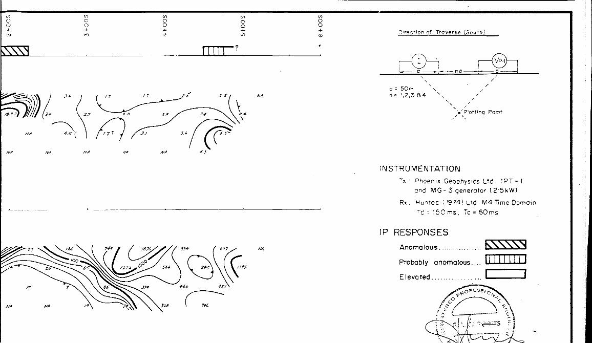
The survey was conducted employing the M4 time domain receiver manufactured by Huntec (1974) Ltd. of Toronto coupled with the 2.5 kW transmitter, IPT-1 and the generator MG-3 which were made by Phoenix Geophysics Ltd. of Markham, Ontario.
The dipole-dipole electrode array was utilized with an electrode separation (a) of 50m. The apparent chargeability and apparent resistivity were determined at dipole separations (n) of 1 to 4. The survey was conducted in such a way that the current electrode dipole was always to the north of the potential dipoles (traversing due south).
The current cycling rate was 2 sec. "on" and 2 sec. "off" and the measurement of the decay of secondary voltage during the "off" period commenced after an initial delay of 150 msec. The M4 receiver is capable of measuring the decay over selectable periods which are divided into ten windows. For this survey a window width of 60 msec was employed and the total apparent
chargeability and the apparent chargeability in the second, fourth, sixth, eighth and tenth windows were recorded in the field note books. In addition, the self-potential (SP) between the potential electrodes were also measured providing profiles of
differential SP.
BXGAbinilR INTERNATIONAL CONSULTANTS IsTD.

l l l l l l l l l l l l l l l l l l l
— 3 —
3. PRESENTATION OF THE RESULTS
The results are presented on pseudo-sections at a horizontal scale of 1:2500. The pseudo-sections show the apparent chargeability observed in the eighth window, the computed apparent resistivity and the metal factor. The sections also show a topographic profile along the line (vertical scale 1cm ^ 25m) and the profile of the differential SP. The differential SP observations are shown in the centre of the potential dipoles. The pseudo-sections (Eigures 3 to 12) are located in the back of this report.
The apparent chargeabilities, apparent resistivities observed at n ^ 1 and the diferential SP are given on stable based copies of the base map provided by Agnico-Eagle Mines Ltd. at a scale of 1:5000. (The same base map was used to present the results of the earlier surveys).
In order to portray possible trends, contours are shown
where possible. The contour interval is 1.0 msec on the apparent chargeability map and on the apparent resistivity : contour map the following contours are shown: 25, 50, 100, 250, 500, 1000, 2500, 5000 and 10,000 ohm-m. The zero, -50mV, -lOOmV and -500mV contours are given on the differential SP map.
The interpretation is presented on stable based copy of the Interpretation Map of Ref. 1 and on the pseudo-sections.
BXGAMBURINTERNATIONALCONSULTANTS

l l l l l l l l l l l l l l l l l l l
- 4 -
4. DISCUSSION OF THE RESULTS
4.1 General Comments
The general geology and the history of previous work is given in some detail in Reference 1. The geology of the claims can be stated briefly as having three major rock types commencing from the north: granite gneiss, mafic volcanics and conglomerate-wacke. In addition, a diabase dyke and mafic intrusives were also mapped.
The previous ground magnetic surveys have clearly outlined three magnetic domains corresponding to the rock types given above. The ground VLF-EM survey have indicated numerous VLF-EM conductors of which the major west-northwest striking conductor describes a regional fault separating the volcanics and sediments.
The induced polarization survey was concentrated in the southeast corner of the property where possible Iron formations were indicated by the magnetics in areas of structural deformation. This area could be near the intersection of two structural breaks, the above mentioned regional fault and a north-northwest striking fault which is now filled by a diabase dyke. Additional lines were also surveyed to test the major fault and its vicinity, and to test the non-magnetic and magnetic volcanics in the west central map area (Line 7+OOE).
BXGAMBUR INTERNATIONAL CONSULTANTS bTD.

l l l l l l l l l l l l l l l l l l l
- 5 -
Unfortunately, the very unusual ground and geological conditions prevented the introduction of sufficient current into ground to produce reliable observations of the apparent chargeability at many localities. These locations are marked with an "NA" on the pseudo-sections and the chargeability map. It is noteworthy that these conditions occurred when the current electrode dipole was located south of the base line. Under normal circumstances quite reliable observations were made at dipole separation n ~ 1 , but the reliability deteriorated at increasing dipole separations. An exception is the area just south of the base l ine on Lines 23+OOE and 24+OOE where reliable observations could not be made even at the first dipole separation. The peculiar conditions may be caused by very high contact resistances at the current electrodes. The survey crew attempted to remedy the situation by moving the current electrodes or watering them, which was successful on occasion. It is also suspected that rapidly varying electrical properties of the overburden and bedrock may have created unusual near surface current paths resulting in the unreliable measurements. It is also noted that the apparent resistivities associated with the "NA" apparent chargeabilities may be less reliable because of the small current applied and because of the small primary
voltages obtained.
The study of the apparent chargeabilities reveals that they seldom deviate markedly from the background. Where the
chargeabilities are about one and one-half times the background they are marked as having "elevated chargeability" which is the lowest,'possible anomalous' rating. The majority of the indicated localities fall in this category. In addition one
BXGAfclBUR INTERNATIONAb CONSULTANTS IsTD.

l l l l l l l l l l l l l l l l l l l
- 6 -
location was identified as probably anomalous and one locality as anomalous.
The contour map of the apparent resistivity at n ^ 1 was used to indicate the areas where the apparent resistivity is less than 100 ohm-m. Not surprisingly, these areas appear to correlate with zones of structural deformation indicated by VLF-EM conductors (conductive faults and/or shears) and by structures interpreted from the magnetic contour map.
The differential SP anomaly axes which are graded weak,
moderate and strong were taken from the contour map and will be discussed below as appropriate.
The surveyed part of Line 7+OOE crosses the extreme
northwest, narrow end of a magnetic volcanic unit which is in contact with interpreted altered non-rnagnetic volcanics. This
part of the line is north of the base line and measurement problems were not encountered. Elevated chargeability coupled with medium to high resistivities were observed over the narrow, magnetic volcanics. It would appear that higher resistivity
rocks could underlay the area of interpreted altered volcanics. Further work will be needed to confirm this observation. The IP anomaly may have been caused by rock type change. The northerly SP anomaly correlates with a zone of lower resistivity; however
there are insufficient data to predict a source reliably.
The observations along Line 18+OOE contain many "NA" situations at n ^ 2, 3 and 4. One zone of elevated chargeability just south of 4-fOOS is outlined near the interpreted boundary
BXGALIBUR INTERNATIONAL CONSULTANTS LTD.

l l l l l l l l l l l l l l l l l l l
- 7 -
between two volcanic units. It is associated with a relative resistivity low. The main low resistivity feature of the line is found at the southern end where the major west-northwest striking fault zone intersects an interpreted northwest shear; the n^l apparent chargeabilities are at background. Unfortunately, reliable chargeabilities could not be obtained at the larger dipole separations, hence any mineralization which may be associated with the major structure was not detected. Only minor, weak differential SP anomalies were observed at this location, but the pronounced resistivity low describes the structurally disturbed zone.
The induced polarization data include many "NA" stations along Line 20+OOE, The questionable elevated chargeability feature near 2+OOS is over a magnetic anomaly and a VLF-EM conductor (VC 3). The chargeability anomaly is associated with a moderate differential SP anomaly and a relative resistivity low. Once again rock type change and/or very minor mineralization along a fault and/or contact may be implied. \
The induced polarization results are indeed poor along Lines 22+OOE, 23+OOE and 24+OOE. Only one questionable, elevated chargeability was outlined on Line 24+OOE north of the base line,
correlating with a magnetic anomaly at the contact between members of the volcanic domain. There is no further interest attached to this anomaly. The interesting feature of this area is a zone of very low apparent resistivity covering three VLF-EM
conductors and a part of a magnetic anomaly. This zone also covers two significant differential SP anomalies. It is noted that northern SP anomaly appears to be on an upward sloping
BXGAbiniJR INTERNATIONAL CONSULTANTS bTD.

l l l l l l l l l l l l l l l l l l l
- 8 -
ground. The source of the SP responses is enigmatic, but both anomalies are near VLF-EM conductors. The zone of low apparent resistivity could indicate an intensely fractured area which may be covered by conductive overburden. However it should be kept in mind that the apparent resistivities coupled with the "NA" chargeabilities are suspect.
Although the number of "NA" observations have decreased along L-26+OOE the results are essentially featureless. The very high resistivities observed at 2+25S and at the corresponding larger dipole separations are due to conditions at the site of the current electrode pair (located at H-50S and 2+OOS). An elevated chargeability anomaly centred about 5+OOS is the noted event of L-28+OOE. It is associated with a -623mV differential SP anomaly and a relative apparent resistivity low. The possible anomaly is located at the interpreted boundary between sediments and volcanics and it correlates with VLF-EM conductor VC6. It is suggested that above signatures could indicate sulphides and/or
graphite.
The prime event of the survey occurs on L-30+OOE centred
about 1+75S. The 18.7 msec observation at 2+OOS, n ^ 2 is
questionable, however there is an anomalous build-up at dipole separations of n ~ l and n ^ 2. The IP anomaly which could indicate sulphides is associated with moderate to low apparent
resistivities in an area interpreted to be underlain by moderately magnetized volcanics. The anomalous situation is near a nearly circular magnetic anomaly, believed to indicate mafic rocks which may be part of the diabase dyke observed further to the north-northwest; as noted earlier this diabase dyke may
BXGAMBUR INTERNATIONAL CONSULTANTS bTD.

l l l l l l l l l l l l l l l l l l l
- 9 -
signify the location of another significant zone of weakness.
This IP anomaly is just north of a magnetic event which may indicate iron formation.
The northerly elevated chargeability anomaly of L-32+OOE is manifested at n ~ 1 and it could be considered as the signature of the eastesrly continuation of the anomalous horizon on L-30+OOE. However the magnetic association which exists on Line 32+OOE is lacking on L-30+OOE, consequently the possibility of having two separate sources should be kept in mind.
The probable IP anomaly at the southern end of L-30+OOE and the southern elevated chargeability of L-32+OOE form a weak east-northeast trend which is associated with a mangetic unit
indicating possible iron formations. The IP trend and the IP anomalies are also associated with an east-northeast striking shear zone. The probable IP anomaly of L-30+OOE, which is open to the south is situated over the intersection of the above mentioned shear and an interpreted shear striking northwest. The southern elevated chargeability of L-32+OOE appears to have deeper source which may be nearer to surface at 3+OOS. Although the IP responses of this trend are not well defined, the trend occupies a significant location near possible iron formation in an area of complex structural deformation. It is believed that the cause of the IP responses include sulphide and magnetic sulphides which may be located along a shear zone.
HXGAMIUW INTERNATIONAL CONSULTANTS LTD.

l l l l l l l l l l l l l l l l l l l
- TO -
5. CONCLUSIONS AND RECOMMENDATIONS
The effectiveness of the limited induced polarization coverage was considerably reduced by the unususal electrical property variations in the overburden and bedrock south of the base line. These variations could have caused the conditions in which the observations became unreliable. These are marked as "NA" on the pseudo-sections and on the apparent chargeability contour map.
The observations at n ^ 1 indicate that the chargeability remains moderately uniform near surface. Several elevated (about 1.5 times background) IP responses were observed together with an anomalous xone on L-30+OOE which possibly extends to L~32-fOOE. The anomaly which could indicate sulphides could constitute a drill target if the locality is believed to be geologically favourable. The other locations of further interest are found along the east-northeast trending weak IP trend commencing at about 4+65S on Line 30+OOE. This trend appears to correlate with a magnetic unit which may represent iron formation and/or basic volcanics and it is also associated with an east-northeast interpreted shear zone. Sulphides, magnetic sulphides associated with the iron formation could be the source of the IP responses.
Although the elevated IP feature at 5+OOS, on Line 28+OOE is outside, but very close to the above mentioned magnetic unit it gains importance because of its location along the interpreted boundary between volcanics and metasediments and because of the
EXGAblBURINTERNATIONALCONSULTANTS

l l l l l l l l l l l l l l l l l l l
- 11 -
correlation between the IP feature and a strong differential SP anomaly, indicating a weakly mineralized contact and/or shear zone.
An area of very low apparent resistivity coupled with differential SP anomalies located just south of the base line between Lines 22-fOOE and 24+OOE could also hold further interest.
The present induced polarization survey provided only partial results which should be combined with the more recent geologic information to select drill hole locations.' The promising, partial IP results show weak trends, indicating possible line-to-line correlation which suggest that the re-surveying the original recommended areas employing special surveying techniques would be beneficial to outline zones of weak mineralization. It is recommended that the new surveying should employ a 7.5 kW or 10 kW transmitter. It is believed that use of the gradient array will help to overcome the problems encountered during the present survey. However, it is suggested that as an alternative, the PPL (lateral pole-pole) array should also be tested. The specifications for the survey and the test could be prepared after reviewing the present results in the light of new geologic information. The specifications should be flexible to allow the operator to change current electrode locations to avoid high contact resistances, realizing that some experimentation will be needed to locate the proper current electrode sites. It is also recommended that the VLF-EM surveying of the claims should be completed if a crew is mobililzed to conduct the new IP surveys.
BXGftblBUR INTERNATIONAb CONSULTANTS IsTD.

l l l l l l l l l l l l l l l l l l l
- 12 -
In view of the difficulties of the present IP survey, it is recommended that a geophysicist should be present during the initial part of the new survey.
FraVik u.
Consulting Gooo ph y gio i s t-/.'''
BXGAMBUR INTBRNATIONftl* GONSUbTANTS bTD.

l l l l l l l l l l l l l l l l l l l
- 13 -
6. REFERENCES
1. Jagodits, F.L., 1987 Report on Ground Magnetic and VLF-EM Surveys, Capella Lake, Patricia Mining Division, Ontario, prepared for Agnico- Eagle Mines Ltd.
EXGAMBUR INTERNATIONAL CONSULTANTS LTD.

1111111111111111111
0- 14 -
7. APPENDIX
LIST OF PERSONNEL
Name
———
J. Ashenhurst, Operator
M. Nemes, Helper
P. Perigny, Helper
0. Adeniji, Helper
R. T. Marcroft, Drafting
Address
13771 - 114A Ave.
Surrey, B.C.
V3R 2N3
102 - 770E 7th Ave.
Vancouver, B.C.
V5T 1P2
321 Oakwood Ave.
North Bay, Ont.
P1B 9C6
1201-200 Woolner Ave.
Toronto, Ont.
M6N 1Y4
10 Hurontario Street,
Mississauga, Ont.
L5G 3G7.
BXGAblBUR INTERNATIONAL CONSULTANTS fcTD.

l l l l l l l l l l l l l l l l l l l
- 15 -
S. Blunt, Typing
F.L. Jagodits, P. Eng.
Consulting Geophysicist
10 Hurontario Street,
Mississauga, Ont.
L5G 3G7.
353 Berkeley Street,
Toronto, Ont.
M5A 2X6.
BXGAMBUR INTERNATIONAL. CONSULTANTS I*TD.

l l l l l l l l l l l l l l l l l l l
- 16 -
CERTIFICATE
I, Francis Loui Jagodits, of the City of Toronto, County of York,
Province of Ontario, do hereby certify that:
1. I am a geophysical engineer residing at 353 Berkely Street, Toronto, Ontario.
2. I am a graduate of the Technical University of Sopron, Hungary with a Dipl. Eng. degree in geophysical engineering (1956).
3. I am a member of the Society of ExplorationGeophysicists, the European Association of Exploration Geophysicists, the Canadian Geophysical Union and a Fellow of the Geological Association of Canada.
4. I am a professional engineer, registered in the Province of Ontario.
5. I have no direct or indirect interest, nor do I expect to receive any interest directly or indirectly in the property or securities of Agnico-Eagle Mines Ltd.
6. The statements made in this report are based on the study of published and unpublished private reports.
7. Permission is granted to use in whole or in part forassessment and qualifications requirements but not for advertising purposes.
Dated at Toronto,This 8th day of October, 1987
Francis L. Jagodi\*Si XDipl-^Eng. P. Eng.X 1 B^prfBlBUR
*1 ffi.-INTERNATIONAL-INTERNATIONAL CONSULTANTS LTD.

l l l l l l l l l l l l
o o
CHARGEABILITY :i ^ ''''vo" - seconds ,
volt
5 "Vs/V ' m Vs/V
- 3
RESISTIVITY.
Lcgc"*'1rT"c cci*ou r | ri
"V. 'C a- -n e'c
~- _ '-5,3,5,7 -5 n-m e'C-
o •e
o o
/•f 1.1,
/•e
Z.ff 2-0?
/f//J

o o
2.2
CD
(S)o
Direc*'6n of Trove^se (South)
o r 50m \ i- 1,2,3 S4
' 'P'ottjng Point
INSTRUMENTATION
Tx : phoenix Geophysics Ltd IPT-1 and MG-3 generator (2-SkW)
Rx: Huntec (!974) L*d V4 Time Domain
Td ^ !50ms, Tc = 60ms
IP RESPONSE
Anomalous,,.
Probably anomalous.... L-.-.-.J
Eleva
\

co o0 J--o
COo oJ.^-
1
COoO-i- in
——J
CO0 O-1-U3
CO Oo^N-
Zof
2/5"
M* 3 l ? 3.*?
of Troverse (South)
o ——
O - 50m n- !,2,3
'.'Plotting Point
INSTRUMENTATIONTx : phoenix Geop.hysics Ltd (PT- i
and MG-3 generator (2-5KW)
Rx: Huntec (1974) Ltd M4 ^me Domain Td = iSCms, Tc = 50ms
IP RESPONSE
Anomalous...
Probably anomalous...... L
Elevated.................... L

l l l l l l l l l l l l
CHARGEABILITY : IV!sf rri'M'vo" - seconds ^
volt
Con'Diir intorvo's:
S^. Sr-Vs/V
x., l m VS/V
co C O4-
CO (^OO-ex1
CO r^
C -1-•o
CO 0oJ-^
1
COoO-um
1
CO O 0-J-
u?
APPARENT RESISTIVITY:- m e'res )
i*^'ri | c coi*ou r ii'e 0 n- -ri e*c. -5,3,5,7-5 H-m e*c.
z i
/. 7 Z y
3. f 3.1?

l l l l l l l l l l l l
C U ARGEAB!UTY-n.i', vo "- - seconds ,
CO n *OUr in'eryg' 5 ;
S^. 5 ^vs 7 V x^. ' "-Ws /v
APPARENT RESISTIVITY:
Lcoc r !*h-Yi'c cc^'ou'' | ri **"S. 'O H. - m e*c.
•*— 1-5,3,5,7-5 firn e'c.
oo Oo
o o
toCo O
CO
O O -i-(O
l i
J. o 7
12.-J
2.S-
J. f
' 3 l 3.0?

to O O
CO Oo
COo o
tOo o
Direc*'on of Traverse ( Sou^h)
/•t
f f,
3 l
Z V 2 t,
——— 3"
'S./
3-3
3.0 7
a - 5 0m i- 1,2,3
Point
INSTRUMENTATIONTx : Phoenix Geophysics Ltd IPT-1
ond MG-3 generotor (2-5kW)
Rn: Huntec U974) L*d M4 "Hme Domain Td - 150ms, Tc = 50ms
IP RESPONSE
Anomalous..
Probably anomalous.... LI
Elevated. ........,....... L-

o(f) o o o
oDirection of Troverse (Sou^b)
2-7a - 50m n^ 1,2,3
'•'p'otting Poirits 3
INSTRUMENTATIONTx : Phoe n ix Geophysics Ltd IPT-1
and MG -3 generator (2'5kW)
Rx: Huntec (1974) L*d M4Time Domain Td ^ 150 ms, Tc - 60ms
IP RESPONSE
Anomalous..
Probably anomalous.... L
Elevated................... L

l l l l l l l l l l l l
CHARGEABILITY : V!smi ! l 'vo" - seconds ,
voi* "~~ '
5 nWs /V l m Vs/V
APPARENT RESISTIVITY:
ooo r i*hTt'c contour tn*
. 10 fi- m e*c
— '-5, 3, 5 , 7- 5 rim etc-
n ^ 2
O O
en O O
en O O
z-7
2.4
COO O

l l l l l l l l l l l l
CHARGEABILITY : Ms( -rv " i v o'* - seconds ,~ "
5 riVs /V
l mVS/V
APPARENT RESISTIVITY( O^TI - metres )
Q H- rri e*C.
'-5.3,5,7-5n-m etc.
n : 2
/-J
/•S 7
COo o
CD
OO
f.7
Z 07
Zz-JS
viO O

tn O O
CDo o
w o o
Direction of Traverse (South)
2-4?
0 ~H —
-^h, — __ o ___ *-L-- ~ - - n a
\N
50m N',2,3 8-1 \
——— (V^-i) ——
s/
/s
s
".'P'otting Point
8-7
INSTRUMENTATIONTX : Phoenix Geophysics Ltd IPT- l
and MG-3 generator (2-5kW)
Rx: Huntec (1974) Ltd M4 Time Domain Td - 1 50ms, Tc z 60ms
P RESPONSE
Anomalous ..
Probably anomalous..... L
Elevated................... l

COcO
O O
c o
girec*'OP of Troverse (South)
If 7
O ; 50mn^ 1,2,3
Point
INSTRUMENTATIONTx : Dhoenix GeoDhysics Ltd !PT-
and MG-3 generoTor (2-5KW)
U974) Lrd M4 Tlme Domain ""d ^ 150ms, Tc - 60ms
IP RESPONSE
Anomalous................. I\\XX\\1
Probably anomalous .... L J---- — J
Elevated................... l —J

SOC
H
SOO
4
SO
CH
NG
CH
o-.COs-Ij fS
8
Cj
t/*U
J '
liJ E
C
C C
C
IftOk.
1 v -^ ^
•* i/)
vi
1 E
Ec
•n -
O
1 J
oQ.
JZ CO00LJcr~-^
LiJor.Q
. Q,
k.Eer: O
C
C f
C
y."bE o
^ O
)
g E
r C
i o
-
' M
0
"' N
c E
in
f
C!
"l
E
0
9CJ'
-oil

oO O
Oo
V)oo
V)o o?irec t 'Qp of Troverse (South)
/••s x 3
2. r
INSTRUMENTATIONTX : Dhoenix Geophysics Ltd !PT- 1
ond MG- 3 generator ( 2'5kW)
RK: Huntec (1974) L^d M4 Time Domain Td ^ 150ms, Tc = 60ms
IP RESPONSE
Anomalous...
Probably anomalous...!
Elevated .............. ....l

SOC
M9
SO
CH
S
SO
CH
SO
CM
9
SGCH
Z
V;
SO
CH
l
•T8
(T C
C
C
O
Q.
1 —CO
—p
x w
h '-
00LO
J
V
S *C
[ IT)
UJ
'
lij- f.
UJ
10 CT
S ^
h-1
c ^ x
UJ
^ ^ cr
1 f-
E g
c w - Q:
Oil
^r
u
—
o y
y -^
*
((
W;
4(bEe~0, _ ,
•J'
4-Cri orC'
Uo
*
OCJOr i^Ti'C
i. 1C Q--
-.j i
c c.
c c
o4-E^ro 10i(

oo o
to oo
wo o
/•S? z./
Z.6
•4726
71*
o o
o* Trcverse (Sou*h)
O -— — t——— no -
o rn- ,2,3 Si
".'P'otting Po'nt
INSTRUMENTATIONTx : Dhoemx Geophysics Ltd !PT- l
and MG-3 generotor (2-5KW)
Rx.: H untec (1974) Ltd W4 Time Domain Td - 150ms, Tcz 50ms
IP RESPONSE
Anomalous...
Protxibly anomalous..... l
Elevated............... l i

l l l l l l l l l l l l
CHARGEABILITY : M s^ -TV^'^'VO"- seconds , ' v o' *
^'our m'e'vo' s :
5 r^Vs /V
i ^ V s /V
APPARENT RESISTIVITY :
ic coi'our in*e'vo's
;o Q i-53
n -- 2
n; 3
co
O
COo o
COo0
CO00
ID
1 1
COOoCO
Z-*
Z-S
A'X -30- 2.1 i-k
CO CO CO CO CO C 0 O o O 0 0 O o O ^ i i * J Direction o' Traverse (Sou*b)
CsNN^ L ; -~-j— —— o ——— i— —— no ———
— (Q —— ——— 0 ————— 1
a : 50m \ n^ 1,2,3 S & \
'.'P'otting Point
INSTRUMENTATIONr* : Phoenix Geophysics Ltd l PT- 1
and MG-3 generator (2-5kW)
Rx: Hu-itec (!974) Ltd M4 Time Domain Td - !50ms, Tc = 60ms
IP RESPONSES
Anomalous.....
Probably anomalous.... l
Elevated

o oCOo o o
COo o
COo o
COo o
CHARGEABILITY :( ^l''''vo" ' seconds ,
volt
Co n 'our i^te-'vo' s :
S.. 5 ^Vs/Vv^ ' m Vs X V
l\\\\\\\\\\Vi
xV/f
APPARENT RESISTIVITY:OHm -
0 n - "i e'c -5,3,5,7-5n-m etc.
n - c. 744.

0o•o
1
CO0 O
1
CO0 0
LO
,
CO0o
,
COo oN'
,
2.3
l2o
3.2.
Pirec* ; on o ' Traverse ( Sou*h)
0 - 50m i^ 1,2,3
Point
INSTRUMENTATIONT* ; Phoenix Geophysics Ltd !PT- l
G"d MG-3 generoTor (2-5KW)
Rx: Huitec (1974) L!d V4 "^me Domain ^d - 150ms, Tc : 60ms
P RESPONSESAnomalous ........
Probably anomalous.
Elevated..............
LIL__J

l l l l l l l l l l l l
"n' : ''VC'* - S'? C Q ^ c! S
Co n *ou r ' n *e r
••^ 5 ^ Vs 7 V
v^ l nn VS/ V
APPARENT RESISTIVITY :
e*c.
n ^ 2
-4-
inO OCM
1 1
tooo
1
too04-
1
en00
IO
enO O
3 t, z. t 3.Z.
3.3
Z.3
l2-0
/i.
/

Ontario
Ministry ofNorthern Developmentand Mines 53BHNEeei5 S . 1 8696 KEEYASK LAKE
Ministere du Developpement du Nord et des Mines
February 8, 1988 Your File: 87-236 Our file: 2.10696
900
Mining RecorderMinistry of Northern Development and MinesCourt HouseP.O. Box 3000Sioux Lookout, OntarioPOV 2TO
Dear Sir:
f u ' .'a' • .'•^iv'ii.:! •it r i..11-' /l , V-'i
f. R l G 1C!W
PI f:- c i -, i v r DRE: Notice of Intent dated January 22, 1988
Geophysical {Induced Polarization) Survey submitted on Mining Claims PA 869244 et al in the Area of Keeyask Lake
The assessment work credits, as listed with the above-mentioned Notice of Intent, have been approved as of the above date.
Please inform the recorded holder of these mining claims and so indicate on your records.
Yours sincerely,
W. R. Cowan, ManagerMining Lands SectionMines and Minerals Division
Whitney Block, Room 6610 Queen's Park Toronto, Ontario M7A 1W3
Telephone: (416) 965-4888
RM:plEnclosure: Technical Assessment Work Credits
cc: Mr. G.H. FergusonMining A Lands Commissioner Toronto, Ontario
Mr. J.B. Boniwell, Mr. S. Medd 10 Hurontario Street Mississauga, Ontario L5G 3G7
Resident Geologist Sioux Lookout, Ontario

Ministry ofNorthern Development
Technical Assessment Work Credits
Ontario Date
Janaury 22, 1988
File2.10696
Mining Recorder's Report of Work W 8? ^ 236
Recorded Holder
J. B. Boni well , S. MeddKXOUWXifr Area
Keeyask LakeType of survey and number of
Assessment days credit per claimGeophysical
Magnetometer Hays
46
Other days
Section 77 (19) See "Mining Claims Assessed" column
Geological days
Geochftmical . days
Man days Q Airborne Q]
Special provision | | Ground (x)
1 l Credits have been reduced because of partial coverage of claims.
fi Credits have been reduced because of corrections to work dates and figures of applicant.
Mining Claims Assessed
PA 869261 869359 to 360. inclusive
Special credits under section 77 (16) for the following mining claims
40 Days Induced PolarizationPA 869244 to 245 inclusive
869252 to 255 inclusive 869262 869264 to 265 inclusive
Mo credits have been allowed for the following mining claims
Q not tuff iciently covered by the survey Q insufficient technical data filed
* Maximum geophysical credits attained on claims PA 869244 to 245 inclusive, 869252 to 255 inclusive, 869262 and 869264 to 265 inclusive under subsection 77(9) of the Mining Act, RSO 1980.
The Mining Recorder may reduce the above credits if necessary in order that the total number of approved assessment day* recorded on each claim does not exceed the maximum allowed as follows: Geophysical -80; Geologocal-40; Geochemical - 40; Section 77(19) -60.
626 (65/12)

Ministry of., N6rthern Development
and MinesOuaoo
Report of Work(Geophysical, Geological, Gcochemical and Expenditures) 8 f-Z St,
Mining Act J
Instructions: — Please type or print.If number of mining claims traversed exceeds soace on this form, attach a list.
Note: — Only days credits ca'culated in the "Expenditures" section may be entered in the "Expend. Days Cr." columns.
— Do not use shaded areas below.Type of Survcy(s)
TT-WTOED POLARIZATIONClaim Holdcrls)
J. B. BONIV ? EJ.3 , S. MEDD
Township or Area
KEEYASK I-AKS/6-2085Prospector's Licence No.
A49270/.M9150Address
10KURONTARIO ST., MISSISSAHOA, ONTARIO J5" 307Survey Company Date of E
TEdHTERREX INC. ?02a y \ rurvey (from e/ to))7 87 i10 OS 87vlo. I Yr. Day l Mo. l Yr.
Name and Address of Author (of Geo-Technical report)
FRANK L. JAGODITS, 10 HURONTARIO ST., MISSISSATCA, ONTARIO I
Total Miles of line Cut
5.2 km
50 307Credits Requested per Each Claim in Columns at right Mining Claims Traversed (List in numerical sequence)Special Provisions
For first survey:
Enter 10 days. (This includes line cutting)
For each additional survey: using the same grid:
Enter 20 days (for each)
RECEM., D.,, JAN J
Complete reverse side and enter 'CHWslilf^ l AU
rf
Airborne Credits
Note: Special provisions credits do not apply to Airborne Surveys.
Geophysical
- Electromagnetic
- Magnetometer
- Radiometric
1- Other
VfO
Geochemical
Geophysical
)S ®TtWnet c- Magnetometer
- Radiometric
- Other -j. ^ p
Geological
Geochemica
Electromagnetic
Magnetometer
Radiometric
Days perClaim
Days per Claim
46
Days per Claim
Expenditures (excludes power stripping)Type o* Work Performed
Performed on Claim(s)
Calc ulation of Expenditure Days Credits
Total Expenditures
S -5- 15
cTotal
Jays Credits
Instructions Total Days Credits may be apportioned at the claim holder's choice. Enter number of days credits per claim selected in columns at right.
D.itc . Recorded HnfUcr c^ec. 16/87 ' farf (' i
rAy tjjgnature)
Mining ClaimPrefix
Pa. v .•.-V'.'.'' -'
* - :' j *
l-
..~
Number
86924/1
86923586925286925386925486925586Q26186Q262869264869265869359869360
x^nTK7'fc nr\\if(ffillV' Oc.C w ^ '*
.-.. Ml
J^DWISIQ.
Expend. Days Cr.
^s."x/
•07 B^lOf
tps
-K
A. eton.!For Office Use Only
T"olal Days Cf Recorded
4?6)
Certification Verifying Report of Workhereby certify that l have a personal
or witnessed same during and/or after
Namo and Postal Address of Person Certi
- i Ciiriol n . V/il son
Date Hccoracd
J)fC. 22, it S fDato Aoproved as Recorded
Mining ClaimPrefix | Number
——
. ————————————
TrffalruTrnb/r of mining clayms covefect-tw this report of work. ^S.
Min/ftg Recori\er f
Branf*i"Director j C. rJ). / ,-Ji 1 J
QfrtSc^ls*^-*-^
Expend. Days Cr.
——————
12
1— VJU~X
nnd intimate knowledge of the fncls set forth in (he Report of Work annexed hereto, having performed the work its completion nnd the annexed report is true.
tying
-..3. Jlo.s.ew.o.o d .^\V.B. , .. F:i ss jpRnnpm Ont.ArJn T^O ~T:n
S&T/^; Ce^fffied bw)Sigoaturef) i /?

Assessment Work Breakdown
Man Days are based on eight (8) hour Technical or Line-cutting days. Technical days include work performed by consultants, draftsmen, etc..
Type of Survey
INDUCED POLARIZATJOr SHRVEY
Technical Days
70 X y
Technical Days Credits
n: 553
Line-cutting Days Total Credits
4- 553
No. of Claims
,| 12 .
Days perClaim
A6
Type of Survey
Technical Days Credits
Lino-cutting Days Total Credits
Days per Claim
X 7
X 7
X 7

Ontario
Ministry ofNorthern Developmentand Mines
Geophysical-Geological-Geochemical Technical Data Statement
TO BE ATTACHED AS AN APPENDIX TO TECHNICAL REPORTFACTS SHOWN HERE NEED NOT BE REPEATED IN REPORT
TECHNICAL REPORT MUST CONTAIN INTERPRETATION, CONCLUSIONS ETC.
S
Type of Survcy(s) Induced Polarization
Township or Area Keeyask Lake /6-2085——
Claim Holdcr(s) J.B. Boniwell. S. Medd
Survey Company
Author of Report
Address of Author lQ^HurQD±ariO-
. L. JagotSi f.s
Covering Dates of Survey. 22/07/87 - R/1Q/R7(linecutting to office)
Total Miles of Line Cut __f
SPECIAL PROVISIONS CREDITS REQUESTED
ENTER 40 days (includes line cutting) for first survey.
ENTER 20 days for each additional survey using same grid.
Geophysical
--Electromagnetic.—Magnetometer——Radiometric.
-Other————-.
DAYS per claim
Geological.
GeochemicaL
AIRBORNE CREDITS (Special provision credits do not apply to airborne survey*)
Magnetometer. .Electromagnetic. .Radiometric(enter days pet claim)
DATF.! December 38/87 SIGNATURE:.Author of Report or Agent
Res. Geol._____
Previous Surveys File No. l"ype
.Qualifications.
Date Claim Holder
MINING CLAIMS TRAVERSED List numerically
(prefix)
.P.Q......................
(number)
........8692M......
869245
.869252.
869253
.869.25.5..
.86.9.2.61.
...................................86.9.2.6.4.............
...................................B6.9.26.51.............
...................................86.9.25.9..............
TOTAL CLAIMS__12.
837 (85/12)

GEOPHYSICAL TECHNICAL DATA
GROUNDLSUKVKYS^ - If more than one survey, specify data for each type of survey
Number of Stations _________________________Number of Readings — Station interval ______________________________Line spacing —————.
Profile scale___________________________________________Contour interval.
C
O
Instrument .Accuracy — Scale constant - Diurnal correction method -Base Station check-in interval (hours). Base Station location and value ___
InstrumentCoil configuration Coil separation ^^^ Accuracy
S bw. ". ' (specify V.L.F. station) M
Method: C! Fixed transmitter D Shoot back Q In line CD Parallel line
Frequency ______________________
Parameters measured.
Instrument.Scale constantCorrections made.
Base station value and location
y,OH
Q
Elevation accuracy.
Instrument ._______________———————————————————————————————— Method QTime Domain D Frequency Domain Parameters - On time ,- 2 sec -___________________ Frequency —————
^;. - Off time 2 sec.___________________ Range ———^ - Delay time 150 msec.--^—-—-———......——
- Integration time 600 msec._______________O P.,lf} Power 2.5 kw Tx
Electrode array— Dipole-Dipole
Electrode spacing —^Q "L*——————
Type of electrode metal

Instrument________________________________________ Range.Survey Method M————.^--———-.—--—--^——-——.——--—-—-—--———-—-.-————.
Corrections made.
RAlMpM^TRJCInstrument^———Values measured .Energy windows (levels) ________,———-——-——-———..^——.——.-.—.—.——. Height of instrument____________________________Background Count. Size of detector.^—————^——-—-^———--^———-——————-——————.-—.——.—..——...——Overburden -—-—-——--^—-..^.^-——--^^-.-.--——.——--—.-—-——.^-..—-^-——..^——.
(type, depth — include outcrop map)
OTIIKRS (SEISMIC, DRILL WELL LOGGING ETC.) Type of survey———————.————^^-—-—————.——..——
Instrument ~———————^———^—————————.
Accuracy__________________________Parameters measured.
Additional information (for understanding results).
A1R15ORNE SURVEYS Type of survcy(s).————
Instrumcnt(s) ——————(specify for each type of survey)
Accuracy__________________.(specify for each type of survey)
Aircraft used_______________ ————^——————^^——
Sensor altitude-Navigation and flight path recovery method.
Aircraft altitude________________________________Line Spacing. Miles flown over total area________________________Over claims only.

GEOCHEMICAL SURVEY - PROCEDURE RECORD
Numbers of claims from which samples taken.
Total Number of Samples- Type of Sample.
(Nature of Material)
Average Sample Weight——————— Method of Collection————————
Soil Horizon Sampled.. Horizon Development- Sample Depth—————Terrain.————————
Drainage Development——————————Estimated Range of Overburden Thickness.
ANALYTICALMEILJODSValues expressed in: per cent
p.p. m. p. p. b.
D Da
Cu, Pb,
Others^-
Zn, Ni, Co, Ag, Mo, As,-(circle)
Field Analysis (-Extraction Method. Analytical Method- Reagents Used__
Field Laboratory AnalysisNo. -—————————
SAMl^K REPARATION(Includes drying, screening, crushing, ashing)
Mesh size of fraction used for analysis ———...
Extraction Method. Analytical Method. Reagents Used.——
Commercial Laboratory (- Name of Laboratory^— Extraction Method__ Analytical Method__ Reagents Used -^———
.tests)
-tests)
.tests)
GcneraL General.

9I 0 I5 9i?OO'
53 0 00'
Cope 'la l O
,oij i "-"^J *'l
8t134? | gt93Vg l (?6 *.?tV l BLVZLl l 8 0*14-1 \ gbllsJl/i n/ i q ,HI** i vnfTi/ l I '^gocr-
o fei" \icoiS2c j ^;7*7?.(, i /.I.M"---
RESERVE N2.87INDIAN i-es /co, tcoi-rei, rootvvo,— — . ,- — -t- — — -4— — -4- — ^i
LOG. REB 44
97rJ /ec^T^/cc^ris/so? wV' \^ -^/l*
Eyapomikama
^"1007948.) 1007941*1007^3B ^ 1008116
J
T007947 |i007942Tio07937|lOOein--l-. TT^- V__ ^—
1007694.1007^9' p*
f__lri^.H---'1!———^--ii^rt-fl **ft ft"' Pn 4 F^A iDn "1007698 ,oo7C
|I007944 } l0079jSfe' 1008119
*"73**0t. fcv?Wo7 , jf^3WoP ^ 10060^0 l * eo"8pW/ l iepBfiJ \ l pTs •I'jrT X P o "fltZV~tO oTieS \ f O Q719 ot'*e 7 911 l V. *^W MfcMW
x^V
V-
"Nj
30
13 12' 7'9! 0 OO'
53B14NEB815 2.19696 KEEYASK LAKE
Bob K
S00
LEGEND
HIGHWAY AND ROUTE No.
OTHER ROADS
TRAILS
SURVEYED LINESTOWNSHIPS. BASE LINES, ETC LOTS, MINING CLAIMS, PARCELS. ETC
UNSURVEYED LIMSLOT LINESPARCEL BOUNDARYMINING CLA'VS ETC,
RAILWAY AND RIGHT OF WAY UTILITY LINES NON PERENNIAL STREAM FLOODING OR F i CODING RIGHTS SUBDIVlStON OR COMPOSITE PLAN RESERVATIONS ORIGINALMARSH OR
MINES
TRAVERSE MONUMENT
DISPOSITION OF CROWN LANDS
TYPE OF DOCUMENT
PATENT, SURFACE A, MINING RIGHTS
.SURF-ACE RIGHTS ONLY ...
. MINING RIGHTS ONLY .
LEASE,SURFACE 4 MINING RIGHTS,.
" .SURFACE RfGHTSONLY.....
" , MINING RIGHTSONLY.. . . .
LICENCE OF OCCUPATION ............
SYMBOL
RESERVATION .
CANCELLED
SAND 5. GRAVE L
mBBT
OC0
MAYNOTf M INING *if,HT* IN CARCfcLS1*13 VESTED IN ORIGINAL PATENTCC **LANDS AC' RSQ 19 JO C H A*1 MO, SEC 43 EuftStC
R E F E R E^ N C E S^AREAS WITHDRAWN FROM DISPOSITION
M.R.O M'NING ftlGHTSONLY -;
SRO - SURFACE RIGHTS ONLY
M.* S. - MINING AND SURFACE RIGHTS
mor Ord*f N o D*t* DttpocJtfon f .1*
it
. 30/8 ftf/tf
APR z /fS/tf-S
)
z 1/5 7
SCALE: 1 INCH - 40 CHAINS
PATRICICIA MIMING rw." lIE
. Vft
A.M.
Lb
P f.1
O l OOO 2CKW 40OO 6OOO aooo
o ?ooM6TWES
1OOO1 KM 1
2000 (2 KM)
AREA
KEEYASK LAKEMN R ADMINISTRATIVE DISTRICT
SIOUX LOOKOUTMINING DIVISION
PATRICIALAND TITLES/ REGISTRY DIVISION
KENORA ( PATRICIA PORTION
Ministryof L andNatural ManagementResources Branch
Ontario
t FEBRUttn; AM. • ••fell
G-2085

Capel la Lake
LEGEND1-869(297 Q * - 8 6 [9290Extent of IP coverage......!
Contours at logarithmic intervals of 25, 50, 100 in ohm-m
AZ.90 0
AQNICO-EAGLE MINES LIMITED
CAPELLA LAKE AREA Patricia M.D.. Ontartii
Induced Polaniatkm APPARENT RlSlSfWTfY CQ
86-CU-DIDwg. No. E.I.C. 1857
24 X 34 PAINTED ON NO 1000H CLtARPRINT

Capet la Lake
360 D 4 - 8 69354 ' " 9
LEGENDExtent of IP coverage
-O mV contour
-50 mV contour
-100 mV contour
-500 mV contour,
53BI4NEeeiS S.19696 KEEYASK LAKE
869352-D r -r.
l -B69|55I p 4 -999
26
99
9
— . -f'
267
'
s
,-- — ""'
l -
- - - FV1 -869268^
869267 Q 4-
869350 -j- Q 4 8692+66
69349 Q 4-H69265
•4B34C Q
2-869348 -D
4- 869264
3/86926*,
l- 069263 H 4-86929*
iiJ(O
UJ GO
Ulo CJ
OJ
UJ^J- ea
LJ(O CVJ
UJoo ea
UJO ro
UJ CJrO
UJ
ro
UJ (Oro
A2.90 0
i
^\\ o\
l/1
AGNICO-EAGLE MINES LIMITED
CAPELLA LAKE AREA Patrlda M.D., Ontario
SCALE: 1 5000
DATE: SEPT. 1987
Indu* DIFFEI
APPROVED BY : DRAWN BY
REVISED
;ed Polarizatton Survey*ENTfALipT0lIfB9fe*
Dwg. No. E.I.C. 1858DRAWING NUMBER
86-CL-DI
I* X 3* PHINTEO ON NO 1 000H CLEARPRJNT *

Capel la Lake
LEGEND
Extent of IP coverage.......!
Contour interval..........,. l mvs/V
l mVs/V contour
5 mVs/V contour
Depression
AZ.90 0
1-869265 D 4-66*29
D--V-86933B
2-869234 3-869253.- -
2-869348 t-i 3 -869264.
53B14NE8ai5 2.1*696 KEEYASK LAKE
l————————————————————————————
230
24 X M POINTED ON HO. 1 OOOH CUAflPftlNT *
AQNICO-EAGLE MINES LIMITED
CAPELLA LAKE AREA Patricia M.D., Qniart©
SCALE: l : 5000
DATE: SEPT. I987
APPROVED BY:DRAWN BY
REVISED
Induced Polartzatlon Survfttf APPARENT CHARGEABJUtt
M8, n-1Dwg. Ne. Ejl.C. 1856 86-CL-D!

Iron formation . ...,............ l r
Felsic intrusive.............,. T l
Mafic intrusive ............ ITH
Meta sediments ................ IDS
Diabase dyke ...,,....... . .—— dd
Axis of magnetic anomaly with amplitude larger than 61,000 nT or anomaly with significant strike length ....
Capella Lake
DOMAINGRANITE
Limit of magnetic domain .
Limit of magnetic unit
Limit of magnetic body...... — — ~ — — — va afid vbMagnetization,
l east, moderate, i ntense ..VO,VD,VC
vb and ve
vb/va and veDOMAINVOLCANIC
49692*66 V
vb ahd vavb/vo and ve va and vb
vb dnd va
ve and vb
M-
va and vbva and vb
SEDIMENTARYor r.
DOMAINvb and ve
2 869S4B n 3 869264
4 Interpreted fault and/or shear zone
M - magnetic support V- VLF-EM support
Axis of VLF-EM conductor with identification
poor, fair, good.
Approximate location ofV
mapped gossan............... ^
Extent of IP coverage........
Differential SP anomaly axis weak, moderate, strong.....
IP responsesanomalous ....................probably anomalous.........elevated.............,.......
Area of apparent resistivity -~— -T" tess than lOOohm-m, n-1..... -1- ——
To accompany report by :
F. L. Jagodits , P.Eng., Consulting Geophysicist
UJCO
UJ UJ UJ CO
UJo
53B14MEUMS1S 2,16696 KEEYASK LAKE
U UJ UJ 0) GO Oc\J , c^ ro '
Survey Contractor TECHTERREX INC.
Mississauga, Ontario X?^^^Nwf^ — N^\
r 4 t\\ ,, ]f t^---Vr*. 1 f 1K v ( K^4^-
LJ i Ul U OJ | ^ *0ro ; K) i 10
AGNICO-EAGLE MINES LIMITED
CAPELLA LAKE AREA Patricia M.DM Ontarfe
SCALE 15000 *PPROVED BY: DRAWN BY R.f.N
DATE April 1987 REVISED
INTERPRETATIONDRAWING NUMKft
Dwg. No. E.t.C. 1859 86-CU- D|-