rpr-4000 pulser/receiver - ritec, inc. · 1 section ii rpr-4000 operating instructions console the...
TRANSCRIPT

1
RPR-4000
PULSER/RECEIVER
RITEC, Inc 60 Alhambra Road, Suite 5
Warwick, R.I. 02886
Tele: 401-738-3660 Fax: 401-738-3661
WWW.RitecInc.com REV. 1-20-06

2
RPR-4000 OPERATOR’S MANUAL
TABLE OF CONTENTS SECTION I SPECIFICATIONS SECTION II OPERATING INSTRUCTIONS VIEWING THE MENU SELECTING DATA FIELDS CHANGING NUMERIC DATA FIELDS CHANGING ALPHA DATA FIELDS PULSER SETTINGS RECEIVER SETTINGS SECTION III PROGRAM CONTROL REMOTE CONTROL COMMAND DATA FORMAT PASSTHROUGH MODE PROGRAM DOWNLOAD SECTION IV ERROR MESSAGES DISPLAY DATA CORRUPTION TABLE I REP RATE SETTINGS SCHEMATICS SECTION V CALIBRATION DATA SECTION VI EQUIPMENT SETUP

3
SECTION VII WARRANTY

1
SECTION I
SPECIFICATIONS
GATED AMPLIFIER
Frequency Range (Standard)… … … … … … … … … ..200kHz to 20MHz Frequency Range (Special)… … … … … … … … … … .50kHz to 2MHz On/Off Ratio… … … … … … … … … … … … … … … ...>140 dB Nominal Output Impedance… … … … … … … … … ...50 Ohms RF Pulse Monitor… … ...… … … … … … … … … … ....-40 dB into 50 Ohms Output Level Control… … … … … … … … … … … … ..>30 dB RMS Output Power(into 50 Ohms)Standard… … … ..8KW from 200kHz to 5MHz
5KW to 10MHz falls to 400 Watts at 20MHz
RMS Output Power(into 50 Ohms)Special… … … … 8KW at 50KHz 8KW from 50KHz to 1MHz 5KW at 2MHz Pulse Width… … … … … … … … … … … … … … … … .1 cycle of RF up to 200 usec
(clean single cycle into 50 Ohms up to 5MHz) Maximum Duty Cycle… … … … … … … … … … … … .1% at full power
Trigger Source… … … … … … … … … … … … … … … .Internal rep. rate generator External PC trigger-RS232 Internal Clamping Diplexer… … … … … … … … … … Rear panel Pre Diplexer output
(HP RF OUTPUT) Front panel Post Diplexer output (HIGH POWER RF POWER OUTPUT) Bias Level Control… … … … … … … … … … … … … ..0 to 4.99V RF Gain Control… … … … … … … … … … … … … … ..0 to 4.99V Auto Control… … … … … … … … … … … … … … … … 0 to 100 settings Protection Provisions*..… … … … … … … … … … … ..Over-current turn-off Over-temperature turn-off Over-voltage turn-down *All conditions have audible alarm and are shown on front panel display. External RF Input (CW input).… … … … … … … … … Rear panel (up to 1V P/P into 50 Ohms) Trigger Out … … … … ...… … … … … … … … … … … ..Rear panel (positive TTL level) RF Gate Monitor… … … … … .… … … … … … … … … .Rear panel Amp Gate Monitor… … … … .… … … … … … … … … ..Rear panel Trigger Input… … … … … … … … … … … … … … … … Rear panel (positive TTL level) Amp Gate Input… … … … … … … … … … … … … … ....Rear panel (positive TTL level) Synth. Monitor (-20dB into 50 ohms)...… … … … … ...Rear panel

2
Clock Output (80MHz)… … … … … … … … … … … … Rear panel (2V P/P into 50 Ohms) RECEIVER
Multiplexed Receiver Inputs… … … … … … … … … … ..2 ea. Frequency Range(Standard)… … … … … … … … … … ...200kHz to 20MHz Frequency Range(Special)… … … … … … … … … … … .50kHz to 3.2MHz Nominal Input Impedance(both inputs)… … … … … … .50 Ohms Maximum Gain… … … … … … … … … … … … … … … ..100dB Gain Control Range… … … … … … … … … … … … … … 80dB in 0.4dB steps Output Level… … … … … … … … … … … … … … … … ...1V pk to pk into 50 Ohms Output Impedance… … … … … … … … … … … … … … ..50 Ohms Output Monitor… … … … … … … … … … … … … … … ...-40 dB into 50 Ohms High Pass Filters(Standard)… … … … … … … … … … … .200,400,800KHz and 2MHz High Pass Filters(Special)..… … … … … … … … … … … .50,200,400 and 800 kHz Low Pass Filters(Standard)… … … … … … … … … … … .2.5,5 10 and 22 MHz Low Pass Filters(Special)… … … … … … … … … … … ...200,800kHz 1.6,22 MHz KEYPAD AND DISPLAY
Keypad… … … … … … … … … … … … … … … … … … … ..4 by 4 Membrane Tactile feedback Display… … … … … … … … … … … … … … … … … … … ..Backlit LCD 4 row by 20 characters Cursor - blinking,Underlined POWER REQUIREMENTS
Universal Power Input..… … … … … … … … … … … … … 85 to 240 VAC, 50-60 Hz., 300VA PACKAGING Enclosure… … … … … … … … … … … … … … … … … … ..Benchtop, Rack Mount Dimensions… … … … … … … … … … … … … … … … … ...19” x 5” x 17” 482.6mm x 127mm x 431.8mm Shipping Weight… … … … … … … … … … … … … … … ...35 pounds

3
AUXILIARY POWER OUT -12V @ 100 ma...… … … … … … … … … … … … … … … ..Rear panel connector pin 1 +12V @ 100 ma… … … … … … … … … … … … … … … … . “ “ pin 3 Ground… … … … … … … … … … … … … … … … … … … ... “ “ pin 2

1
SECTION II
RPR-4000 OPERATING INSTRUCTIONS
CONSOLE The operator’s console was designed to give the operator quick and easy access to system parameter settings. The display is a 4 line by 20 character LCD display with LED backlighting to provide a sharp, easy-to-read data presentation. The keypad matrix was kept to a minimum of 4 x 4 for simplicity and provides tactile feedback to assure the operator information is being entered. This along with the display’s underlined, blinking cursor provide the operator with an easy process for entering data changes. Available keys include 0 thru 9 for entering numerical data, Up, Down, Left & Right arrow keys for changing alpha data fields and selecting numerical data field character positions, the Enter key for accepting the data field settings and the Menu key for selecting 1 of 5 menu pages. COOLING This unit utilizes a unique cooling feature whereby no environmental air is used to cool the electronic components, providing added protection from environmental pollution. VIEWING THE MENU The menu may be viewed by pressing the MENU pushbutton. Note: If a change has been entered into a data field without pressing the ENTER key the next menu page cannot be accessed. This prevents the operator from continuing without completing an entry. MENU The menu consists of 5 pages of parameter settings which can be accessed with the “MENU” pushbutton and are dedicated as follows: Pages 1 and 2 contain pulser parameters Page 3 contains receiver parameters Page 4 contains trigger parameters Page 5 contains program save, load and run controls Page# Setting Range Data Field Type
Page 1: Frequency 0 to 21.999999 MHZ Numeric
PW CYCLES 0 to 4444 Numeric

2
PW USEC 1 cycle @21.9Mhz to 200 usec. Numeric Maximum width may be limited by duty cycle which is 1% max.
Page 2:
RF Gain 0 to 4.99 volts Numeric Bias Level 0 to 4.99 volts Numeric
Tracking No/Yes Alpha No = manual RF Gain/Bias Level settings
Yes = automatic RF Gain/Bias Level settings
Control 0 to 100(Tracking=Yes) Numeric Determines level of RF Gain/Bias Level when tracking is in effect. Burst Pk Volt Displays the burst peak voltage. This readout is meant to be
only an indication of the voltage level, not a precise measurement. Page 3: Input 1, 2 or A Alpha 1 = input 1 2 = input 2 A=Alternating
Receiver Gain20 to 100 db(.4db steps) Numeric
LP Filter 1 to 4 Alpha (Standard) (Special) 1 = 2.5 MHz 200 KHZ 2 =5 MHz 800 KHZ 3 = 10 MHz 1.6 MHZ 4 = 22 MHz 22 MHZ HP Filter 1 to 4 Alpha 1 = 200 KHz 50 KHZ 2 = 400 KHz 200 KHZ 3 = 800 KHz 400 KHZ 4 = 2 MHz 800 KHZ Page 4: Trigger INT, EXT, XPC Alpha
Rep. Rate Refer to Table I Numeric Page5: Save Prog. 0 to 9 Numeric

3
Save Y/N Alpha Load Prog. 0 to 9 Numeric Load Y/N Alpha Run Y/N Alpha Regarding the above table, all function settings are referred to as data fields and are catagorized as being either alpha or numeric. Numeric data field: A numeric data field is any field that can be set from 0 to any numeric value within the accepted limits. Alpha data field: An alpha data field is any field which contains alphanumeric values within the accepted limits. SELECTING DATA FIELDS
Data fields may be accessed by pressing the ENTER key until the cursor is placed at the beginning of the desired data field.
CHANGING NUMERIC DATA FIELDS Note: If a change is outside the acceptable limits of the system, the display will show the following message “ILLEGAL COMMAND”. Entering data into numeric data fields can be accomplished using 1 of 2 methods. Note: When either method has been used to initially enter data, that method must be used to complete the data field entry. Manual Entry – Data can be entered using the numeric keys 0 thru 9 beginning with the left most position in the data field. The first numeric entry will be displayed and the remainder of the data field will be filled with zeros. When the entry has been completed press the ENTER key to accept and execute the setting. Pressing the ENTER key again will advance the cursor to the next data field. If a mistake was made on entering data or the operator has changed his/her mind, before the ENTER key is depressed the data field may be cleared by pressing the LEFT ARROW key and entering new data. Position Select – Data may be entered by first selecting a position within the data field using the LEFT and RIGHT ARROW keys. The position selected may then be set to the desired setting by pressing the UP ARROW (increase)or DOWN ARROW (decrease) keys. Each depression of the UP or DOWN ARROW keys will take immediate effect in a numeric data field. NOTE:Arrow keys can not be used to change the Rep. Rate. Upon completion of the entry press the ENTER key to terminate data entry. A second depression of the ENTER key will advance the cursor to the next data field.

4
Note: Using this mode of data entry does not clear the data field when the first character is entered. Only the selected position is changed. CHANGING ALPHA DATA FIELDS
Data fields containing alpha information may be changed by first selecting the data field with the ENTER key and then selecting the desired setting using the UP ARROW key only. When an alpha data field is selected the operator is notified by an UP ARROW(^) located on the bottom right side of the display which indicates that the selected data field is an alpha data field and can be changed by using the UP arrow key only. When the desired setting is displayed press the ENTER key to accept and execute the setting.
PULSER SETTINGS
Pulser Frequency The acceptable frequency range is 30kHz to 21.999999MHz. The frequency output may be stopped by entering 00.000000. Pulse Width
The pulse width may be entered in increments of time or number of cycles.
If entered as time the pulse width will be limited so as to yield a maximum duty cycle of 1%. The number of cycles for the time specified will be calculated and displayed which may include part of a cycle.
Entering a setting over 200usec will generate the error “ILLEGAL COMMAND”. If the setting entered exceeds 1% duty cycle, the pulse width will be limited to the maximum number of cycles while maintaining 1% duty cycle.
If entered as cycles the total time for the specified number of cycles will also be calculated and displayed.
If the setting entered exceeds 1% duty cycle the pulse width will be limited to the maximum number of cycles while maintaining 1% duty cycle.
The message ‘MAX DUTY CYCLE’ will be displayed. Tracking: Allows the operator to manually select the RF Gain and Bias Level settings or allow the CONTROL function to automatically calculate the RF and Bias.
If Tracking is set to Y(es) the RF Gain and BIAS Level will be calculated by the CONTROL module. If the Control setting is changed the RF and BIAS will be recalculated and displayed. With tracking set to Y(es) the operator cannot access the RF and BIAS data fields on the display.

5
If Tracking is set to N(o) the RF Gain and BIAS Level may be entered by the operator but must remain within acceptable limits. Any setting not within the system’s acceptable limits will be rejected and the following message will appear on the display: “ILLEGAL COMMAND”. With Tracking set to N(o) the 0perator can access the RF and BIAS data fields on the display but cannot access the CONTROL data field. Rep Rate: Table I lists the different repetition rates provided. If a setting other than those listed is entered the unit will select and display the closest setting. If a rep. rate setting is entered which would result in a burst width exceeding 1% duty cycle the unit will recalculate the burst width based on the new rep rate and display the new P.W. in cycles and usec. The message ‘MAX DUTY CYCLE’ will be displayed. NOTE:Arrow keys cannot be used to change the RR setting. Trigger: The trigger input setting provides 3 trigger sources: INT: The trigger pulse is provided by the internal rep rate generator with settings defined in Table 1 in Section IV. EXT: The trigger pulse is provided by an external trigger generator provided by the user. An external trigger input is provided on the rear panel of the RPR-4000. This must be a TTL compatible signal. NOTE: An external trigger pulse is required at least once every 15 minutes. If the unit is allowed to sit in the standby mode for more than approximately 20 minutes the beeper will sound and an O.V. (over-voltage) message will be displayed even though an over- voltage condition does not exist. XPC: The trigger pulse is provided via the RS232 serial port using the following command: CT:(cr). One trigger will be generated for each command entered. RECEIVER SETTINGS Input: Being an alpha data field the input must be selected using the UP ARROW key. When Input 1 or 2 is selected the corresponding gain will also be displayed. When Input A is selected the GAIN data field will go blank. In this mode Inputs 1 and 2 will be alternately selected based on the current repetition rate(RR) and will use the current gain settings. The GAIN data field is not accessable when A is selected.
High/Low Pass Filter settings are also alpha data fields. Four settings are available for
both the high and low filter settings and are assigned at the factory based on customer requirements. Both high and low filter settings apply to both channels 1 and 2 therefore filter settings for inputs 1 and 2 will always be the same.
Gain: Gain setting range is 20 to 100 dB. Gain is set in increments of 0.4 dB starting at 20 dB. If the selected setting entered is not a 0.4dB increment the unit will round up or down to the closest 0.4 dB setting which will be displayed.

1
SECTION III PROGRAM CONTROL All session settings may be saved internally using the functions on Page 5. Session settings may be saved as programs 0 thru 9 by entering the program number and answering Y(es) to SAVE. Any saved session may be recalled by entering the program number and answering Y(es) to LOAD. Note1: A recalled program’s settings will not take effect until RUN is set to Y(es). When RUN is set to Y(es) all loaded settings will be BROADCAST to the pulser and receiver and will take immediate effect. Note2: When a program is loaded, the front panel display will show the loaded settings, not the settings presently running. After run is executed the display will show the settings presently running. It is recommended that you save your present settings before loading a saved program, should you decide to go back to your original program without running a loaded program. REMOTE CONTROL In addition to local keyboard control the RPR-4000 accepts commands from an external computer via an RS232 communications link. The data format is 57.6k baud, 8 data bits, 1 stop bit, no parity, CTS/RTS hardware handshaking. The RPR-4000 is configured as a DCE. Following is a diagram of the required communications cable wiring: DTE(Computer)female(9 pin)DCE(RPR-4000)male(9 pin) Pin Signal Signal Pin 2 RX <------------- TX 2 3 TX -------------> RX 3 7 RTS -------------> 7 8 <------------ CTS 8 5 GND -------------- GND 5 External commands or text files may be sent to the RPR-4000 using HyperTerminal which is bundled with Windows 98. Start/Programs/Acessories/Communications/ or any compatible terminal emulation program. When power is applied to the RPR4000 all settings are transmitted from the serial port followed by “READY” which indicates the unit is ready for use. Following is a list of all external commands with their format and acceptable range. Data field settings can be queried if indicated in the QUERY field of the following table. Leading zeros must be entered to complete a data field and comply with the command data format.

2
Note: Commands are case sensitive – MUST BE UPPER CASE. COMMAND FORMAT DATA RANGE QUERY ECHO FREQUENCY - FR:xx.xxxxxx(CR) 0 TO 21.999999 MHZ FR:?(CR) FR:xx.xxxxxx(CR) CYCLES - CY:xxxx(CR) 0 TO 4444 CYCLES CY:?(CR) CY:xxxx(CR) PULSE WIDTH - PW:xxx.x(CR) 0 TO 200.0 USEC PW:? (CR) PW:xxx.x(CR) TRACKING - TK:x(CR) Y,N TK:? (CR) TK:x(CR) CONTROL - CO:xxx(CR) 0 TO 100 CO:? (CR) CO:xxx(CR) RF – RF:x.xx(CR) 0 TO 4.99V RF:? (CR) RF:x.xx(CR) BIAS – BI:x.xx(CR) 0 TO 4.99V BI:? (CR) BI:x.xx(CR) INPUT - IN:x(CR) 1,2, or A IN:? (CR) IN:x(CR) GAIN - GA:xx.x(CR) 20 TO 99.9 dB GA:? (CR) GA:xx.x(CR) HP FILTER - HF:1(CR) 200KHz(50KHz) HF:? (CR) HF:filter value HF:2(CR) 400KHz(200kHz) HF:3(CR) 800KHz(400KHz) HF:4(CR) 2MHz(800KHz) LP FILTER - LF:1(CR) 2.5MHz(200KHz) LF:? (CR) LF:filter value LF:2(CR) 5MHz(800KHz) LF:3(CR) 10MHz(1.6MHz) LF:4(CR) 22MHz(22 MHz) TRIGGER- TG:x(CR) I,E or C TG:? (CR) INT(CR) or
EXT(CR) or XPC(CR)
REP.RATE - RR:xxxxx.xxx(CR) Refer to Table I, Section IV RR:? (CR) RR:xxxxx.xxx(CR) SAVE PROGRAM SP:x(CR) 0 TO 9 ‘PROGRAM SAVED’(CR) LOAD PROGRAM LP:x(CR) 0 TO 9 ‘PROGRAM LOADED’(CR)

3
RUN RN:(CR) BROADCAST CONSOLE SETTINGS ALL SETTINGS UPDATE MODE UP:(CR) CONSOLE UPDATES FROM ‘UPDATE MODE’(CR) EXTERNAL COMMANDS AND ALL SETTINGS PASSTHRU MODE PS:(CR) EXTERNAL PC COMMANDS PASS ‘PASSTHRU DIRECTLY TO PULSER/RECEIVER. MODE’(CR) NO CONSOLE UPDATE. MODE PASSTHRU OR UPDATE MO:? (CR) ‘UPDATE MODE’ OR ‘PASSTHRU MODE’ KEYPAD LOCK KL:(CR) LOCK KEYPAD
ALLOW ’MENU’ VIEW ONLY
KEYPAD UNLOCK KU:(CR) UNLOCK KEYPAD KEYBOARD MAY BE UNLOCKED FROM THE EXTERNAL CONSOLE OR IT MAY BE UNLOCKED LOCALLY BY CYCLING SYSTEM POWER.
KEYPAD STATUS KEYBOARD STATUS KS:?(CR) KL: OR KU(CR)
TRIGGER(XPC) CT:(CR) EXTERNAL COMPUTER TRIGGER CT: (CR) BURST PEAK VOLTS QUERY BV:? (CR) BV:XXXX(CR) All commands will be echoed back to the external computer which indicates the command was received by the pulser or receiver and implemented When an external command is issued the menu page containing the data field being changed will be locally displayed with the new setting. PASSTHROUGH MODE The PASSTHROUGH MODE may be initiated from the external console only but may be terminated from the external console using the update command (UP:) or through the local keypad by pressing the up arrow key (^). Operating in the “Passthrough Mode” enables the RPR-4000 to receive commands at a rate of 50 commands per second vs 20 commands per second in the “Update Mode”. This is due to the fact that the operator’s console is not updated in the Passthrough Mode. Updating the operator’s console involves the verification, calculation and passing of commands as well as updating the display. When changing from Passthrough back to Update, all commands issued during Passthrough Mode will be lost. As soon as the UPDATE command is issued the console settings will be rebroadcast to the pulser and receiver and take immediate effect. When operating in the PASSTHROUGH MODE there will be no echo of settings to the remote console. In this mode the pulse width will not be recalculated with a change in frequency or cycle settings. It will remain at the setting entered: P.W. WIDTH.

4
A typical use of the passthrough mode would be frequency sweeping when trying to detect resonance. A text file containing a series of frequency settings or data field settings can be downloaded to the RPR-4000 when properly formatted as described in PROGRAM DOWNLOAD. PROGRAM DOWNLOAD: In PASSTHROUGH MODE the downloaded file will be sent directly to the pulser and receiver, bypassing the front console. The new settings will take immediate effect and cannot be saved in internal eeram. In this mode tracking is always in effect therefore downloading an RF or BI command will produce and ILLEGAL COMMAND message, only the CO command is allowed. The CY command is also not allowed in this mode. In UPDATE MODE the downloaded file will be sent to the front console and will take immediate effect. These data settings may be stored in internal eeram for future recall. Following is an example of a command file which may be downloaded to the RPR-4000. The file must be a text only file. If a command is sent which is not acceptable, the message “ILLEGAL COMMAND” will be displayed. FR:10.000000(cr) CY:0010(cr) or PW:0050(cr) Note* If cycles setting is entered, the pulse width(usec) will be automatically calculated. If pulse width usec setting is entered, the number of cycles will be automatically
calculated which may include part of a cycle. Therefore: The last setting entered,CY:XXXX or PW:XXXX will determine the pulse width. TK:Y(cr) Note* If Y(yes), do not load RF: or BI:. In tracking mode these settings will be
automatically calculated. CO:050(cr) Note* Control setting can only be changed if TK: =Y IN:1(cr) GA:19.8(cr) LF:3(cr) Note* Filter bandpass can be determined by viewing the MENU, page3. The lowest
bandpass is represented as #1 and #4 the highest for external commands. HF:2(cr) Note* Same as LF note. TG:I

5
RR:00500.000(cr) Data fields affected by download will be displayed as the download occurs.

1
SECTION IV ERROR MESSAGES: ILLEGAL COMMAND A command was issued in the incorrect case(upper case required). A command did not conform to the specified command format. A command setting is not within acceptable limits. PUL. COMM. ERR. Communications link between the RPR-4000 console and the pulser module is broken. Cycling power may reset this condition. If this message continues to appear the unit should not be used. REC. COMM. ERR. Communications link between the RPR-4000 console and the receiver module is broken. Cycling power may reset this condition. If this message continues to appear, the unit should not be used. O.T. DEC. DUTY CYCLE (overtemp decrease duty cycle) OVERTEMP –The High Voltage power supply is in an overtemp condition, the HV power has been turned off and the alarm turned on. The operator must decrease the duty cycle. If doing so does not enable the HV power supply a cooling off period will be required. The alarm will be turned off when the duty cycle has been decreased and the temperature is within acceptable limits. O.C. DEC. DUTY CYCLE (overcurrent decrease duty cycle) OVERCURRENT – The High Voltage power supply is in an overcurrent condition, the HV power has been turned off and the alarm turned on. The operator must decrease the burst duty cycle. If doing so does not enable the HV power supply a cooling off period will be required. The alarm will be turned off when the duty cycle has been decreased and the high voltage power supply current draw is within acceptable limits. The operator has 3 ways of decreasing the duty cycle: Reduce the number of burst cycles (P.W. CYCLES) Reduce the burst width in usec(P.W. USEC) Reduce the repetition rate(RR)

2
O.V. SET RF/BI (overvoltage set RF gain and/or Bias level settings) OVERVOLTAGE - The burst voltage level exceeded 2KV P/P. The burst voltage was automatically decreased and the alarm turned on. The operator must readjust the RF and/or Bias settings if Tracking is not in effect. The alarm will be turned off when the RF or Bias settings are within acceptable limits. O.V. RESET CONTROL OVERVOLTAGE – The burst voltage leved exceeded 2KV P/P. The burst voltage was automatically decreased. The operator must re-enter the CONTROL setting. The alarm will be turned off when the CONTROL setting is within acceptable limits. LCD DISPLAY DATA CORRUPTION If the front panel LCD display data is corrupted (displays unreadable characters) it may be restored using the following procedure: Turn unit line power off. Press and hold the “<” key on the keypad while turning power on. Release the key when data appears on the display. Press and release the “ENTER” key. These settings will not be the same as the settings previously entered so it will be necessary to re-enter all used settings.

3
Table I Rep Rate settings: 10000.000 Hz 00400.000 Hz 00016.000 Hz 00000.800 Hz 08000.000 Hz 00250.000 Hz 00012.000 Hz 00000.500 Hz 05000.000 Hz 00200.000 Hz 00010.000 Hz 00000.400 Hz 04000.000 Hz 00160.000 Hz 00008.000 Hz 00000.250 Hz 02500.000 Hz 00125.000 Hz 00005.000 Hz 00000.200 Hz 02000.000 Hz 00100.000 Hz 00004.000 Hz 00000.160 Hz 01600.000 Hz 00080.000 Hz 00002.500 Hz 00000.125 Hz 01200.000 Hz 00050.000 Hz 00002.000 Hz 00000.100 Hz 01000.000 Hz 00040.000 Hz 00001.600 Hz 00000.080 Hz 00800.000 Hz 00025.000 Hz 00001.250 Hz 00500.000 Hz 00020.000 Hz 00001.000 Hz Note* For repetition rates other than those listed, an external trigger source can be connected to the rear panel Trigger Input. Product of rep rate and pulse width should not exceed 1% duty cycle. eg. 1MHz frequency with 1 cycle at a rep rate of 10KHz is .01 duty cycle (1%).

4
SECTION V CALIBRATION DATA

1
SECTION VI
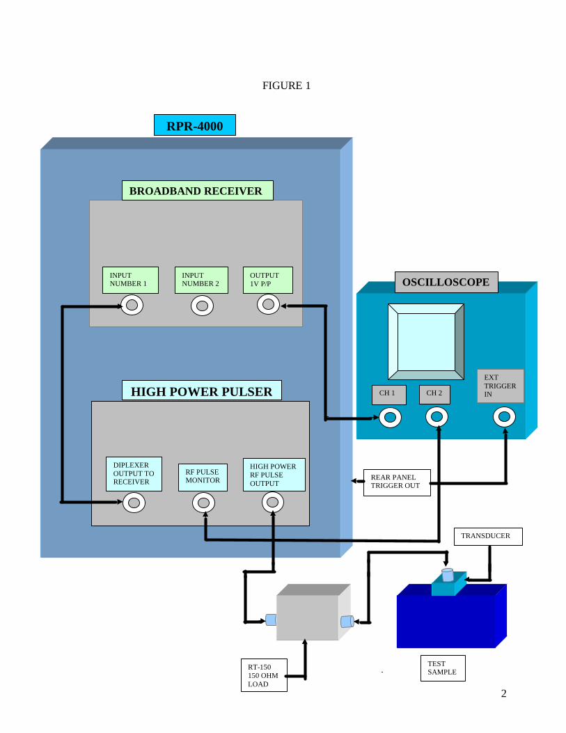
RPR-4000 Transmission/Receive Setup Operating the RPR-4000 Pulser/Receiver in the two standard modes of operation (Pulse-Echo and Through Transmission) is very straight forward. (It should be noted that the instrument can operate from any line voltage from 90 to 240VAC). A block diagram for the Pulse-Echo operation is shown in figure 1. For Pulse-Echo operation proceed as follows:
1. Connect a short coaxial cable from “Diplexer Output to Receiver” to Receiver “Input Number 1”.
2. If using a piezo-electric transducer, connect coax cables from “High Power RF Pulse Output” to an RT-150 (150 ohm high power load) and then to an appropriate transducer. If an electromagnetic transducer is used, the 150 ohm load is not required.
3. Connect a coaxial cable from “Trigger Out” on the rear panel of the RPR-4000 to the external trigger input on the scope.
4. Connect a coaxial cable from receiver “Output” to a 50 ohm vertical input on the scope. Set scope vertical sensitivity to 0.5 v/cm.
5. Connect a coaxial cable from “RF Pulse Monitor” to a 50 ohm vertical input on the scope. Set scope vertical sensitivity to 2v/cm. (Because the monitor output is down 40 dB [100:1] this vertical sensitivity then corresponds to 100 v/cm).
Note* : The 150 ohm load when used with piezoelectrics serves two functions: A.) Cleans up the base line during the RF pulse. B.) Allows the control algorithm for output level to function with higher resolution.
6. Using the keypad on the front panel set the various operating parameters as follows: Frequency: To match the transducer Pulse Width: Typically 5 cycles Repetition Rate: 100pps Control: 10 Receiver Input: Number 1 Receiver Gain: 40dB Receiver High Pass Filter at 100 KHz Receiver Low Pass Filter at 20 MHz
It should now be possible to obtain return signals from the test sample (after turning on the high voltage). Fine adjustments of all control parameters can then be carried out. Please note that some piezo-electric transducers will not tolerate the very large pulse outputs available from the RPR-4000. The maximum output available is approximately 2000 volts pk-to-pk. On the other hand EMATS, which are usually very low impedance, can typically tolerate the full output from the pulser.
2
FIGURE 1
BROADBAND RECEIVER
HIGH POWER PULSER
INPUT NUMBER 1
INPUT NUMBER 2
OUTPUT 1V P/P
DIPLEXER OUTPUT TO RECEIVER
RF PULSE MONITOR
HIGH POWER RF PULSE OUTPUT
CH 1 CH 2
EXT TRIGGER IN
OSCILLOSCOPE
TEST SAMPLE
TRANSDUCER
RT-150 150 OHM LOAD
RPR-4000
REAR PANEL TRIGGER OUT

3
For operation in thru-transmission simply connect the output from a second pick-up transducer to receiver “Input Number 2” and select that input with the keypad. The keypad will also allow the instrument to toggle back and forth between the two received inputs. All operation parameters can be independently set for the two received inputs even when the instrument toggles between the two inputs based on the repetition rate selected. A block diagram for the thru-transmission operation is shown in figure 2.

4
FIGURE 2
BROADBAND RECEIVER
HIGH POWER PULSER
INPUT NUMBER 1
INPUT NUMBER 2
OUTPUT 1V P/P
DIPLEXER OUTPUT TO RECEIVER
RF PULSE MONITOR
HIGH POWER RF PULSE OUTPUT
CH 1 CH 2
EXT TRIGGER IN
OSCILLOSCOPE
TEST SAMPLE
RECEIVE
RT-150 150 OHM LOAD
RPR-4000
REAR PANEL TRIGGER OUT
XMIT

5
AMPLIFIER MODE The RPR-4000 may be used as an amplifier by connecting an arbitrary waveform generator to the rear panel inputs. Apply a sinewave to the “CW” input on the rear panel. The signal must not exceed 1V P/P. Apply a positive TTL gate to the “AMP GATE INPUT” which goes positive (+5V) at
the beginning of the burst and goes to zero volts at the end of the burst. Care must be taken to avoid applying the wrong polarity gate as this will effect the output duty cycle and may cause damage to the unit. Set the frequency setting on the front console to 00.000000 Hz. Set the trigger setting to “EXT”. Maximum duty cycle must be limited to 1% by the user. Allowing higher duty cycle may cause damage to the unit. To help prevent this an “external excessive duty cycle” limiter has been added to protect it from inadvertently operating at an excessive duty cycle with external signals applied via the rear panel connectors. When an excessive duty cycle has been applied, a red LED on the rear panel will light and the 24 volt supply will shut down. Turn the unit power off for a period of 3 to 5 minutes to allow the thermal fuse to cool. Reset the external duty cycle to 1% or less. When the unit power is restored the LED should be off, if not, remove power long enough to allow additional cooling. NOTE: If RPR-4000 frequency setting is set to 00.000000Hz and no external gate is applied for a period of time (approximately 20 minutes) the displayed peak detector voltage will gradually drift to a level which will result in an OverVoltage condition and will be indicated by a beeping sound and message on the front panel display. This condition will not harm the instrument, but the operator should be aware. If this condition occurs, it can be terminated by entering a frequency setting with trigger set to INT. or by cycling system power.

6
SECTION VII WARRANTY All RITEC instruments are warranted against defects in material and workmanship for a period of one year after date of shipment. RITEC agrees to repair or replace any assembly or component found to be defective after normal use during this period. RITEC’s obligation under this warranty is limited solely to repairing any such instrument which, in RITEC’s sole opinion, proves to be defective within the scope of the warranty when returned to the factory. Transportation to the factory is to be prepaid by the purchaser. Shipment should not be made without prior authorization by RITEC. This warranty does not apply to any products repaired or altered by persons not authorized by RITEC, or not in accordance with instructions furnished by RITEC. If the instrument is defective as a result of misuse, improper repair, or abnormal conditions or operations, repairs will be billed at cost. RITEC assumes no responsibility for its product being used in a hazardous or dangerous manner either alone or in conjunction with other equipment. High voltage used in some instruments may be dangerous if misused. Special disclaimers apply to these instruments. RITEC assumes no liability for secondary charges or consequential damages and, in any event, RITEC’s liability for breach of warranty under any contract or otherwise shall not exceed the purchase price of the specific instrument shipped and against which a claim is made. Any recommendations made by RITEC for use of its products are based upon tests believed to be reliable, but RITEC makes no warranty of the results to be obtained. This warranty is in lieu of all other warranties, expressed or implied, and no representative or person is authorized to represent or assume for RITEC any liability in conjunction with the sale of our products other than set forth herin. This warranty covers only items manufactured by RITEC. It specifically excludes all items sold by RITEC which were manufactured by other companies. All of these items are subject to their original individual manufacturer’s warranty. Any claims for defective merchandise should be made to the original manufacturer for these items.