rpm30241ev6 & rpm30242ev6 user manual r1
TRANSCRIPT

RPM30241EV6 RPM30242EV6
(Remote Power Manager)
User’s Manual

Table of Contents
1. IMPORTANT SAFETY INSTRUCTIONS .................................................................................. 2
2. Introduction ............................................................................................................................... 4
3. RPM Package ........................................................................................................................... 5
4. Function .................................................................................................................................... 6
5. Installation ................................................................................................................................ 8
6. Web Interface ........................................................................................................................... 9
7. Specifications .......................................................................................................................... 29
8. Obtaining Service ................................................................................................................... 30
9. Limited Product Warranty ....................................................................................................... 31

2
1. IMPORTANT SAFETY INSTRUCTIONS This manual contains important instructions that should be followed during the installation and the operation of the Remote Power Manager (RPM).
SAVE THESE INSTRUCTIONS An Important Notice To ensure safety a Qualified Service Personnel should perform the installation. Make sure that the AC Utility outlet is properly grounded. Do not open the unit there are no user serviceable parts inside. Servicing of RPM should be
performed by Qualified Service Personnel Only. Please make sure that the input voltage of the RPM matches the supply voltage. Make sure the RPM is installed in the proper environment as specified. This RPM series is ONLY intended to be installed in an indoor temperature controlled environment
that is free of conductive contaminants. Do not operate the RPM in: extremely dusty and/or unclean areas, locations near heating devices,
water or excessive humidity, or where the RPM is exposed to direct sunlight. Select a location, which will provide good air circulation for the RPM at all times. CAUTION – To reduce the risk of fire, connect only to a branch circuit with over current protection in
accordance with the National Electric Code. CAUTION - Connect the RPM to a two pole, three wire grounding AC wall outlet. The receptacle
must be connected to the appropriate branch protection (circuit breaker or fuse). Connection to any other type of receptacle may result in a shock hazard and violate local electrical codes. Do not use extension cords, adapter plugs, or surge strips.
Route power cords so they cannot be walked on or damaged. CAUTION - To reduce the risk of electrical shock with the installation of this RPM equipment and the
connected equipment, the user must ensure that the combined sum of the AC leakage current does not exceed 3.5mA.
CAUTION - To de-energize the outputs of the RPM: Disconnect the RPM from the AC wall outlet. CAUTION - Do not install this device if there is not at least 30 feet (10 meters) or more of wire
between the electrical outlet and the electrical service panel.
3
Receiving Inspection After removing your RPM from its carton, it should be inspected for damage that may have occurred in shipping. Immediately notify the carrier and place of purchase if any damage is found. Warranty claims for damage caused by the carrier will not be honored. The packing materials that your RPM was shipped in are carefully designed to minimize any shipping damage. In the unlikely case that the RPM needs to be returned to MINUTEMAN, please use the original packing material. Since MINUTEMAN is not responsible for shipping damage incurred when the system is returned, the original packing material is inexpensive insurance. PLEASE SAVE THE PACKING MATERIALS! Para Systems Life Support Policy As a general policy, Para Systems Inc. (Para Systems) does not recommend the use of any of its products in life support applications where failure or malfunction of the Para Systems product can be reasonably expected to cause failure of the life support device or to significantly affect its safety or effectiveness. Para Systems does not recommend the use of any of its products in direct patient care. Para Systems will not knowingly sell its products for use in such applications unless it receives in writing assurances satisfactory to Para Systems that (a) the risks of injury or damage have been minimized, (b) the customer assumes all such risks, and (c) the liability of Para Systems Inc. is adequately protected under the circumstances. © COPYRIGHT 2015 BY PARA SYSTEMS, INC. All Rights Reserved. All rights of this User Manual (“Manual”), including but not limited to the content, information, and figures are solely owned and reserved by Para Systems, Inc. (“Para Systems”). The Manual can only be applied to the operation or the use of this product. Any disposition, duplication, dissemination, reproduction, modification, translation, extraction, or usage of this Manual in whole or in part is prohibited without the prior written permission of Para Systems. Given that Para Systems will continuously improve and develop the product, changes may be made to the information in this Manual at any time without obligation to notify any person of such revision or changes. Para Systems will make all possible efforts to secure the accuracy and the integrity of this Manual. Para Systems disclaims any kinds or forms of warranty, guarantee, or undertaking, either expressly or implicitly, including but not limited to the completeness, faultlessness, accuracy, non-infringement, merchantability or fitness for a particular purpose of the Manual.

4
2. Introduction
The RPM is an Internet ready device designed and equipped with an intelligent current-meter (True RMS) that will indicate the total power consumption of the RPM.
Features:
Built-in Web Server to support Remote Power Management Local LED displays Amps, IP Address ,Temperature or Humidity Daily, Weekly, Monthly & Yearly Power Consumption Data 10/100 Base-T Ethernet Port IPv4 and IPv6 support SNMP support (v1,v2c,v3) Telnet, SSHv2 Encryption support Radius Authentication User Account for three different permissions management systems Alarm notification via Email, SNMP, Syslog, LED or audible alarm SSL Web Browser (Https) for set up and operation IP Address filtering Maximum 5000 entries for each power consumption Data and Event log Remote firmware upgrade support SNMP Heart Beat Trap available Reports in Fahrenheit or Celsius Export and Import RPM configuration True RMS current measurement Provides Voltage, Frequency, Power Factor, Active power, Apparent power and kWh information Remote outlet On/Off power switching Remote outlet current monitoring User defined alarm thresholds for Warning and Overload User defined power On/OFF sequence timing Timed & Scheduled On/Off/Reboot switching Alternative outlet restart mode: Memorize previous status, Always On or Always Off Ping-No-Answer alarm Outlet Action via Pre-set Event, Including Power Event, Environment Event and Receiving Trap
from other devices Circuit Breaker protection Free bundle Management Utility

5
3. RPM Package
The standard RPM package contains a Remote Power Manager unit with supporting hardware. The contents of the package are:
Remote Power Manager Unit.
The rackmount brackets are installed on the RPM.
CD-ROM, which contains:
User Manual
RPM Utility Manual
Warranty Card
MIB files
RPM Utility Software
Adobe Acrobat Reader

6
4. Function
Functions Description
Circuit Breakers Overload protection.
LED Indicators
ON / OFF (green) LEDs: On means the outlet is active. Off means the outlet is not active.
Threshold (red) LEDs: On means the current has exceed the threshold setting. Off means the current has not exceed the threshold setting.
Warning (red) LED: On means the RPM is Overloaded. SSL (blue) LED: On means the web access is protected by SSL. DHCP (green) LED: On means the RPM gets its IP address by
DHCP.
Meter 3 digits will display the current draw (in amps) or the IP Address or the temperature and humidity.
ID 1-digit will display the identification number of the RPM.
Function Button
Press and release the function button to turn off the audible alarm. Note: The overload alarm cannot be silenced. Press and hold the function button for 1 beep, then release will
display the ID number, the temperature and the humidity for both of the Temperature/Humidity Probes.
Press and hold the function button for 2 beeps, then release will display the IP address.
Press and hold the function button for 3 beeps, then release will enable the SSL function.
Press and hold the function button for 4 beeps, then release will change the way to set the IP address by either DHCP or fixed IP.
Press and hold the function button for 6 beeps, then release resets the RPM back to the default setting.

7
ENV1 & ENV2 The two RJ11 ports are for the Temperature/Humidity probes.
Audible Alarm
Warning- 1 beep per 1 second. Overload- 3 beeps per 1 second. Note: The audible alarm will continue to beep until the current is lower than the threshold by 0.5 amps.
Ethernet The RJ45 port is for the network communication.
Outlets A ~ X Each individual outlet can be controlled and monitored.
Power Cord Connect to utility power

8
5. Installation
This RPM series is ONLY intended to be installed in an indoor temperature controlled environment that is free of conductive contaminants. DO NOT operate the RPM in: extremely dusty and/or unclean areas, locations near heating devices, water or excessive humidity, or where the RPM is exposed to direct sunlight. Select a location, which will provide good air circulation for the RPM at all times. Route power cords so they cannot be walked on or damaged.
To ensure safety a Qualified Service Personnel should perform the installation.
Make sure that the AC Utility outlet is properly grounded.
Do not install the RPM if there is not at least 30 feet (10 meters) or more of wire between the electrical outlet and the electrical service panel.
The RPM comes with the mounting brackets pre-installed. To mount the RPM into a rack perform the following procedure:
1. Select the desired location for the RPM.
2. Align the mounting holes of brackets with the notched hole on the vertical rail and attach with the retaining screws.
3. Connect the Ethernet cable to the RPM.
4. Connect the output devices to the RPM outlets.
5. Connect the input power cord of the RPM to the wall outlet.
Note 1: The default setting for the IP address is DHCP enabled. If the RPM cannot get the IP from DHCP server, the IP address will stay at the default IP address 192.168.0.216
Note 2: To setup the network system for RPM, it is strongly recommended to build up the power monitoring network system, which is isolated from the others, in order to maintain reliable system operation.

9
6. Web Interface
Login:
Enter the IP address of the RPM in a web browser.
Note: The default setting for the IP address is DHCP enabled. If the RPM cannot get the IP from the DHCP server, the IP address will remain at the default IP address 192.168.0.216
The default user Name is snmp.
The default Password is 1234.

10
Information: Overview
This section shows the information about the RPM Power, the last five events that have occurred, and the status of the individual outlets. Because different models provide different information, the model you have may not display the same information.
Outlet Status Setting Column:
S The schedule function is set. The RPM will execute the preset action according to the schedule.
P The ping function is active. If the specified device stops responding to the ping, the RPM will execute the preset action according to the ping function.
E The RPM will execute the preset action when the event occurs according to the event action..

11
Information: Power
This section shows the information about the power, the current draw and status for each individual outlet.
Information: System
This section shows the information about the System, Network and SNMP:

12
Information: Event Log
This table lists all the events that have occurred. The existing values are overwritten when the maximum number of entries (5000) has been reached. You can filter the log based on specific dates and times. The event logs can be downloaded and saved for future reference.
Information: Data Log
This table lists all of the saved power and environmental data. The existing values are over written when the maximum number of entries (5000) has been reached. You can filter the log based on specific dates and times. The event logs can be downloaded and saved for future reference.

13
Management: Control
This allows the specified users to control the outlets.
Select the outlet by checking the box and then click the ON or the OFF button to control the outlet.
ON: Press the ON button to turn on the assigned outlets.
OFF: Press the OFF button to turn off the assigned outlets.
Restart: Press the Restart button to reboot (off/on) the assigned outlets.
Make Group: Press the Make Group button to set up groups for the outlets.
Delete: Delete a group.
Rename: Rename a group.
Note: After the RPM is plugged into the main power, the RPM will automatically start to sequentially turn on the outlets according to the preset delay time. The default setting for delay time is one second for each outlet; therefore the three circuits with 8 outlets each will take 8-seconds to complete the start-up sequence. If the RPM is unplugged from the main power before the start-up sequence is completed, the outlets, which were not turned on will remain off. The next time the RPM is plugged into the main power, these outlets will not be automatically turned on. These outlets can only be turned on via the web interface.

14
Make Group: This allows the administrator to assign the outlets to make a group. Click on the Group button. Name the group (36 characters max), select the outlets to include in the group and click Add. Select the check box by the group that you want to control.

15
Management: Schedule This allows the administrator to schedule turning OFF/ON the RPM’s outlets.
Outlet: Assign the outlet to be controlled in this schedule.
Outlet Action: Select the action you want to occur.
Date: When selecting the Once option a specific date must be entered. When selecting the ‘Every’ option you can set the schedule for an outlet using an assigned weekly day, or every day.
Time: Set the time for the action to occur.

16
Management: Ping Action
This allows the administrator to Ping the device that is connected to a specific outlet and if there is no response the RPM will automatically cycle power to a locked device connected to the specified outlet by rebooting the outlet.
Outlet: Select which outlet to perform the Outlet Action.
IP Address: Set the IP address of the device to be monitored by the RPM.
Response 5 minutes: The RPM will ping the assigned IP address once each minute. If the device does not respond, then the RPM will repeat the ping once every minute, if the device does not respond after 5 attempts (5 minutes), the RPM will carry out the assigned action automatically.
Action: Select the outlet action “OFF, ON, ON/OFF or “OFF/ON”
Add: Enables this function.
To delete a Ping action, select the action from the list and select Delete.

17
Management: Event Action
This allows the administrator to setup specific actions based on a selected event. The RPM can also receive SNMP traps from a specified device and then perform the selected action.
Event
Device: When the current for entire RPM exceeds the Warning or Overload thresholds the RPM will perform the action setup under the Action. Outlet: When the current for an individual outlet exceeds the Warning or Overload thresholds the RPM will perform the action setup under the Action. ENV: When the temperature or humidity exceeds the thresholds the RPM will perform the action setup under the Action. Receive Trap: When the RPM receives a trap from the specified device the RPM will perform the action setup under the Action. Enter the specific trap OID information and the IP address of the device sending the trap to the RPM.
Action: The RPM will perform the action based on the configured event.
Once the Event and the Action have been setup click Add to saving the settings.
Note: To setup the thresholds for the Device, the Outlets or the ENV, see the Management Threshold section.
The Event Address List provides a list of all of the configured events. To delete an event select the box in front of the event then click Delete.

18
Management: Device
This allows the administrator to configure the outlet name, the delay time and setup different users for specific outlets.
Outlet Configuration Outlet Name: Rename the outlet. Delay ON: Set the delay time in seconds for the power on sequence. Delay OFF: Set the delay time in seconds for the power off sequence. After Restart: Set the desired status you want the outlet to be after the outlet has been restarted. Owner: The administrator can setup different users for specific outlets. The user accounts must be setup first, see the Configuration User tab. Click Apply to save the settings, once the setup is complete.
Note: The maximum delay times are 9999 seconds.
Energy Configuration
Carbon Emission Rate: Set the Carbon Emission Rate and then select Apply to saving the setting.
Note: After the RPM is plugged into the main power, the RPM will automatically start to sequentially turn on the outlets according to the preset delay time. The default setting for delay time is one second for each outlet; therefore the three circuits with 8 outlets each will take 8-seconds to complete the start-up sequence.

19
If the RPM is unplugged from the main power before the start-up sequence is completed, the outlets, which were not turned on will remain off. The next time the RPM is plugged into the main power, these outlets will not be automatically turned on. These outlets can only be turned on via the web interface.
Management: Threshold
This allows the administrator to configure the thresholds for the environmental probe, the entire RPM and each individual outlet.
ENV Threshold Configuration: Set the lower and upper thresholds for the optional environmental probe then click Modify to change the settings. Once these thresholds are set see the management Event Actions to configure the actions based on these thresholds. Device Threshold Configuration: Set the warning and overload thresholds for entire RPM then click Modify to change the settings. Once these thresholds are set see the management Event Actions to configure the actions based on these thresholds. Outlet Threshold Configuration: Set the warning and overload thresholds for each individual outlet then click Modify to change the settings. Once these thresholds are set see the Management Event Actions to configure the actions based on these thresholds.

20
Configuration: Network
This allows the administrator to configure the network settings.
TCP/IP Settings for IPv4 Host Name: The host name of the RPM. DHCP Client: Enable/Disable DHCP to get the IP address from a DHCP server. The default setting for DHCP is enabled. IP Address: The IP address of the RPM. The default static IP address is 192.168.0.216. Subnet Mask: The subnet mask for your network. Gateway IP: The IP address of the IVP4 network gateway. DNS Server1: The IP address of the primary DNS server. DNS Server1: The IP address of the secondary DNS server. Once the information has been entered click Apply to save the settings.
TCP/IP Settings for IPv6
DHCP Client: Enable/Disable DHCP to get the IP address from DHCP server. The default setting for the IPv6 DHCP is disabled. IP Address: The IPv6 address of the RPM. Default Gateway Address: The IP address of the IPv6 network gateway. Once the information has been entered click Apply to save the settings.

21
Configuration: Security
This allows the administrator to configure the security settings to prevent unauthorized users from accessing the RPM.
HTTP Configuration
Server: Enabling or disabling the HTTP connection with the RPM. SSL: Enable or Disable the SSL function. The user may configure HTTPS protocol to use a port number other than standard HTTPS port (443). Redirect HTTP to HTTPS: Change from the standard HTTP protocol to the HTTPS protocol. Port Number: The user may configure port number for the HTTP port (default: 80) or the port number for the HTTPS port (default: 443). Once the information has been entered click Apply to save the settings.
Telnet Configuration
Server: Enabling or disabling the Telnet connection with the RPM. SSH: Enabling or disabling the SSH connection with the RPM. Port Number: The user may configure Telnet protocol to use a port number other than standard Telnet port (23). Once the information has been entered click Apply to save the settings.
IP Filter: Use the IP filter to lockout unauthorized users. Once the information has been entered click Add to save the settings.

22
Configuration: User
This allows the administrator to add users and give them specific rights.
No.: This is the number of users. The maximum number of users is eight. User: This is the user’s login name. The default administrator’s name is snmp. Password: This is the user’s login password. The default password for the administrator is 1234. Permission:
Administrator: Full authority to monitor, control and configure RPM. Default name is snmp and the default password is 1234. Power user: Monitor the RPM, control the specified outlets. No permission to configure RPM. Default password is password. View Only: Monitor the RPM only. No permission to control or configure the RPM. Default password is password.
Email: Enter an email address for the recipient you want to receive the notification.
To add a new user: 1. Enter the user name and then click New. 2. Enter the password 3. Confirm the password 4. Select the Permission rights 5. Enter the email address if the user is to receive emails 6. Select the pencil icon (Modify) to save the settings.
Select the X icon (Delete) to delete a user.
Note: See the Management Device tab to give each user rights to specific outlets.

23
Configuration: Mail
This allows the administrator to setup the email notification. When an event occurs, the RPM can send out email messages to predefined accounts.
Email Server: Enter the Hostname or IP address of the SMTP Mail Server that will be used to send emails. If entering a Hostname, you are also required to enter the DNS Address, see the Configuration Network tab.
Port: Enter the port number for the SMTP server. The default port is 25.
TLS/SSL: Check this box if using secure email.
Email Server Requires Authorization: Check this box if the Mail Server requires authentication to send emails.
Account Name: Enter the account name if SMTP authentication is required.
Password: Enter the password if SMTP authentication is required.
Test: Input the recipient’s email address.
Click on the Send button to send the test email.
Click Apply to save all of the settings. The email message format is as follows: Indicates the Outlets A ~ H-XXXXXXXX status in order When X=0: It means the outlet is off. When X=1: It means the outlet is on.
NOTE: The email recipient’s email address must be entered in the Configuration User tab.

24
Configuration: SNMP
The RPM supports the SNMPv1, v2c and v3 traps to satisfy most of the user’s environment. This allows the administrator to setup the SNMP Traps. When an event occurs, the RPM can send out SNMP Traps to predefined targets.
Once the SNMP configuration is complete click the Apply button to save the settings.

25
Configuration: Time
This allows the administrator to setup the system time for the scheduled events.
Time Configuration: Set the date and time manually, and then click the Apply button to save the settings.
SNTP Configuration: Activate and then setup the Timeserver. Click the Apply button to save the settings.

26
Configuration: Radius
This allows the administrator to configure the RADIUS parameters. Remote Authentication Dial-In User Service (RADIUS) is a widely deployed protocol enabling centralized authentication, authorization, and accounting for network access.
RADIUS: Enable or Disable the RADIUS function.
Primary Server: Input the Primary Server's IP address.
Shared Secret: Input the Shared Secret of Primary Server.
Port: Input the RADIUS UDP port for the primary server.
Timeout: Set the packet timeout interval.
Retries: Set the number of retries before locking out the user.
Secondary Server: Input the Secondary RADIUS Server's IP address.
Shared Secret: Input the Shared Secret of Secondary Server.
Port: Input the RADIUS UDP port for the secondary server.
Timeout: Set the packet timeout interval.
Retries: Set the number of retries before locking out the user.
Click on the Apply button to save the changes.
27
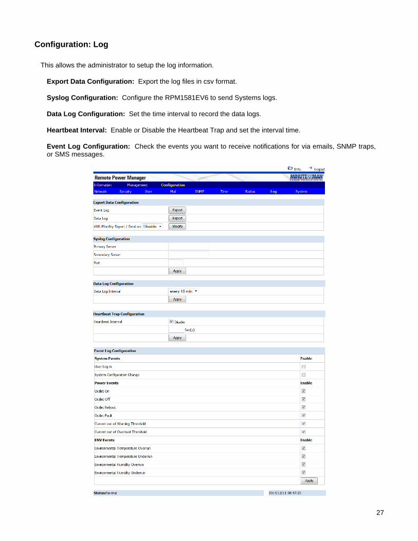
Configuration: Log
This allows the administrator to setup the log information.
Export Data Configuration: Export the log files in csv format.
Syslog Configuration: Configure the RPM1581EV6 to send Systems logs.
Data Log Configuration: Set the time interval to record the data logs.
Heartbeat Interval: Enable or Disable the Heartbeat Trap and set the interval time.
Event Log Configuration: Check the events you want to receive notifications for via emails, SNMP traps, or SMS messages.

28
Configuration: System
This allows the administrator to configure the system.
System Configuration: Configure one RPM and then its configuration file can be saved and then uploaded to another RPM.
Firmware Upgrade: The firmware can be upgraded via the web page.
Reset System: Reset the system back to the factory default setting.
Hardware Reset Button Definition: Configure how the reset button functions.
Temperature Scale: Configure how the temperature for the external Temp/Humidity probe will be displayed.
Auto Logout: Configure the amount of time before the system will log you off.

29
7. Specifications Model Number
RPM30241EV6 RPM30242EV6
Load Capacity (Max)
24Amps
INPUT PARAMETERS Number of Phases Single (12W +G) Nominal Voltage 100-120VAC 200-240VAC Frequency 50/60Hz Input Protection Re-settable circuit breaker OUTPUT PARAMETERS Nominal Voltage 100-120VAC 200-240VAC Frequency 50/60Hz Branch Circuit Protection
UL 60950-1
Circuit Quantity Three ENVIRONMENTAL Operating Temperature +32 - +122F (0 - 50C)
Storage Temperature +32 - +149F (0 - 65C)
Operating/Storage Humidity
0 - 90%, non-condensing
Operating Elevation 0 to 3,000m (0 to +10,000 ft) Storage Elevation 0 to 15,000m (0 to +50,000 ft) PHYSICAL Input Power Cord 10-feet attached Input Plug NEMA L5-30P NEMA L6-30P Quantity Output Receptacles
24
Type Output Receptacles
NEMA 5-15/20R
IEC 320 3 – C19, 21 – C13
Rack Mounting Format
Vertical (Zero U)
Net Dimension L x W x H (mm)
70 x 2.2 x 3.15" (1778 x 56 80)
Net Weight Lbs (Kgs)
18.52 (8.4)
18.74 (8.5)
Ship Dimensions L x W x H (mm)
74.71 x 4.33 8.66" (1890 x 110 220)
Ship Weight Lbs (Kgs)
21.16 (9.6)
21.38 (9.7)
REGULATORY COMPLIANCE Safety/Approvals cUL, UL 60950-1, CE, RoHS2 (EU Directive 2011/65/EU)

30
8. Obtaining Service
For Technical Support on the Web, please visit the Support section of our Web site or visit our online Discussion Forum.
1. Verify there are no tripped circuit breakers. A tripped circuit breaker is the most common issue.
2. Call your dealer for assistance. If you cannot reach your dealer, or if they cannot
resolve the issue call or fax the Technical Support department at the following numbers; Voice phone (972) 446-7363, FAX line (972) 446-9011 or visit our Web site at www.minutemanups.com the "Discussion Board". Before calling the Technical Support Department have the following information available:
a) Contact name and address. b) Where and when the unit was purchased. c) All of the model information about your unit. d) The serial number of your unit. e) Any information on the failure, including LEDs that may be illuminated or error
codes displayed. f) A description of the protected equipment including model numbers, if possible. g) A technician will ask you for the above information and if possible, help solve the
issue over the phone. In the event that the unit requires factory service, the technician will issue you a Return Material Authorization Number (RMA #). NOTE: We must have the model number and the serial number of the product to issue the RMA #.
h) If the unit is under warranty, the repairs will be done at no charge. If the unit is not under warranty there will be a charge for the repair.
3. Pack the unit in its original packaging. If the original packaging is no longer available,
ask the Technical Support Technician about obtaining a new set. It is important to pack the unit properly in order to avoid damage in transit. Never use Styrofoam beads for a packing material.
a) Include a letter with your name, address, day time phone number, RMA number, a copy of your original sales receipt, and a brief description of the problem.
4. Mark the RMA # on the outside of all packages. The factory cannot accept any
package without the RMA # marked on the outside.
5. Return the unit by insured, prepaid carrier to:
Para Systems Inc. MINUTEMAN UPS
1809 W. Frankford Road, Suite 150 Carrollton, TX 75007
ATTN: RMA #
31
9. Limited Product Warranty Para Systems, Inc. (Para Systems) warrants this equipment, when properly applied and operated within specified conditions, against faulty materials (excluding the batteries) or workmanship for a period of three years from the date of purchase. Para Systems Inc. (Para Systems) warrants the batteries for a period of two years from the date of purchase. For equipment sites within the United States and Canada, this warranty covers depot repair or replacement of defective equipment at the discretion of Para Systems. Depot repair will be from the nearest authorized service center. The customer pays for shipping the product to Para Systems. Para Systems pays ground freight to ship the product back to the customer. Replacement parts and warranty labor will be borne by Para Systems. For equipment located outside of the United States and Canada, Para Systems only covers faulty parts. Para Systems products that are depot repaired or replaced pursuant to this warranty shall only be warranted for the unexpired portion of the warranty applying to the original product. This warranty applies only to the original purchaser who must have properly registered the product within 10 days of purchase. The warranty shall be void if (a) the equipment is damaged by the customer, is improperly used, is subjected to an adverse operating environment, or is operated outside the limits of its electrical specifications; (b) the equipment is repaired or modified by anyone other than Para Systems or Para Systems approved personnel; or (c) has been used in a manner contrary to the product’s User's Manual or other written instructions. Any technical advice furnished before or after delivery in regard to use or application of Para Systems’ equipment is furnished without charge and on the basis that it represents Para Systems’ best judgment under the circumstances, but it is used at the recipient’s sole risk. EXCEPT AS PROVIDED HEREIN, PARA SYSTEMS MAKES NO WARRANTIES, EXPRESSED OR IMPLIED, INCLUDING WARRANTIES OF MERCHANTABILITY AND FITNESS FOR A PARTICULAR PURPOSE. Some states do not permit limitation of implied warranties; therefore, the aforesaid limitation(s) may not apply to the purchaser. EXCEPT AS PROVIDED ABOVE, IN NO EVENT WILL PARA SYSTEMS BE LIABLE FOR DIRECT, INDIRECT, SPECIAL, INCIDENTAL, OR CONSEQUENTIAL DAMAGES ARISING OUT OF THE USE OF THIS PRODUCT, EVEN IF ADVISED OF THE POSSIBILITY OF SUCH DAMAGE. Specifically, Para Systems is not liable for any costs, such as; labor for on-site installation, on-site maintenance or on-site service, lost profits or revenue, loss of equipment, loss of use of equipment, loss of software, loss of data, cost of substitutes, claims by third parties, or otherwise. The sole and exclusive remedy for breach of any warranty, expressed or implied, concerning Para Systems’ products and the only obligation of Para Systems hereunder, shall be depot repair or replacement of defective equipment, components, or parts; or, at Para Systems’ option, refund of the purchase price or substitution with an equivalent replacement product. This warranty gives you specific legal rights and you may also have other rights which vary from state to state. No employee, salesman, or agent of Para Systems is authorized to add to or vary the terms of this warranty.
PN: 34000504 R1