rpi field service calibration kit for servicing midmark
TRANSCRIPT

An ISO 9001 Certified Company
RPI FIELD SERVICECALIBRATION KIT
RPI Part #MIK074For servicing the Midmark • Ritter Ultra Clave®
CALL (800) 221-9723 or (818) 882-8611 • FAX (818) 882-7028 • E-MAIL [email protected] • WEBSITE www.rpiparts.com
For use with these models only:M9 (S/N Series: CZ, DA, DB, DX, DY, FD & OM)M9D (S/N Series: FF & FG)M11 (S/N Series: ES, ET, FP, FR & GB)M11D (S/N Series: GC & GC)
This guide has been prepared to help troubleshoot, evaluate and repair the Midmark•Ritter M9 and M11 Ultra-Clave®.
TABLE OF CONTENTS
1.0 – Leak Detection Guide . . . . . . . . . . . . . . . . . . . . . . . . . . . . . . . . . . . . . . . . . . . . . . . . . . . . . . . . . . . . . . . . . . . . . . . . . . . . . . . . . . . . . . 2Identifies areas in which leaks are most likely to occur.
2.0 – Planned Maintenance (PM) Check List . . . . . . . . . . . . . . . . . . . . . . . . . . . . . . . . . . . . . . . . . . . . . . . . . . . . . . . . . . 3Lists step-by-step instructions for replacing most common PM parts including door gasket, dam gasket, filters and door spring.
3.0 – Error Codes and Other Diagnostics . . . . . . . . . . . . . . . . . . . . . . . . . . . . . . . . . . . . . . . . . . . . . . . . . . . . . . . . . . . . . 4-6Provides explanation of error codes as well as other diagnostic tools including a fuse chart, drying cycle dip switch settings infor-mation, and service tips focusing on a low water error and inactive display lights.
4.0 – Door Opening Test Procedure . . . . . . . . . . . . . . . . . . . . . . . . . . . . . . . . . . . . . . . . . . . . . . . . . . . . . . . . . . . . . . . . . 7Provides a test to verify if the door opening relay on the main PC board is functioning.
5.0 – Calibration Procedure – Pressure/Temperature Potentiometer Adjustments . . . . . . . . . . . . . . . . . . . . . . . . . . . . 8-14Offers step-by-step, detailed calibration procedures as well as an at-a-glance version.
6.0 – RPI Parts to fit Midmark • Ritter M9 & M11 Ultra-Clave . . . . . . . . . . . . . . . . . . . . . . . . . . . . . . . . . . . . . . . . . . . . 15Listing of RPI parts that fit the Ultra-Clave and includes the OEM Part # for easy reference.
1

2
1.0 - LEAK DETECTION GUIDE
DOOR and/or DAM GASKET Check for water or steam leaking around the door.
VENT SOLENOID VALVE Check for water or steam leaking back into the reservoir through the condensing coil.
FILL SOLENOID VALVE Check for water leaking back into the reservoir through the fill line by observing an increase in the reservoirwater level and/or presence of bubbles.
BELLOWS VALVE Check for excessive steam from the bellows line in the reservoir. Note: a slight "hiss" of steam is notuncommon.
PRESSURE RELIEF Check for water leaking beneath the back of the sterilizer.VALVE Caution: Release pressure in the sterilizer before replacing the pressure relief valve.
PRESSURE Check for steam leaking onto or around the Main PC board.SENSOR HOSE

FILTERS: MIF038 or MIF062Depending on the age of the machine, you will need to replaceeither the sintered bronze style Chamber Filter (MIF038) or boththe mesh style Chamber Filter and Vent Filter (MIF062). See belowfor instructions.
• Chamber Filter (sintered bronze style filter) – MIF038: If themachine has only a Chamber Filter – Remove all trays and the rackfrom the chamber. Clean the chamber, then remove the old chamber filter. Install new filter. Reinstall rack and trays.
• Chamber & Vent Filters (mesh style filter) – MIF062: If themachine has both a Chamber and a Vent Filter – Remove all traysand the rack from the chamber. Clean the chamber, then remove thechamber filter. Install the new filter. You must also replace the VentFilter that serves as a filter for the steam trap/bellows and is locat-ed in the vent line to the tee fitting. Reinstall rack and trays.
After replacing the parts, check the reservoir and clean if dirt or debrisare present. (Note: Debris is the #1 reason for Steam Trap/Bellowsfailure.) • Refill reservoir with distilled water only. • Conduct a tem-perature check using a Max Register Thermometer (RPI Part#RPT113). • Conduct a pressure check to identify any leaks that mayneed to be addressed.
3
DOOR GASKETS: MIG027 fits M9 and MIG028 fits M11Remove the old door gasket. Clean the gasket groove in the door andchamber face. For easy installation of the new gasket, use the “South-East-West-North” method (i.e. begin installing the gasket at the bot-tom of the door, then install the left and right sides and finish at thetop by squeezing in any of the excess, making sure that the gasket fitsflush).
DAM GASKETS: MIG035 fits M9 and MIG036 fits M11Use CAUTION when removing or installing the dam gasket – the doorstuds can be sharp. To install the door dam, align and place the damgasket on and over the door studs. The dam must lie flat against thedoor (refer to the Installation Instructions included with theMIG035/MIG036 dam gasket).
DOOR SPRING: MIS076Remove the old spring. Reuse the screw to install the two new doorsprings – one on top of the other. This will aid in the door opening.
REP
LACEMENT PARTS INDUSTRIES, INC
.
STERILIZERPLANNED MAINTENANCECHECK
LIST
Sterilizer PM KIt (RPI Part #MIK072) for parts to fit the M9 UltraClave® sterilizer
Sterilizer PM KIt (RPI Part #MIK080) for parts to fit the M11 UltraClave® sterilizer
2.0 - PLANNED MAINTENANCE (PM) CHECK LIST

4
Power interruption to control PC board.
1. Overheat thermostat activates (opens).• Pressure leak during sterilization cycle.• Water sensor shorted (which will result in bypassing of filling
phase).• Chamber water level too low.• High input voltage during drying cycle.• Faulty overheat thermostat.
2. Poor electrical connection or faulty wiring (bad power source tosterilizer).
3. Main PC board may be faulty.
3.0 - ERROR CODES AND OTHER DIAGNOSTICS
The Stop button was depressed during the sterilization cycle.
The On/Standby button was depressed during the sterilization cycle.
Excessive temperature (Temperature exceeds 277˚F).
• Check for pressure leaks. Refer to 1.0 - Leak Detection Guide.• Temperature probe is dirty or malfunctioning.• Sterilizer may need to be re-calibrated. Refer to 5.0 - Calibration
Procedure.
Excessive pressure (Pressure exceeds 35 psi).
• Sterilizer is overloaded.• Bellows is closing prematurely trapping air in the chamber.• Temperature probe is dirty or malfunctioning.• Sterilizer may need to be re-calibrated. Refer to 5.0 - Calibration
Procedure.
Door ajar during sterilization cycle.
• Verify the door latch properly engages the door switch and the switchactivates.
• Check door switch continuity and the wiring connections.
ERROR CODE 1
ERROR CODE 2
ERROR CODE 5
ERROR CODE 6
ERROR CODE 3
ERROR CODE 4

5
Hardware and/or software problem – Watchdog timer reset error.
1. Poor electrical connection or faulty wiring (bad power source tosterilizer).
2. Main PC board may be faulty.
Software interruption error.
• Run additional cycles. If problem continues, replace the Main PCboard.
Ram Test Error.
• Run additional cycles. If problem continues, replace the Main PCboard.
Door malfunction: Error Code 8 – Door switch did not return to normallyopen condition after door pulse solenoid actuated. Error Code 9 –Display Pressure exceeded 0.9 PSI during the Dry cycle.
• If pressure reading is not at zero (0), sterilizer needs to be re-calibrated.Refer to 5.0 - Calibration Procedure.
• If door opens at end of cycle, check door switch continuity (normallyopen).
• If door does not open at end of cycle, refer to 4.0 - Door Opening TestProcedure.
• Inspect door mechanism for smooth operation. Lubricate if necessary.• Check door switch and wire connections.• Check door pulse solenoid.
Pressure display reads less than 24.5 psi.
• Check for pressure leaks. Refer to 1.0 - Leak Detection Guide.• Temperature probe is dirty or malfunctioning.• Sterilizer may need to be re-calibrated. Refer to 5.0 - Calibration
Procedure.
ERROR CODE 7 ERROR CODE 10
ERROR CODE 12
ERROR CODE 11
ERROR CODE 8 or 9
3.0 - ERROR CODES AND OTHER DIAGNOSTICS (continued)

6
Printer FuseFast Acting; 1/4" dia. x 1-1/4" Lg.; 3 Amp, 250 Volt
Line Fuse(s)Fast Acting; 1/4" dia. x 1-1/4" Lg.; 15 Amp, 250 Volt
If sterilizer is overheating in Dry mode, check the settings.
Caution: Disconnect the power cord before changing these settings.Off = Position switch to the left. On = Position switch to the right.
Ground Circuit continuity failed the (5) minute time limit.
If water is continuously filling the chamber:• Check for an open circuit or corrosion on the Water Lever Sensor.• Check temperature probe by disconnecting it from Main PC board.• The fill valve may be stuck in the Open position.
If water flow is restricted or not present:• Check for debris (dirt) on the filter and in the fill lines.• Check fill valve for proper operation or debris.• Water level sensor malfunction.
Sterilizer displays temperature and pressure, but the LED statuslights do not light up.
• Disconnect the power cord and wait 30 seconds (this will reset theinternal CPU). Run additional cycles.
DRYING CYCLE DIP SWITCH SETTING
FUSE CHART (Fuses located on Main PC Board) LOW WATER ERROR
DISPLAY LIGHTS INACTIVE
3.0 - ERROR CODES AND OTHER DIAGNOSTICS (continued)
Coolest: Setting #1#1 OFF#2 OFF#3 ON#4 ON
Cool: Setting #2#1 OFF#2 OFF#3 OFF#4 ON
Warm: Setting #3#1 OFF#2 OFF#3 OFF#4 OFF
Warmest: Setting #4#1 OFF#2 OFF#3 ON#4 OFF
If sterilizer needs todry even cooler -
Setting #5#1 OFF#2 ON#3 ON#4 ON
7
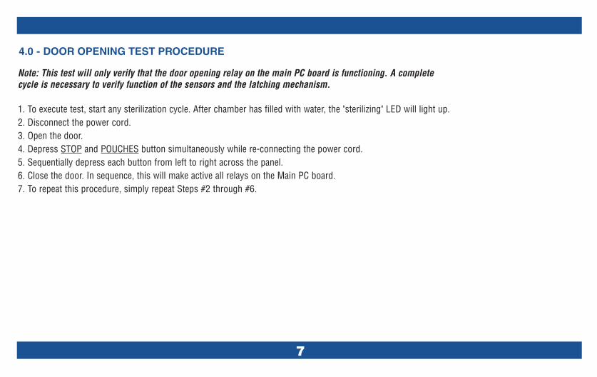
4.0 - DOOR OPENING TEST PROCEDURE
Note: This test will only verify that the door opening relay on the main PC board is functioning. A completecycle is necessary to verify function of the sensors and the latching mechanism.
1. To execute test, start any sterilization cycle. After chamber has filled with water, the "sterilizing" LED will light up.2. Disconnect the power cord.3. Open the door.4. Depress STOP and POUCHES button simultaneously while re-connecting the power cord.5. Sequentially depress each button from left to right across the panel.6. Close the door. In sequence, this will make active all relays on the Main PC board.7. To repeat this procedure, simply repeat Steps #2 through #6.

8
IMPORTANT The Calibration Procedure that begins onpage 9 requires the sterilizer to be plugged in andpowered up while the adjustments are being per-formed. Do not touch any components except for theadjusting screws of the potentiometers. Use the TrimPot Adjustment Tool (RPI Part# RPT460) to set thepotentiometers. DANGER: Failure to comply withthese instructions may result in an electrical shock,which may result in severe personal injury or death.
5.0 - CALIBRATION PROCEDURE - PRESSURE/TEMPERATURE POTENTIOMETER ADJUSTMENTS

9
AT-A-GLANCECALIBRATION PROCEDURE
1) Open door.2) Depress LIQUIDS and PACKS buttons at the same time as plugging in the
power cord.3.) Starting with UNWRAP button, depress and release all buttons from left
to right across panel.4) Turn pressure zero pot #1 counter-clockwise to 0.0 PSI. Then turn clock-
wise until the display pressure reads 0.1 PSI.5) Depending on if the board is old or new, connect multi-meter leads as
shown in Figure 2 on page 13 (old), or Figure 3 on page 14 (new).6) Adjust temperature pot #3 to 2.56 VDC reading on multi-meter. 7) Connect the test pressure gauge, close the door and press the START
button.8) Check for pressure leaks at this time. Refer to 1.0 Leak Detection Guide.9) After display reaches 272˚F, adjust the pressure range pot #2 until the
display pressure matches test pressure gauge to within +/- 0.5 PSI10) Depress the STOP button to end the test cycle.11) After the sterilizer vents and the door opens, unplug the power cord
(main PC board to reset itself).
The pressure zero, pressure range, and temperature potentiometers mustnot be adjusted exclusively. If one potentiometer needs to be adjusted, thenthe entire potentiometer adjustment procedure must be performed, and itmust be performed in the proper sequence as described in the steps below.
INSTRUCTIONS
1) Remove the power cord from the A.C. outlet. Remove right handside panel.
2) Open the sterilizer door.
3) To begin diagnostics, go to page 10, see Figure 1.
5.0 - CALIBRATION PROCEDURE - PRESSURE/TEMPERATURE POTENTIOMETER ADJUSTMENTS (continued)

10
Figure 1 – Diagnostics Procedure (M9 & M11 and M9D & M11D Style Key Pad Displays)
M9 & M11 Style Key Pad Display
M9D & M11D Style Key Pad Display
Step #3 continued from page 9.Read the IMPORTANT note on page 8, before youbegin the following steps.a) Press and hold the LIQUIDS and PACKS buttons
simultaneously while connecting the power cord intoan A.C. outlet.
b) Release the LIQUIDS and PACKS buttons simultane-ously to cause the display PC Board LED's to individ-ually illuminate, and then extinguish one at a time in aleft to right sequence.
c) Press and release the buttons in the following orderand one at a time: UNWRAPPED, POUCHES, LIQ-UIDS, PACKS, START, STOP and ON/STANDBY. Wheneach button is pressed, the corresponding LED willilluminate and stay illuminated. When the sequence iscompleted, the PRESSURE (PSI) display will displaythe pressure that the control PC board is reading andthe TEMP (˚F)/TIME (MIN: SECONDS) display will dis-play the temperature that the control PC board is read-ing. When the displays register proper values, contin-ue with calibration – proceed to Step #4, page 11.

5.0 - CALIBRATION PROCEDURE - PRESSURE/TEMPERATURE POTENTIOMETER ADJUSTMENTS (continued)
11
NOTES: 1) Turning the adjusting screw of the pressure range potentiometer in the clockwise direction raises the sterilizer pressure reading while turning the adjustingscrew in the counter-clockwise direction lowers the sterilizer pressure reading. 2) Turning adjusting screw 1/4 turn raises or lowers the temperature of the sterilizerapproximately 3O˚F (1.67˚C). On old style PC boards, turning the adjusting screw of the temperature potentiometer in the clockwise direction raises the sterilizer tem-perature while turning the adjusting screw in the counter clockwise direction lowers the sterilizer temperature. On new style PC boards, it is the opposite.
4) PRESSURE ZERO ADJUSTMENT (Potentiometer #1): Turn the adjusting screw of the pressure zero potentiometer, #1 (see Figures 2 and 3, pages13-14), in the counter-clockwise direction until the Pressure (psi) display reads 0.0 psi (0.0 kPa). (See Notes 1 and 2 below.) Then turn clockwiseuntil pressure display reads 0.1 psi (kPa).
5) TEMPERATURE ADJUSTMENT (Potentiometer #3): Continue by determining the style of PCB and confirming meter lead attachment points (seeFigures 2 and 3, pages 13-14). Set the multi-meter to read VDC, at least the 5 Volts range. Connect the red lead of the multi-meter to Test Point(A) and the black lead of the multi-meter to Test Point (B). (See Figures 2 and 3, pages 13-14.)
CAUTION Test Points for the multi-meter leads must be connected exactly as shown in the illustration - Figures 2 and 3, pages 13-14. Connectinga lead to the wrong side of the resistor or wrong pin of the chip will result in an incorrect adjustment.
6) The multi-meter should read 2.550 VDC +/- 0.001 VDC. If the multi-meter reading is not 2.550 VDC +/- 0.001 VDC, turn the adjusting screw onthe temperature potentiometer #3 in a clockwise direction to lower the voltage setting or a counter-clockwise direction to raise the voltage settinguntil the multi-meter reading is 2.550 VDC, +/- 0.001 VDC. (See Notes 1 and 2 below.)
NOTE In this step, if the digital multi-meter being used has only three digits, turn the adjusting screw on the potentiometer #3 counter-clockwise(see Figures 2 and 3, pages 13-14) then adjust to a setting of 2.54 VDC and then adjust counter-clockwise to 2.55 VDC.
7) For temperature verification in a later step, place a Max-Register Thermometer on the tray and close the sterilizer door.

8) CONNECTING THE TEST PRESSURE GAUGE TO THE STERILIZER: Disconnect the black tubing from Pressure Sensor and from the barb fitting.Keep black tubing in a safe place for re-installation upon completion of calibration procedure. Then connect the RPI Test Pressure Gauge topressure sensor and the barb fitting – secure using clamps. (Important: See Notes 1 and 2 below. See illustration on page 8.)
9) Press the START button to initiate a test calibration cycle and then wait until the temperature on the TEMP (˚F) / TIME (MIN: SECONDS) displayreaches 272 - 273˚F (133 -134˚C). From a cold start, the wait should be about 9-10 minutes.
10) PRESSURE RANGE ADJUSTMENT (Potentiometer #2): Turn the adjusting screw of the pressure range potentiometer, #2 (see Figures 2 and 3,pages 13-14) in the clockwise or counter-clockwise direction until the reading on the PRESSURE (psi) display matches the reading of the TestPressure Gauge within a tolerance of +/- O.5 psi (3.5 kPa).
11) Check the multi-meter reading, it must still read 2.550 VDC, +/- 0.001 VDC.
12) Press the STOP button to end the test calibration cycle and let the sterilizer vent.
13) Disconnect the power cord from the A.C. outlet, then remove the multi-meter leads from test points A and B (see Figures 2 and 3, page 13-14).
14) Open the sterilizer door and remove the Max-Register Thermometer (RPI Part #RPT113) from the sterilizer tray. Verify that the chambertemperature has reached 272-273˚F (133-134˚C).
15) Repeat Steps #3 and #4 of this procedure (see page 10-11). The display must read 0.1 psi (1 kPa) with the sterilizer door open. If it does not,repeat Calibration Procedure starting with Step #4, page 11.
16) Disconnect the power cord from the A.C. outlet. Remove the Test Pressure Gauge from the sterilizer. Using new cable ties, re-install the originalblack tubing removed in Step #8. Re-install right hand side panel.
17) Run a final test cycle and use Max-Register Thermometer (RPI Part #RPT113) to confirm chamber temperature.
5.0 - CALIBRATION PROCEDURE - PRESSURE/TEMPERATURE POTENTIOMETER ADJUSTMENTS (continued)
12
NOTES: 1) CAUTION Place and tighten the hose Kwik Clamps™ on the fittings in order to secure the hose (see illustration, page 8). 2) After disconnecting Test PressureGauge from the sterilizer, reconnect the black tubing to Pressure Sensor and tube fitting using new hi-temp cable ties (see illustration, page 8).
13
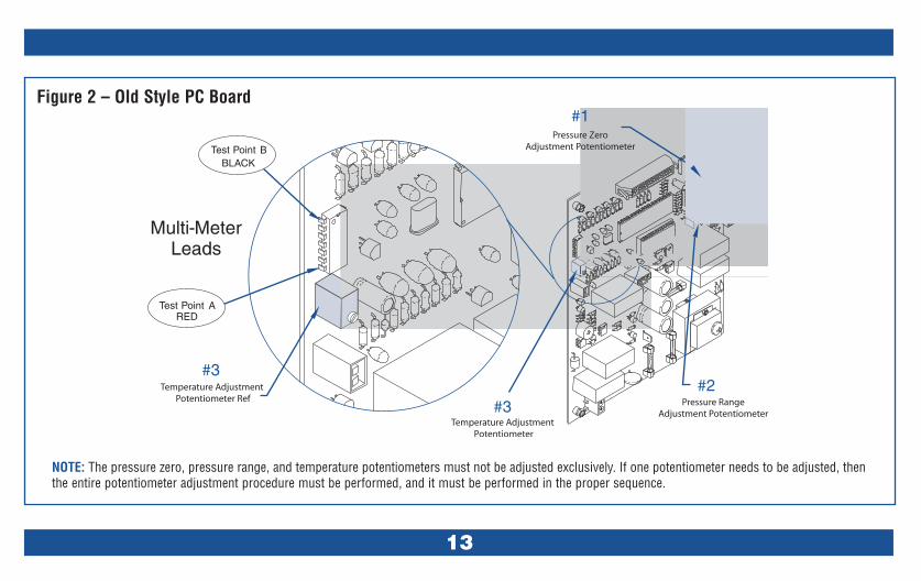
Figure 2 – Old Style PC Board
NOTE: The pressure zero, pressure range, and temperature potentiometers must not be adjusted exclusively. If one potentiometer needs to be adjusted, thenthe entire potentiometer adjustment procedure must be performed, and it must be performed in the proper sequence.
14
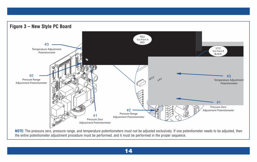
NOTE: The pressure zero, pressure range, and temperature potentiometers must not be adjusted exclusively. If one potentiometer needs to be adjusted, thenthe entire potentiometer adjustment procedure must be performed, and it must be performed in the proper sequence.
Figure 3 – New Style PC Board

RPI
PAR
T#
OEM
PAR
T#
DES
CRIP
TIO
NM
IP05
000
2-03
57-0
0TE
MPE
RAT
UR
EPR
OBE
ASSE
MBL
Y•
•M
IS07
500
2-03
58-0
0W
ATER
LEVE
LSE
NSO
RAS
SY•
•PC
V052
002-
0359
-00
PRES
SUR
ER
ELIE
FVA
LVE
••
MIF
038
002-
0360
-00
FILL
FILT
ER•
•M
IS03
900
2-03
62-0
0D
OO
RSW
ITCH
ASSE
MBL
Y•
•M
IK07
200
2-03
61-0
0ST
ERIL
IZER
PMKI
T-
FITS
M9
•M
IS04
400
2-03
63-0
0PU
LSE
SOLE
NO
ID•
MIS
079
002-
0363
-03
PULS
ESO
LEN
OID
•M
IS04
200
2-03
65-0
0SO
LEN
OID
VALV
E(F
ILL)
••
MIS
043
002-
0366
-00
SOLE
NO
IDVA
LVE
(VEN
T)•
•M
IH04
800
2-03
67-0
0H
EATE
REL
EMEN
TAS
SEM
BLY
•M
IT04
700
2-03
70-0
0O
VER
TEM
PTH
ERM
OST
AT•
•R
PG46
100
2-03
72-0
0TE
STPR
ESSU
RE
GAU
GE
••
MIK
080
002-
0504
-00
STER
ILIZ
ERPM
KIT
-FI
TSM
11•
MIH
049
002-
0505
-00
HEA
TER
ELEM
ENT
ASSE
MBL
Y•
MIV
073
002-
0519
-00
SOLE
NO
IDVA
LVE
(VEN
T)•
•M
IK07
800
2-06
54-0
0ST
EAM
TRAP
KIT
(New
Styl
e)•
•M
IV08
100
2-06
54-0
0ST
EAM
TRAP
(New
Styl
e)•
•M
IF06
200
2-03
60-0
0FI
LL/V
ENT
MES
HCH
AMBE
R-
2/pk
g•
•R
CB08
901
4-01
93-0
0AI
RVE
NT
DIA
PHR
AGM
ASSE
MBL
Y•
•R
CB10
001
4-01
93-0
0AI
RVE
NT
BELL
OW
SAS
SEM
BLY
••
MIS
045
014-
0199
-00
SOLE
NO
IDVA
LVE
(VEN
T)•
MIS
046
014-
0200
-00
SOLE
NO
IDVA
LVE
(FIL
L)•
RPT
480
015-
0013
-05
CABL
ETI
E(H
IGH
TEM
P)-
25/p
kg•
•R
PF04
901
5-03
46-0
8FU
SE-P
RIN
TER
(3A,
250V
)•
•R
PF28
101
5-03
46-0
7FU
SE(1
5A,2
50V)
••
RPR
290
015-
0639
-00
ACR
ECEP
TACL
E,SN
AP-I
N•
•R
PC29
101
5-06
40-0
0PO
WER
COR
DW
/RIG
HT
ANG
LEPL
UG
••
RPB
289
015-
1137
-00
STR
AIN
REL
IEF
BUSH
ING
••
RPC
288
015-
1139
-00
POW
ERCO
RD
W/C
ON
NEC
TOR
S•
•M
IP04
101
6-03
95-0
2D
OO
RIN
SULA
TOR
PAD
•M
IF05
101
6-05
23-0
0LE
VELE
RFE
ET•
•M
IS07
605
0-23
47-0
0D
OO
RSP
RIN
G•
•M
IA08
605
0-23
62-0
0SP
RIN
GAR
M•
MIA
077
050-
3970
-00
SPR
ING
ARM
•M
IC03
705
2-01
73-0
0CO
ND
ENSA
TIO
NCO
IL•
•M
IG02
705
3-03
66-0
0D
OO
RG
ASKE
T•
RPI
268
053-
0385
-00
CHAM
BER
INSU
LATI
ON
•M
IG03
505
3-05
08-0
0D
AMG
ASKE
T•
MIG
028
053-
0527
-00
DO
OR
GAS
KET
•R
PI26
905
3-05
85-0
0CH
AMBE
RIN
SULA
TIO
N•
MIG
036
053-
0784
-00
DAM
GAS
KET
•M
IP04
016
-039
5-01
DO
OR
INSU
LATO
RPA
D•
MIC
057
N/A
COIL
(FIL
LVA
LVE)
••
MIC
058
N/A
COIL
(VEN
TVA
LVE)
••
MIC
059
N/A
COIL
(VEN
TVA
LVE)
•M
IC06
0N
/ACO
IL(F
ILL
VALV
E)•
MIC
083
N/A
COIL
(VEN
TVA
LVE)
••
MIH
052
N/A
ATTA
CHIN
GH
ARD
WAR
E•
•M
IK05
3N
/AR
EPAI
RKI
T(F
ILL
VALV
E)•
•M
IK05
4N
/AR
EPAI
RKI
T(V
ENT
VALV
E)•
•M
IK05
5N
/AR
EPAI
RKI
T(V
ENT
VALV
E)•
MIK
056
N/A
REP
AIR
KIT
(FIL
LVA
LVE)
•M
IK06
1N
/AD
RAI
NH
OSE
KIT
••
MIK
074
N/A
FIEL
DSE
RVI
CECA
LIBR
ATIO
NKI
T®*
••
MIK
082
N/A
REP
AIR
KIT
(VEN
TVA
LVE)
••
PCN
136
N/A
SPEE
DN
UT
••
RPC
463
N/A
KWIK
™CL
AMPS
••
RPC
476
N/A
CAR
RYI
NG
CASE
W/F
OAM
INSE
RTS
••
RPK
282
N/A
PRES
SUR
ETU
BEKI
T•
•R
PT11
3N
/AM
AXR
EGTH
ERM
OM
ETER
••
RPT
460
N/A
TRIM
POT
ADJU
STM
ENT
TOO
L•
•R
PT46
2N
/ATU
BIN
G(S
ILBR
ADE)
-SO
LDBY
THE
FOO
T•
•*
Foru
sew
ithth
ese
mod
els
only
:M9
(S/N
Serie
s:CZ
,DA,
DB,D
X,DY
,FD
&OM
);M
9D(S
/NSe
ries:
FF&
FG);
M11
(S/N
Serie
s:ES
,ET,
FP,F
R&
GB);
and,
M11
D(S
/NSe
ries:
GC&
GC)
M9
M11
6.0
-RPI
Parts
tofit
Mid
mar
k•Ri
tter
M9
&M
11Ul
traCl
ave™
Parts mentioned in this booklet are manufactured by Replacement Parts Industries, Inc. to fit Midmark¥Ritter M9 and M11 Ultra-Clave®.All product names used in this document are trademarks or registered trademarks of their respective holders. All rights reserved © RPI 2005. MIK074INS REV A 11/05
15