rpdg-50/rpdg-100/ rpdg-200
TRANSCRIPT

OPERATION MANUAL
Manual Order Number: 9311-002 Revision Level: 00D
Copyright © 2012 MKS Instruments, Inc. All rights reserved.
RPDG-50/RPDG-100/
RPDG-200 Family of Pulsed DC Plasma Generators
HIGH VOLTAGES MAY BE PRESENT AT THE OUTPUT OF THIS UNIT. All operating personnel should use extreme caution in handling these voltages and be thoroughly familiar with this manual.
CFC's
DO NOT USE ANY CFC (CHLOROFLUOROCARBON) SOLVENT IN THE MAINTENANCE OF THIS PRODUCT. In recognition of our responsibility to protect the environment, this product has been manufactured without the use of CFCs. The no-clean flux now used in all soldering operations may leave a small inert residue that will not affect the performance of the product. The use of CFCs for cleaning or maintenance may result in partial liquification of the no-clean flux residue, which will damage the unit and void the warranty.
ISO 9001QUALITY
SYSTEM
This product is manufactured at an MKS Instruments’ ISO-9001:2000-Quality-System-compliant facility.
Notice The material contained in this manual is subject to change without notice. No part of this manual may be reproduced or utilized in any form or by any means, electronic or mechanical, including photocopying or electronic transmission or other means of reproduction or distribution without prior written consent of MKS, ENI Products. The drawings, specifications and other technical information contained in this manual are the property of MKS, ENI Products and shall not be copied, reproduced or used in any way, in whole or in part, as the basis of manufacture or sale of similar items without the prior written consent of MKS, ENI Products.

IBM is a registered trademark of International Business Machines, Inc. Positronic® is a registered trademark of Positronic Industries, Inc.
Weidmuller® is a registered trademark of Weidmuller, Inc. AMP® is a registered trademark of AMP, Inc.
MDX-10™, Advanced Energy® are registered trademarks of Advanced Energy Industries, Inc.
ProComm™ is a registered trademark of DATASTORM Technologies, Inc. CrossTalk™ is a registered trademark of Attachmate, Inc.
HyperTerminal™ is a registered trademark of Microsoft, Inc.

Warranty MKS, ENI Products warrants to the original purchaser for a period of one year from the date of delivery, each instrument to be free from defects in materials and workmanship. For a period of one year, MKS, ENI Products will, at its option, adjust, repair, or replace defective parts, without charge to the original purchaser, so that the instrument performs according to its specifications. When warranty service is required, the instrument must be returned, transportation prepaid, to the factory or to one of MKS, ENI Products' designated service centers. If, in our opinion, the instrument has been damaged by accident, unreasonable use, buyer-supplied software or interfacing, improper site preparation or maintenance, or abnormal conditions of operation, repairs will be billed at standard rates. In this case, an estimate will be submitted before the work is started. THIS LIMITED WARRANTY IS EXCLUSIVE AND MKS, ENI PRODUCTS MAKES NO OTHER WARRANTIES, EXPRESS OR IMPLIED, AND ALL OTHER EXPRESS ORAL OR WRITTEN WARRANTIES AND ALL WARRANTIES IMPLIED BY LAW, INCLUDING ANY WARRANTIES OF MERCHANTABILITY OR FITNESS FOR A PARTICULAR PURPOSE OR OTHER WARRANTY OF QUALITY ARE EXCLUDED AND DISCLAIMED. IN NO EVENT SHALL MKS, ENI PRODUCTS BE LIABLE FOR SPECIAL, INDIRECT, INCIDENTAL OR CONSEQUENTIAL DAMAGES RESULTING FROM BREACH OF ANY WARRANTY, WHETHER EXPRESS OR IMPLIED, INCLUDING ANY IMPLIED WARRANTY OF MERCHANTABILITY OR FITNESS FOR A PARTICULAR PURPOSE, OR FROM ANY CAUSE WHATSOEVER, INCLUDING NEGLIGENCE. Buyer's sole and exclusive remedy under this warranty shall be repair or replacement as set forth above, or if MKS, ENI Products is unable to repair or replace the defective part within a reasonable time, a refund of the price of the part or goods that give rise to the warranty claim.
Service And Technical Assistance
For Service or Repair contact the closest Customer Service Department with the following information: • Model and serial number • Purchase order number • Detailed description of malfunction • Your company's "Bill To" and "Ship To" address
You will receive a RMA (Return Materials Authorization) number, the warranty status of the unit to be returned and estimated repair charge, if any. The RMA number is your authorization number. Please type this number on your purchase order and shipping label. After MKS, ENI Products receives the unit, a firm quote and estimated date of completion will be given. For Technical Assistance for your particular application, contact the nearest MKS, ENI Products Sales and Service Center. The following information will help us provide you with prompt and efficient service:
• All of the information contained on the unit's nameplate. • Names and telephone numbers of important contacts. • Detailed description (i.e. physical damage and/or performance anomalies, quantitative
and/or qualitative deviation from specifications), including miscellaneous symptoms, dates and times.
• The environment and circumstances under which the issue developed. • Supporting test data and/or records that can be provided. • Any previous, related conversations and/or correspondence with MKS, ENI Products.
If the generator is opened prior to return the warranty may become void. If failure analysis is requested, it cannot be performed if the generator has been opened prior to return.

Sales & Service Locations
ROCHESTER, NY MKS Instruments, Inc. 100 Highpower Road Rochester, NY 14623 Toll Free USA Sales Hotline: Toll Free USA Technical Support Hotline:
Tel: Fax:
(585) 427-8300 (585) 427-7839 1-800-267-5362 1-877-464-2789
SAN JOSE, CA (Sales Location Only)
MKS Instruments, Inc. 70 Rio Robles San Jose, CA 95134
Tel: Fax:
(408) 750-0300 (408) 428-0390
AUSTIN, TX (Sales Location Only)
MKS Instruments, Inc. 1321 Rutherford Lane Suite 200 Austin, TX 78753
Tel: Fax:
(512) 719-8000 (512) 719-8095
ENGLAND 1 Anchorage Court Caspian Road Altrincham, Cheshire WA14 5HH, England
Tel: Fax:
44-161-929-5500 44-161-929-5511
GERMANY MKS Instruments Deutschland Gesellschaft mit beschränkter Haftung Echterdinger Str. 57, 70794 Filderstadt, Deutschland
Tel: Fax:
49 (0)711-94770-11 49 (0)711-94770-25
JAPAN 2-12-11 Matsubara-cho Akishima city, Tokyo 196-0003 Japan
Tel: Fax:
81-425-500-8800 81-425-500-8809
KOREA 6th Fl., Building B, Nexscien Plant, 456, Gomae-Dong, Giheung-Gu, Yongin-Si, Gyungki-Do, Korea 446-901
Tel: Fax:
82-31-8021-1307 82-31-8005-9324
SINGAPORE Blk 4010 Techplace 1 #01-07/08/09 Ang Mo Ko Ave 10 Singapore 569626
Tel: Fax:
65-6451-1062 65-6451-0172
TAIWAN 2F, No. 47, Ln. 2, Sect. 2 Kuang Fu Rd. Hsinchu 300 Taiwan, ROC
Tel: Fax:
886-3-575-3040 886-3-575-3048
P.R. of CHINA West end of 2nd floor, No. 3 building (T20-3) No. 258 Jinzang Rd., Shanghai Jin Qiao Export Processing Zone Pudong, Shanghai 201206 P.R. of China
Tel:
Fax:
86-21-5834-7934 or 86-21-5834-7914 86-21-5834-7794
Product and Applications information also available on the Internet at:
http://www.mksinst.com

PRODUCT MANUAL REVISION CONTROL FORM Title: RPDG-50/RPDG-100/
RPDG-200 Part #: 9311-002 Final Assy #: N/A
Operation Manual Rev #: 00D Eff. Date: 08/26/12 CONTENTS DESCRIPTION REV LEVEL SCHEMATICS
1000-990 MTG & OUTLINE, DCG, RPG 00C 1000-998 DCG, RPG MTG. & OUTLINE 00C 1000-999 DCG, RPG MTG & OUTLINE SLAVE 00C 1035639 MOUNTING AND OUTLINE, RPDG-SYNC-XX 001

The following notice applies to RPDG Generators sold in the United States of America or for use in the United States of America: This power supply may not be used in the United States to supply direct current power to the plasma in a reactive sputtering system used for depositing electrically insulating materials on a substrate, and where the direct current power is periodically reversed to clear or neutralize charge build-up for the purpose of arc prevention as claimed in U.S. Patent Nos. 5,718,813 and 6,001,224.
Table of Contents
RPDG i
Table of Contents
Chapter 1 - Introduction ............................................................... 1-3 1.1 About This Manual ...................................................................................... 1-3
1.1.1 Finding Your Way Around .............................................................. 1-4 1.2 Safety Considerations ................................................................................. 1-5
1.2.1 Important Labels Affixed to Generator ........................................... 1-5 “Lightning Bolt Within a Triangle” Symbolic Label .. 1-5 “Exclamation Point Within a Triangle” Symbolic Label ....................................................... 1-6 “Earth (Ground) Terminal” Symbolic Label ............. 1-6 Fuse Warning ......................................................... 1-6 Service .................................................................... 1-7 Nameplate .............................................................. 1-7 Input Label ............................................................ 1-10 High-voltage Output Caution Label ....................... 1-10 High-leakage Current Caution Label .................... 1-10
1.2.2 Important Symbols Used in Product Manual................................ 1-10 Lightning Bolt Within a Triangle ............................ 1-11 Exclamation Point Within a Triangle ..................... 1-11 Tips ....................................................................... 1-11
Chapter 2 - Becoming Familiar .................................................... 2-3 2.1 Asymmetric Bipolar Pulsed DC ................................................................... 2-3 2.2 Features of the RPDG Generator ................................................................ 2-4
2.2.1 Modularity ...................................................................................... 2-4 2.2.2 Easily Controlled ............................................................................ 2-4
2.3 System Block Diagram ................................................................................ 2-5

Table of Contents
ii RPDG
2.4 Theory of Operation .................................................................................... 2-7 2.4.1 AC Power Control .......................................................................... 2-7 2.4.2 Housekeeping Supply .................................................................... 2-7 2.4.3 DC Conversion and Soft Start ....................................................... 2-7 2.4.4 High-power Generator and Control ............................................... 2-7 2.4.5 Eliminarc® Assembly ..................................................................... 2-8 2.4.6 Bipolar Pulse Synching .................................................................. 2-8 2.4.7 DC Output ..................................................................................... 2-8 2.4.8 Control and Monitor ....................................................................... 2-9
2.5 Some Applications .................................................................................... 2-10 2.5.1 Basic Magnetron Sputtering ........................................................ 2-10 2.5.2 Reactive Process Sputtering ....................................................... 2-11
2.6 Front Panel Control Options ...................................................................... 2-12 2.6.1 Fully Functional Front Panel ........................................................ 2-12 2.6.2 Blank Front Panel ........................................................................ 2-12 2.6.3 Remote Front Panel .................................................................... 2-12
2.7 Rear Panel ....... ........................................................................................ 2-13 2.7.1 Serial Interface Connector ........................................................... 2-13 2.7.2 User Port Parallel Interface ......................................................... 2-14 2.7.3 Profibus Interface ........................................................................ 2-14 2.7.4 DeviceNet Interface ..................................................................... 2-14 2.7.5 Interlock Connector ..................................................................... 2-14 2.7.6 Ground Studs .............................................................................. 2-14 2.7.7 Pulsed DC Output Connector ...................................................... 2-15 2.7.8 DC Input Connector ..................................................................... 2-15 2.7.9 DC Output Connector .................................................................. 2-15 2.7.10 M/S Comm Port ......................................................................... 2-15 2.7.11 Master Out Synchronizing Port .................................................. 2-15 2.7.12 Slave In Synchronizing Port ...................................................... 2-15

Table of Contents
RPDG iii
Chapter 3 - System Installation.................................................... 3-3
3.1 Unpacking and Initial Inspection ............................................................. 3-3 3.1.1 ............. Mechanical Check ............................................................. 3-3 3.1.2 ............. Claim for Damage ............................................................. 3-3 3.1.3 ............. Packaging for Reshipment ................................................ 3-4 3.1.4 ............. Accessories Kit .................................................................. 3-5
3.2 Preparing for Operation .......................................................................... 3-6 3.2.1 ............. Configuring the Serial Remote Control Port ...................... 3-6
Default DIP and Serial Mode Selector Switch Settings ....................................................... 3-6
3.3 .......................... Safety Interlocks ................................................................ 3-7
3.4 Rack Installation ..................................................................................... 3-8 3.4.1 ............. Airflow Requirements ........................................................ 3-8 3.4.2 ............. Installation With and Without Slides .................................. 3-9 3.4.3 ............. Synchronized Units, Rack Installation ............................... 3-9
3.5 Power Requirements and Installation ................................................... 3-10 3.5.1 ............. Power Requirements ....................................................... 3-10
200-208 VAC ........................................................ 3-10 400 VAC ............................................................... 3-10 480 VAC ............................................................... 3-11
3.5.2 ............. AC Mains Installation ....................................................... 3-11 3.6 DC Connections Between Slave and Master ........................................ 3-16 3.7 Output Connection ................................................................................ 3-17 3.8 Initial Power-up .................................................................................... 3-19
Chapter 4 - RPDG Operation ........................................................ 4-4 4.1 Configuring the RPDG ............................................................................ 4-4
4.1.1 ............. Available Sources of Control ............................................. 4-4 Front Panel ............................................................. 4-4 ENI Monitor ............................................................. 4-4 Analog User Interface ............................................. 4-5 Profibus User Interface ........................................... 4-5 DeviceNet Interface ................................................ 4-5
4.1.2 ............. Selecting the Appropriate Control Source ......................... 4-6 Selecting the USER or HOST Interface .................. 4-8 Switching Between ENI Monitor and Emulation Monitor .................................................................... 4-9

Table of Contents
iv RPDG
4.2 Selecting a Mode of Operation ............................................................. 4-10 4.3 Arc Control .. ........................................................................................ 4-11
Mechanical Arc Handling Overview ...................... 4-11 Mechanical Arc Handling Type Control Overview 4-13 Arc Reset Delay Time .......................................... 4-16 Max Arc Count ...................................................... 4-18 Arc Count Clearing ............................................... 4-18 Advanced Arc Handing Features - Resistance Limit Trip ....................................................................... 4-19
4.4 Assymmetric Bipolar Pulsing ................................................................ 4-20 Pulse Mode On/Off ............................................... 4-21
4.5 Unipolar Pulsing ................................................................................... 4-22 4.6 Using Multiple RPDG Units .................................................................. 4-22
4.7 .......................... Advanced Features ......................................................... 4-24
4.7.1 ............ Target Life ....................................................................... 4-24 4.7.2 ............ Process Voltage Limit ..................................................... 4-24 4.7.3 ............ Setpoint Deviation (Out of Setpoint)................................ 4-25 4.7.4 ............ Plasma Lit Detection and Threshold ............................... 4-25 4.7.5 ............ Sputter Yield Voltage ...................................................... 4-25 4.7.6 ............ Plasma Strike Algorithms ................................................ 4-26 4.7.7 ............ Pulse Mode Overrider ..................................................... 4-26 4.7.8 ............ RPDG Overvoltage Protection ........................................ 4-26
4.8 Basic Operation Using the Front Panel ................................................ 4-27 4.8.9 ............ Front Panel Description................................................... 4-27 4.8.10 .......... Display ............................................................................ 4-27 4.8.11 .......... LEDs 4-28 4.8.12 .......... Buttons for Normal Operation ......................................... 4-28
DC On button ....................................................... 4-28 Fault Reset Button and LED ................................. 4-29 Regulation Mode Button ....................................... 4-29 Pulse Button ......................................................... 4-29 Run Mode Button ................................................. 4-30 Remote Button ..................................................... 4-31 Lock Button .......................................................... 4-31
4.8.13 .......... Menu Navigation and Operation ..................................... 4-32 Menu Button ......................................................... 4-33 Menu Exit Button .................................................. 4-33 Item Up and Down Buttons .................................. 4-34

Table of Contents
RPDG v
4.8.14 ........... Sample Runs ................................................................... 4-35 Constant Output Mode ......................................... 4-35 Run-Time Mode .................................................... 4-36 Joules Mode ......................................................... 4-37 Sequence Mode ................................................... 4-38 Joules Sequence Mode Setting ............................ 4-41 ARC Control ......................................................... 4-42 Asymmetric Bipolar Pulsing Setup ........................ 4-46 Mechanical Arc Detection Setup........................... 4-46 Target Life Set Up ................................................ 4-47 Setpoint Deviation Setpoint .................................. 4-47
4.9 Basic Operation Using the ENI Monitor ................................................ 4-48 4.9.1 ............. Serial Protocol ................................................................. 4-48
Escape from Indefinite Loops ............................... 4-49 Normal Command Data Return ............................ 4-49 Command Transaction Explained ........................ 4-50 Space Characters ................................................. 4-51 Illegal Commands ................................................. 4-51 Leading Zeros and Missing User Arguments ........ 4-51 Special Characters ............................................... 4-51 Link Integrity Checking ^W or LIT ......................... 4-52 XON and XOFF .................................................... 4-52 Link Release Character ........................................ 4-52 Key Level .............................................................. 4-53 Backspace Characters ......................................... 4-53 Power-up Message ............................................... 4-54
4.9.2 ............. User Command Set ......................................................... 4-54 Readback Commands .......................................... 4-55 Direct Control Commands .................................... 4-61 Level A Extra Commands ..................................... 4-67
4.9.3 ............. Sample Run Using the Remote Mode ............................. 4-71 Constant Output Mode ......................................... 4-71 Run-Time Mode .................................................... 4-72 Joules Mode ......................................................... 4-73
4.10 Serial Remote Control Interface ........................................................... 4-74 4.10.1 ........... Hardware Configuration (pin definition) ........................... 4-74
Serial Interface, DIP Switch Settings .................... 4-75 RS-422 Bussing .................................................... 4-78
4.11 Remote Front Panel .............................................................................. 4-79 4.11.1 ........... Sample Cables ................................................................ 4-79

Table of Contents
vi RPDG
4.12 Interface Cards ..................................................................................... 4-80 4.12.1 .......... Parallel Interface ............................................................. 4-80 4.12.2 .......... Profibus Interface ............................................................ 4-82 4.12.3 .......... DeviceNet ....................................................................... 4-82
Chapter 5 - Troubleshooting ........................................................ 5-3 5.1 General Troubleshooting ........................................................................ 5-4 5.2 Front Panel Display Messages ............................................................... 5-7
Appendix A - RPDG Specifications ............................................ A-1
Appendix B - Interpreting Hexadecimal Numbers ..................... B-1
Appendix C - Using the RFV Command ..................................... C-1
Appendix D - Using the RPDG Generator .................................. D-1

Table of Contents
RPDG vii
This page intentionally left blank.

Introduction
RPDG 1-1
Chapter 1 Table of Contents
Chapter 1 - Introduction .............................................................. 1-3 1.1 About This Manual ...................................................................................... 1-3
1.1.1 Finding Your Way Around .............................................................. 1-4 1.2 Safety Considerations ................................................................................. 1-5
1.2.1 Important Labels Affixed to Generator ........................................... 1-5 “Lightning Bolt Within a Triangle” Symbolic Label .. 1-5 “Exclamation Point Within a Triangle” Symbolic Label ....................................................... 1-6 “Earth (Ground) Terminal” Symbolic Label ............. 1-6 Fuse Warning ......................................................... 1-6 Service .................................................................... 1-7 Nameplate .............................................................. 1-7 Input Label ............................................................ 1-10 High-voltage Output Caution Label ....................... 1-10 High-leakage Current Caution Label .................... 1-10
1.2.2 Important Symbols Used in Product Manual................................ 1-10 Lightning Bolt Within a Triangle ............................ 1-11 Exclamation Point Within a Triangle ..................... 1-11 Tips ....................................................................... 1-11

Introduction
1-2 RPDG
This page intentionally left blank.

Introduction
RPDG 1-3
Chapter 1 - Introduction 1.1 About This Manual
This manual is designed for those people who will be installing and operating the RPDG DC Plasma Generator. It provides all of the information required to safely install, setup, and operate the RPDG. While every attempt has been made to provide a concise set of installation and operating procedures in the Getting Started Quickly section, detailed instructions are also available.
It is essential that the user become thoroughly familiar with the contents of this manual prior to using the RPDG. If used properly, the information contained in this manual will not only promote reliable generator performance, but also will encourage a safe operating or service environment for all individuals.

Introduction
1-4 RPDG
1.1.1 Finding Your Way Around
This manual is divided into five chapters and four appendices. The main Table of Contents will help you to quickly locate the chapter that contains the information that you may be seeking. Each chapter also has a Table of Contents that lists a page number for each heading contained in that chapter. The following is a brief description of each chapter:
Chapter 1 Deals with precautionary details. Please read this section if you are unfamiliar with the RPDG or MKS, ENI Products' warranty procedures.
Chapter 2 Familiarizes you with RPDG operation theory, applications, and panels.
Chapter 3 Contains preparation and installation instructions and guidelines.
Chapter 4 Describes in detail how to configure and operate the RPDG using the front panel, serial interface, and optional parallel interfaces.
Chapter 5 Describes basic troubleshooting for the RPDG.
Appendix A Provides the specifications for the RPDG.
Appendix B Gives a brief description on how to use hexadecimal numbers.
Appendix C Gives instructions on how to use the RFV command.
Appendix D Provides technical notes on the RPDG.

Introduction
RPDG 1-5
1.2 Safety Considerations Labels are provided to alert operating and service personnel to conditions that may cause personal injury and/or damage to the equipment unless the people involved are familiar with its construction and functionality, and unless they correspondingly exercise an appropriate degree of caution. Please read the labels, understand their meaning, and follow their direction.
1.2.1 Important Labels Affixed to Generator
“Lightning Bolt Within a Triangle” Symbolic Label
The “Lightning Bolt Within a Triangle” symbolic label (reference TEC publication 417, Symbol No. 5036) is affixed to enclosure panels and/or protective covers on this equipment. Removal of this label may expose the user or service personnel to un-insulated voltage of sufficient magnitude to cause dangerous electric shock. By definition, this symbol is synonymous with the message “Caution, risk of electric shock.”
Only authorized service personnel with a schematic diagram and knowledge of the voltages existing within the equipment shall remove covers or panels bearing this symbol.
Under normal operating conditions, the voltage across energy storage capacitors in the power modules can reach 310 VDC on a 208 VAC unit or 580 VDC on a 400 VAC unit or 680 VDC on a 480 VAC unit. Allow three minutes after the unit is turned off before touching the power module circuitry.

Introduction
1-6 RPDG
“Exclamation Point Within a Triangle” Symbolic Label
!
The “Exclamation Point Within a Triangle” symbol (reference publication ISO 3864, No. B.3.1) is used in this product manual to identify important operating and/or maintenance instructions. By definition, this symbol is synonymous with the message “Caution, refer to accompanying documents.”
“Earth (Ground) Terminal” Symbolic Label
The “Earth Ground Terminal” symbol (reference publication IEC 417, No. 5017) is used in this product manual to identify a terminal or location that is electrically shorted to Earth Ground Potential.
Fuse Warning
FOR CONTINUOUS PROTECTION AGAINST FIRE, REPLACE WITH SAME TYPE AND RATING OF FUSE.
WARNING!
WARNUNGZUM SCHUTZ GEGEN BRANDEGEFAHR NUR MIT SICHERUNGEN DES GLEICHEN TYPS UND NENNWERT ERSETZEN.
POUR EVITER LES RISQUES D'INCENDIE REMPLACER PAR UN FUSIBLE DE MEME TYPE ET DE MEMES CARACTERISTIQUES.
AVERTISSEMENT
Replacement fuses must be the same as those supplied.

Introduction
RPDG 1-7
Service
WARNING
WARNUNG
AVERTISSEMENT
-- SERVICE BY AUTHORIZED PERSONNEL ONLY-- REFER TO INSTALLATION AND OPERATING INSTRUCTIONS-- DISCONNECT POWER FOR ANY SERVICE WORK
-- SERVICE NUR VON FACHPERSONAL-- INSTALLATIONS - UND GEBRAUCHSANWEISUNG BEACHTEN-- BEI SERVICE ARBEITEN VOM NETZ TRENNEN
-- CONFIER LA MAINTENANCE A ̀ UNE PERSONNE QUALIFEE-- CONSULTER LA NOTICE D'INSTALLATION ET D'UTILISATION-- COUPER L'ALIMENTATION AVANT TOUTE MAINTENANCE
!
Nameplate
The RPDG can be identified by a nameplate at the rear of the unit. The different configurations are determined by output power and AC input power. Examples of the labels can be found below with a brief description of each entry line after them.
RPDG-100A Serial Tag Label

Introduction
1-8 RPDG
RPDG-100E Serial Tag Label
RPDG-50A Serial Tag Label

Introduction
RPDG 1-9
RPDG-50E Serial Tag Label
A. CUST. NO.: Identifies the customer part number that corresponds to the unit bearing this label.
F. DATE: Identifies the date of manufacture (MM/DD/YY convention) of the unit bearing this label.
B. MODEL: Identifies the general category of MKS, ENI Products to which the unit bearing this label belongs.
G. SOFTWARE VERSION: Identifies the version of software installed in the unit bearing this label.
C. P/N: Identifies the top level ENI part number that uniquely defines product construction/configuration of the unit bearing this label.
H. WEIGHT: Identifies the weight of the unit bearing this label.
D. REV.: Identifies the revision level of the part number that appears in line "C" above.
I. AC INPUT: Identifies the AC input ratings of the unit.
E. SERIAL NO.: Identifies the serial number of the unit bearing this label. This number (sequentially assigned as the product is manufactured) corresponds only to the individual unit bearing this label.
J. SYSTEM OUTPUT: Identifies the output power rating of the unit bearing this label in its system-level environment.

Introduction
1-10 RPDG
Input Label
This label appears on the rear panel above the AC input terminal block on units that are configured for 200-208 V.
RPDG-50A RPDG-100A
This label appears on the rear panel above the AC input terminal block on units that are configured for 400 V.
RPDG-50E RPDG-100E
High-voltage Output Caution Label
This label is on the top of the unit towards the back.
HIGH VOLTAGE OUTPUT! Earth connection essential bef ore connecting supply
! HOCHSPANNUNGSAUSGANG! Vor inbetriebnahme shultzleiterv erbindingen herstellen
SORTIE HAUTE TENSION! Mise a' la terre indispensable av ant is branchament au re'seau
High-leakage Current Caution Label
This label is on the rear panel just below the AC input terminal block.
HIGH LEAKAGE CURRENT! Earth connection essential bef ore connecting supply
!COURANT DE FUITE E´LEVE´! Raccordement a' la terre indispensable av ant is raccordment au re´seau
WARNUNG - HOHER ABLEITSTROM! Vor inbetriebnahme, schutzielterv erbindung herstellen
Grounded Delta Prohibition
The “grounded delta prohibition” label (ENI Part No. 014-1118-903) is affixed to the equipment in only one (1) place: the top left of the unit’s back panel. This prohibition applies only to 277/480 VAC units.

Introduction
RPDG 1-11
1.2.2 Important Symbols Used in Product Manual
Lightning Bolt Within a Triangle
The “Lightning Bolt Within a Triangle” symbol (reference publication ISO 3864, No. B.3.6) is used in this product manual to warn the reader of a procedure or practice that could result in personal injury if not followed carefully. By definition, this symbol is synonymous with the message “Caution, risk of electric shock."
Exclamation Point Within a Triangle
The “Exclamation Point Within a Triangle” symbol (reference publication ISO 3864, No. B.3.1) is used in this product manual to identify important operating and/or maintenance instructions. By definition, this symbol is synonymous with the message “Caution, refer to accompanying documents."
Tips
The light bulb is intended to point out special tips or hints of which the operator may want to make note.
!

Introduction
1-12 RPDG
This page intentionally left blank.

Becoming Familiar
RPDG 2-1
Chapter 2 Table of Contents
Chapter 2 - Becoming Familiar .................................................... 2-3
2.1 Asymmetric Bipolar Pulsed DC ............................................................... 2-3
2.2 Features of the RPDG Generator ........................................................... 2-4
2.2.1 Modularity ............................................................... 2-4
2.2.2 Easily Controlled ..................................................... 2-4
2.3 System Block Diagram ........................................................................... 2-5
2.4 Theory of Operation ................................................................................ 2-7
2.4.1 AC Power Control ................................................... 2-7
2.4.2 Housekeeping Supply ............................................. 2-7
2.4.3 DC Conversion and Soft Start ................................ 2-7
2.4.4 High-power Generator and Control ......................... 2-7
2.4.5 Eliminarc® Assembly ............................................... 2-8
2.4.6 Bipolar Pulse Synching ........................................... 2-8
2.4.7 DC Output ............................................................... 2-8
2.4.8 Control and Monitor ................................................ 2-9
2.5 Some Applications ................................................................................ 2-10
2.5.1 Basic Magnetron Sputtering ................................. 2-10
2.5.2 Reactive Process Sputtering ................................ 2-11
2.6 Front Panel Control Options ................................................................. 2-12
2.6.1 Fully Functional Front Panel ................................. 2-12
2.6.2 Blank Front Panel ................................................. 2-12
2.6.3 Remote Front Panel ............................................. 2-12
2.7 Rear Panel ............................................................................................ 2-13
2.7.1 Serial Interface Connector .................................... 2-13
2.7.2 User Port Parallel Interface .................................. 2-14
2.7.3 Profibus Interface ................................................. 2-14
2.7.4 DeviceNet Interface .............................................. 2-14

Becoming Familiar
2-2 RPDG
2.7.5 Interlock Connector .............................................. 2-14
2.7.6 Ground Studs ....................................................... 2-14
2.7.7 Pulsed DC Output Connector ............................... 2-15
2.7.8 DC Input Connector .............................................. 2-15
2.7.9 DC Output Connector ........................................... 2-15
2.7.10 M/S Comm Port .................................................... 2-15
2.7.11 Master Out Synchronizing Port ............................. 2-15
2.7.12 Slave In Synchronizing Port ................................. 2-15

Becoming Familiar
RPDG 2-3
Chapter 2 - Becoming Familiar 2.1 Asymmetric Bipolar Pulsed DC
As reactive DC Plasma sputtering processes have progressed, the range of deposited materials has broadened greatly. The field of dielectric deposition has been hindered, however, by target poisoning. Reacted material in a sputtering chamber can be directed towards a substrate with high accuracy, but the nature of most processes allows some material to fall back onto the target. This dielectric material electrically insulates the target from the plasma stopping local sputtering or "poisoning" the target, causing an arc. The MKS/ENI RPDG eliminates this by regularly pulsing a positive bias into its output to the target for short periods. This positive bias allows a charge to be built up on the dielectric material. During negative bias periods, greater numbers of sputtering ions are pulled to this extra charge "preferentially" sputtering the "poisoning" material off.

Becoming Familiar
2-4 RPDG
2.2 Features of the RPDG Generator
2.2.1 Modularity
The Pulsed DC plasma generator is designed in a modular fashion to simplify servicing and updating of the product. The MKS/ENI RPDG-100 contains one 10 kW power module designed with a tapless output transformer to best match any customer load condition. The RPDG-50 utilizes the same tapless output transformer along with a power module that provides up to 5 kW of pulsed DC.
The RPDG-200 consists of two 3U-height units. One unit contains two (2) 10 kW DC power modules and the sense-resistor, sense and DC control board. The other unit contains RPDG pulse modules, 37 V bias, pulsing control and interface.
2.2.2 Easily Controlled
The RPDG allows control and monitoring through a serial interface. The serial interface is configured so that a standard terminal or computer can be used to generate the necessary three-character commands.

Becoming Familiar
RPDG 2-5
2.3 System Block Diagram Figures 2.3a and 2.3b show the major building blocks within the RPDG generator. Some of the building blocks must be configured according to specific system requirements such as input voltage.
RPDG-50/100 Overall Block Diagram Figure 2.3a

Becoming Familiar
2-6 RPDG
Front PanelAssembly
(Blank)
ACINPUT
ACInput
PowerDistributionAssembly
HK PowerSupply
ControlBoard
PulsingControlBoard
PowerDistributionAssembly
SenseCard
SenseResistorBoard
Front Panel Assembly(Full Function)
RPDG-200A/E/Z-00OPTIMA, PULSE
CONTROLLER 20KWPLD
EliminarcModule A
EliminarcModule B
RPDGDC/DC
CONVERSIONUNIT
208/400/480VAC
37V BiasSupply
37V BiasSupply
M/SCOMMS
M/SCOMMS
DCOutput
toPulser
PowerModule
Assembly
PowerModule
Assembly
F/OCOMMS
F/OCOMMS
HKPowerSupply
ControlBoard
UserIFC
DCInput
PulsedDC
Output
RPDG-200 Overall Block Diagram Figure 2.3b

Becoming Familiar
RPDG 2-7
2.4 Theory of Operation
2.4.1 AC Power Control
AC power is supplied to the unit through the AC Input connectors on the rear panel of the unit. Power is delivered through the line filter and circuit breaker to the housekeeping supply and the main power contactor. This contactor is controlled by the microprocessor and by the external interlock chain. If the interlock chain is broken, the contactor will remain open regardless of the requests of the microprocessor.
2.4.2 Housekeeping Supply
The housekeeping (HK) supply receives AC input from the front-panel circuit breaker (i.e., its AC power is not interrupted by the contactor). Outputs from the HK supply deliver low-voltage DC power to all other parts of the system. Finally, the HK supply provides a power fail warning and overtemp signal to the microprocessor.
2.4.3 DC Conversion and Soft Start
The DC conversion is accomplished with a three-phase bridge rectifier. The output of the rectifier is routed to the power module. To eliminate large in-rush currents to the module when the contactor closes, large-value capacitors have been placed across the contactor creating a “soft start.”
2.4.4 High-power Generator and Control
Complete RPDG-50 and RPDG-100 are contained in one 3U-height chassis, as described below.
The high-power section is made up of both a 10 kW or 5 kW power module and the Control Board. The power module can be thought of as a “valve” that delivers some portion of its input voltage to the unit’s output. The “analog” control of the power module is implemented via two pairs of fiber optic cables that connect the control board to the power module. The fiber optic medium was selected to assure noise-free signaling.
The RPDG-200 consists of two 3U-height chassis, with the master chassis containing the pulser, bias and customer I/O. The second chassis contains two (2) 10 kW DC modules, sense resistor board and sense board and a DC control board. Cable connections must be made between the two units to prepare for operation.

Becoming Familiar
2-8 RPDG
2.4.5 Eliminarc® Assembly
The Eliminarc® Assembly is comprised of two assemblies. The bias supply assembly creates a positive bias that is switched into the unit’s output by the switch sense assembly for asymmetric bipolar pulsed DC power.
2.4.6 Bipolar Pulse Synching
In some applications, the user may desire the operation of more than one RPDG per active site. In order to insure effective preferential sputtering, the bipolar pulsing of each unit must be synchronized. Each RPDG features one or two synchronizing outputs and one synchronizing input located on the rear panel of each unit. All connections are fiber optic to ensure high speed and clarity of synchronizing data.
2.4.7 DC Output
The DC output section of the RPDG is made up of the Sense Resistor Board, the Sense Card and the Output Assembly.
The Sense Resistor Board is a PC board that holds a number of high-stability, small-valued sense resistors. All output passes through these sense resistors. This board is completely passive; it has no semiconductors, ICs, diodes, etc. The sense resistor terminals are made available to the Sense Board, where the actual measurement of DC output is done.
The Sense Board has a precision, high-speed, two-channel A/D converter on it. One input of the A/D measures output voltage. The other A/D input measures output current. The Sense Board sends a continuous stream of data over a high-speed fiber optic line to the control board. The data in this stream includes the output parameters (voltage, current) plus several status bits relating to the health of the sense board.

Becoming Familiar
RPDG 2-9
2.4.8 Control and Monitor
The RPDG can be controlled and its functions monitored by either the standard or remote front panel or by a remote interface.
The Front Panel display offers 40 characters of output (2 lines of 20 characters each) along with several LEDs. There is a digitally encoded rotary knob for input to the microprocessor, along with various buttons for on-off control, regulation-mode selection, etc. The software supports fairly complex “menu trees” for control and setup of the unit and “password” lockout of the front-panel, if the user so desires. The front panel has its own microprocessor that communicates via a 9600-baud current-loop serial interface with the main microprocessor. The serial I/O is via one of two RJ-11-style connectors on the control board. One of these connectors is for the internal front panel, and the other (accessible from outside the chassis) is for a remote front panel. However, since the hardware lines are tied directly in parallel, only one front panel (i.e., either internal or external) should be manipulated at one time.
The system also supports two “Monitors” over RS-232 or RS-422 electrical protocol. The first is the ENI Monitor; the second is the “Emulation Monitor” as implemented on units manufactured by Advanced Energy. In the RPDG literature, the ENI Monitor is referred to as the Remote/Host Interfaces. The monitor enables a user (at a terminal) or a remote computer to take control of the unit and to read back its operating status.

Becoming Familiar
2-10 RPDG
2.5 Some Applications
2.5.1 Basic Magnetron Sputtering The RPDG is designed with a fully floating output. This requires the user to supply both connections to the process chamber. By confining the DC current flow to these connections, multiple ground paths are eliminated, i.e. no ground loops. (See section 2.7.4)
Sputtering set-up - wafer and LCD coating
Figure 2.5.1a
Sputtering set-up – Dual Sided Disk coating
Figure 2.5.1b

Becoming Familiar
RPDG 2-11
2.5.2 Reactive Process Sputtering
Reactive processes are especially sensitive to arc energy. Considerable care should be used in hooking up to a reactive process chamber to minimize stray inductance and capacitance; therefore, the use of RG393U coax cables for these installations is recommended (see section 3.6).

Becoming Familiar
2-12 RPDG
2.6 Front Panel Control Options Each RPDG features a fully functional front panel that enables access to the generator’s parameters. MKS, ENI Products offers remote front panels for user setups that do not utilize the serial interface and require RPDG control. Please refer to these Mounting & Outline Drawings:
• ENI Part #1000-990 (Remote)
• ENI Part #1000-998 (General)
• ENI Part #1000-999 (Slave)
2.6.1 Fully Functional Front Panel
A fully functional front panel features all control options and LEDs depicting the unit’s AC On/Off state, DC On/Off State and Fault status.
2.6.2 Blank Front Panel
A blank front panel is optional on a master or stand-alone unit. A blank front panel is used on slave units in a multi-unit system (RPDG-200).
2.6.3 Remote Front Panel
A remote front panel can be used with either a fully functional or blank front panel unit. The remote front panel is connected to the master in a multi-unit. Connection is by means of an RJ12 connector on the rear panel of the master.

Becoming Familiar
RPDG 2-13
2.7 Rear Panel The back of the RPDG-50 or RPDG-100 contains a number of connectors and mechanical items. This section briefly details the purpose of each of these elements.
RPDG-200 system consists of two units, one RPDG-200 master and one DC power unit. The rear panel of the RPDG master is very similar to the rear panel of RPDG-50 or RPDG-100, with the addition of an input connector for DC power from the DC unit. The pulsed DC output connector is a UHF female connector. The DC input from the DC source unit is a Positronics 8-position connector.
The rear panel of the DC power unit contains the following:
Item Description AC Power Input
E and Z models: 90 A terminal block A models: 115 A terminal block
Ground Stud
M6 metric thread
User Port Parallel Interface See section 4.12.
Serial Interface RS232/422 9-pin, D-type connector See section 4.10.
M/S Comm Port 15-pin, D-type connector
Master Out Synchronizing Port
1- or 2-terminal fiber optic output See sections 2.7.11 and 4.7.
Slave In Synchronizing Port
1 terminal fiber optic input See sections 2.7.12 and 4.7.
Remote Front Panel Connector Modular 6-pin, AMP® 520470-3 See section 2.6.2.
Interlock
2-terminal header: Tyco AMP® #1-770966-0.
DC Output Connector Positronics 8-position connector
2.7.1 Serial Interface Connector
The RPDG is equipped with an RS232-RS-422 serial control interface. This interface uses a 9-way D-sub connector. You will need to use a 9-pin male D Connector to couple this interface to your host system (use AMP part #205203-1). See section 4.10.1 for pin outs.

Becoming Familiar
2-14 RPDG
2.7.2 User Port Parallel Interface
The basic RPDG model is equipped with a 25-position parallel port for interfacing with systems using analog control. This interface features a 25-position subminiature D female connector. This interface is not available with Profibus or DeviceNet. See section 4.12 for pin outs.
2.7.3 Profibus Interface
The RPDG version with Profibus interface features a 9-position subminiature D female user port. See separate document on the manual CD for further information.
2.7.4 DeviceNet Interface
The RPDG version with DeviceNet features a 5-position circular shell connector for interfacing. Units with DeviceNet also have a 15-position subminiature D female connector for analog interface connections. See separate document on the manual CD for further information.
2.7.5 Interlock Connector
A two-pin connector is provided on each RPDG master and slave unit. A short must be connected between the pins of the connector to activate RPDG units. See section 3.4 for more details on interlocks.
2.7.6 Ground Studs
There are two ground studs located on the rear panel of the RPDG. These provide firm chassis connection for grounding the RPDG to the Output cable (required for EMC compliance), system rack, and/or a plasma chamber.
Failure to properly connect the RPDG to earth ground may result in unstable and dangerous operation.

Becoming Familiar
RPDG 2-15
2.7.7 Pulsed DC Output Connector
This is the connection point for the pulsed DC output of the generator.
2.7.8 DC Input Connector
On the RPDG-200 Master, this is the connection point for DC input from the slave (DC) unit.
2.7.9 DC Output Connector
On the RPDG-200 slave (DC) unit, this is the connection point for DC output from the slave, which will connect to the master DC input connector.
2.7.10 M/S Comm Port
On the RPDG-200, this port is used for communications between the Pulser (master) unit and the DC (slave) unit.
2.7.11 Master Out Synchronizing Port
Data from this port can be passed to one or two other RPDG unit via fiber optic cable to create a synchronized multiple RPDG system. The unit generating the synchronizing data is then considered a synch master.
2.7.12 Slave In Synchronizing Port
By feeding synchronizing data to this port, an RPDG unit becomes a synch slave when configured as a slave (See section 4.7). The unit’s bias pulses will be in synch with those of the unit generating the synchronizing data.

Becoming Familiar
2-16 RPDG
This page intentionally left blank.

System Installation
RPDG 3-1
Chapter 3 Table of Contents
Chapter 3 - System Installation.................................................... 3-3
3.1 Unpacking and Initial Inspection ............................................................. 3-3
3.1.1 ...............Mechanical Check ............................................................. 3-3
3.1.2 ...............Claim for Damage ............................................................. 3-3
3.1.3 ...............Packaging for Reshipment ................................................ 3-4
3.1.4 ...............Accessories Kit .................................................................. 3-5
3.2 Preparing for Operation .......................................................................... 3-6
3.2.1 ...............Configuring the Serial Remote Control Port ...................... 3-6 Default DIP and Serial Mode Selector Switch Settings ....................................................... 3-6
3.3 Safety Interlocks ..................................................................................... 3-7
3.4 Rack Installation ..................................................................................... 3-8
3.4.1 ...............Airflow Requirements ........................................................ 3-8
3.4.2 ...............Installation With and Without Slides .................................. 3-9
3.4.3 ...............Synchronized Units, Rack Installation ............................... 3-9
3.5 Power Requirements and Installation ................................................... 3-10
3.5.1 ...............Power Requirements ....................................................... 3-10 200-208 VAC ........................................................ 3-10 400 VAC ............................................................... 3-10 480 VAC ............................................................... 3-11
3.5.2 ...............AC Mains Installation ....................................................... 3-11
3.6 DC Connections Between Slave and Master ........................................ 3-16
3.7 Output Connection ................................................................................ 3-17
3.8 Initial Power-up .................................................................................... 3-19

System Installation
3-2 RPDG
This page intentionally left blank.

System Installation
RPDG 3-3
Chapter 3 - System Installation 3.1 Unpacking and Initial Inspection
3.1.1 Mechanical Check
If damage to the shipping carton is evident, request the carrier’s agent be present when the unit is unpacked. Check for equipment damage and inspect the cabinet and panels for dents and scratches.
Do not attempt to operate the RPDG if physical damage is evident!
Retain the shipping carton and packing material for subsequent use to return the unit should this become necessary.
3.1.2 Claim for Damage
Please notify MKS, ENI Products directly or your authorized MKS, ENI Products representative if the RPDG is mechanically damaged or fails to meet specifications upon receipt.

System Installation
3-4 RPDG
3.1.3 Packaging for Reshipment
Whenever possible, the original shipping carton and packing material should be used for reshipment. If the original packing material is not available, wrap the instrument in heavy paper or plastic. Use a strong shipping container. If a cardboard carton is used, it should be at least 100-lb. test material.
Use shock-absorbing material around all sides of the instrument to provide a firm cushion and to prevent movement inside the container wall on each side. Protect the front panel by means of cardboard spacers inserted between the front panel and the shipping carton. Make sure that the instrument cannot move in the container during shipping. Seal the carton with a good grade of shipping tape and mark the container:
FRAGILE! ELECTRONIC INSTRUMENT
System Installation
RPDG 3-5
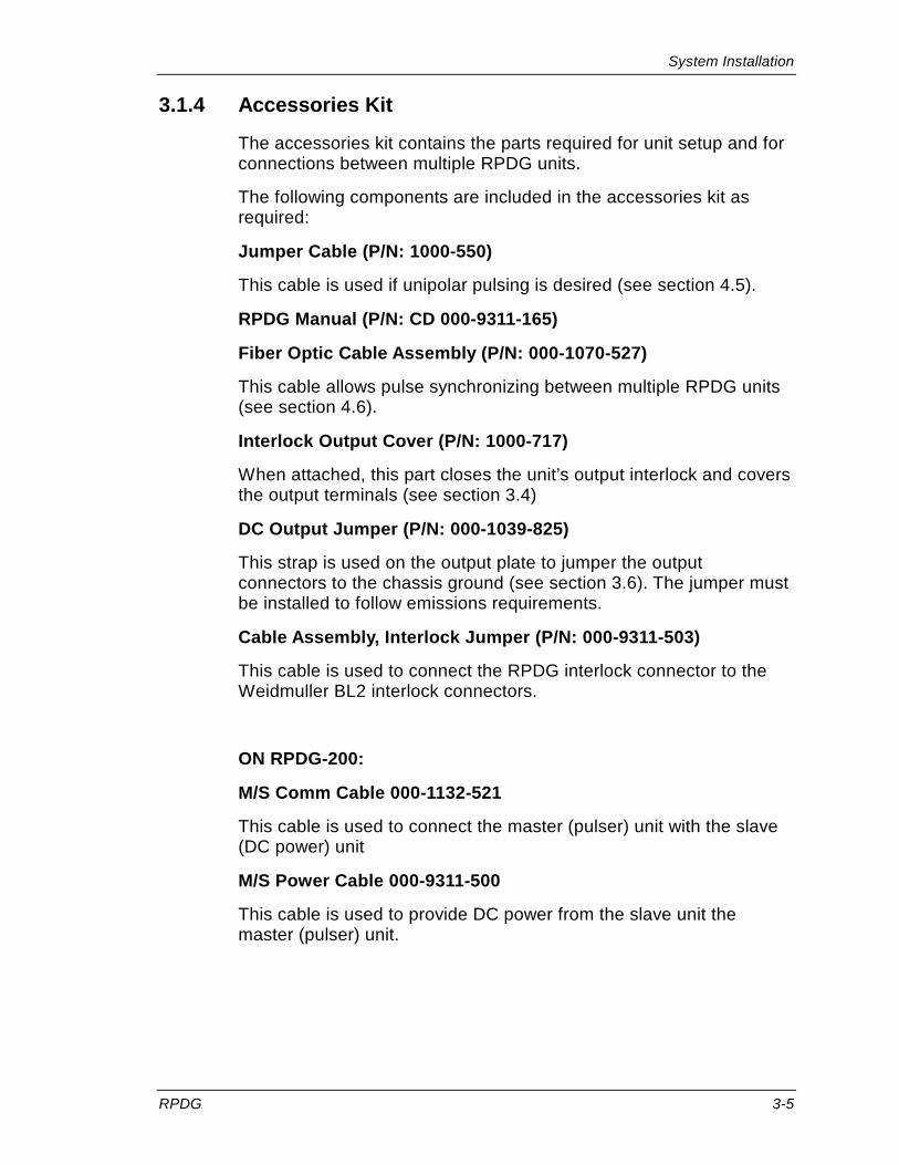
3.1.4 Accessories Kit
The accessories kit contains the parts required for unit setup and for connections between multiple RPDG units.
The following components are included in the accessories kit as required:
Jumper Cable (P/N: 1000-550)
This cable is used if unipolar pulsing is desired (see section 4.5).
RPDG Manual (P/N: CD 000-9311-165)
Fiber Optic Cable Assembly (P/N: 000-1070-527)
This cable allows pulse synchronizing between multiple RPDG units (see section 4.6).
Interlock Output Cover (P/N: 1000-717)
When attached, this part closes the unit’s output interlock and covers the output terminals (see section 3.4)
DC Output Jumper (P/N: 000-1039-825)
This strap is used on the output plate to jumper the output connectors to the chassis ground (see section 3.6). The jumper must be installed to follow emissions requirements.
Cable Assembly, Interlock Jumper (P/N: 000-9311-503)
This cable is used to connect the RPDG interlock connector to the Weidmuller BL2 interlock connectors.
ON RPDG-200:
M/S Comm Cable 000-1132-521
This cable is used to connect the master (pulser) unit with the slave (DC power) unit
M/S Power Cable 000-9311-500
This cable is used to provide DC power from the slave unit the master (pulser) unit.

System Installation
3-6 RPDG
3.2 Preparing for Operation Before you apply power to the RPDG, you need to prepare your system for operation. This preparation includes setting up the remote port, checking the input power capacity, connecting the safety interlock and Master/Slave synch interface(s), when applicable, and connecting the DC output and the AC input. Power should be applied only after these steps have been completed.
Make certain that the AC input power is not connected before following this procedure.
3.2.1 Configuring the Serial Remote Control Port
Default DIP and Serial Mode Selector Switch Settings
The configuration of the serial interface port is determined by the setting of a 12-way DIP switch (S1) and a small selector switch (S2) located on the control board and accessible through the rear panel fan opening (see section 4.10.1). Unless otherwise specified, this DIP switch and small selector switch have been factory-configured as follows:
S1.1-S1.4 ON: RS-422 address=0 S1.5, S1.6 ON: No parity S1.7 ON: 1 stop bit S1.8 OFF: 8 data bits S1.9 ON, S1.10 OFF, S1.11 OFF:
9600 Baud
S1.12 ON: CTS control disabled S2: Set for RS-232 (to the right as viewed through
the fan)
If the settings are not correct, refer to section 4.10.1 for configuration information.
For information on serial cables, see section 4.11.1.

System Installation
RPDG 3-7
3.3 Safety Interlocks The RPDG is equipped with an interlock scheme that, when properly employed, protects the operator from personal injury due to high voltage. If the interlock chain is “broken,” the input AC contactors will open in the unit. If more than one RPDG is being used, all units may share the same interlock chain.
All interlocks internal to each unit are normally closed. They are coupled to the external interlock chain via the two-pin connector on the back. The voltage between the 2 terminals of the Interlock Connector is 24 VDC nominal. There must be closure (a short) between the connector pins to satisfy the interlock.
If the top cover or output connector cover is removed from any unit, all input AC contactors will open in the RPDG interlock chain.
The user can add interlocks, such as those connected to the plasma chamber, by wiring the appropriate contacts into the interlock daisy chain.
System Installation
3-8 RPDG
3.4 Rack Installation To ensure proper operation of the RPDG, it is important to provide correct mechanical support and airflow within a rack installation.
This section briefly discusses airflow and mounting requirements.
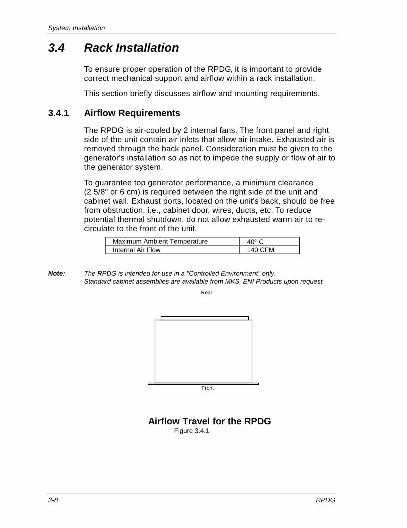
3.4.1 Airflow Requirements
The RPDG is air-cooled by 2 internal fans. The front panel and right side of the unit contain air inlets that allow air intake. Exhausted air is removed through the back panel. Consideration must be given to the generator's installation so as not to impede the supply or flow of air to the generator system.
To guarantee top generator performance, a minimum clearance (2 5/8" or 6 cm) is required between the right side of the unit and cabinet wall. Exhaust ports, located on the unit's back, should be free from obstruction, i.e., cabinet door, wires, ducts, etc. To reduce potential thermal shutdown, do not allow exhausted warm air to re-circulate to the front of the unit.
Maximum Ambient Temperature 40° C Internal Air Flow 140 CFM
Note: The RPDG is intended for use in a "Controlled Environment" only.
Standard cabinet assemblies are available from MKS, ENI Products upon request.
Front
Rear
Airflow Travel for the RPDG
Figure 3.4.1

System Installation
RPDG 3-9
3.4.2 Installation With and Without Slides
For rack-mounting, optional EIA rack slides are available from MKS, ENI Products.
3.4.3 Synchronized Units, Rack Installation
The length of the synchronizing fiber optic cable assembly dictates the proximity of multiple RPDG units acting as a group. It is recommended that rack-installed units be positioned directly above/below each other.
Special lengths are available upon request.

System Installation
3-10 RPDG
3.5 Power Requirements and Installation
The RPDG produces potentially lethal high voltage and current energy. You must gain a thorough understanding of this manual before attempting to hook this unit up to any system.
Note: In the text that follows, a minimum power cable temperature rating of 90°C is assumed. Since the units are expected to be installed in stationary racks and permanently wired, this is not considered a situation falling under the requirements of NEC Article 400.
3.5.1 Power Requirements
The factory-set line voltage is indicated on a label attached to the back panel of the generator.
200-208 VAC
If the nominal line voltage required is 200-208 VAC, it will operate over a full ±10% line-voltage range. No voltage selection is required within this range.
The 10 kW unit will draw a maximum of 50 A per phase. Nominal current is 34 A for a 10 kW unit. The 5 kW unit will draw a maximum of 25 A per phase. Nominal current is 15 A for a 5 kW unit.
The RPDG-200A 20 kW system consists of two units: The pulse unit and the DC unit. The AC input current for the pulse unit is less than 6 A at 200 VAC. The smallest wire size for which the AC terminal block is rated is #14AWG (2.0mm2). The AC input current for the DC unit is 75 A at full load and nominal line voltage. The minimum wire size recommended is #4AWG (21mm2). The largest wire size that will fit in the DC unit terminal block is #2AWG 31mm2). If #2AWG is used, a coarse-stranded wire should be chosen.
400 VAC
If the nominal line voltage required is 380-400 VAC, it will operate over a full ±10% line voltage range. No voltage selection is required within this range.
The 10 kW unit will draw a maximum of 25 A per phase. Nominal current is 19 A for a 10 kW unit. The 5 kW unit will draw a maximum of 15 A per phase. Nominal current is 9.5 A for a 5 kW unit.

System Installation
RPDG 3-11
The RPDG-200E 20 kW system consists of two units: The pulse unit and the DC unit. The AC input current for the pulse unit is less than 3 A at 400 VAC. The smallest wire size for which the AC terminal block is rated is #14AWG (2.0mm2). The AC input current for the DC unit is 45 A at full load and nominal line voltage. The minimum wire size recommended is #8AWG (7.6mm2).
480 VAC Note: The 480 VAC units are not rated for use with 480 VAC corner-grounded delta service.
The source must be wye connected to maintain the lines L1, L2 and L3 at 277 VAC per phase to earth ground. The neutral wire does NOT have to be connected to the RPDG system.
If the nominal line voltage required is 480 VAC, the unit or system will operate over the range from 440 VAC to 504 VAC. No voltage selection is required within this range. The 5 kW unit will draw a maximum of 11 A per phase at output rating. The 10 kW unit will draw a maximum of 23 A per phase at output rating. The smallest wire size for which the AC terminal block is rated is #14AWG (2.0mm2). #14AWG is recommended for the 5 kW unit. The minimum wire size recommended for the 10 kW unit is #12AWG (2.9mm2).
The RPDG-200Z 20 kW system consists of two units: The pulse unit and the DC unit. The AC input current for the pulse unit is less than 3 A at 480 VAC. The smallest wire size for which the AC terminal block is rated is #14AWG (2.0mm2). The AC input current for the DC unit is 40 A at full load and nominal line voltage. The minimum wire size recommended is #8AWG (7.6mm2).
3.5.2 AC Mains Installation
The following information pertains to RPDG-200A DC power units. The DC power unit is equipped with a four-position, 115 A terminal block on the rear panel. The following table indicates the wiring scheme.
Wire Connects to terminal marked as: Line 1 L1
Line 2 L2
Line 3 L3
Ground (ground in a circle)
Note: RPDG AC input wiring is not phase sensitive.

System Installation
3-12 RPDG
The following information applies to all RPDG units except the RPDG-200A DC power units. To deliver AC power to the RPDG, a five-connection terminal block is provided on the rear panel. The following diagram indicates the connection scheme.
Wire Connects to terminal marked as: Line 1 L1
Line 2 L2
Line 3 L3
Ground
Neutral N
NOTE: The RPDG is not phase sensitive.
Figure 3.5.2a shows the power connections on the rear of the standard RPDG generator.
Minimum wire size: 12 AWG RPDG AC Power Input Configuration
Figure 3.5.2a
Note: The Neutral terminal connection serves only as a placeholder for 5-wire AC distribution cable. It provides no electrical connection to the unit or other input wires.

System Installation
RPDG 3-13
The RPDG is designed to be field-wired to the local three-phase AC power source in accordance with North American or International wiring codes. It is the customer's responsibility to fully comply with these wiring codes.
NOTE: A 200-208 VAC unit cannot be reconfigured into a 400 VAC unit, and vice versa!
For RPDG-200A System:
RPDG-200A AC Power Input Configuration Figure 3.5.2b
Note: Units wired for 200-208 V, 400 V or 480 VAC cannot be reconfigured to any of the other AC input voltages.

System Installation
3-14 RPDG
CAUTION: The generator may be damaged if it is connected to the wrong supply voltage or the wiring is incorrect. Before applying power, make sure that the input voltage specified on the Input Ratings Label corresponds to the voltage of your system.
WARNING: Personal injury could result if the generator is not properly grounded.
If the main cover of the RPDG has to be removed, disconnect the line cord from the AC power source. Otherwise, personal injury could result.
WARNING: The AC line filters may retain a charge when disconnected from the source. Be certain the unit is discharged before servicing.
Wire terminations should be stripped, bare wire leads. The use of ferrules, pin terminals, etc., is not recommended.
In order to install the AC lines to the RPDG, the Lexan® Terminal Block cover must be removed with a #2 Phillips screwdriver.
Each conductor must then be fed through the appropriate hole in the Lexan® Terminal Block cover as designated by the above table.

System Installation
RPDG 3-15
Insert each conductor into the appropriate terminal and tighten to the following specifications:
System Master Slave Wire
AWG Torque (in.-lb.)
Wire AWG
Torque (in.-lb.)
RPDG-50Z 12 20 N/A
RPDG-50E 12 20 N/A
RPDG-50A 10 20 N/A
RPDG-100Z 10 20 N/A
RPDG-100E 10 20 N/A
RPDG-100A 6 35 N/A
RPDG-200Z 14 20 8 25
RPDG-200E 14 20 8 25
RPDG-200A 14 20 4 45
Re-attach the Lexan® Terminal Block cover and tighten screws to approximately 12 in.-lbs.

System Installation
3-16 RPDG
3.6 DC Connections Between Slave and Master RPDG-200 systems require connection of a DC power cable between the slave and master units. Refer to Figure 3.6 below. The necessary DC cable has Positronics connectors at both ends, and this cable is provided with the system.
RPDG-200 DC Power Interconnect Figure 3.6
Refer to the following section for connection of RG 393 shielded cable from master unit to the plasma chamber load.
System Installation
RPDG 3-17
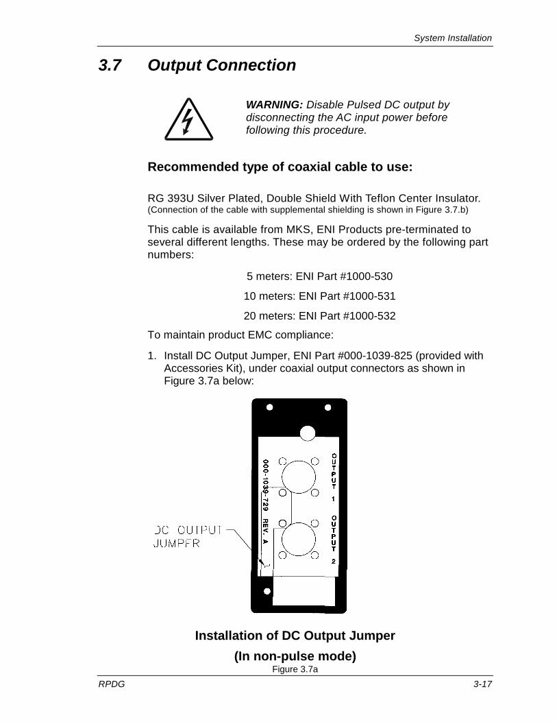
3.7 Output Connection
WARNING: Disable Pulsed DC output by disconnecting the AC input power before following this procedure.
Recommended type of coaxial cable to use:
RG 393U Silver Plated, Double Shield With Teflon Center Insulator. (Connection of the cable with supplemental shielding is shown in Figure 3.7.b)
This cable is available from MKS, ENI Products pre-terminated to several different lengths. These may be ordered by the following part numbers:
5 meters: ENI Part #1000-530
10 meters: ENI Part #1000-531
20 meters: ENI Part #1000-532
To maintain product EMC compliance:
1. Install DC Output Jumper, ENI Part #000-1039-825 (provided with Accessories Kit), under coaxial output connectors as shown in Figure 3.7a below:
Installation of DC Output Jumper (In non-pulse mode)
Figure 3.7a

System Installation
3-18 RPDG
2. Supplemental shielding [in the form of tinned copper braid (85% coverage minimum) or equivalent] is required over the Output cable. At the Rear Panel end of the Output cable, this supplemental shielding shall be grounded to the chassis using the external chassis ground stud provided (see Figure 3.7b).
Detail of Coaxial Cable with supplemental shielding Figure 3.7b
RG-393/U CABLEDOUBLE SHIELDED
TRIAX CABLEWITH SUPPLIMENTAL
SHIELD
Preferred Cable Types Figure 3.7c

System Installation
RPDG 3-19
3.8 Initial Power-up The following items should be checked before applying power for the first time:
1. Guarantee that the AC power input cable is connected to a grounded AC outlet.
2. Make sure that the output power terminations are grounded at the load or at the RPDG.
You may need to go through the checklist below to verify that the unit is ready for power up.
DIP Switches
Interlocks
AC input connection
DC output connection
Moving the breaker to the ON position will energize the supply's control and housekeeping functions. However, the power supply's output remains OFF. The internal microprocessors will execute their diagnostics and when the supply is ready for operation the display will appear similar to the following:
MKS Waiting for COMM.
0.0 0.00 0 VER xxx #.# ######
0.0 0.00 0 121 W 100 K 3000 ns
Progression of Screens
RPDG Power-up Screens with Pulse Enabled Figure 3.8
Note: VER xxx #.# is the version of the software, where xxx is the type and #.# is the version number.
###### is the checksum of that version.

System Installation
3-20 RPDG
This page intentionally left blank.

RPDG Operation
RPDG 4-1
Chapter 4 Table of Contents
Chapter 4 - RPDG Operation ........................................................ 4-4
4.1 Configuring the RPDG ....................................................... 4-4
4.1.1 Available Sources of Control ............................................. 4-4 Front Panel ............................................................. 4-4 ENI Monitor ............................................................. 4-4 Analog User Interface ............................................. 4-5 Profibus User Interface ........................................... 4-5 DeviceNet Interface ................................................ 4-5
4.1.2 Selecting the Appropriate Control Source ......................... 4-6 Selecting the USER or HOST Interface .................. 4-8 Switching Between ENI Monitor and Emulation Monitor .................................................................... 4-9
4.2 Selecting a Mode of Operation ........................................ 4-10
4.3 Arc Control ...................................................................... 4-11 Mechanical Arc Handling Overview ...................... 4-11 Mechanical Arc Handling Type Control Overview . 4-13 Arc Reset Delay Time ........................................... 4-16 Max Arc Count ...................................................... 4-18 Arc Count Clearing ............................................... 4-18 Advanced Arc Handing Features - Resistance Limit Trip ....................................................................... 4-19
4.4 Assymmetric Bipolar Pulsing ........................................... 4-20 Pulse Mode On/Off ............................................... 4-21
4.5 Unipolar Pulsing .............................................................. 4-22
4.6 Using Multiple RPDG Units ............................................. 4-22
4.7 Advanced Features ......................................................... 4-24
4.7.1 Target Life ....................................................................... 4-24
4.7.2 Process Voltage Limit ...................................................... 4-24
4.7.3 Setpoint Deviation (Out of Setpoint) ................................ 4-25
4.7.4 Plasma Lit Detection and Threshold ............................... 4-25
4.7.5 Sputter Yield Voltage ....................................................... 4-25
4.7.6 Plasma Strike Algorithms ................................................ 4-26

RPDG Operation
4-2 RPDG
4.7.7 Pulse Mode Overrider ..................................................... 4-26
4.7.8 RPDG Overvoltage Protection ........................................ 4-26
4.8 Basic Operation Using the Front Panel ........................... 4-27
4.8.9 Front Panel Description................................................... 4-27
4.8.10 Display ............................................................................ 4-27
4.8.11 LEDs ............................................................................... 4-28
4.8.12 Buttons for Normal Operation ......................................... 4-28 DC On button ....................................................... 4-28 Fault Reset Button and LED ................................. 4-29 Regulation Mode Button ....................................... 4-29 Pulse Button ......................................................... 4-29 Run Mode Button ................................................. 4-30 Remote Button ..................................................... 4-31 Lock Button .......................................................... 4-31
4.8.13 Menu Navigation and Operation ..................................... 4-32 Menu Button ......................................................... 4-33 Menu Exit Button .................................................. 4-33 Item Up and Down Buttons .................................. 4-34
4.8.14 Sample Runs .................................................................. 4-35 Constant Output Mode ......................................... 4-35 Run-Time Mode.................................................... 4-36 Joules Mode ......................................................... 4-37 Sequence Mode ................................................... 4-38 Joules Sequence Mode Setting ............................ 4-41 ARC Control ......................................................... 4-43 Asymmetric Bipolar Pulsing Setup ....................... 4-46 Mechanical Arc Detection Setup .......................... 4-46 Target Life Set Up ................................................ 4-47 Setpoint Deviation Setpoint .................................. 4-47
4.9 Basic Operation Using the ENI Monitor .......................... 4-48
4.9.1 Serial Protocol ................................................................. 4-48 Escape from Indefinite Loops ............................... 4-49 Normal Command Data Return ............................ 4-49 Command Transaction Explained ........................ 4-50 Space Characters ................................................. 4-51 Illegal Commands ................................................. 4-51 Leading Zeros and Missing User Arguments ....... 4-51 Special Characters ............................................... 4-51 Link Integrity Checking ^W or LIT ......................... 4-52 XON and XOFF .................................................... 4-52 Link Release Character ........................................ 4-52 Key Level .............................................................. 4-53 Backspace Characters ......................................... 4-53 Power-up Message .............................................. 4-54

RPDG Operation
RPDG 4-3
4.9.2 User Command Set ......................................................... 4-54 Readback Commands .......................................... 4-55 Direct Control Commands .................................... 4-61 Level A Extra Commands ..................................... 4-67
4.9.3 Sample Run Using the Remote Mode ............................. 4-71 Constant Output Mode ......................................... 4-71 Run-Time Mode .................................................... 4-72 Joules Mode ......................................................... 4-73
4.10 Serial Remote Control Interface ...................................... 4-74
4.10.1 Hardware Configuration (pin definition) ........................... 4-74 Serial Interface, DIP Switch Settings .................... 4-75 RS-422 Bussing .................................................... 4-78
4.11 Remote Front Panel ........................................................ 4-79
4.11.1 Sample Cables ................................................................ 4-79
4.12 Interface Cards ................................................................ 4-80
4.12.1 Parallel Interface ............................................................. 4-80
4.12.2 Profibus Interface ............................................................ 4-82
4.12.3 DeviceNet ........................................................................ 4-82

RPDG Operation
4-4 RPDG
Chapter 4 - RPDG Operation 4.1 Configuring the RPDG
4.1.1 Available Sources of Control
The RPDG generator can be controlled from various control sources.
Front Panel
RPDG units are generally shipped with a full-function front panel. This allows total access to the advanced features of the RPDG. Alternatively, if the user intends to operate from either Host port (i.e., a Monitor) or User (hardware) control port, a Master unit may have a blank front panel.
A remote front panel may be used in place of the built-in front panel and offers all of the same controls, readouts, and capabilities.
Slave units have a simple, status-only front panel, with no control capability, aside from the AC mains circuit breaker.
ENI Monitor
The first and more powerful of two "Host Remote interfaces is the ENI Monitor. The ENI Monitor is an MKS, ENI Products proprietary serial protocol that can operate over RS-232 or on a multi-dropped RS-422 network. The ENI Monitor allows total access to the RPDG's advanced features. Refer to section 4.10 for details on the serial interfaces.
RPDG Operation
RPDG 4-5
NOTE: Features described immediately below are included in specific models only, according to customer requirements. These optional features are further described in separate files included within this manual.
Analog User Interface
This simple hardware interface provides on/off and output-level control and readbacks. It uses analog and digital I/O lines in a 25-pin D-sub connector to control the RPDG. It allows no access to the advanced features of the RPDG.
Profibus User Interface
Certain RPDG units are equipped with Profibus user interface. This interface is based on RS-485 physical layer and features excellent error correction capabilities and high data transfer rates as defined by the Profibus trade organization. Refer to the Profibus User Manual (which is included on the CD version of OPT and RPDG manuals) for specifics of this interface.
DeviceNet Interface
The DeviceNet™ interface is a powerful host interface with properties completely defined by the Open DeviceNet™ Vendors Association (ODVA). The MAC ID and baud rate for each power supply system must be set before beginning control through DeviceNet™.
The DeviceNet™ interface board assembly also has some analog control features that are described in a separate manual

RPDG Operation
4-6 RPDG
4.1.2 Selecting the Appropriate Control Source
The first question that must be answered when configuring the RPDG is, "What is the control source?" The possible control sources have been explained above. We will assume that the RPDG we are configuring contains a full-function front panel. The following decisions must be made before the generator can be configured for operation:
• Whether to control locally using the front panel or remotely using the interfaces.
• If remotely, whether to use the USER (hardware) interface or HOST (serial) interface, or MIXED MODE (a combination of both).
The local/remote selection can be made one of two ways. We can press the Local/Remote Button on the front panel or we can issue a command through the remote serial interface. The diagram below illustrates the results of our selection.
REMF (Local)
REME (Remote)
REM1
REM0
Front Panel
Host Interface (ENI or EMULATION Monitor Port)
User Interface (ANALOG or DIGITAL Interface Board)
RPDG-100
REM Tree Figure 4.1.2a

RPDG Operation
RPDG 4-7
The REMx command is used to transfer control of the RPDG between the front panel, the ENI Monitor, and the interface board. Issuing the REME or REMF command via the remote interface is exactly the same as pressing the Local/Remote Button.
Action Result Press Local/Remote Button. LED in button ON; Remote has control.
Press Local/Remote Button. LED in button OFF; Front Panel has control.
Enter command REME from ENI Monitor.
Remote has control; LOCAL/REMOTE LED goes ON.
Enter command REMF from ENI Monitor.
Front Panel has control; LOCAL/REMOTE LED goes OFF.
Local/Remote Selection Table 4.1.2a
The remaining REMx commands determine which parameters are controlled by the USER and which the HOST controls. Table 4.1.2b describes these commands.
Command Result REM0 Transfers ALL control from the ENI Monitor to the Interface board.
REM1 Transfers ALL control from the Interface board to the ENI Monitor.
REM2 Transfers DC On/Off control from the ENI Monitor to the Interface board.
REM3 Transfers DC On/Off control from the Interface board to the ENI Monitor.
REM4 Transfers Output Level control from the ENI Monitor to the Interface board.
REM5 Transfers Output Level control from the Interface board to the ENI Monitor.
REM6* Transfers Regulation Mode control from the ENI/EMULATION Monitor to the Interface board.
REM7* Transfers Regulation Mode control from the Interface board to the ENI/EMULATION Monitor.
REM8* Transfers Ramp time control from the ENI/EMULATION Monitor to the Interface board.
REM9* Transfers Ramp time control from the Interface board to the ENI/EMULATION Monitor.
REMA* Transfers Target Number control from the ENI/EMULATION Monitor to the Interface board.
REMB* Transfers Target Number control from the Interface board to the ENI/EMULATION Monitor.
REMC Transfers Pulse On/Off control from the ENI Monitor to the Interface board.
REMD Transfers Pulse On/Off control from the Interface board to the ENI Monitor. *Only available with Profibus and DeviceNet™.
REMx Commands Table 4.1.2b

RPDG Operation
4-8 RPDG
Selecting the USER or HOST Interface
The USER refers to a hardware interface board that provides remote control. The HOST refers to a serial interface that provides remote control. This choice can be made from the front panel using the Setup/Misc. Menu. In addition, the choice can be made with the REM0 and REM1 commands on the ENI Monitor or the various "S" commands on the Emulation Monitor. The effects of these commands can be seen in Table 4.1.2c.
Control Parameter
Control to Front Panel
Control to Remote USER
Control to Remote HOST
Monitor Type
ENI Emulation ENI Emulation ENI Emulation
ALL REMF S9 REM0 REM1 S8
Output On/Off REM2 SE REM3 SF
Output Set Point
REM4 SA REM5 SB
Regulation Mode*
REM6 SA REM7 SB
Ramp Time* REM8 SC REM9 SD
Target Number*
REMA REMB
Pulse Mode On/Off
REMC REMD
*Only available with Profibus and DeviceNet™.
USER/HOST Control Commands Table 4.1.2c
The following drawing illustrates the effect of the various REMx commands. When the HOST controls some parameters and the USER controls others, we say the system is under Mixed-Mode Control.
Mixed-mode control allows some parameters to be controlled from the Hardware Interface, and the remaining parameters to be controlled from the Monitor. Refer to Figure 4.1.2b. This figure can be seen as a detailed view of Figure 4.1.2a. In Figure 4.1.2a, the Host/User switch applies to all control parameters. Figure 4.1.2b shows how the Host/User switch can be set for each control parameter individually.
A common application is where On/Off control is allocated to the "User" port, and all remaining controls are allocated to the "Host" port.
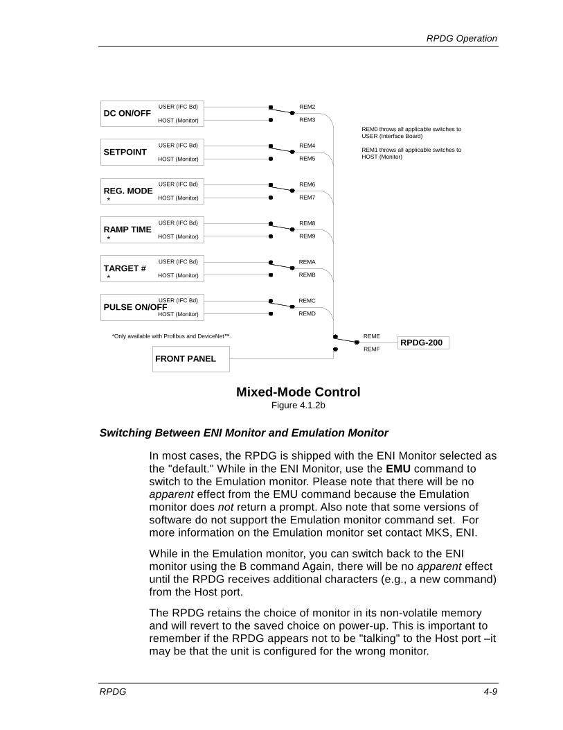
RPDG Operation
RPDG 4-9
DC ON/OFFUSER (IFC Bd)
HOST (Monitor)
SETPOINTUSER (IFC Bd)
HOST (Monitor)
REG. MODEUSER (IFC Bd)
HOST (Monitor)
RAMP TIMEUSER (IFC Bd)
HOST (Monitor)
TARGET #USER (IFC Bd)
HOST (Monitor)
PULSE ON/OFFUSER (IFC Bd)
HOST (Monitor)
FRONT PANEL
REM2
REM3
REM4
REM5
REM6
REM7
REM8
REM9
REMA
REMB
REMC
REMD
REME
REMFRPDG-200
REM0 throws all applicable switches toUSER (Interface Board)
REM1 throws all applicable switches toHOST (Monitor)
*
*
*
*Only available with Profibus and DeviceNet™.
Mixed-Mode Control Figure 4.1.2b
Switching Between ENI Monitor and Emulation Monitor
In most cases, the RPDG is shipped with the ENI Monitor selected as the "default." While in the ENI Monitor, use the EMU command to switch to the Emulation monitor. Please note that there will be no apparent effect from the EMU command because the Emulation monitor does not return a prompt. Also note that some versions of software do not support the Emulation monitor command set. For more information on the Emulation monitor set contact MKS, ENI.
While in the Emulation monitor, you can switch back to the ENI monitor using the B command Again, there will be no apparent effect until the RPDG receives additional characters (e.g., a new command) from the Host port.
The RPDG retains the choice of monitor in its non-volatile memory and will revert to the saved choice on power-up. This is important to remember if the RPDG appears not to be "talking" to the Host port –it may be that the unit is configured for the wrong monitor.
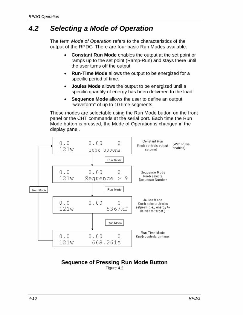
RPDG Operation
4-10 RPDG
4.2 Selecting a Mode of Operation The term Mode of Operation refers to the characteristics of the output of the RPDG. There are four basic Run Modes available:
• Constant Run Mode enables the output at the set point or ramps up to the set point (Ramp-Run) and stays there until the user turns off the output.
• Run-Time Mode allows the output to be energized for a specific period of time.
• Joules Mode allows the output to be energized until a specific quantity of energy has been delivered to the load.
• Sequence Mode allows the user to define an output "waveform" of up to 10 time segments.
These modes are selectable using the Run Mode button on the front panel or the CHT commands at the serial port. Each time the Run Mode button is pressed, the Mode of Operation is changed in the display panel.
Sequence of Pressing Run Mode Button Figure 4.2
100k 3000ns (With Pulse enabled)

RPDG Operation
RPDG 4-11
4.3 Arc Control
Mechanical Arc Handling Overview
The RPDG family of Pulsed DC generators features Mechanical Arc detection in order to extinguish any arcs not alleviated by their asymmetric bipolar pulsed output.
Mechanical Arc Handling, in general, looks for the output voltage to fall below a threshold (typically 100V), when it should not be below that threshold, and when it does, a Mechanical Arc is declared and appropriate action is taken.
In order for the system to detect and act on the Mechanical Arc indication the following conditions must be satisfied:
1. Mechanical Arc Sense has to be enabled in the Software (for example via the “MCA” command)
2. The output voltage has to have gone above the software threshold (typically 120V, as set by the “MAT” command)
3. The Mechanical Arc sense indication has to exist at the time the system senses for it
a. Currently this is sensed just before each positive bias swing (see Figure 4.3a)
4. The output voltage is below the Hardware threshold (typically 100V as set by the factory)
5. In most Mechanical Arc handling modes the following also has to be true, these can be configured depending on the Mechanical Arc handling mode selected (for example via the “MHT” command):
a. The indication has to have been clear for 1 Pulse cycle since the last indication
b. The indication has to have been clear for 1 Pulse cycle since DC was turned On, or after an Arc Reset Delay was performed
c. The indication needs have existed for 2 detection cycles
On detection of a Mechanical Arc the following steps are done (as configured by the Mechanical Arc handling mode):
1. The DC output is turned off for a specified period of time
2. The Positive Bias is applied for a specified period of time
3. After a specified period of time the DC is turned back on

RPDG Operation
4-12 RPDG
Even when Pulse Mode is turned off, the Mechanical Arc Sense is only done at the time just before the positive bias swing would occur. Hence, you want to have the Frequency set to the Maximum Frequency for fastest detection of a Mechanical Arc, when Pulse Mode is off
Since the Mechanical Arc Sense time is based on the frequency, the fastest detection will occur with faster pulse frequencies.
Frequency
Pulse Width Pulse Width
Time that theSwitch is in thePositive/shortingMode
Mechanical ArcSensed
Mechanical ArcSensed
Typically, IfStill PresentHere, thenMech Arc FaultDeclared
Mechanical Arc Sense Figure 4.3a
The energy delivered to the arc is naturally limited because, in the negative bias direction, the RPDG acts as a constant current source. While an arc is occurring, a unit seeks only to maintain its output current level and, with the low-output voltage caused by the arc, an incredibly small amount of energy is delivered to the chamber.
It is highly recommended to use Mechanical Arc detection in all RPDG applications, as it is the fastest and most effective means of extinguishing an arc; however, the customer may disable it if desired.
Parameter ENI Monitor Command Meaning, RPDG Menu Mechanical Arc Detect MCA=<0,1> MCA=1, On
MCA=0, Off

RPDG Operation
RPDG 4-13
Turning the Pulse Mode from Pulse On Pulse Off, Turns the Mechanical Arc ON, and Sets the Pulse Frequency to maximum. Turning the Pulse Mode from Pulse Off Pulse On, Restores the State of the Mechanical Arc to what it was at the On Off Transition, and restores the Frequency as well.
Mechanical Arc Handling Type Control Overview
The Mechanical Arc Handling can be configured to one of five different modes (See Figure 4.3b):
Default/Original Mode (MHT=0):
In the Default/Original mode, on detection of a Mechanical Arc (requires 2 cycles in a row), the positive bias is applied for 250 uSecs, then the bias is removed, and the system continues to keep DC off until the Hard Arc Reset Delay Time (for example settable via the CAD command) is completed. After the Hard Arc Reset Delay time the DC is turned back on.
Extended Short Mode (MHT=1)
In the Extended Short mode, on detection of a Mechanical (requires 2 cycles in a row), the positive bias is applied for the entire Hard Arc Reset Delay Time. After the Hard Arc Reset Delay time the DC is turned back on.
In addition, any time the Hard Arc Delay is performed for a non-Mechanical Arc (i.e. a Hard Arc or an R-Limit Arc), the positive bias is also applied for the entire Hard Arc Reset Delay.
Hi Speed Mode (MHT=2)
In the Hi speed mode, on detection of a Mechanical Arc (requires 2 cycles in a row), the positive bias is applied for 250 uSecs, then the bias is removed, and DC is turned back on.
Ultra Hi Speed Mode (MHT=3)
In the Ultra Hi speed mode, on detection of a Mechanical Arc (requires only 1 cycle), the positive bias is applied for short predetermined period of time (typically 20 uSecs), then the bias is removed, and DC is turned back on.
In addition, any time the Hard Arc Delay is performed for a non-Mechanical Arc (i.e. a Hard Arc or an R-Limit Arc), the positive bias is also applied for the entire Hard Arc Reset Delay.

RPDG Operation
4-14 RPDG
Programmable Mode (MHT=4)
In the Programmable mode, the different settings can be configured outside of the above listed options. This typically requires a trained application engineer to help dial in the settings correctly.
Original/Default
(MHT=0)
250 uSecs
Arc Reset Delay Time
ExtendedShort
(MHT=1)
Arc Reset Delay Time
250 uSecs
Hi Speed(MHT=2)
Ultra Hi Speed(MHT=3)
20 uSecs
to 160 uSecs*
* - Parital Factory Configuration, and some limits based on other settings
Visual View of the Mechanical Arc Handling Type Settings Figure 4.3b
Parameter ENI Monitor Command Meaning, RPDG Menu Mechanical Arc Handling Type
MHT=<0, 1, 2, 3, 4> MHT=0 (Default) MHT=1 (Extended Short) MHT=2 (Hi Speed) MHT=3 (Ultra Hi Speed) MHT=4 (Program)

RPDG Operation
RPDG 4-15
If Mechanical Arc is disabled, the RPDG will then use the following arc control parameters, which can be set using either the front panel or the ENI Monitor. This feature is the same as the hard arc control in the OPT-200 Optima DC product. Further details on hard arc detection settings are provided in section 4.8.6 under “Arc Control.”
Parameter ENI Monitor Command Meaning, Arc Menu Arc Type
ATY=<0,1,2,3> Type 0 is MIN, 1 is MED, 2 is MAX, 3 is USER
Arc Reset Delay Time (Level A Command)
CAD = <2-255> DELAY Units of 200 µs, min. of 400 µs.
Max Arc Count (Level A Command)
MAA= <0-65535> COUNT 0 to 65000
Arc Parameters Table 4.3

RPDG Operation
4-16 RPDG
Arc Type MIN (0), MED (1) MAX (2) and USER (3)
• MIN or ATY = 0 delivers the lowest amount of energy to the target during an arc. Not typically recommended with an RPDG.
• MAX or ATY = 2 delivers the highest amount of energy to the target during an arc. Typically recommended with an RPDG
• USER or ATY = 3 allows the user to define the DC threshold and Proportional components of arc detection and should not be used without first contacting an MKS, ENI Products applications engineer. The average current delivered during an arc increases as Arc Type is increased (see Figure 4.3c).
Arc Type = MAX
Arc Type = MED
Arc Type = MIN
Arc Duration
Average
Current
Average Current during Arcing Figure 4.3c
Arc Reset Delay Time
This parameter is set to 400 microseconds by default. The default value may be changed by using the Front Panel ARC DETECT/ Delay menu or with the Level A monitor command “CAD”.
In the CAD command, the time is shown in units of 200 microseconds. Thus, a setting of 50 corresponds to 50 times 200 microseconds = 10000 microseconds = 10 milliseconds.
In the Front panel menu, the actual delay time is shown in microseconds. The resolution of the setting is 200 microseconds.
In order to adjust this parameter properly for DC operation, the output voltage and output current of the RPDG should be monitored

RPDG Operation
RPDG 4-17
during arcing conditions. In the first few microseconds after the initial arc, while the RPDG output has been turned off, the output current will be seen discharging toward zero. The arc-reset delay time must be set long enough for the DC output current to decay fully back to zero.
This is illustrated in Figure 4.3d.
Ø
ØMinimum
Delay Time
NominaloutI
Nominal
outV
Arc-Reset Delay Time Figure 4.3d

RPDG Operation
4-18 RPDG
The arc-reset delay should be kept short to minimize the regulation errors induced by arcing. Note that, in order to limit output energy during an arc, the RPDG does not attempt to regulate through an arc. Stated another way, continuous arcing can cause the RPDG to effectively lose regulation of the output (though not in a dangerous way, since the actual output will always be lower than the requested output). By keeping the arc-reset delay to a minimum, the negative effects of arcing on output regulation are minimized.
Max Arc Count
This value can range from 0 to 65000 (Serial port allows to 65535) arcs per run. The value entered here sets the threshold for a fault that can be used to shut down the RPDG. Entering a zero disables this control feature. The value may be changed using the Front Panel ARC DETECT Menu or with the Level A "MAA" monitor command.
Arc Count Clearing
In typical operation the Arc Counts (Hard Arc, Mechanical Arc, and Resistance Limit Trip Arc Counts) are cleared only a DC Off to DC On transition. However, they can be forcibility cleared via the "ACR" monitor command at any time. In addition, the system can be configure to not clear the arc counts on the DC Off to DC On transition, and hence only cleared when explicitly told to clear arc counts. This is done using the Level A "CAC" monitor command.
Parameter ENI Monitor Command
Meaning
Arc Count Explicit Clearing
ACR<0,1,2,3> 0 - Reset All Arc Counts 1 - Hard Arc Count Only 2 - Mechanical Arc Count Only 3 - Resistance Limit Trip Arc Count Only
Arc Count Clearing Control (Level A Command)
CAC=<0|1> 0 - Counts Cleared on DC Off On 1 - Explicit Arc Count Clearing Required

RPDG Operation
RPDG 4-19
Advanced Arc Handing Features - Resistance Limit Trip
Software R-Limit is implemented to allow you to specify a Resistance (Impedance) Value on the output that represents an Arc. When the Resistance (Impedance) on the output goes below this threshold the system detects it, and initiates its Hard Arc Handling; by shutting down the DC Output, and going into the specified Arc Reset Delay time. This value can be set via the front panel (under the Arc Menu) or via the Serial Port (using the SRL=x.xx command). The value is set in 0.01 Ohm increments. The Front Panel allows from 0.00 650.00 Ohms, whereas the Serial Port allows for 0.00 655.35 Ohms. Setting this value to 0.00 Ohms effectively disables the Resistance Limit Trip Sense.
Setting this R-Limit value too close to the operating Resistance (Impedance) might cause initial DC Turn on time issues. This can be handled by a adjusting the initial turn on time delay. The suggested default should allow for an R-limit trip of 50% of the operating Resistance (Impedance) into a nominal Resistive load, on a plasma load this should allow for closer R-limit Trips to the operational Resistance (Impedance). In addition if the system is too sensitive (and changing the R-limit trip is not enough) you can modify the sample filter, which requires multiple of these R-Limit Arcs to be sensed in a row before an R-limit trip is declared. The startup delay (RLC1) and length of time to exist in the situation (RLC2) before declaring the R-Limit arc are configured by the RLC command. Typically these are factory configured, and need not be changed.
R-Limit tripped arcs increment the Hard Arc trip counter, as well as their own R-limit Arc Trip Counter. This allows for diagnostics as to which arcs were captured by the Base/Prop Hard Arc Detection method only, and which were caught by the R-Limit Arc Detection method.
Parameter ENI Monitor Command
Meaning, Arc Menu
SRL SRL=x.xx R-Limit Trip Ohms RLC (Level A Command)
RLC1=x RLC2=x
RLC1 – is the Startup Delay in 11.5 uS Increments RLC2 – is the Number in a row required prior to trip

RPDG Operation
4-20 RPDG
4.4 Assymmetric Bipolar Pulsing The RPDG offers the user control of the bipolar pulse’s frequency and width. The frequency range for pulsing is from 50 to 250 kHz (note there is a 25-125 kHz range as well, selectable with the FHL command). The pulse width can be set anywhere between 0 and 40% of the pulse’s duty cycle measured in nanoseconds.
The RPDG parameters can be set and read back from a full-function front panel or through the serial interface with the following commands:
Parameter Command Description Pulse Mode On/Off PLS = <0,1> PLS = 0 disables Pulse Mode
PLS = 1 enables Pulse Mode Pulse Frequency FRQ = <50-250>
<25-125> Sets Pulse Frequency to value between 50 kHz and 250 kHz or between 25 kHz and 125 kHz.
Pulse Width PWF = <496-8016> Note: For 25-125 range, it is 576-16000.
Sets Pulse Width to a value between 496 ns and 8016 ns or between 576 ns and 1600 ns. Note that pulse width is limited to a value no larger than 40% of the duty cycle by the controller. If too great a value is entered, the closest valid value is used and read back.
Frequency Range Selection (Level A Command)
FHL=<0,1> FHL=0 sets the system to the 50-250 kHz Range FHL=1 Sets the system to the 25-125 kHz Range
Table 4.4
The previous serial commands will function as readback commands when entered with no equals (=) sign and no value, for example, "PLS<CR>."
The pulse width will be maintained if the user changes the pulse frequency with one exception. The RPDG will not allow a pulse width of more than 40% duty cycle and will not reset the width if the frequency is then lowered.

RPDG Operation
RPDG 4-21
Pulse Mode On/Off
Switching the Pulse Mode from ON to OFF causes the following changes:
Frequency = Maximum Frequency
Mech. Arc = ON
Arc Reset Delay = The last Arc Reset Delay when Pulse Mode was OFF
Switching the Pulse Mode from OFF to ON does the following:
Frequency = The last frequency when Pulse Mode was ON.
Mech. Arc = The last mech. arc state when Pulse Mode was ON.
Arc Reset Delay = The last arc reset delay when Pulse Mode was ON.
Pulse Width = The last Pulse Width when Pulse Mode was ON.

RPDG Operation
4-22 RPDG
4.5 Unipolar Pulsing
The RPDG should not be connected to the AC line while performing these changes.
If Unipolar Pulsed DC is desired, the Jumper Cable (P/N: 1000-550) must be connected between E5 and E23 on the section of the 10 k Bias Supply Board located on the top of the Eliminarc® Assembly.
Depending on bias module revision either the two fuses, F1 and F2, or the one fuse, F1, must be removed from the section of the 10k Bias Supply Board located in the bottom, center of the RPDG.
In a RPDG-200 there are typically 2 bias modules and 2 Eliminarc® assemblies, located in the RPDG master box. Both have to be modified to convert the RPDG-200 to unipolar.
Unipolar pulsing is often used for Biasing in Cathodic Arc systems.
4.6 Using Multiple RPDG Units The user may desire more than one RPDG to supply Pulsed DC in some processes. In order to be effective, the bias pulses must be of similar frequency and width and be synchronized. This is typically required in a multi-cathode system, where the RPDG's are driving cathodes that are in close proximity to each other.
When configured as synchronized Pulsed DC generators, in this multi-cathode system, the RPDG units will still maintain individual protection from arcs and overvoltage faults, as well as setpoint and DC On/Off control.
Most RPDG units come equipped to operate in a group of up to three synchronized Pulsed DC supplies (One synch master, and two synch slaves). The setup to tell the RPDG if it is a sync master or sync slave requires use of the either Serial Port using the ENI Monitor to configure the software or it can be accomplished using the front panel (RPG MENU - Sync Mode), in addition to the optical coupling of the multiple units. The serial port control command is the Level A "RMS" command, setting a unit to a "synch slave" is done using the "RMS=1" command, and setting a unit to a "synch master" is done using the "RMS=0" command. Typically the RPDG is shipped as a "synch master".
Fiber Optic Cable Assembly part no. 000-1070-527 is provided as an accessory for this configuration (a 36 inch fiber optic cable). Additional cables or longer lengths can be order. To synchronize the

RPDG Operation
RPDG 4-23
units, one RPDG must be chosen as the synch master (as described above). Connect one Master Out Port (see section 2.7.11) from the "synch master" RPDG to the Slave In (see section 2.7.12) of each RPDG.
The RPDG "synch slaves" will then synchronize with the master RPDG and their pulse frequencies and widths will be identical to the master’s when the sync connection is present via the Fiber Optic Cable. If the Sync Slave does not have an input from the Sync Master, then it defaults to its internally set pulse frequency and width values (changeable via the FRQ and PWF commands). However, the RPDG's can be configured to report and handle this loss of sync in different ways, to handle any application need. The No Sync can be set to be a warning (report only) or as a fault (DC turned Off) or ignored (default). This is done via the Level A "ENS" command (0=ignored, 1=warning, 2=fault). The No Sync is only detected during the DC On time.
When a unit is configured as a "synch slave" then the front panel indicates this by placing an "S" in front of the Frequency and Pulse Width Display on the default screen.
Note: The terms Master and Slave when referring to synchronization have different definitions than in past ENI products. In the past, a master/slave configuration denoted control of all system parameters by one master unit. Currently an RPDG’s operating parameters, with the exception of pulse frequency and width, are determined locally to that unit alone. Each unit also performs its own local arc protection. For the RPDG’s purposes, Master and Slave refer only to the control of pulse frequency and width by one RPDG. This is in regards to synchronization discussions; a master/slave RPDG system exists in the RPDG-200.
An accessory controller is currently available as a special product that will allow for synchronize the pulsing of greater than the normal 3 RPDG generators (up to 14 sync control is available). Please consult MKS, ENI Products if it is necessary to synchronize a large number of RPDG generators.
In addition an accessory controller and specialized RPDG interface cards exist that allow for up to 5 RPDGs to be synchronized to a single cathode connection, making the RPDGs appear to be one larger output unit. Please consult MKS, ENI Products if it is necessary to synchronize a set of RPDG generators in this manner.

RPDG Operation
4-24 RPDG
4.7 Advanced Features The following are a collection of advanced features of the generator.
4.7.1 Target Life One of the eight possible target life counters can be selected to monitor energy delivered to the load. The value in each counter may be adjusted or reset when the target is changed. The target life counters can be set from the front panel or serial interface. If the target function is not required, it can be disabled. Each target life counter is a down count of energy delivered to the load (in kWh). If the counter reaches zero while DC is on, the generator will continue to produce power until DC is turned off.
Note: An option exists to change the target life resolution from 1 kWh to 0.01 kWh.
Parameter ENI Monitor Command Target Menu End of Target Life Control TGE=<0,1> TGE=1, Enable
TGE=0, Disable Selected Active Target TGS=<0..7> Selected Active Target Target Setpoint TGKx=y
x - Target Number 0-7 y - Target Setpoint (0-20000 or 0.00 - 655.35) kWh
Target Life for Selected Target
Target Range Selection (Level A Command)
TLS=<0,1> 0 - 1kWh 1 - 0.01 kWh
4.7.2 Process Voltage Limit Process Voltage limit is a hard fault that is used to check if the Output Voltage is below a threshold for a specified period of time, after we have struck (Lit) the plasma. The Time is configured (using the "PVT" Level A command) from 1 mSecs to 3000 mSecs, the voltage limit is configured (using the "PVV" Level A command) from 100 to 600 Volts, and the fault is enabled or disabled (via the "PVC" Level A command). Then if for any reason the voltage goes below the limit, after plasma is stuck (lit), the fault is declared, and power is shut off.
RPDG Operation
RPDG 4-25
4.7.3 Setpoint Deviation (Out of Setpoint)
Setpoint Deviation is a configurable warning that checks for the setpoint to deviate by more than a defined percentage for longer than a defined time. This can be configured from the front panel (it is located in the Setup/Misc menu), or via the serial port using the SPP (Setpoint Deviation Percentage) and the SPD (Setpoint Deviation Time value) commands. The percentage is set as a value from 0% to 50%, and the time is set with a value from 0(Off) to 100 (1000 mSecs) in 10 mSecs steps. The idea with the Setpoint Deviation is if the system is arcing heavily or some such issue, then the setpoint output will be deviating from the specified setpoint by a value that could be an issue, and we want to know if it occurs
4.7.4 Plasma Lit Detection and Threshold The system monitors the current output of the generator, and using this, it determines if the Plasma has been lit (struck). If the current output is above a threshold (configured using the Level A "PLT" command) then Plasma is assumed to be lit. This lit status can be read back using the "PLL" command.
Until the system determines that the plasma has become lit for the first time, the Hard Arc Counter is not increment, even when a Hard Arc Event is detected and reacted on.
4.7.5 Sputter Yield Voltage
Sputter Yield voltage is a low limit alarm for Joules mode. This establishes the DC voltage output level at which an alarm will be generated if the average DC output is less than at the end of a process run. In order to operate the system must be in Joules Mode, and the Sputter Yield Voltage must be configured (either via the front panel in the Setup/Misc menu or with the "SYV" command). The value is set in volts from 0 to 2000 volts.
When the Joules Run ends, if the average DC Output is less than the specified Sputter Yield Voltage value, the SYV Low Limit fault is displayed.
The average sputter yield voltage during the run can be read back with the "ASV" command. This can be used during a test run to determine where the Low Limit value should be set. Note, this is only active if Joules mode is being run, and a Sputter Yield Voltage value is set.

RPDG Operation
4-26 RPDG
4.7.6 Plasma Strike Algorithms The typical strike algorithm for the generator is to turn on at full strike voltage, and remain there for a period of time, then rollback to a specified value. Typically this period of time at full strike voltage is configured as 6 Seconds. After those 6 seconds, the system attempts to limit the output power to 1024 volts. These settings can be modified at the factory. In addition to the typical full voltage strike algorithm, there exists a strike sweep algorithm control. This algorithm will sweep between a specified voltage, and the full strike voltage, over a period of time. This operation is controlled by the Level A "ISW" command (it can be readback via ISW without the Level A Key). The operation is as follows: The system ramps up from the specified voltage value to the full strike at a defined rate, and remains at full strike voltage until that period of time has passed. It then proceeds to sweep down from full strike until it reaches the defined voltage value. At that point it starts the process over again. The default settings are a sweep down to voltage of 800.0 Volts, and a sweep up period of time of 100 mSecs. These settings can be modified at the factory.
4.7.7 Pulse Mode Overrider The Pulse mode overrider is used to control how pulse mode operates before the system has struck plasma. When the Pulse Mode Overrider is disabled (I.e. "PMO=0") then the pulsing (when pulse is enabled via the "PLS" command) starts as soon as DC Turns on (this is the default). When the Pulse Mode Overrider is enabled (I.e. "PMO=1") then the pulsing (when Pulse mode is on) is held off until the plasma has become lit (value settable via the "PLT" command). This is also present on the front panel and can be controlled there as well.
4.7.8 RPDG Overvoltage Protection Overvoltage is when the output of the RPDG goes above a hardware set voltage level protection. When this occurs the RPDG declares an Overvoltage Fault, disables the Pulse Switch for 250 uSecs, and turns DC Off for the Hard Arc Reset Delay Time (however it does not increment the arc counters). A setting does exist to make the Overvoltage protection only turn off the power for the 250 uSecs, and not go into the Hard Arc Reset Delay time. This can be accomplished via the “FOV” key level A command (FOV=0 is normal operation).

RPDG Operation
RPDG 4-27
4.8 Basic Operation Using the Front Panel
4.8.9 Front Panel Description
This section describes the operation of the RPDG plasma generator from the front panel. The front panel is either an integral part of the generator or is mounted remotely. In either case the operation and controls are the same. It is important to understand the function of each control and readback before attempting operation.
The layout of the display and buttons are shown in the Mounting and Outline Drawings located in the back of this manual.
The display contains two rows of 20 characters and is augmented by six LEDs. Two LEDs, AC ON and DC ON, are positioned to the right of the digitizing knob and the other four are located in four of the buttons, Fault Reset, Pulse, Remote Enable, and Lock.
Eleven buttons and a digitizing knob are provided for normal control and setup of the generator.
4.8.10 Display
The display consists of two lines. The top line displays the measured output of the generator in volts, amps, and watts. The bottom line displays the set point, pulse frequency in kilohertz and pulse width in nanoseconds, when pulse mode is on.
0.0 0.00 0 5000W 100k 3000ns
VOLTS AMPS WATTS
SET POINT FREQ PULSE
Pulse Mode On (Synch Master)
Note: if a "synch slave" then an "S" is inserted in front of the Frequency.
Otherwise, if Pulse mode is off, the status is displayed
0.0 0.00 0 5000W Constant Run
VOLTS AMPS WATTS
SET POINT STATUS
Pulse Mode Off
RPDG Operation
4-28 RPDG
When operating in Pulse Mode, the display normally shows the Frequency and Pulse Width. However, when a generator fault has been detected, this area of the display is used to describe the fault. If more than one fault has been detected, the display will show only one fault. When that fault is cleared, the display will show the next fault (if it still exists). When all faults have been cleared, the display will revert to showing the Frequency and Pulse Width (if Pulse Mode if On). The order in which multiple faults are displayed is dependent on a message list built into the generator software and is not indicative of their importance or order of occurrence.
4.8.11 LEDs
The front panel contains six LEDs. Four of the LEDs are inside the Fault/Reset, Pulse, Remote Enable, and Lock buttons. The operation of these LEDs is described with each of their accompanying buttons in later sections. The other two LEDs are positioned to the right of the digitizing knob. The top LED, AC ON, will always be illuminated when the generator is switched on. This indicates the presence of AC power. The lower LED indicates that the DC output of the generator is on.
4.8.12 Buttons for Normal Operation
Six buttons are used for normal control of the RPDG. These buttons allow control of the following functions:
• DC Output On/Off • Fault Reset • Reg Mode (e.g. volts, amps, watts) • Run Mode (e.g. Joules, Sequence, Time, Constant Run) • Remote • Front Panel Lock • Pulse (Enable, Disable)
DC On button
This button controls the output of the generator.
When the LED is on, the generator begins regulating according to the presently selected regulation mode with timing as prescribed by the presently selected Run Mode.
When the output is turned off with this button, the timers used for any of the Run Modes (Sequence, Run-Time, and Joules) are “paused.” The timed mode will be “resumed” when the DC is turned back on.

RPDG Operation
RPDG 4-29
Fault Reset Button and LED
This LED indicates the presence of a fault in the generator. The fault will be listed in the display. When the fault has been removed, this button may be pressed to clear the fault indication and return to normal operation.
The Fault Reset button may also be used to stop the current run. When this button is pressed, the timers used for any of the timed modes (Sequence, Run-Time, and Joules) are reset to zero and the DC output is turned off. This means that a run will start from the beginning when the DC is turned back on.
Regulation Mode Button
The generator has three regulation modes: volts, amps, and watts. Pressing this button allows selection of one of these modes. The character (V, A, W) indicates the selected mode in the set point field of the display.
Each time the regulation mode is changed, the set point field will change to the set point for the new regulation mode. The set point for the new mode can be set by rotating the digitizer knob while the Run Mode is set to "Constant Run." When operating in Pulse Mode, the Constant Run Mode will display the current pulse frequency and pulse width.
Pulse Button
Pressing this button will both enable the Pulse Mode and light the button’s LED or disable the Pulse Mode and extinguish the LED.

RPDG Operation
4-30 RPDG
Run Mode Button
The generator has four run modes: Constant Run, Sequence, Joules, and Run-Time. Pressing this button selects one of these modes. The selected mode is indicated in the status field in the display:
Run Mode
0.0 0.00 0 121w 100k 3000ns
0.0 0.00 0121w Sequence > 9
0.0 0.00 0121w 5367kJ
0.0 0.00 0121w 668.261s
Run Mode
Run Mode
Run Mode
Constant Run
Knob controls output
setpoint
Sequence ModeKnob selects
Sequence Number
Joules ModeKnob selects Joules
setpoint (i.e., energy todeliver to target.)
Run-Time ModeKnob controls on-time.
Sequence of Pressing Run Mode Button Figure 4.8.4
Note: When in Constant Run, and a Ramp Time is set, the Constant Run is replaced with "Ramp Run"
(With Pulse enabled)

RPDG Operation
RPDG 4-31
Constant Run The display shows the frequency and pulse width when Pulse Mode is On. It shows Constant Run if Pulse Mode is Off, and Ramp Time is zero. It shows Ramp Run if Pulse Mode is Off, and Ramp Time is non-zero.
Sequence Mode The display shows the segment number and the time expired or joules delivered in the sequence segment presently running. The set point area of the display shows the present W, A, or V set point for the sequence segment. As the sequence progresses to the next segment, the display changes to represent the new segment. When the display shows a sequence segment number of “F,” the sequence has reached the end with a non-zero set point in timed mode. If the final set point in time mode is zero, the DC output will be turned off. In joules mode the DC output is always turned off when the sequence has completed.
Joules The display shows the Joules delivered. When DC is turned on, the value in the display will increment from zero at a rate according to the energy being delivered.
Run-Time The display shows elapsed time. When DC is turned on, the value in the display will increment from zero.
Remote Button
This button enables and disables remote operation. When lit, the LED indicates that the remote interface is enabled and is now in control of generator operation. In this condition, all of the front panel controls are disabled except for this button and the LOCK button. Pressing the Remote button toggles the Remote Enable State. In some situations, the Remote LED will blink to indicate that communication with the Host via the IFC has been lost.
Lock Button
This button locks and unlocks the digitizer knob and all front panel controls (except the Lock button) so that inadvertent movement will not disturb generator operation. An LED inside the button indicates when the lock function is active. A numeric password can be set through the Host port using the ENI Monitor command PWD. If a password is set, pressing the LOCK button to unlock the front panel will cause the front panel display to prompt the user for the password. After the password is selected using the knob, the LOCK button will unlock the front panel. In addition, the front panel can be completely passive (ignore all controls, and act just as a display). This is done using the Level A Command "FPL=1", it can be disabled (returned to active state) with the "FPL=0".

RPDG Operation
4-32 RPDG
4.8.13 Menu Navigation and Operation
Set up of the advanced functions of the RPDG is accomplished via a system of simple menus. Below is a brief graphical overview of how these menus are laid out. Five menus are presently available:
• Arc Detect • RPG • Sequence • Target Life • Setup/Misc
ARC DETECT RPG MENU SEQUENCE TARGET LIFE SETUP/MISC Hard Arc Count * Pulse Frequency Sequence Number On/Off Tap Setting**** Mechanical Arc Count *****
Pulse Width Level Type Target Number Arc USER Base Term
Max Hard Arcs Mechanical Arc Detect ON/OFF
Number of Points Target Life Remaining
Arc USER Proportional Term
Arc Type Max Pulse Mode ON/OFF Next Sequence Ramp Time Arc-Reset Delay Synch Type Set #0, Set point
Set #0, Time/Joules On/Off Ctrl HOST/USER
Resistance Limit Setpoint
Pulse Mode Overrider
Set #1, Set point Set #1, Time/Joules
Set point Ctrl HOST/USER
Resistance Limit Arcs ******
Mechanical Arc Handling Type
• •
Reg Mode Ctrl HOST/USER
• Set #9, Set point
Ramp Time Ctrl HOST/USER
Set #9, Time/Joules Target No. Ctrl HOST/USER Pulse Mode Control
HOST/USER RS-422 Address** Joules Resolution*** Sputter Yield Voltage Low
Limit Set Point Deviation Time Set Point Deviation
Percentage Software Version*** Software Checksum*** DSP Software Version*** DSP Software Checksum***
* Reading only. Number of Hard Arcs that have occurred during present run.
** Reading only. If DIP switches 1 to 4 are OFF, the RS-422 address set through the serial port will be displayed.
*** Reading only.
**** Tap setting should never be changed from 500 V, for a normal RPDG Unit.
***** Reading only. Number of Mechanical Arcs that have occurred during the present run.
****** Reading only. Number of Resistance Limit Trip Arcs that have occurred during the present run.
Software Menu Overview Figure 4.8.5a
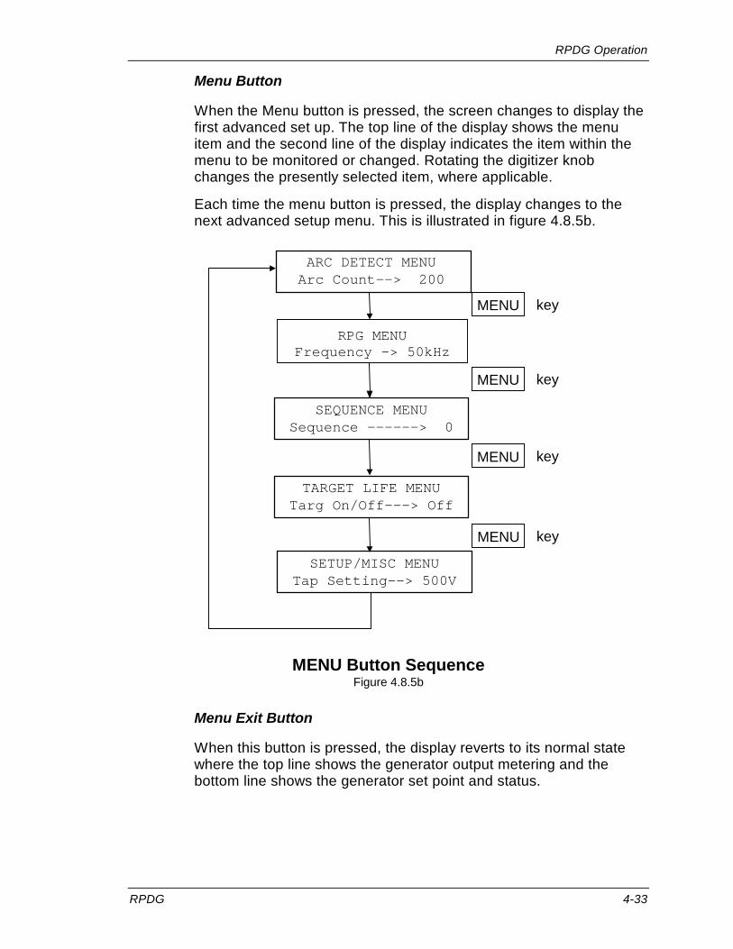
RPDG Operation
RPDG 4-33
Menu Button
When the Menu button is pressed, the screen changes to display the first advanced set up. The top line of the display shows the menu item and the second line of the display indicates the item within the menu to be monitored or changed. Rotating the digitizer knob changes the presently selected item, where applicable.
Each time the menu button is pressed, the display changes to the next advanced setup menu. This is illustrated in figure 4.8.5b.
TARGET LIFE MENU Targ On/Off---> Off
SEQUENCE MENU Sequence ------ > 0
ARC DETECT MENU Arc Count --> 200
SETUP/MISC MENU Tap Setting--> 500V
key MENU
key MENU
key MENU
RPG MENU Frequency -> 50kHz
key MENU
MENU Button Sequence Figure 4.8.5b
Menu Exit Button
When this button is pressed, the display reverts to its normal state where the top line shows the generator output metering and the bottom line shows the generator set point and status.

RPDG Operation
4-34 RPDG
Item Up and Down Buttons
These two buttons allow selection of the item to be changed within each menu. The buttons are only operational when the display is in the menu mode of operation. For example, when the Target Life menu has been selected, the bottom line of the display shows the first of the items within the menu that can be changed:
TARGET LIFE MENU Targ On/Off---> Off
In this example, the target life function is turned on or off by rotating the digitizer knob until the lower right side of the display indicates the desired setting. Pressing the Item Up button will now select the next item in the menu:
TARGET LIFE MENU Targ Select---> 0
In this case, rotation of the digitizer knob will select one of the eight possible target counters to be adjusted. The Target Life menu has one more level that can be accessed by pushing the Item Up button.
When the last item in the menu is reached, further depressions of the Item Up button will have no effect. If all of the necessary changes have been made, the display can be returned to normal operation by pressing the Menu Exit button, or another menu can be selected by pressing the Menu button. The Item Down button allows selection of previous items in a menu. When the first item in a menu has been reached, further depressions of the Item Down button will have no effect.

RPDG Operation
RPDG 4-35
4.8.14 Sample Runs
All examples in this section assume that the RPDG generator has been properly connected to a load of some type.
Constant Output Mode
As mentioned earlier, the Constant Output Mode causes the RPDG to deliver the predetermined output until the operator stops the run. In this example, we will:
• Have the generator raise the power output to 1 kW over a period of 1 second (Ramp up).
• Hold the output power at 1 kW until we stop the run. STEP # Action
1 Turn AC power on using the circuit breakers. 2 Select the Setup/Misc menu with the MENU button. 3 Select Ramp Time with the ITEM UP button. 4 Using the digitizer knob, set ramp time to 1.000 seconds. 5 Press MENU EXIT. 6 Select Constant Run with the RUN MODE button. 7 Select Watts (W) with the REG MODE button. 8 Set the output set point to 1000 with the digitizer knob. 9 Press the ON/OFF button. The power will ramp to 1000 watts and stay there. 10 Press FAULT RESET button to turn the DC output off.
Constant Output Mode Setup Table 4.8.6a
This run will produce a Pulsed DC output represented by Figure 4.8.6a.
Constant Output Mode Figure 4.8.6a

RPDG Operation
4-36 RPDG
Run-Time Mode
The Run-Time Mode allows the DC output to be set to a specific output level and held for a specific length of time. In this example we will:
• Increase the power output to 1 kW over 100 milliseconds (Ramp up).
• Hold the output at 1 kW until 1.2 seconds have elapsed overall. • Drop the output to 0 W.
STEP # Action 1 Turn AC power on using the circuit breakers. 2 Select the Setup/Misc menu with the MENU button. 3 Select Ramp Time with the ITEM UP button. 4 Using the digitizer knob, set ramp time to 0.100 seconds. 5 Press MENU EXIT. 6 Select Run Time with the RUN MODE button. 7 Using the digitizer knob, set run time to 1.100 seconds. 8 Select Watts (W) with the REG MODE button. 9 Set the output set point to 1000 with the digitizer knob. 10 Press the ON/OFF button; the power will ramp to 1000 watts in 0.2
seconds and stay there for 1 second and then drop to 0.
Run Time Mode Setup Table 4.8.6b
The output of this run is illustrated in Figure 4.8.6b
Run Time Mode Figure 4.8.6b

RPDG Operation
RPDG 4-37
Joules Mode
The Joules Mode allows the user to select an output level and hold that level until the desired number of Joules has been delivered to the target. In this example we will:
• Increase the output current to 10 A over a 500 millisecond period (Ramp up).
• Leave the output at 10 A until 4500 kJ have been delivered to the load. • Reduce the output current to 0 A.
STEP # Action 1 Turn AC power on using the circuit breakers. 2 Select the Setup/Misc menu with the MENU button. 3 Select Ramp Time with the ITEM UP button. 4 Using the digitizer knob, set ramp time to 0.500 seconds. 5 Press MENU EXIT. 6 Select Joules Mode with the RUN MODE button. 7 Using the digitizer knob, set 4500 kJ as the end value. 8 Select amps (A) with the REG MODE button. 9 Set the output set point to 10.00 with the digitizer knob. 10 Press the ON/OFF button; the power will ramp to 10 amps and
stay there until 4500 kJ of energy have been delivered to the load. It will then drop to 0.
Joules Mode Setup Table 4.8.6c
The output of this run is illustrated in Figure 4.8.6c
Constant Output and Joules Mode Figure 4.8.6c

RPDG Operation
4-38 RPDG
Sequence Mode
The Sequence Mode allows the user to vary the output of the generator over time. A pattern, or “waveform,” that represents the DC output can be defined and then applied to the load automatically. In this example we will:
• Increase the power to 100 watts over 5.0 seconds and hold it there for another 5 seconds.
• Increase the power to 300 watts over 2.0 seconds and hold it there for 13.0 seconds.
• Increase the power to 500 watts over 3.0 seconds and hold it there for 12.0 seconds.
• Decrease the power to 0 watts over 10.0 seconds and stop the run.
The output of this run is illustrated in Figure 4.8.6d.
Sequence Mode Output Figure 4.8.6d
For illustration purposes, we will break the run into two sequences and chain them together. In order to properly plan a sequence mode run, a Sequence Mode Planning Chart should be completed. Completing this chart prior to programming the generator will prevent missed steps and the need to reprogram. A blank planning chart is provided at the end of this section for your convenience. Figure 4.8.6e is an example of the planning chart that will produce the above results.
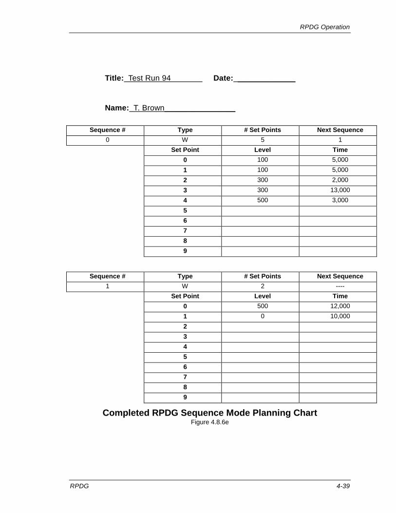
RPDG Operation
RPDG 4-39
Title: Test Run 94 Date: _____________
Name: T. Brown________________
Sequence # Type # Set Points Next Sequence 0 W 5 1 Set Point Level Time 0 100 5,000 1 100 5,000 2 300 2,000 3 300 13,000 4 500 3,000 5 6 7 8 9
Sequence # Type # Set Points Next Sequence
1 W 2 ---- Set Point Level Time 0 500 12,000 1 0 10,000 2 3 4 5 6 7 8 9
Completed RPDG Sequence Mode Planning Chart Figure 4.8.6e

RPDG Operation
4-40 RPDG
STEP # Action 1 Turn AC power on using the circuit breakers. 2 Select the Sequence menu with the MENU button. 3 Set Sequence # to 0 with Digitizer Knobs. 4 Press MENU ITEM up. 5 Select "W" with the digitizer knob. 6 Press MENU ITEM up. 7 Set # of Set Points to 5 with Digitizer Knob. 8 Press MENU ITEM up. 9 Set Next Sequence to 1 with Digitizer Knob. 10 Press MENU ITEM up. 11 Set "Set Point 0" to 100 with Digitizer Knob. 12 Press MENU ITEM up. 13 Set "Time" to 5.000 with Digitizer Knob. 14 Press MENU ITEM up. 15 Set "Set Point 1" to 100. 16 Press MENU ITEM up. 17 Set "Time" to 5.000. 18 Press MENU ITEM up. 19 Set "Set Point 2" to 300. 20 Press MENU ITEM up. 21 Set Time to 2.000. 22 Press MENU ITEM up. 23 Set "Set Point 3" to 300. 24 Press MENU ITEM up. 25 Set Time to 13.000. 26 Press MENU ITEM up. 27 Set "Set Point 4" to 500. 28 Set Time to 3.000. 29 Press MENU EXIT. 30 Select Sequence menu with the MENU button. 31 Set Sequence # to 1. 32 Press MENU ITEM up. 33 Select "W" with the digitizer knob.
Sequence Mode Setup Table 4.8.6d

RPDG Operation
RPDG 4-41
STEP # Action
34 Press MENU ITEM up. 35 Set # of Set Points to 2 with Digitizer Knob. 36 Press MENU ITEM up. 37 Set Next Sequence to NONE with Digitizer Knob. 38 Press MENU ITEM up. 39 Set "Set Point 0" to 500 with Digitizer Knob. 40 Press MENU ITEM up. 41 Set "Time" to 12.000 with Digitizer Knob. 42 Press MENU ITEM up. 43 Set "Set Point 1" to 0 with Digitizer Knob. 44 Press MENU ITEM up. 45 Set "Time" to 10.000 with Digitizer Knob. 46 Press MENU EXIT. 47 Select Sequence Mode with the RUN MODE button. 48 Select Sequence 0 with the Digitizer Knob. 49 Press ON/OFF Button to start the run.
Sequence Mode Setup Table 4.8.6d, cont’d.
Joules Sequence Mode Setting
The Sequence Mode can be configured to work as an amount of Joules to deliver per sequence step vs. a direct time value. This is selected by choosing the Sequence Leveling type of W (J) or V (J) or A (J) (vs. W/V/A) (as displayed on the Front Panel). When in a Joules Sequence at a change to each step the unit steps the setpoint right to the request setpoint. When the last step of Joules Sequence is completed the DC output is turned off. In each step the unit runs until the request Joules are delivered.
Sequence Mode Advanced Feature
When running a timed style sequence and the last setpoint in the sequence is non-zero, the unit maintains this setpoint until it is commanded off, and displays the sequence step presently at as “F”, until the system is commanded to a DC Off state. When the sequence has reached this “F” point the setpoint can then be externally changed via the serial port command “SQF”.

RPDG Operation
4-42 RPDG
Title: ________________________________ Date: ____________
Name: _______________________________
Sequence # Type # Set Points Next Sequence Set Point Level Time/Joules 0 1 2 3 4 5 6 7 8 9
Sequence # Type # Set Points Next Sequence
Set Point Level Time/Joules 0 1 2 3 4 5 6 7 8 9
RPDG Sequence Mode Planning Chart

RPDG Operation
RPDG 4-43
ARC Control Note: This section applies only when RPDG is operating with Mechanical Arc control
Disabled. When Mechanical Arc control is enabled, this arc handling is a secondary protection mode.
The sample runs that were illustrated above did not take arc control into account. In the real world, this would not be acceptable. We saw earlier how arcing can reduce productivity by contaminating the substrate with particles from the target.
More details on the Arc Control can be found in Section 4.3.
The RPDG contains special circuitry for detection and rapid extinguishing of arcs. Several features and parameters can be controlled via the serial interface and front panel. These settings can help tailor the RPDG’s performance to meet process requirements.
1. Press the Menu Button until the Arc Detect menu is shown. The first item shows the number of Hard Arcs that have occurred since the last RESET.
Note: This menu item is for monitoring purposes only and hence the digitizer will have no effect on the value:
ARC DETECT MENU
Hard Arcs --> 176
2. Press the Item Up Button. This item shows the number of Mechanical Arcs that have occurred since the last RESET.
Note: This menu item is for monitoring purposes only; hence, the digitizer will have no effect on the value.
ARC DETECT MENU
Mech Arcs---> 10
3. Press the Item Up button and turn the Digitizer knob to select a Maximum Hard Arc Count of 1000:
ARC DETECT MENU
Max Hard Arcs--> 1000
4. Press the Item Up Button to monitor the Hard Arc Detection sensitivity setting.
ARC DETECT MENU Type--------> Max

RPDG Operation
4-44 RPDG
Note that there are four available Hard Arc detection settings. Each Hard Arc sensitivity setting has two terms included: a base term that sets sensitivity at low output power, and a proportional term that increases the allowable arc current as the output power is increased. Min, Med and Max are factory-preset values of the constants. User terms can be set through software as explained below:
• Min –Minimum allows the smallest amount of current to pass through an arc before tripping. Base constant is 40 and Proportional is 180.
• Med –Medium allows a larger current before tripping. Base is 64 and Proportional is 220.
• Max –Maximum allows the largest amount of current, which corresponds to 125% or rated load. Base is 255 and Proportional 255 (FF).
• User –allows the user to select the optimum value of both constants.
In process development, the user will wish to observe the behavior of the generator and plasma with the arc control set first to Max, and then reduce to Med or Min, before proceeding to User setting. The User setting is adjustable through the front panel using the Setup/Misc menu or via the UBA (Base Term) and UPA (Proportional Term) command using a terminal connected to the serial port. The other three settings are factory programmed and are not adjustable.
Setting the Hard Arc Base term too low can cause the unit to not be able to turn DC On initially. Care needs to be taken that the Base Term is not set to low.
5. Press the Item Up button and turn the Digitizer knob to select a Hard Arc recovery delay of 400 µs:
ARC DETECT MENU
Delay-----> 400µs
The maximum number of Hard Arcs and Hard Arc recovery delay have been set to 1000 and 400 µs respectively and the Hard Arc Type has been set to "MAX". Press the Menu Exit button to return to normal operating mode or if advance arc feature controls are required, the next two steps explain them.

RPDG Operation
RPDG 4-45
6. Press the Item Up button to go into the advanced Arc Handler Feature, Resistance Limit Setpoint:
ARC DETECT MENU RLimit Setpt-> 0.00
The Resistance Limit setpoint is set in Ohms. Here a value is specified that defines what the measured impedance of the output has to go below, before a Resistance Limit Arc is declared. For example, a value of 0.00 Ohms is basically turning this feature off, where a value of 1.00 says that when the output impedance is calculated as a value <= 1.00 Ohms, then an R-Limit arc is declared. R-Limit Arcs perform the same Arc Reset Delay Time as a Hard Arc, but increment their own counter (see next menu item). For now leave this at 0.00 (disabled)
7. Press the Item Up Button. This item shows the number of Resistance Limit Trip Arcs that have occurred since the last RESET:
Note: This menu item is for monitoring purposes only; hence, the digitizer will have no effect on the value.
ARC DETECT MENU
R Lim Arcs-> 5
Press the Menu Exit button to return to normal operating mode

RPDG Operation
4-46 RPDG
Asymmetric Bipolar Pulsing Setup
The RPDG Menu gives access to all of the bipolar pulsing parameters. The specific values of these parameters are process specific and are usually determined in development stages of a process.
For demonstrative purposes, we will set an RPDG unit to pulse its positive bias voltage at a frequency of 100 kHz with a pulse width of 3056 ns.
STEP # Action 1 With the MENU button, select the RPG menu. 2 Press Item Up button four (4) times to advance to Pulse Mode. 3 Using the digitizer knob, set Pulse Mode to ON. 4 Press Item Down button four (4) times to advance to Frequency. 5 Using the digitizer knob, set Pulse Freq to 100 kHz. 6 Press the Item Up button to advance to Pulse Width. 7 Using the digitizer knob, set Pulse Width to 3056 ns. 8 Press Menu Exit Button.
Pulse Mode Set Up Table 4.8.6e
Mechanical Arc Detection Setup
Another feature of the RPDG is Mechanical Arc detection. The unit is constantly monitoring the DC output voltage and when it drops to a factory-determined amount below the voltage set point, the unit stops all DC going to the output terminal and increments the Mechanical Arc Counter. This feature is accessed through the RPDG Menu and is set using the digitizer knob. More detail on this can be found in Section 4.3.

RPDG Operation
RPDG 4-47
Target Life Set Up
The RPDG has eight Target Life counters (0 thru 7). These counters are used to monitor the usage of various targets and display kilowatt-hours. If we would like to limit Target 2 to 300 kWh, we would proceed as follows:
STEP # Action 1 With the MENU button, select the Target Life menu. 2 Using the digitizer knob, select ON. 3 Press the Item Up Button to advance to Targ Select. 4 Using the digitizer knob, select target 2. 5 Press the Item Up Button to advance to kWh Left. 6 Using the digitizer knob, select 300 kWh. 7 Press Menu Exit Button.
Target Life Set Up Table 4.8.6f
Target 2 has now been set for a maximum of 300 kWh and is the active target counter. As power is delivered to the target, this counter will decrement. When it reaches zero, the EOTL (End of Target Life) fault will be displayed, but the output will not be affected. The process may be stopped and restarted while the EOTL fault is active.
Setpoint Deviation Setpoint
The RPDG allows for a configurable warning that checks for the setpoint to deviate by more than a defined percentage for longer than a defined time to be setup. This is the Setpoint Deviation warning (the Out of Setpoint fault).
If we would like to enable the setpoint deviation to occur if the setpoint is off by 5% of the output for longer than 100 mSecs then we would proceed as follows:
STEP # Action 1 Select the Setup/Misc menu with the MENU button 2 Select Setpoint Deviation with the ITEM UP button 3 Using the digitizer knob, set deviation time to 100 mS 4 Select Setpoint Deviation (Percentage) with the ITEM UP button 5 Using the digitizer knob, set deviation percentage to 5% 6 Press MENU EXIT
Setpoint Deviation Set Up Table 4.5.6g
The Setpoint Deviation has now been setup for a deviation of 5% over a 100 mSec time period. If this occurs then the setpoint deviation (out of setpoint) warning will be displayed.

RPDG Operation
4-48 RPDG
4.9 Basic Operation Using the ENI Monitor We learned earlier in this chapter that the RPDG could be controlled by a remote terminal or computer as well as by the front panel. While the remote operation provides a convenient way to control and monitor operations, the language and communication protocol is very exacting. We will approach remote communications in four steps:
• Serial Protocol • Power-up Message • User Command Set • Sample Runs
4.9.1 Serial Protocol
Data is transferred to and from the RPDG using a simple ASCII protocol. This data can be generated with a basic data terminal or with a PC that is running common communications software such as ProComm™ or CrossTalk™.
Note: Each unit in a master-slave system is equipped with a serial port connector. However in normal use all host communications should be connected to the master unit only. Slave units reject many of the commands. Some may be useful for diagnostic purposes.
The generator uses either of two command sets for serial communication: the ENI monitor or the Emulation monitor. The Emulation monitor recognizes the same commands used by an Advanced Energy® MDX-10™. See section 4.1.2.
All ENI monitor commands are composed of three ASCII characters followed by numbers where applicable, and terminated by a carriage return. Numerical fields will be verified to be certain that the numbers are within a specified range.
All characters sent to the RPDG over the ENI Monitor port are echoed by the RPDG. Thus, if the serial port is being driven by a computer, the computer can verify that the RPDG received the characters. In order to keep communications to a minimum, there are no unprompted responses. The only exception to this is the Power-up Message, which can be suppressed.
Note: Echo of characters can be disabled via the "EKO" command. See Table 4.9.2c for more information. The following assumes that echo is enabled.

RPDG Operation
RPDG 4-49
Upon receipt of a carriage return (0Dh), the controller returns a carriage return and a line feed (0Ah) so that the terminal screen is correctly formatted. In addition, an asterisk “*” (2Ah) is used to indicate that the command has been accepted and executed. If an unrecognized command is received, a question mark “?” (3Fh) and bell character (07h) are returned instead. The response is ordered as follows:
• In the case where a simple three-letter command XYZ <CR> is sent and no specific reply is requested, the response is
X Y Z CR LF *
• In the case where an invalid three-letter command XYZ <CR> is sent, the reply is
X Y Z CR LF BEL ?
Escape from Indefinite Loops
Some commands continue indefinitely. These commands are sent with the character – included after the three letters. The escape character is used to exit from this condition. Upon receipt of the escape character the controller will terminate the loop and respond with the command completion string, LF CR *.
• In the case where a command is sent which allows for the – character, but the – is not sent, the response is of the form:
X Y Z <LF>, <CR>, <Data>, <CR>,<LF>,*
• In the case where a command is sent which allows for the – character, and the – is sent, the response is of the form:
X Y Z - <LF>, [<CR> <Data> loopback to CR]
Send <Escape> to terminate looping back:
Response is <LF>, <CR>,<Escape message>,<LF>,<CR>,*
Normal Command Data Return
Commands that do not have the ability to continue indefinitely, but return data, have a response in the following format:
X Y Z <CR>, <LF>, <Data>, <CR>,<LF>,*

RPDG Operation
4-50 RPDG
Command Transaction Explained
The following diagram describes the command transaction (described in the Normal Command Data Return); this idea can be applied to all other commands:
HOST GENERATORX
X
CharacterEchoed
Y
Y
Z
Z
CharacterEchoed
CharacterEchoed
<CR>
Command Executed
<CR>
<LF>
<Data>
<CR>
<LF>
*
Example of a Command Transaction Figure 4.9.1a

RPDG Operation
RPDG 4-51
Space Characters
Commands sent to the RPDG may include space characters (20h) as desired. The RPDG will echo such characters back to the sender, but will otherwise ignore them. Space characters are not saved in the software's internal receive buffer.
Illegal Commands
Unrecognized commands or illegal parameters are ignored and enunciated by the return of a question mark character and a bell character. The same response occurs if the limits of the line buffer are exceeded (16 characters). Note that a carriage return on its own is a valid command that does nothing.
Leading Zeros and Missing User Arguments
The numerical portion of a command need not contain leading zeros, although leading zeros will be echoed if they are sent. Numbers sent to the terminal from the RPDG will have leading zeroes suppressed. If a required user argument is omitted, the RPDG will assume a value of zero for that argument.
Special Characters
Five characters have a special purpose, and are the only characters not echoed on the serial link.
ESC The ESC character (1Bh) allows the operator to break out of
continuous loops that were initiated with a dash character in the command line.
control-W ∧W (17h) is used to maintain link integrity. control-S ∧S (XOFF, 13h) is used to suspend serial output from the RPDG. control-Q ∧Q (XON, 11h) is used to resume serial output (from the RPDG) that
was suspended via XOFF. !! Two consecutive exclamation marks (21h) received in a row will
cause an immediate release of the RS-422 buffer.

RPDG Operation
4-52 RPDG
Link Integrity Checking ^W or LIT
The generator has a built-in function that detects the loss of the RS-232/422 serial link on the digital interface. If the RS-232/422 link seems to have been broken, the generator will shut off the DC power and not allow the DC to be turned back on until the link is restored.
The generator always defaults at power-on with this function disabled. To enable the function, a [^W] must be sent from the host. Once the host initiates this function, the generator will expect to see [^W] from the host on a continuous basis. If another [^W] is not received within one second of the last one sent, the generator will assume the host is no longer connected and will produce a link integrity error, thereby shutting off the DC power.
Link integrity checking may be enabled by the host using the command LIT=1, and disabled by the command LIT=0. The LIT command is also described in the Direct Control Commands section to follow.
XON and XOFF
When XOFF is received (control-S), transmission of serial data is halted. When XON is received (control-Q), transmission of serial data is restarted.
Link Release Character
When two exclamation marks are received immediately after one another (i.e., with no intervening characters), the controller immediately tri-states the RS-422 output. The purpose of this is to avoid collisions on the RS-422 bus if multiple controllers are being used. The correct way to switch from one controller to another is to execute a link release (!!) and then use the IDE command to select the new controller. The IDE command will work on its own, but will occasionally suffer from a collision when the old controller does not release before the new controller takes over.

RPDG Operation
RPDG 4-53
Key Level
Each command in the RPDG repertoire is assigned to a specific key level. Most commands used by a customer are at key level zero. This means that they are enabled by default on power-up of the RPDG. Commands in this category include the most basic on/off and control commands, as well as the readback commands, e.g., SPA, SPV, TRG, OFF, CHL, CHT, MVA, MVV, etc.
The CAD and PWD commands are assigned to the next level, key level A. This means that CAD cannot be run immediately after power-up. In order to run CAD, you must first enter the command KEY1234. 1234 is the key code for enabling key level A. The command KEY1234 allows access to all Key level 0 and Key level A commands.
In this document, the key level of each command is identified as either 0 or A. If you attempt to enter a command at an unauthorized access level, the system responds with:
<ACCESS DENIED TO LEVEL x>
In the case where a three letter command is sent without first transmitting the key code for the command, the response is of the form:
X Y Z <LF> <CR> <Key level error message> <LF> <CR> ?
To return to key level 0, send the command KEY0 <CR>.
Backspace Characters
Backspace or delete characters (08h or 7Fh) allow limited editing. When one of these characters is received, the last character in the line buffer is deleted and the following character string is returned. (08h 20h.08h)
BS SP BS
This ensures that a terminal screen backspaces its cursor and removes the last character.

RPDG Operation
4-54 RPDG
Power-up Message Note: If "QUIET" mode has been selected during setup, none of these power-up messages
will appear. The messages appear only if "VERBOSE" mode is in effect.
The normal power-up text is shown below. ASCII control characters are shown in boldface:
NOTE: CR is 0Ah, LF is 0Dh, and BEL is 07h.
CR LF ENI Monitor on. CR LF Power-Up Delay In effect for next 15 seconds.
CR LF BEL *
After the power up delay has elapsed, the RPDG sends the following text. The asterisk enclosed by curly braces is a unique string that the RPDG sends only on power-up. A host computer can use this string to detect and verify power-up of the RPDG.
CR LF Power-Up Delay Complete. CR LF BEL {*}
The messages described in this section are the only cases where the RPDG sends unsolicited characters to the terminal.
4.9.2 User Command Set
RPDG-specific user commands are grouped into three categories:
1. Readback: The Readback commands are known as passive commands. They simply read back a value or status. Consult Appendix B if you are unfamiliar with Hexadecimal notation.
Note: In calibration of the units, each recorded calibration point is the average of five data points. Calibration is controlled to ± 0.1% for values between 10% and 100% of rating. Data variations in the readback commands MVA, MVV, MVW reflect single captures of the data, and hence may vary by more than ± 0.1%.
2. Direct Control: The Direct Control commands can be used to cause an immediate change to the system.
3. Level A Extra: The Level A Extra commands allow the user to set the password and change other settings of the RPDG. Level A commands are typically used in the factory to set up the system.

RPDG Operation
RPDG 4-55
Readback Commands
Command Options Description AMM <-> Display all measured measurements (in the order of
Volts, Amps, Watts). Refer to MVV, MVA, and MVW for notes.
ASV Displays the Average Sputter Voltage calculated in the most recent process run. This value is used to determine SYV faults. It is only valid after a Joules Run.
ATR <-> Displays Hard Arc counter. If the command line includes a dash (-) character, the display is repetitive until an ESCAPE character is entered.
CHK <x-y> CHKx-y (x=start address (hex), y=end address (hex)) This command calculates the checksum of the program memory range specified. This checksum is displayed on the front panel during power-up, and is also located in the Setup/Misc Menu.
DAT Display the factory entered Date of the unit configuration.
DSP <0/1/2> Display the DSP's Checksum and Version information 0 - Show DSP's Checksum and Version 1 - DSP Version 2 - DSP Checksum
ISW Display if the Ignition Sweep Strike Algorithm is Active (1) or not (0).
MTR <-> Displays the Mechanical Arc counter. If the command line includes a dash (-) character, the display is repetitive until an ESCAPE character is entered.
MVA <-> Displays the measured current. The values are displayed with the rated accuracy of the RPDG itself. (See note on p. 4-54.) Current is displayed to two decimal points. Leading zeroes are suppressed.
MVJ <-> Displays remaining measured Joules during a Joules mode run.
MVT <-> Displays remaining measured Time during a Joules mode run.
MVV <-> Displays the measured voltage. The values are displayed with the rated accuracy of the RPDG itself. (See note on p. 4-54.) Voltage is displayed to one decimal point. Leading zeroes are suppressed.
Readback Commands Table 4.9.2a

RPDG Operation
4-56 RPDG
Command Options Description MVW <-> Displays the measured power.
The values are displayed with the rated accuracy of the RPDG itself. (See note on p. 4-54.) Power is displayed to the nearest watt (zero decimal points.) Leading zeroes are suppressed.
NAM Display the factory entered Name of the unit configuration.
PCV <-> Display the Peak Calculated Voltage Value This is a calculated Peak Voltage Value out of the generator, when the generator is pulsing, based on the measured voltage (as seen with the MVV command) and the Frequency and Pulse Width.
PCW <-> Display the Peak Calculated Wattage Value This is a calculated Peak Wattage Value out of the generator, when the generator is pulsing, based on the measured watts (as seen with the MVW command) and the Frequency and Pulse Width.
PLL Display the Plasma Lit Status (0=Un-Lit, 1 = Lit)
PMR Display the Power Module Status for RPDGs This command returns a binary output. As shown at the end of this table.
PNF Display the DC On/Off Status: 0 - DC Off 3 - DC is On
REP System Report Displays certain data for the master; then queries each slave for some of its data and displays the slave data, line by line.
RFV <=/x> When the RFV command is entered with an equals sign after the mnemonic, the RPDG will output a one-line description of each fault that is active at the time. In addition, the RPDG will categorize the fault. When entered without an equals sign, it returns a 16-bit value called the fault vector that is formatted as four hexadecimal digits. When an argument of zero is specified, the main fault vector is returned. If the argument specified is a value from 1 to F, a 16-bit fault vector, relating to bit positions 1 to 15 in the main fault vector is returned, allowing the exact faults to be isolated. See Appendix D for more information on using this command.
Readback Commands, Continued Table 4.9.2a

RPDG Operation
RPDG 4-57
Command Options Description ROT <-/=> Returns the DC output on-time in decimal. If the
command line does not contain an equals sign, the value returned is the on-time, truncated to the nearest hour. If an equals sign appears in the command line, the on-time is shown to the nearest second, with the format shown below: Hhhhhhh.mm.ss If a dash character appears on the command line, the command will repeat continuously, until the Escape key is pressed.
RST Returns the control status of the RPDG. It will display the word LOCAL if front panel control has been selected. Otherwise the display will show whether HOST (serial port) or USER (interface card) has control for each of the following: DC ON-OFF, SETPOINT, REGULATION MODE, RAMP TIME, TARGET NUMBER and PULSE MODE.
RTR <-> Displays the Resistance Limit Trip Arc counter. If the command line includes a dash (-) character, the display is repetitive until an ESCAPE character is entered.
RUT <-/=> Returns the up time of the controller. The value returned increments once per hour. If an equal (=) is typed after RUT, the command will return hours, minutes, and seconds. The data format is exactly the same as for the ROT command. Note that the command will continuously loop if a dash (-) is used. The dash will also work in conjunction with the equals sign.
RVE This command returns the version number of the software. Format is typically: VER XXX #.#.## XXX - is the software indicator The first # is the Major Software Revision The second # is the Minor Software Revision The ### is an adjustment location (typically 000 for released software). The "VER XXX #.#" is also shown on the front panel during power-up, and is located in the Setup/Misc Menu.
SER Display the factory entered Serial Number of the unit configuration.
Readback Commands, Continued Table 4.9.2a
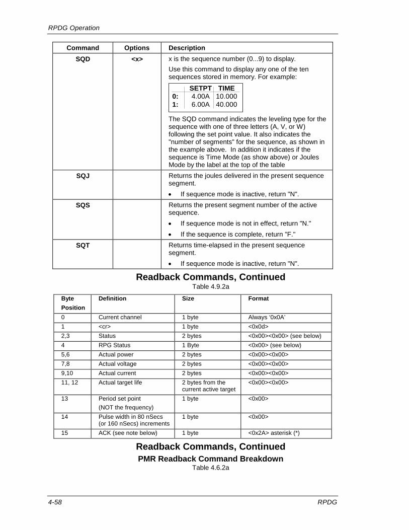
RPDG Operation
4-58 RPDG
Command Options Description SQD <x> x is the sequence number (0...9) to display.
Use this command to display any one of the ten sequences stored in memory. For example:
SETPT TIME0: 4.00A 10.0001: 6.00A 40.000
The SQD command indicates the leveling type for the sequence with one of three letters (A, V, or W) following the set point value. It also indicates the "number of segments" for the sequence, as shown in the example above. In addition it indicates if the sequence is Time Mode (as show above) or Joules Mode by the label at the top of the table
SQJ Returns the joules delivered in the present sequence segment. • If sequence mode is inactive, return "N".
SQS Returns the present segment number of the active sequence. • If sequence mode is not in effect, return "N." • If the sequence is complete, return "F."
SQT Returns time-elapsed in the present sequence segment. • If sequence mode is inactive, return "N".
Readback Commands, Continued Table 4.9.2a
Byte Position
Definition Size Format
0 Current channel 1 byte Always ‘0x0A’ 1 <cr> 1 byte <0x0d> 2,3 Status 2 bytes <0x00><0x00> (see below) 4 RPG Status 1 Byte <0x00> (see below) 5,6 Actual power 2 bytes <0x00><0x00> 7,8 Actual voltage 2 bytes <0x00><0x00> 9,10 Actual current 2 bytes <0x00><0x00> 11, 12 Actual target life 2 bytes from the
current active target <0x00><0x00>
13 Period set point (NOT the frequency)
1 byte <0x00>
14 Pulse width in 80 nSecs (or 160 nSecs) increments
1 byte <0x00>
15 ACK (see note below) 1 byte <0x2A> asterisk (*)
Readback Commands, Continued PMR Readback Command Breakdown
Table 4.6.2a

RPDG Operation
RPDG 4-59
Note: After the ACK at Byte 15, the unit does the normal <CR><LF>'*'.
BIT Definition BIT = 0 BIT = 1 8 (lsb) End of Target Life EOTL No EOTL
9 Joules Setpoint Reached Not Reached Reached
10 Run Time Setpoint Reached Not Reached Reached
11 Plasma Lit Not Lit Lit 12 <Internal Status Bit> Ignore Ignore
13 <Internal Status Bit> Ignore Ignore
14 <Internal Status Bit> Ignore Ignore
15 (msb) SYV Fault No Fault Fault
Readback Commands, Continued PMR Readback Command Status Breakdown (Byte 2)
Table 4.6.2a
BIT Definition BIT = 0 BIT = 1 0 (lsb) <Internal Status Bit> Ignore Ignore
1 Process Voltage Limit No Fault Fault 2 Current Limit In regulation At Current Limit 3 Power Limit In regulation At Power Limit 4 Out of regulation flag In regulation Out of regulation
5 Sense Card Comms No Fault Fault 6 Ramp Setpoint Not Completed Reached
7 (msb) Last Sequence Setpoint Not Reached Reached
Readback Commands, Continued PMR Readback Command Status Breakdown (Byte 3)
Table 4.6.2a
BIT Definition BIT = 0 BIT = 1 0 (lsb) Pulse mode status bit Pulse OFF Pulse ON 1 Mech Arc status bit Mech Arc OFF Mech Arc ON 2 Power Module DC Dc output OFF Dc output ON 3 Volts Mode Not Volts Mode Volts Mode 4 Amps Mode Not Amps Mode Amps Mode 5 Watts Mode Not Watts Mode Watts Mode 6 <Internal Status Bit> Ignore Ignore 7 (msb) <Internal Status Bit> Ignore Ignore
Readback Commands, Continued PMR Readback Command RPG Status Breakdown (Byte 4)
Table 4.6.2a

RPDG Operation
4-60 RPDG
Additional PMR Readback Command PMR Notes: Actual Power is in 1 Watt Increments. Order is MSB (Byte 5), LSB (Byte 6) Actual Voltage is in 0.1 Volt Increments. Order is MSB (Byte 7), LSB (Byte 8) Actual Current is in 0.01 Amp Increments. Order is MSB (Byte 9), LSB (Byte 10) Actual Target life is in either 1 kWh or 0.01 kWh depending on TLS (Target Life
Switch Setting) from the currently active Target Life (Selected Target). Order is MSB (Byte 11), LSB (Byte 12)
Period Setpoint is the number of counts at the selected increment. o Example, if returns 50, at a 50-250 kHz frequency range, that is 50 * 80
nSecs = 4uSec or 250 kHz for the frequency. Pulse Width Increments is dependent on the Pulse frequency range.
o The Selected Increments for Period and Pulse Width is based on the following:
If the range is 50-250 kHz (FHL=0) then the Pulse Width Increment is 80 nSecs.
If the Range is 25-125 kHz (FHL=1) then the Pulse Width Increment is 160 nSecs.

RPDG Operation
RPDG 4-61
Direct Control Commands Note: Some of these commands also have readback capability. In general, the equal option (=) is used to differentiate between reading and writing data. If an equals option is used, it causes a change to the system by writing data.
Consider the following before employing any command:
1. The Controller will respond with a question mark for the following commands when an out-of-range value is specified.
2. In-range values will be responded to with an asterisk (*) when the command has been successfully completed.
Command Option Description ACR <0,1,2,3> Clear Arc Counts
0 - All Arc Counts 1 - Hard Arc Counts 2 - Mechanical Arc Counts 3 - Resistance Limit Trip Arc Counts
ATY <=0,1,2,3> Select the Hard Arc Type. See section 4.3, Arc Control.
B Switches to ENI Monitor serial protocol from the Emulation Monitor. See section 4.6.1.
CHL <=A/V/W/a/v/w> CHL CHL=x Used to set or read the leveling type (regulation mode) of the RPDG. If entered without an equals sign in the command line, the command is used to read the leveling type. The monitor returns V, A, or W, as appropriate. If the command line contains an equals sign, the leveling type is changed according to the character to the right of the equals sign, and the selected set point register becomes the active set point register. If DC output is on, and CHL= is entered with a valid argument, DC output is turned off.
Direct Control Commands Table 4.9.2b

RPDG Operation
4-62 RPDG
Command Options Description CHT <=S/C/ST/SJ/
CT/CJ/T/J> CHT CHT=x Selects or enables or disables the advanced control and shutdown modes.
Argument Constant Joules Run-Timeto CHT Output Sequence Shutdown Shutdown
Command Mode Mode Mode ModeC Y N N NCJ Y N Y NCT Y N N Y
S N Y N NSJ N Y Y NST N Y N Y
J no effect no effect Y NT no effect no effect N Y
Note that the letters C and S are mutually exclusive, as are the letters T and J. The letters C and S determine the output-vs.-time characteristic of the RPDG following the next TRG command: C: Constant-Output mode S: Sequence mode Similarly, the output shutdown mode is selected by the letters J or T, or neither: J: Joules shutdown mode T: Run-Time shutdown mode Neither: no automatic shutdown
EMUx <0/1/2/3/4/5/6/7>
Select the Emulation protocol (See section 4.1.2.) and set the time base of Ramp Time, Run Time and Remaining Ramp Time.
Command Ramp Time Run Time RemainingRamp Time
EMU0 1/100 SEC 1/100 SEC 1/100 SECEMU1 1/100 MIN 1/100 SEC 1/100 SECEMU2 1/100 SEC 1/100 MIN 1/100 SECEMU3 1/100 MIN 1/100 MIN 1/100 SECEMU4 1/100 SEC 1/100 SEC 1/100 MINEMU5 1/100 MIN 1/100 SEC 1/100 MINEMU6 1/100 SEC 1/100 MIN 1/100 MINEMU7 1/100 MIN 1/100 MIN 1/100 MIN
FRE Causes all system fault status bits to be cleared as long as
the actual faults have cleared.
Direct Control Commands, Continued Table 4.9.2b

RPDG Operation
RPDG 4-63
Command Options Description FRQ <=50-250>
or <=25-125>
Sets Pulse Frequency to value between 50 kHz and 250 kHz or 25 kHz and 125 kHz.
IDE x IDEx Works in association with the IDENT DIP switch. When the IDENT in the command is the same as the IDENT on the DIP switch, it is possible to communicate with the controller. If the idents do not match, communication is disabled. The ENI Monitor must be hooked up using the RS-422 interface in order to use this command effectively. (Set S2 on the control board accordingly.) For example: IDE 0 will cause [00] to be returned if the DIP switches are set for an address of zero. Or if the DIP switches are set for an address of 3, the unit will respond with [03] if IDE 3 is typed. If the wrong IDENT is typed, there will be no response.
KEY 0/1234 Sets Key Level (0=basic, 1234 enables level A).
LIT =<0>, =<1> This command enables or disables the link integrity function. The LIT command must be entered before a link-integrity fault can be cleared with the FRE command. To test this command, induce a link-integrity fault by typing control-W. The fault should appear within a second or two. At this point, the FRE command should not clear the error. Now enter a LIT command. At this point, you should be able to clear the error with the FRE command. LIT=0 will disable the control-W link integrity function check. LIT=1 will enable the control-W link integrity function. When the function is enabled, the host must transmit control-W at the rate of one per second to maintain the link. See also, Link Release Character in section 4.9.1 and RS-422 Bussing in section 4.10.1.
MCA <=0, 1> Read, Sets Mechanical Arc Control Mode MCA=1, Enable Mechanical Arc; MCA=0, Disable Mechanical Arc
MHT <=0/1/2/3/4> Read, Set the Mechanical Arc Handling Type (see Section 4.3) MHT=0 (Default), MHT=1 (Extended Short), MHT=2 (Hi Speed) MHT=3 (Ultra Hi Speed), MHT=4 (Program)
OFF Turns Off DC output.
PLS <=0, 1> Read, Sets Pulse Mode Control PLS = 0, disables Pulse Mode; PLS = 1, enables Pulse Mode.
PMO <=0, 1> Read, Sets Pulse Mode Overrider Control PMO=0, Pulse Mode Starts on DC On (if Pulse Mode is Enabled) PMO=1, Pulse Mode delayed until plasma lit (if Pulse Mode is Enabled)
Direct Control Commands, Continued Table 4.9.2b

RPDG Operation
4-64 RPDG
Command Options Description PWF <=496-8016>
or <=576-16000>
Read, Sets Pulse Width The value is between 496 ns and 8016 ns (50-260 kHz frequency Range) or between 576 ns to 16000 ns (25-125 kHz frequency range). Note that pulse width is limited to a value no larger than 40% of the duty cycle by the controller. If too great a value is entered, the closest valid value is used and read back.
REM <=0/1/2/3/4/5/6/7/A/B /C/D/E/F>
REM REM=x Assigns control of the listed parameters to Local/Remote and Host/User. Use of the = sign is optional.
RES Turns On DC output; does NOT reset timed modes (resume).
SIN Clears all sequences programmed into memory.
SPA <=x> SPA SPA=x Read, Sets Amps set point (Units = 0.01 amp).
SPD <=0-100> SPD SPD=x Read, Sets Setpoint Deviation Time (Out of Setpoint Control) Value is from 0 (Off) to 100 (1000mSecs) in 10mSec counts.
SPJ <=x> SPJ SPJ=x Read, Sets Joules-Shutdown set point (Units = Kjoules, If Joules resolution is coarse) (Units = Joules, If Joules resolution is fine)
SPP <=0-50> SPP SPP=x Read, Sets Setpoint Deviation Percentage (Out of Setpoint Control). Value is from 0% to 50% in 1% increments
Direct Control Commands, Continued Table 4.9.2b
Control Parameters
Control Transfer to User Host Remote Local
All REM0 REM1 REME REMF
Output On/Off REM2 REM3
Output Level (setpoint)
REM4 REM5
Regulation Mode (V, A, W)
REM6* REM7
Ramp Time REM8* REM9
Target Number REMA* REMB
Pulse Enable REMC REMD
*Only available on units with Profibus or DeviceNet.

RPDG Operation
RPDG 4-65
Command Options Description SPR <=x> SPR
SPR=x Read, Sets Ramp Time (Units = ms).
SPT <=x> SPT SPT=x Read, Sets Run-Time set point (Units = ms).
SPV <=x> SPV SPV=x Read, Sets volts set point (Units = 0.1 volt).
SPW <=x> SPW SPW=x Read, Sets Watts set point (Units = watts).
SQCx <0/1/2/3/4/5/6/7/8/9>
<=0/1/2/3/4/5/6/7/8/9/FF>
SQCx SQCx=y Read, Sets the Sequence to chain to when Sequence x is finished. If FF is used, sequence chaining is disabled and SQCx will return N for none.
SQF <=#> This command is only valid in a timed mode sequence, when the sequence has reached the end of the sequence, with a non-zero end point. At that point it can either get the current setpoint the unit is holding at, or allow for it to be changed (using the equal sign). The regulation mode is whatever the sequence was last in, and cannot be changed.
SQLx <0/1/2/3/4/5/6/7/8/9>
<=A/V/W/AT/VT/WT/AJ/
VT/WJ>
SQLx SQLx=y Reads, Sets Leveling type for Sequence x. A/V/W Selects the Regulation mode (A=Amps, V=Volts, W=Watts) T/J Selects the Sequence Type (T=Timed, J=Joules). If neither is present T is assumed.
SQNx <0/1/2/3/4/5/6/7/8/9>
<=1/2/3/4/5/6/7/8/9/0>
SQNx SQNx=y Read, Sets Number of Set Points in Sequence x.
SQPxy-s=t Sets Segment y in Seq. x for time/joules t and set point s. For SQP command, the x and y arguments form one number. The set point units depend on the regulation mode (Units = 1.0 watt or 0.1 volt or 0.01 amp). (e.g. SQP32-100=1000 sets up segment 2 of sequence 3 with a set point of 100 units in 2.000 seconds in timed mode.) The t value is either entered as Timed Value or a Joules Value depending on the Sequence type.
Direct Control Commands, Continued Table 4.9.2b

RPDG Operation
4-66 RPDG
Command Options Description SQU <=0/1/2/3/4/5
/6/7/8/9> SQU SQU=x Reads, Sets "Active" sequence.
SRL <=x> SRL SRL=x Read, Sets the Setpoint for the Resistance Limit Trip. Value is from 0.00 to 655.35 in 0.01 Ohms.
SYV <=x> Read, Sets Sputter Yield Voltage low limit. Sputter Yield Voltage is only active if the unit is in Joules Control Mode. If, at the end of a process run, the average DC output voltage (ASV) is less than the Sputter Yield Voltage low limit (SYV) setting, a self-clearing fault will be generated. SYV Returns the setting of Sputter Yield Voltage setting. SYV=x Sets the Sputter Yield Voltage to an integer value between 0 VDC (off) and 2000 VDC.
TGE <=0/1> TGE TGE=x Read, Sets Target-Life Enable (1=enable, 0=disable).
TGKx <0/1/2/3/4/5/6/7> <=y>
TGKx TGKx=y Read, Sets life remaining (y) on Target x (Units = 1 kW-hours or 0.01 kWh depending on range selection control, see TLS)
TGS <=0/1/2/3/4/5/6/7>
TGS TGS=x Reads, Sets Active Target number.
TJR <=0/1> Reads, Sets Joules Resolution Mode. TJR=0 Set Joules Resolution Mode to COARSE (1 kJ) (default) TJR=1 Set Joules Resolution Mode to FINE (1 J)
TRG Turns On DC output; resets timed modes.
Direct Control Commands, Continued Table 4.9.2b

RPDG Operation
RPDG 4-67
Level A Extra Commands
The following commands are available after using the KEY<1234> command. If this exact command is entered, the following level A commands may be used until the circuit breaker is turned OFF and ON again or until you type KEY followed by a code different from 1234.
In this last case, the system will respond as if it received a non-recognizable command. It will return with a "?" and reset the access level to level 0, disabling access to level A.
Command Options Description CAC <=0/1> Configure if the unit clears the Arc Counts on a DC Off -> DC On
Event or not. 0 – Clears Arc Counts, 1 – Does not. CAD <=x> Read, Sets the Hard Arc Recovery Delay for Channel A where x
has units of 200 µs from 2 to 255. DRM <=0/1/2/3> Read, Sets Default Regulation Mode.
Inputs: 0 = No regulation mode = "N" 1 = Volts regulation mode = "V" 2 = Amps regulation mode = "A" 3 = Watts regulation mode = "W"
DUR <=0/1> Select the update rate of the measured values for the Serial Port and Interface Cards. 0 is typically 5 mSecs rate, and 1 is typically 188 mSecs rate. The 5mSec provides data at a faster rate, but will tend to be jittery.
EKO <=0/1> Read, Sets Character Echo Mode EKO=0, Set Echo Mode to Enabled (Characters Echoed) EKO=1, Set Echo Mode to Disabled (Characters Not Echoed)
EFH <=0/1> Read, Sets External Fault Handler Input (Only used on 25-Pin Analog) EFH=0, Disable External Fault Control; EFH=1, Enable It
ENS <=0/1/2> Read, Sets No Sync Fault Control ENS=0, Disable No Sync Fault Detection ENS=1, Enable No Sync Fault as a Warning (Display only) ENS=2, Enable No Sync Fault as a Fault (DC Turned Off)
FOV <=0/1> Read, Set Fast Overvoltage Control FOV=0, Disable Fast Overvoltage Control (system does the overvoltage handler followed by the Hard Arc Reset Delay) FOV=1, Enable Fast Overvoltage Control (system only does the overvoltage handler).
Level A Extra Commands Table 4.9.2c

RPDG Operation
4-68 RPDG
Command Options Description FPD <=0/1> Read, Sets Front Panel Display Control (Display updated)
FPD=0, Enable the Front Panel (Display Updated) FPD=1, Disable the Front Panel (Display Not Updated)
FHL <=0/1> Read, Sets Frequency Hi/Low Setting FHL=0, Select Frequency Range of 50-250 kHz FHL=1, Select Frequency Range of 25-125 kHz
FPL <=0/1> Read, Sets Front Panel Lockout Control FPL=0, Front Panel Buttons Active; FPL=1, Buttons Inactive
ISC <=0/1> Read, Sets Interlock Self-Clearing Control ISC=0, Interlock Requires Manual ACK; ISC=1, Self-clearing
ISW <=0/1> Read, Sets Ignition Sweep Algorithm ISW=0, Normal Strike Mode; ISW=1, Ignition Sweep Mode
MAA <=x> Read, Sets the maximum number of arcs allowed before the output is disabled. Values allowed for x are 0 to 65535, with 0 disabling this feature.
MAT <=X> Read, Sets the MAT software threshold This sets the low V limit of the RPDG where Mechanical Arc Detection is enabled. For example, a setting of MAT = 1200 sets the threshold to 120.0 V (note decimal place). Once the Output Voltage increases to this point, Mechanical Arc Detection is being performed; whereas, under the threshold, the Detection Function is dormant. Note: There is a hardware value that is configured by the factory as well.
PLT <=x> Read, Sets Plasma Lit Threshold PLT=x, where x is in 0.01 Amps, representing the threshold the output has to go above before Plasma is assumed to be Lit.
PVC <=0/1> Read, Sets Process Voltage Limit Control PVC=0, Disable the Process Voltage Limit Control PVC=1, Enable the Process Voltage Limit Control
PVT <=1-3000> Read, Sets Process Voltage Limit Time The value represents time in mSecs (in 1 mSecs increments).
PVV <=100-600> Read, Sets Process Voltage Limit Voltage Value The value represents volts (in 1 Volt increments).
Level A Extra Commands, Continued Table 4.9.2c

RPDG Operation
RPDG 4-69
Command Options Description PWD <=0>,
<=1… 65535>
Interacts with Lock function. If PWD=0 is entered from the monitor, or if the PWD command was never used, the lockout function is enabled or disabled using the Lock button. Each push of the Lock button toggles the Lock state from On to Off or vice versa. The lock button is always enabled. If PWD=x is entered from the monitor port (where x is an integer in the range of 1...65535), the Lock function works as follows: 1. If Lock is enabled, pushing the Lock button brings up the
Password Menu (on the front panel) as shown below. Using the rotary knob, the operator must now dial in the integer x that was entered with the PWD command, and then push the Lock button. If the correct value was dialed in, the Lock function is turned off and the screen clears itself. If the correct value was not selected, the Password Menu and the Lock function remain active. A typical Password Menu is shown below:
PASSWORD MENUPassword Val > 1234
2. The Password Menu will clear itself if/when the rotary knob
remains inactive for ten seconds or more. 3. If Lock is disabled, pushing the button re-enables Lock. The
Lock LED is turned on, and all front-panel controls except for the Lock button itself are disabled.
QVM <=0/1> Read, Sets Quiet/Verbose mode. 0 = Quiet; 1 = Verbose. When in quiet mode, the unit does not provide any unsolicited response at power-up, and most of the data returned for commands is reduced (typically to just the value). When in verbose mode, the data might be a word string depending on the command.
RLCx <=y> Read, Sets Resistance Limit Trip Controls RLC0 - Return all settings RLC1 - Get/Set R-Limit Start Delay (in 11.5 uSec increments) RLC2 - Get/Set R-Limit in a Row Before Arc Trip Setting
RMS <=0/1> Read, Sets the RPDG Sync Master/Slave Functionality. 0 = Set to Sync Master; 1 = Set to Sync Slave.
SAD <=x> Read, Sets RS-422 ADDRESS. Allows adjustment of the RS-422 bus address from 00 to 7Fhex. After changing the bus address, the unit will have to be rebooted so the new address is read in by the initialization software. The data in this function will only be used if the control board dip switches 1-4 are set to OFF.
TLS <=0/1> Read, Sets the Target Life Range Control Setting TLS=0, Target Life in 1 kWh increments (0-20000 kWh) TLS=1, Target Life in 0.01 kWh increments (0.00-655.35 kWh)
Level A Extra Commands, cont’d. Table 4.9.2c

RPDG Operation
4-70 RPDG
Command Options Description TMM <=0/1> This switch controls whether or not the watts produced during a
startup ramp time are included in the total Joules calculation: TMM=0 Ramp Watts included in Joules calculation. TMM=1 Ramp Watts excluded in Joules calculation.
TSA (TSA=1 for
typical RPDG
Generators)
<=0/1/2> Read, Sets Tap Selection for unit. The Voltage Tap Selection must be set to match the current hardware tap setting in the unit. For a particular unit configuration, the following chart shows the tap selections available.
TSA = 0 ( TAP SEL 500 400 250 200 1000) 1 ( TAP SEL 625 500 312 250 1250) 2 ( TAP SEL 800 645 400 322 1600)
STANDARDLOW-Z
HI CURRENT
LOW-Z, HI CURRENT
HIGH VOLTAGE
UNIT CONFIGUATION
UBA <=x> Controls the base term for the threshold of the arc-detect
comparator of the unit. Larger values make the circuit less sensitive to arcs, but increase the energy delivered to the load during arcing conditions. This parameter is effective only when the Arc Type is set to User. UBA Returns current value UBA=(30…255) Sets parameter to value Note: Setting this value to low can cause the unit to appear not to turn on, and declare a fault (SD Stuck)
UPA <=x> Controls the proportional term for the threshold of the arc-detect comparator of the unit. Larger values make the circuit less sensitive to arcs, but increase the energy delivered to the load during arcing conditions. This parameter is effective only when the Arc Type is set to User. UPA Returns current value. UPA=(0…255) Sets parameter to value.
Level A Extra Commands, cont’d. Table 4.9.2c

RPDG Operation
RPDG 4-71
4.9.3 Sample Run Using the Remote Mode
The following examples show the steps necessary to remotely program the generator to produce the same results shown in section 4.8.6. All examples in this section assume that the RPDG generator has been properly connected to a load of some type.
Constant Output Mode
• Have the generator raise the power output to 1 kW over a period of 1 second. (Ramp up)
• Hold the output power at 1 kW until we stop the run. STEP # Action
1 Turn AC power on using the circuit breakers. 2 REME 3 REM1 4 SPR=1000 5 CHT=C 6 SPW=1000 7 TRG 8 OFF to turn DC off.
Constant Output Mode Setup Table 4.9.3a
This run will produce a DC output represented by Figure 4.9.3a.
Constant Output Mode Figure 4.9.3a

RPDG Operation
4-72 RPDG
Run-Time Mode
• Increase the power output to 1 kW over 100 milliseconds. (Ramp up)
• Hold the output at 1 kW until 1.2 seconds have elapsed overall.
• Drop the output to 0 W.
STEP # Action
1 Turn AC power on using the circuit breakers. 2 REME 3 REM1 4 SPR= 200 5 SPT= 1000 6 CHL=W 7 SPW=1000 8 CHT=CT 9 TRG
Run Time Mode Setup Table 4.9.3b
The output of this run is illustrated in Figure 4.9.3b
0
0.1
0.2
0.3
0.4
0.5
0.6
0.7
0.8
0.9
1
0
100
200
300
400
500
600
700
800
900
1000
1100
1200
Time (ms)
Pow
er (k
W)
Run Time Mode Figure 4.9.3b

RPDG Operation
RPDG 4-73
Joules Mode
• Increase the output current to 10 A over a 500 millisecond period. (Ramp up)
• Leave the output at 10 A until 4500 kJ have been delivered to the load.
• Reduce the output current to 0 A.
STEP # Action 1 Turn AC power on using the circuit breakers. 2 REME 3 REM1 4 SPR=500 5 SPJ=4500 6 CHL=A 7 SPA=1000 8 CHT=CJ 9 TRG
Joules Mode Setup Table 4.9.3c
The output of this run is illustrated in Figure 4.9.3c
Constant Output and Joules Mode Figure 4.9.3c

RPDG Operation
4-74 RPDG
4.10 Serial Remote Control Interface The serial interface provides control and monitoring of the generator using standard RS-232 or RS-422 voltage levels in a 7- or 8-bit serial packet. The interface also supports parity and either 1 or 2 stop bits. Data rates may be up to 19.2 k baud. The following section defines the available selections using a 12-position DIP switch. Being a three-wire interface, the protocol allows for “XON/XOFF.”
4.10.1 Hardware Configuration (pin definition)
The RPDG is normally shipped with RS-232 selected. RS-422 operation is selected via a switch (S2) on the control board. This switch is accessible through the fans. Looking through the fans, setting the switch to the right selects RS-232, and setting the switch to the left selects RS-422. The control board contains the circuitry necessary for the microprocessor to connect to the RS-232/RS-422 interfaces on the back panel of the generator.
A standard 9-pin female D-type connector provides the electrical connection as defined in Table 4.10.1a and Table 4.10.1b below.
Pin Direction Name/Function 1 N/A 2 TX DATA Output: Transmit Data 3 RX DATA Input: Receive Data 4 N/A 5 GND Connected to the digital ground of the controller. 6 N/A 7 CTS Input: Clear to Send 8 RTS Output: Request to Send 9 N/A
Hardware Configuration for RS-232 Serial Interface Table 4.10.1a

RPDG Operation
RPDG 4-75
Pin Direction Name/Function 1 TX- DATA Output: This pin is the negative (-) side of the RS-422 TX data output. 2 TX+ DATA Output: This pin provides the positive (+) side of the RS-422 TX data
output. 3 RX+ DATA Input: This pin provides the positive (+) side of the RS-422RX data input. 4 RX- DATA Input: This pin is the negative (-) side of the RS-422 RX data input. 5 GND This pin is connected to the digital ground of the controller. 6 CTS- Input: This pin is the negative (-) side of the RS-422 CTS signal input. 7 CTS+ Input: This pin provides the positive (+) side of the RS-422 CTS signal
input. 8 RTS+ Output: This pin provides the positive (+) side of the RS-422 RTS signal
output. 9 RTS- Output: This pin is the negative (-) side of the RS-422 RTS signal output.
Hardware Configuration for RS-422 Serial Interface Table 4.10.1b
Serial Interface, DIP Switch Settings
The CPU card contains one 12-way DIP switch that selects the setting of the serial interface. The first four positions select the serial bus address and the remaining eight positions select the baud rate and serial data format.
The DIP switch is only read when the power is turned on. It is necessary to remove and reapply main power before a new setting is used by the Controller.
Note: The following serial configurations are not available:
• RX of 7 data, 1 stop, no parity • TX of 8 data, 2 stop, parity

RPDG Operation
4-76 RPDG
The DIP switches, located on the control board, are accessible through the rear panel fan opening. They are configured as follows:
Serial Remote Control Selections Figure 4.10.1a
Note: If the view of the DIP switches through the rear fan doesn't match the view in the above figure, the control tray screws might have to be removed and the control tray turned over to gain access to the DIP switches. Typically you can change them with a long pick through the fan guard.
Note: Address 15 allows for programmability of the address via the "SAD" command (see table 4.9.2c)

RPDG Operation
RPDG 4-77
When a switch is set to the ON condition, the logic level is "0." For instance, to set the RS-422 bus address to 5, turn on switches 2 and 4 and turn off switches 1 and 3. This generates the code 0101 or 5 in hexadecimal format.
Dip Switch Position 4 3 2 1
Software State On Off On Off
Digital Output 0 1 0 1 = 5
A 5 kW or 10 kW RPDG unit is contained in one unit and has switches configured as master:
(View from rear panel)
12 11 10 9 8 7 6 5 4 3 2 1 X X X X X X X X X X X X
A 20 kW RPDG unit is contained in two units. The Master unit contains the Pulse system, and will have switches set as follows:
(View from rear panel)
12 11 10 9 8 7 6 5 4 3 2 1 X X X X X X X X X X X X
The 20 kW slave unit contains the DC power modules:
(View from rear panel)
12 11 10 9 8 7 6 5 4 3 2 1 X X X X X X X X X X X X
Ensure that the master’s bus address is set to 0000 for RS-232 operation.

RPDG Operation
4-78 RPDG
RS-422 Bussing
One controlling computer or terminal can be connected to more than one RPDG master by connecting RS-422 receive and transmit data lines in parallel.
RS-422 Bussing Figure 4.10.1b
When this mode of operation is used, it is necessary to use the IDE command and link release character as described in sections 4.9.1 and 4.9.2.

RPDG Operation
RPDG 4-79
4.11 Remote Front Panel If a remote front panel is to be used with the unit, it should be connected to the 6-pin modular connector on the back of the unit. Remote front panel operation is exactly the same as the standard front panel. For a detailed description of the front panel I/O and functions, see section 4.8.
4.11.1 Sample Cables
The following is an example of a cable that will allow communication between the RPDG generator and an IBM®-PC communication port.
IBM®
RPDG
RX Data Pin 2
TX Data Pin 3
RTS Pin 7
CTS Pin 8
Ground Pin 5 RX Data Pin 3
TX Data Pin 2
RTS Pin 8
CTS Pin 7 Ground Pin 5
RPDG to IBM PC RS-232 Cable Figure 4.11.1a
RxD+ 2 TxD+
RxD- 1 TxD-
TxD+ 3 RxD+
TxD- 4 RxD-
RTS 7 CTS Not required for XON/XOFF CTS 8 RTS
RPDG / RS-422 Cable Figure 4.11.1b
RPDG Operation
4-80 RPDG
4.12 Interface Cards The RPDG product group is provided with one of several l interface cards. Each of these is described very briefly below, and in greater detail in one of several separate documents on the CD. Basic properties of the interfaces are very similar to the corresponding interface cards used with OPT DC power sources.
4.12.1 Parallel Interface
This 25-Pin interface is provided by default if no other interface is specified. Inputs and outputs are listed in Table 4.12.1 below. If another interface is used then this is not present on the RPDG.

RPDG Operation
RPDG 4-81
Hardware Configuration
Pin Name/Function 1 Output: Analog–Watts Readback: 0 to 10 V = 0 to Max Power, linear 2 Output: Analog–Volts Readback: 0 to 10 V = 0 to 1000V, linear 3 Output: Analog–Amps Readback: 0 to 10 V = 0 to Max Current linear 4* Output: Analog–Not Used 5 GROUND 6 Input: Analog–Set Point: 0 to 10 V = 0 to MAX for Mode, linear
(value in units of present Regulation Mode) 7* Input: Analog–Not Used 8 GROUND 9 Output: Digital–Fault Status Readback: Low logic level indicates Fault 10 Output: Digital–DC ON Readback: Low logic level indicates DC ON 11 Input: Digital–DC ON Status: Low logic level sets DC ON 12 Input: Digital–Pulse Mode Status: Low logic level sets Pulse Mode Off 13 Input: Digital–Not used 14* GROUND 15* GROUND 16* GROUND 17* GROUND 18 GROUND 19 GROUND 20 GROUND 21 GROUND 22 Output: Digital–Set Point Reached Status: Low logic level indicates Set Point reached 23 Output: Digital–Plasma Lit Status: Low logic level indicates Plasma is Lit 24 GROUND 25* Input: Digital–Optional External Fault Control Input: Low Logic indicated External
Fault.
Hardware Configuration for Standard 25-Pin User Port
Table 4.12.1
NOTE: The digital input range is 0-15 V with a default HIGH logic level and 7.5 V transition threshold. Digital outputs of 0 V and 15 V correspond to LOW and HIGH logic levels, respectively.
NOTE (*): A slightly modified version of this 25-Pin analog exists for the RPDGs when configured for the Sync capability to allow for connection to a single cathode. These signals, that are different are marked with a * above. For more information contact MKS/ENI.

RPDG Operation
4-82 RPDG
4.12.2 Profibus Interface
This interface is provided on specific models per customer requirements. The interface is connected by means of a 9-position subminiature D connector with pin out as specified below:
Profibus connector
Pin Function 1 Ground
2 No connection
3 Signal A
4 RTS
5 Ground
6 +5 V
7 No connection
8 Signal B
9 No connection
Profibus DP implementation follows DIN 19245 Part 3. Profibus operation is described in detail in a separate document on the manual CD.
4.12.3 DeviceNet™
DeviceNet™ is provided on specific models. Further details are available in a separate document on the manual CD. Detailed DeviceNet™ specifications are available from ODVA.

Troubleshooting
RPDG 5-1
Chapter 5
Table of Contents
Chapter 5 - Troubleshooting ........................................................ 5-3 5.1 General Troubleshooting ........................................................................ 5-4 5.2 Front Panel Display Messages ............................................................... 5-7

Troubleshooting
5-2 RPDG
This page intentionally left blank.

Troubleshooting
RPDG 5-3
Chapter 5 - Troubleshooting
Refer to these simplified tables should you believe that the RPDG is not functioning properly. The first table is an itemized listing of the difficulties anyone might encounter while operating this generator. The second table covers all possible error messages that could be displayed on the front panel of the generator.
The first step in isolating a malfunction is to review the conditions under which the symptoms were observed. Unplug any rear panel interface connectors. Determine that the problem was not due to external cabling or abnormal line voltages. If the equipment is being operated by remote control, verify that proper commands are being received by the generator. After the problem has been definitely attributed to the RPDG, refer to either the General Troubleshooting (section 5.1) or Front Panel Display Messages (section 5.2). If the solution is not available, call your local MKS, ENI Products Service or Application Engineer.

Troubleshooting
5-4 RPDG
5.1 General Troubleshooting Symptoms Probable Cause Recommendations
AC circuit breaker tripped.
External cabling defect Inspect power cables to and around the generator for defect, polarity and proper termination
Internal defect of the generator
Call the MKS, ENI Products Service Department
Liquid Crystal Display (LCD) does not light.
AC Power not connected. Verify proper AC voltage at rear panel line input terminal block.
AC circuit breaker not turned on.
Turn the circuit breaker on.
PSU overheat indication
Blocked air intake grill Turn unit off and vacuum intake grill.
Make sure there is adequate clearance between air intake holes and the rack (see section 3.5.1).
High ambient temperature Make sure ambient temperature is within specifications (see Appendix A, RPDG Specifications).
Interlock open External system interlock is open.
Check interlock connections to the two-pin connectors (on the back of each unit). If an interface card is used, make sure that the interlock connections are satisfied.
Output connector interlock or top cover interlock is open.
Check the two switches. Make sure that the output power connector cover and unit top cover are installed correctly.
Master/Slave Communication Fault
Communication cable harness between master and slave(s) missing/damaged. Incorrect # of slave units.
Check the daisy chain communication cable connection between master and slave(s). Check the number of slave units with the NOU command (see Table 4.9.2c). If incorrect, call MKS, ENI Products System Engineer.

Troubleshooting
RPDG 5-5
Symptoms Probable Cause Recommendations Unit does not respond to front panel commands.
The unit is configured for control via custom interface card or serial port.
Press REMOTE ENABLE button on the front panel (LED is off).
The unit front panel is set to Passive mode
Check front panel status mode via serial port. See Table 4.6.2c for information on the Front Panel (FPL) command.
The unit front panel is in Locked Mode.
Press LOCK button on front panel off (LED is off). See Table 4.6.2c for information on the Password (PWD) command.
Unit does not respond to ENI Monitor commands.
Unit is configured for control via front panel. Unit is configured for the Emulation Monitor. Incorrect RS-422 address.
Be certain unit is configured for remote control. See section 4.1.2. Type "B" followed by one or two carriage returns. Set the correct RS-422 address. See section 4.7 for further information.
Unit does not respond to interface card commands.
The unit is configured for control via front panel or serial port.
Turn REMOTE ENABLE switch on the front panel on (LED is on). Also, see Table 4.6.2 for information on RST and REM commands.
Low output Outside S.O.A. curve. Refer to section 3.3 for S.O.A. Continual arc shutdown
causing effective output to be low.
Refer to section 4.3 for information on Arc Control.
No output Top cover interlock or output interlock is open.
Check the interlock switches.
Defective output cable. Visually inspect output cable. Measure cable with ohmmeter.
Very long ramp, causing output to seem low.
Check ramp setting from front panel SETUP/MISC menu or SPR command.

Troubleshooting
5-6 RPDG
Symptoms Probable Cause Recommendations
Can't reach the required output voltage or current.
Verify S.O.A. curve.
One of three incoming AC power phases is not connected.
Check the AC wiring of the unit.
False Arcing Arc level threshold is set too low.
Raise the arc protection threshold. MAX Level recommended. See section 4.3
Plasma impedance is too low for the chosen arc setting.
Readjust the arc setting. See section 4.3.
Sudden Heavy Arcing Incorrect settings-see False ArcingBlown fuse or defect on the generator bias supply
Check green LED is lit through the fan opening on the back of the generator. If not, call the MKS, ENI Product Service Department.
Main unit is not turned on. Turn on Main unit.Remote Front panel interface cable is bad.
Replace front panel cable.
Front Panel is disabled. Re-enable the Front Panel via the FPD=0 Key Level A Command.
Regulation Fault Output cable is bad (open output).
Measure cable with ohmmeter.
Remote Display continually shows "Waiting for Main CPU" or "Waiting for Comm."

Troubleshooting
RPDG 5-7
5.2 Front Panel Display Messages The error messages that appear described below only appear in the status field of the front panel display. The error message is set off in bold in the examples below only for the purpose of clarity of position.
Front Panel Display message
Probable Cause Recommendations
0.0 0.00 0121w BAD ROM CHK
Bad EPROM EPROM might not be properly installed. Call MKS, ENI Products Service Department.
0.0 0.00 0121w EE CKSUM FLT
EEPROM is being powered up for the very first time and contains no calibration and configuration data.
The EEPROM needs to be replaced and the unit recalibrated. Call the MKS, ENI Products Service Department.
0.0 0.00 0121w INT RAM FAIL
Test of CPU's internal memory has failed.
Microprocessor should be replaced. Call MKS, ENI Products Service Department.
0.0 0.00 0121w EXT RAM FAIL
The message will show up if the user tests the external memory using the XRT command and the memory is faulty.
Call the MKS, ENI Products Service Department.
0.0 0.00 0121w IIC BUS FAIL
Failure in the IIC data transfer mechanism
Call the MKS, ENI Products Service Department.
0.0 0.00 0121w IFC BD FAIL
The interface board was damaged or removed.
Make sure that the interface board is installed. If the error still occurs, call the MKS, ENI Products Service Department.

Troubleshooting
5-8 RPDG
Front Panel Display message
Probable Cause Recommendations
0.0 0.00 0121w INTLK OPEN
The interlock chain connected to the two-pin white-colored connector on the rear panel is open, or the unit cover or output connector cover interlock switch is open, or the interface board interlock string is open.
There may be a jumper across the two pins or a daisy chain connection with corresponding two-pin connectors on every other unit in the system. The interlock chain may also be connected in a series with the plasma chamber interlocks. In every case, though, the chain should make a closed loop. Check that the cover switches are depressed and that the interface board (if used) has its interlock requirements satisfied.
0. 0 0. 00 0 121w PMA OVERHEAT
Insufficient airflow for power module, or ambient temperature is above 40°C.
Make sure that the air inlet holes and the fans are not obstructed. Check whether both fans are working.
0.0 0.00 0 121w OVERTEMP FLT
Ambient temperature inside the RPDG reached 80°C.
Same as above.
0. 0 0. 00 0 121w DSPA W- DOG
DSP has failed, or software has crashed.
Try restarting the unit. If the error still occurs, call the MKS, ENI Products Service Department.
0. 0 0. 00 0 121w BAD DC I NPUT
Voltage supply to power modules is outside the allowed window.
Make sure that all three phases are connected to the AC power input terminal block on the back of the unit. Measure the AC voltage coming into the unit. It should be within 15% of nominal.

Troubleshooting
RPDG 5-9
Front Panel Display message
Probable Cause Recommendations
0.0 0.00 0 121w SENSA COMM
Sense Board is not communicating with the control board.
Contact MKS, ENI Products Service Department.
0.0 0.00 0 121w PMA MAX ARCS
The maximum arc count for power module was exceeded.
Make sure that the output is not shorted. This error is most likely caused by problems in the process itself or the chamber. Check the arc-count limits in the front panel Arc Detect menu or the MAA command (see section 4.3); they may be set too low.
0.0 0.00 0 121w PMA SD STUCK
Shutdown line stuck low. The fault may occur in a Master/Slave system, if one or more slaves are still holding it LOW while the master tries to "release" this line to a HIGH. Could also occur if the Hard Arc Settings (in User Mode) have a Base Term too Low
Validate the Hard Arc Settings (see section 4.3) Contact MKS, ENI Products Service Department.
0. 0 0. 00 0 121w LI NK- I NT FAI L
Indicates link-integrity fault when the RPDG is being controlled over the ENI Monitor port by a remote computer.
Check integrity of the connection between the RPDG and the computer.
0. 0 0. 00 0 121w PMA MAX WATS
Maximum allowed power output from power module.
Check for failed master/slave power cables and slave units turned off.
0. 0 0. 00 0 121w PMA MAX AMPS
Maximum allowed current output from power module.
Check for shorted power cables. Contact MKS, ENI Products Service Department.

Troubleshooting
5-10 RPDG
Front Panel Display message
Probable Cause Recommendations
0. 0 0. 00 0 121w PMA REG FLT
Power Module regulation fault; occurs from operating in the current or power regulation mode with a load whose impedance is too large or AC input is too low.
Make sure that the output cable is not open. Check the integrity of the 15-pin communication cable connecting the master and the slave.
0. 0 0. 00 0 121w HW CONF ERR
Shows if DSP is bad. Contact the MKS, ENI Products Service Department.
0. 0 0. 00 0 121w PMA TGT LI FE
The target has been used up or the Target Life function was turned on inadvertently.
Reset the KWH remaining on present target, select another target or turn the function off. See section 4.6
0.0 0.00 0 121w PMA VDS FLT
Overcurrent Protection of the Power Module activated.
Press Fault/Reset button to recover. Consult Factory if error persists.
0.0 0.00 0 121w M/S COMM FLT
Bad or disconnected 15-
pin communication cable between master and slave(s).
One of the slaves is powered down. a) Bad address on DIP
switch on one or more of the slaves.
b) The number of slaves configured in the master is greater than the number of slaves required/connected.
c) Communication Fault between the master and slaves.
Verify the integrity of master/slave(s) 15-pin communication cable connection. Check the other possible causes mentioned. Contact MKS, ENI Products Service Department.
0.0 0.00 0 121w FAULT ERRxxx
Internal Software Fault. Contact MKS, ENI Products Service Department.
0.0 0.00 0 121w CABLE FAULT
Output cables not connected properly.
Check integrity of cable connections.

Troubleshooting
RPDG 5-11
Front Panel Display message
Probable Cause Recommendations
PROC V LIM A
Output voltage was below Specified Voltage Limit for Specified Time.
Check cables and load. Disable the Process Voltage Limit (PVC=0).
PMA SP DEV
Measured Output was out of the Specified Percentage from Set Point for Specified Time.
Check cables and load. Disable the Out of Set Point Check (SPO=0).
0.0 0.00 0
121w PMA SYV FLT Average sputter voltage for the run was lower than the Voltage Low Limit setting.
Change process settings or SYV Low Limit or disable SYV function.
RPG MECH ARC Low voltage detected,
typically during an arc occurrence
Can disable Mechanical Arc sensing if interfering with process (MCA command, refer to appendix D) Check integrity of power cable connections to chamber.
RPG OVERVOLTAGE
High Voltage detected, typically during plasma strike occurrence
If continuously occurring, check integrity of power cable connections at product and chamber. Also check chamber pressure and gas flow. If the above conditions are acceptable, and message is still displayed, contact MKS, ENI Products Service Department.
RPG NO SYNC
External Sync Source is missing
Check the fiber-optic cable connection between Sync Master and the input to the Sync Slave/Follower. Validate that the unit is suppose to be set to a Sync Slave/Follower.
External FLT
Fault requested from external source via external fault control signal from the Analog Interface Card
Check for fault from an external source that has been assigned to this feature. Verify that this feature should be enabled. If not, disable via EFH command.

Troubleshooting
5-12 RPDG
The proper method for clearing of these errors depends on who has control at the moment:
a. If the front panel has control, pressing the FAULT RESET button should clear the error.
b. If the ENI Monitor has control, the FRE command should clear the error.
c. If the User Interface has control, the error is cleared by pushing the enable line high and then low.
When a Master unit is configured as a system, the master will display the slave faults, if any are present. Indication will present with Sx, where x is the slave unit that has the fault, followed by the fault message. The fault messages are similar to that of the master unit.
Front Panel Message Displayed Reference to similar Master Fault
Sx OVRHEAT 0 PMA OVERHEAT
Sx OVRHEAT 1 PMB OVERHEAT
Sx OVRTEMP OVERTEMP FLT
Sx BAD DC IN BAD DC INPUT
Sx XRAM FAIL EXT RAM FAIL
Sx IRAM FAIL INT RAM FAIL
Sx PROM FAIL BAD ROM CHK
Sx IIC FAULT IIC BUS FAIL

Troubleshooting
RPDG 5-13
This page intentionally left blank.

Appendix A
RPDG A-1
Appendix A - RPDG Specifications
This appendix lists the complete operational specifications for the RPDG Family of Pulsed DC Plasma Generators.

Appendix A
A-2 RPDG
RPDG Specifications
Output Power RPDG-200: 0-20000 W RPDG-100: 0-10000 W RPDG-50: 0-5000 W
Line-to-output efficiency > 85%
Linearity and Accuracy Over the dynamic range from 10% to 100% of rated output in any regulation mode: ± 0.1% of set point.
Line and load regulation The output, given a fixed set point will not change by more than ± 0.1%, when the AC line voltage changes between ±10% around nominal line conditions and/or the line frequency changes between 50 Hz or 60 Hz ± 2% The output, given a fixed set point will not change by more than ± 0.1%, when the load changes by a factor between 1 and 2. Line and load regulation specifications are applicable over the range from 10% to 100% of rated output in any regulation mode.
Response time to set point change
< 10 ms

Appendix A
RPDG A-3
Arc Control-Pulse Off Mode
Arc detection time Proportional arc sensitivity guarantees that independent of set point an arc will be detected within 20 µs.
Power-on delay after arc Programmable between 400 µs to 51 ms in 200 µs increments
AC Input
Input voltage and current requirement
AC Input frequency 50 or 60 Hz ±2%
Model AC Input Voltage (3 phase PE) AC Input Current per phase RPDG-50Z 480 VAC ±10% 13 A RPDG-50E 400 VAC ±10% 15 A
RPDG-100Z 480 VAC ±10% 21 A RPDG-100E 400 VAC ±10% 25 A RPDG-50A 200-208 VAC +10% -7.5% 25 A
RPDG-100A 200-208 VAC +10% -7.5% 45 A RPDG-200Z master 480 VAC ±10% 5 A
RPDG-200Z slave 480 VAC ±10% 40 A RPDG-200E master 400 VAC ±10% 6 A
RPDG-200E slave 400 VAC ±10% 45 A RPDG-200A master 200-208 VAC +10% -7.5% 12 A
RPDG-200A slave 200-208 VAC +10% -7.5% 85 A
Input power factor 0.7 at maximum power output
Frequency 50 and 60 Hz ±2%

Appendix A
A-4 RPDG
Mechanical
Size (H x W x D)
132.25 mm x 420 mm x 561 mm
Weight
25 kg
Rack configuration EIA (JIS on request) Optional EIA rack slides are available
Cooling Air-cooled
Flow rate 140 cfm
Air inlet Front panel and right side
Air outlet Rear panel

Appendix A
RPDG A-5
Front Panel
2 front panel options A remote front panel A full-function front panel
Connector Types
DC Output connector UHF female
Control I/O Serial I/O: 9-pin female, subminiature D; RS-232/422, ENI protocol
Basic (Analog) interface: 25-pin female subminiature D
Profibus: 9-pin female subminiature D
DeviceNet: circular shell, 5-pin male
AC input 5-terminal barrier strip
Interlock connector 2-terminal PC header/Tyco AMP 770 966-1
Interlock extension cable Allows connection to Weidmuller BL2 connector
Remote front panel connector Modular 6-pin, AMP® 520470-3
Operating Environment
Ambient air temperature 5°C to 40°C
Relative Humidity 80% maximum at up to 31°C (decreasing linearly to 50% maximum at 40°C)
Installation Category
Installation Category (Overvoltage Category) II: Local level, appliances, portable equipment, etc., with smaller transient overvoltages than distribution level and fixed equipment.
Shock Resistance Exceeds requirements of: IEC 68-2-29 test Eb for bump and IEC 65-2-6 test Fc for vibration

Appendix A
A-6 RPDG
Fuse Ratings Equipment Internal
Fuse Ratings Fuses F1-F3 on Housekeeping Power Supply PCB Assy: 3 AT, 500 V
Product Compliance EMC Compliance EN50081-2:1992 Group 2 Class A
EN50082-2:1995 Safety Compliance CAN/CSA C22.2 No. 1010.1-92
Category 290 EN61010-1:1993 Category 387 EN61010-1:1993/A2:1995 UL 3111-1:1994 Category 435

Appendix B
RPDG B-1
Appendix B - Interpreting Hexadecimal Numbers
Most of the data on the serial remote control interface uses hexadecimal format. Hexadecimal is convenient because each hexadecimal digit unambiguously represents four binary digits as follows:
Hex Binary 0 0000
1 0001
2 0010
3 0011
4 0100
5 0101
6 0110
7 0111
8 1000
9 1001
A 1010
B 1011
C 1100
D 1101
E 1110
F 1111

Appendix B
B-2 RPDG
For example, the fault vectors are four hexadecimal digits that represent 16 possible faults. A typical vector would be converted as follows:
0 5 0 2
0000 0101 0000 0010
Fault Vector:
Converted to Binary:
Simply write down the four binary digits for each hexadecimal digit in the vector using the above chart. Each binary digit that is "1" represents a specific fault.

Appendix C - Using the RFV Command
Below is a "typical" display using the command RFV=. SYSTEM FAULTS: Bit 4 ---- Interlock Open
If there are no faults pending, the system displays the following message: Generator has no faults.
This form of the command is most useful for direct operator interaction with the RPDG using the ENI Monitor. When the unit is being controlled by a host computer over the ENI Monitor, consider using the computer-driven syntax, described below.
Computer-Driven Syntax: RFVx This form of the RFV command requires a single hex character (0x0 through 0xD) as the user argument. There is no equal sign in the command line. The user argument identifies the fault vector to display. The unit then responds with a 4-digit hex value, referred to as a fault vector. (Fault vectors are detailed in the sections that follow.) The host computer should follow these steps to determine the RPDG fault status:
1. Issue the command RFV or RFV0, to request the main fault vector.
2. Use the main fault vector to identify which other error vector or vectors to read.
3. Issue one or more additional RFVx commands, depending on the outcome of step 2.
Bits in the fault/error vectors can be either Warnings or Faults.
Warnings: Indicators only, they do not turn off the DC Output
Faults: Indicator a problem in the generator, they turn off the DC Output
Refer to the tables (C-2 to C-6) for details.

Main Fault Vector (read with RFV, or RFV0) This is the top-level fault vector. Main Fault Vector is encoded such that bit number N is set if fault-vector N is non-zero. The fault vector numbers and Main Fault Vector bit assignments are shown in the table below. Bit zero of Main Fault Vector is always zero. For example, if RFV0 returns 0x1800, the result is interpreted as follows:
• D11 is set, so vector number 11 (Controller) has one or more error bits set.
• D12 is set, so vector number 12 (System) has one or more error bits set.
In this example, after reading and evaluating the initial RFV response, the remote computer would probably issue two additional commands: RFVB, to read Controller Vector, and RFVC, to read System Vector.
N Fault Vector Returned Refer to Table
0 Main Fault Vector This Table
1 Slave Fault Vector 1 C-2
2 Slave Fault Vector 2 C-2
3 Slave Fault Vector 3 C-2
4 Slave Fault Vector 4 C-2
5 Slave Fault Vector 5 C-2
6 Slave Fault Vector 6 C-2
7 Slave Fault Vector 7 C-2
8 Slave Fault Vector 8 C-2
9 Slave Fault Vector 9 C-2
A Master C-3
B Controller C-4
C System C-5
D System 2 C-6
E -- --
F -- --
Main Fault Vectors
Table C-1

Slave Fault Vectors (read with RFV1-RFV9) These are the vectors for the slave units (up to 9).
SLVFV Bit Number Error Condition Fault / Warning
0 Spare N/A
1 Spare N/A
2 Spare N/A
3 Power Module Overheat, PM A Fault
4 Power Module Overheat, PM B Fault
5 Ambient Overheat Fault
6 AC/DC Bulk Volts Out of Range Warning
7 Spare N/A
8 Internal RAM Test Fail Fault
9 External RAM Test Fail Fault
10 PROM Checksum Fail Fault
11 Spare N/A
12 IIC Fault Fault
13 Watchdog Fault Fault
14 Spare N/A
15 Spare N/A
Slave Fault Vectors
Table C-2

Master (read with RFVA) This fault vector identifies errors in the Master's vital power-generation circuitry, as shown in the following table. D8 through D15 are spares, and will always read as zeroes. (These spare bits may be defined in future versions of the software.)
PA0FV Bit Number
Error Condition Fault / Warning
0 AC/DC Bulk Volts Out of Range Warning
1 Power Module A Max. Current Warning
2 Power Module B Max. Current Warning*
3 Power Module A Max. Power Warning
4 Excessive Ambient Temperature Fault
5 Power Mod A Overheat Fault
6 Power Mod B Overheat Fault
7 Power Module B Max. Power Warning*
8 Spare N/A
9 Spare N/A
10 Spare N/A
11 Spare N/A
12 Spare N/A
13 Spare N/A
14 Spare N/A
15 Spare N/A
Error Conditions
Table C-3
* = Spare in an RPDG

Controller Fault Vector (read with RFVB) Most of the bits in CONTFV indicate error conditions on the controller board itself, generally with the CPU or its peripheral circuits. The exceptions are D13 and D14, which relate to the end-of-target-life condition.
CFV Bit Number
Error Condition Fault / Warning
0 Internal RAM Fault Fault
1 External RAM Fault Fault
2 PROM Checksum Fault Fault
3 DSPA Watchdog Timeout Fault
4 DSPB Watchdog Timeout Fault*
5 DSPA RAM Fault Fault
6 DSPB RAM Fault Fault*
7 Interface Card Fault Fault
8 Hardware Configuration Error Fault
9 SHUTDOWN_PMA Stuck Low Fault
10 SHUTDOWN_PMB Stuck Low Fault*
11 IIC Communication Fault Fault
12 Link Integrity Fault Fault
13 PMA End of Target Life Warning
14 PMB End of Target Life Warning*
15 Micro Watchdog Timeout Error Fault
Controller Fault Vectors
Table C-4
* = Spare in an RPDG

System Fault Vector (read with RFVC) This fault vector deals with the emulation interlocks, the external interlock string, the Sense board, and additional errors pertaining to one or both of the power modules, as shown in the following table.
SYSFV Bit Number
Error Condition Fault / Warning
0 Emulation AUX Fault Fault*
1 Emulation VAC Fault Fault*
2 Emulation H2O Fault Fault*
3 Control Bd. EEPROM Checksum Error Fault
4 Interlock Open Fault
5 PMA/DSPA Out of Regulation Warning
6 PMB/DSPB Out of Regulation Warning*
7 Output A Max. Arc Frequency Exceeded
Fault
8 Output B Arc Frequency Exceeded Fault*
9 Sense A Communication Fault Fault
10 Sense B Communication Fault Fault*
11 Process Voltage Limit A Fault Fault
12 Process Voltage Limit B Fault Fault*
13 Sense A Ground Fault Fault*
14 Sense B Ground Fault Fault*
15 Master/Slave Communication Fault Fault
System Fault Vector Error Conditions
Table C-5
* = Spare in an RPDG

System Fault Vector 2 (read with RFVD)
SYSFV2 Bit
Number
Error Condition Fault / Warning
16 PMA Sputter Yield Voltage Fault Warning
17 PMB Sputter Yield Voltage Fault Warning*
18 Mechanical Arc Fault Warning
19 Overvoltage Fault Warning
20 Set Point Deviation Fault A Warning
21 Set Point Deviation Fault B Warning*
22 Cable Current Sense Fault Fault
23 Frequency Sync Fault ** Programmable
24 External Indicator Fault Fault
25 Spare N/A
26 Spare N/A
27 Spare N/A
28 Spare N/A
29 Spare N/A
30 Spare N/A
31 Spare N/A
System Fault Vectors 2
Table C-6
* = Spare in an RPDG
** Programmable = User configurable as Fault or Warning

This page intentionally left blank.

Appendix D
RPDG D-1
Appendix D - Using the RPDG Generator
ENI RPDG Generators are the first to harness the power of Asymmetric Bipolar Pulsed DC technology, enabling you to produce low-defect, dielectric insulating films with existing PVD tools. With this technology, a variety of unique films have been produced at high rates; typical films in production include Al2O3, BST, PZT, Ta2O5, TaN, TiN, ITO, SiO2 and SiN.
This document includes sections on initial setup, troubleshooting, noise control and process optimization. Setting up the RPDG for your application is quite simple, and need only be done once for each type of cathode (magnetron). The RPDG Generator is designed to make your transition to sputtered insulators as painless and successful as possible.
INITIAL SETUP To set up your RPDG for the first time, it is necessary to observe the voltage and current waveforms at your cathode. MKS, ENI Products recommends the use of a Tektronix P5200 differential voltage probe, a Tektronix AM503 amplifier and matching Tektronix P6303 current probe, as well as a high-quality digital storage scope such as the Tektronix THS720 or Tektronix 2232A.
First, connect the scope probes as shown in the connection diagram, Figure D-1. Be certain that the probes are connected directly at the cathode.

Appendix D
D-2 RPDG
RPDG Connection Diagram Figure D-1
Next, set up the plasma system to the approximate values of pressure you expect to be using, and run only the sputter gas (typically argon). Then turn on the RPDG at a low power (such as 50 watts), and observe the waveforms. They should resemble the waveforms in Figure D-2.
Typical Low-power Waveform Figure D-2

Appendix D
RPDG D-3
Pay particular attention to the reverse bias portion of the waveform; it is critical to set a wide enough pulse width to form a definite flat area after the initial ringing dies out (see Figure D-3).
Flat Area of Waveform Figure D-3
Next, confirm that there is no backsputtering by carefully observing the leading edge of the current waveform and comparing it to Figure D-4.
Waveform Indicative of Possible Backsputter Figure D-4

Appendix D
D-4 RPDG
Also, look at the plasma through a window if at all possible – localized, extremely bright areas indicate possible backsputtering. Typically, the area between the target and the shields is the most prone to backsputtering. If backsputtering is suspected, reduce the sputter pressure or reduce the reverse bias voltage. Next, step up the power to the range you expect to be using and confirm that the reverse pulse is still wide enough to maintain a small flat at the higher power level. Note the required pulse width – this is the minimum pulse width for this magnetron. Wider pulses can be used, but there is the potential to reduce the deposition rate. Remember, there is no deposition during the reverse bias pulse, so it is desirable to keep it short.
Conversely, there are situations when it is beneficial to use the maximum pulse width. Working with carbon (or other materials with a low sputter yield) is one example. In some cases, the improvement in sputter yield gained by the increased voltage (due to the excess pulse width) will compensate for the reduced deposition time (duty cycle). See Figure D-5.
Pulse Width Comparison Figure D-5

Appendix D
RPDG D-5
Setting up frequency is much more to your discretion, but remember to keep the frequency high enough to do the job (maintain the target through preferential sputtering). To check this, simply run the process and monitor the arc count. If the arc counts increase over time, then your frequency is a bit low. If the counts stay low or remain at zero, you can probably reduce the frequency a bit. If the plasma impedance goes up (more voltage, less current), this can also imply an increase in target poisoning and a need for a higher frequency. It is important to monitor your arc counts closely for the first few runs, so you have a basis for comparison. The tradeoffs are that low frequency tends to increase deposition rate (more like DC) while a higher frequency improves plasma chemistry, providing uniformity, resistivity or composition enhancement (more like RF). Typical values are 100 kHz and 2.8 µs pulse width.
TROUBLESHOOTING
Since your RPDG is a new and different machine, you may experience some difficulties as you climb the learning curve. Don't panic – it isn't difficult, just different!
For starters, make sure that the unit is properly hooked up (see Chapter 3 - System Installation for instructions), and that no fault messages are on the screen. If there are any active faults, they must be cleared before continuing. Be sure the output cover is installed to clear the output safety interlock. Refer to Chapter 5 - Troubleshooting for assistance with fault messages.
If you still have difficulty, try turning off the pulse and Mech Arc functions (Mech Arc stands for Mechanical Arc, a catchall term for arcs that are not caused by dielectric breakdown or target poisoning. An example would be flakes falling off the shields and shorting the cathode. Mech Arcs have unique characteristics and need to be resolved using a different methodology). Now you are dealing with a regular DC supply. So, if the plasma does not light, check for gas flow, correct gas pressure, correct unit connection to the target, correct polarity, DC power on, etc. Make no assumptions; actually measure at the cathode. After you have confirmed all these points, you should be making plasma. If the plasma voltage is below 120 volts, confirm that the Mech Arc function is turned off.

Appendix D
D-6 RPDG
Next, turn on the pulser while running plasma. Tune to your cathode according to the instructions. Note the output voltage; if the unit's output power dropped when you went to pulse mode, then the unit is likely to be in an overvoltage condition. This can be confirmed by looking in the ARC DETECT menu (press menu button once). The overvoltage condition occurs at about 1600 volts peak-to-peak. To correct this condition, increase the gas flow to raise the base sputtering pressure, or bring in some reactive gas.
A waveform resembling Figure D-6 indicates that there is insufficient sputter gas available.
Waveform Indicating Insufficient Sputter Gas Figure D-6

Appendix D
RPDG D-7
If the output voltage is above 120 volts, turn on the Mech Arc function; if the voltage is less than 120 volts, leave Mech Arc off. The Mech Arc function seeks about 100 volts peak-to-peak across the output (see Figure D-7). The front panel will display a message whenever a Mechanical Arc or Overvoltage event occurs. In addition the Mechanical Arc count can be seen in the RPG menu on the front panel, as well as from the MTR command on the serial port. If there appears to be a continuous fault (either Overvoltage or Mech Arc), then check the arc parameters and insure that the arc type is set to "max." and the arc delay is at least 400 µs. The condition may also clear if Mech Arc is turned off. If all else fails, turn off the pulse function and check with plain DC.
Mech Arc Function Figure D-7
NOISE CONTROL
Due to the high-frequency components of the pulsed waveforms, there is a much greater opportunity for interference from the plasma and output cabling affecting the vacuum system. Usually, these effects are easily stopped by simply ensuring that the output cabling is not run next to sensitive, low-level control wiring. In most cases where there is a problem, however, the problem is more direct and involves electrical connections in the plasma. For example, exposed thermocouples in the chamber can pick up the full plasma voltage, and then radiate it to the control system. A similar effect can be found on systems that have low-level motion sensors with good coupling to the plasma. Open heaters in the chamber may also be affected by the increased ionization of the RPDG plasma as this tends to increase plasma conductance substantially. These problems can manifest themselves as bizarre readings on thermocouples, pressure gauges, or cryo-controllers, motion system resets, heater shutdowns, etc. They are usually easy to fix, but they can be surprising if you are not expecting them. Remember that your RPDG is, in many ways, an RF supply and needs to be treated with forethought.
120V

Appendix D
D-8 RPDG
It is also important that the system be well grounded. A copper water pipe on the fourth floor does not intrinsically make a good ground connection for a plasma system! As with any plasma system, a solid (local ground) is needed for trouble-free operation.
OPTIMIZATION
The ideal settings for your RPDG will vary depending on the particular issues you are trying to resolve. But one thing is clear – frequencies of 100 kHz and above have shown benefits for every process with which we have worked. Usually, the RPDG tends to open up the process window and desensitize the process to minor parameter changes. However, it is also important to realize that fairly small changes can have significant effects on the film characteristics. We have occasionally seen films that were quite sensitive to incremental changes in pulse width and frequency. In one case, a change from 100 kHz and 1.6 µs to 110 kHz and 3 µs measurably changed the film quality.
There are also some adjustments you can make to your chamber to optimize performance. First, it is important to insure that the shields are well grounded, and that the grounding is symmetrical. It is not good practice to use a single, long, thin ground connection. Remember, there are significant high-frequency components in the pulsed waveform. Due to these same HF components, the pulsed waveforms need a solid RF ground to avoid self-biasing the shields. The positive aspect of the HF frequency components is that they generate significantly higher levels of plasma ionization. This increased ionization may permit the use of lower pressures or a reduction in the magnetic field intensity of the magnetron cathode (which can broaden the race track and improve both uniformity and target utilization). Further, the Peak-to-Average-Power ratio can be adjusted to increase deposition uniformity. The higher this ratio, the more uniform the deposition pattern. This is adjusted with the pulse width (see Figure D-5).

Appendix D
RPDG D-9
The final key item to optimize in your system is the anode. When you sputter insulators, they tend to cover the chamber walls. As the insulators build up over time, the plasma will lose its anode, or ground path, due to the insulating film. It is, therefore, important to provide a defined anode for the system that will not be degraded by normal deposition. This can be as simple as a flat, line-of-sight shield to a complex, recessed driven ring. Exact form does not matter, but it is an important consideration. One easily implemented anode structure simply places the anode below the target, allowing the target to shield the anode. The lack of a well thought-out anode structure may cause a wide variety of odd problems. The clear indication of impending anode problems is a change of impedance and plasma stability over time, as the plasma seeks out a new anode location. Again, a well-placed window may simplify development by allowing you to see the changes in the plasma.
CONCLUSION Hopefully, you have found this information to be pertinent and helpful in setting up your first pulsed DC process. If you have any additional problems (or helpful hints), please contact the nearest MKS, ENI Products office for additional application assistance.

Appendix D
D-10 RPDG
This page intentionally left blank.
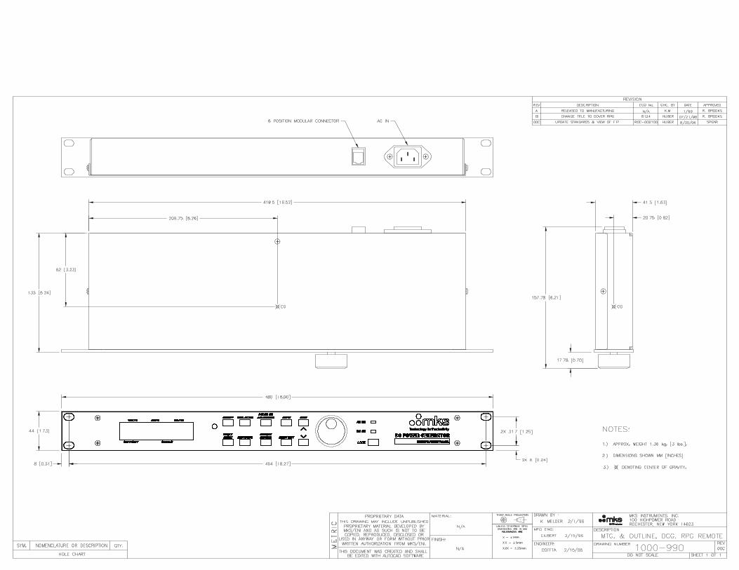


88
482.4
76.2
465
420.6
103.6 203.2
263
GROUND STUDM5X0.8 THD
3
NOTES:1.) DIMENSIONS SHOWN MILLIMETER [INCH].
2.) UNLESS OTHERWISE SPECIFIED, ALL DIMENSIONS SHALL BE 3.2mm [.125"].
3 UNIT MUST HAVE MINIMUM OF 12.7 [0.5"] CLEARANCE FOR VENTILATION.
4.) WEIGHT: 1.36 KG [3 lbs.]
REVISIONSREV. DESCRIPTION CHANGE NO. APPROVED
REV
SHEET 1 OF 1DO NOT SCALE
MKS INSTRUMENTS, INC.100 HIGHPOWER ROAD
ROCHESTER, NEW YORK 14623
DESCRIPTIONTHIRD ANGLE PROJ.
CHECKED:
DRAWN BY :
DRAWING NUMBER
THIS DOCUMENT WAS CREATED AND SHALL BE EDITED WITH SOLIDWORKS SOFTWARE.
THIS DRAWING MAY INCLUDE UNPUBLISHEDPROPRIETARY MATERIAL DEVELOPED BY
MKS/ENI AND AS SUCH IS NOT TO BE COPIED, REPRODUCED, DISCLOSED OR USED IN ANY
WAY OR FORM WITHOUT PRIOR WRITTEN AUTHORIZATION FROM MKS/ENI.
PROPRIETARY DATA
9/9/2009
ENGINEER: 9/9/2009
9/9/2009P. BATER
0011035639
MOUNTING AND OUTLINE, RPDG-SYNC-XX
MET
RIC
M. SCHWAN
M. GILBERT
UNLESS OTHERWISESPECIFIED
DIMENSIONS ARE
IN MM.