rp-7.6 using the nmra curved track center and obstacle ... · rp-7.1 states, operating rolling...
TRANSCRIPT

Page 1 of 9
Using the NMRA Curved Track Center and Obstacle Clearance
Assistant
NMRA Recommended Practices
RP-7.6
July 2017
Author(s): Van S. Fehr © 2017 NMRA
Introduction NMRA RP-7.1 Tangent Track Centers and Clearance Diagrams defines clearances that ensure proper
clearance around rolling stock (cars and locomotives) operating on tangent (straight) track only. As NMRA
RP-7.1 states, operating rolling stock on a curved track requires special track center and clearance considera-
tions.
The reason for special consideration is that on a single curved track, and on adjacent concentric curved
tracks, the track centerline spacing, track radius, and pertinent rolling stock dimensions (described later), all
reduce the actual clearance between equipment on adjacent tracks and between nearby obstacles. To ensure
that minimum acceptable clearance is not compromised requires additional track centerline spacing and ob-
stacle clearance.
NMRA TN-7 Curved Track Centerline and Obstacle Clearance Calculation Methodology, also
posted under Standards and Conformance on the NMRA Website, fully documents the engineering equa-
tions developed for that purpose. NMRA RP-7.2, RP-7.3 and RP-7.4 tabulate the results from those equa-
tions for a worst-case set of equipment in each modeling era, for interurban equipment, and for several speci-
fied track radii. Most modelers will find those tables, and their accompanying instructions, sufficient for
their layout planning and construction purposes.
However, modelers who may wish more specific results for equipment and trackwork choices of their
own, and/or the optional use of superelevation, will have to make their own calculations to ensure safe oper-
ation. Those calculations may seem daunting, but the NMRA provides a companion computer program, an
“app,” that makes them for you.
The app is the NMRA Curved Track Center and Obstacle Clearance Assistant (henceforth the Assis-
tant). It is simple to use, and operates on almost any device having internet access. In addition to curved
track centers and obstacle clearance, the Assistant also calculates the increased clearance and tunnel dia-
gram dimensions necessary for curved track, as NMRA RP-7.5 describes.
The Assistant You will find the Assistant posted on the NMRA Website. In the Standards pull-down menu, select
Standards and Recommended Practices, and scroll down to this document (NMRA RP-7.6). The Assis-
tant is posted right next to it. Click or tap Assistant, and the screen you see in Figure 1 will open for use in
your internet browser (e.g., Internet Explorer, Edge, Chrome, Mozilla, etc.).
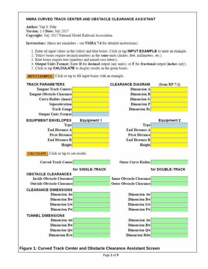
The screen consists of three sections: The first is a list of simplified instructions. The second section is a
set of yellow and blue boxes in which you enter required information. The third is a set of green boxes that
display the calculated results.
There are also two orange buttons, one labeled INPUT EXAMPLE and the other CALCULATE. When
you click (or tap) the INPUT EXAMPLE button, the Assistant will fill all the input boxes as the top part of Figure 2 illustrates. When you click (or tap) the CALCULATE button, the app makes the necessary calcu-
lations and displays the results in the green boxes as the lower part of Figure 2 illustrates.
The yellow boxes require numerical information specified in decimal format. The calculations are inde-
pendent of modeling scale, so you may use any measurement units you like, as long as they are all the same.
For example, you may use all feet, or all inches, but may not mix feet and inches. You may use all millime-
ters, or all meters, but may not mix them. The calculated results are displayed in the same measurement units
as the input information.
Page 2 of 9
Figure 1: Curved Track Center and Obstacle Clearance Assistant Screen

Page 3 of 9
The blue boxes require text information, as the input example shows in the equipment Type boxes. You
may control the format of the calculated results using the Output Units Format entry. Enter a D to display
results in decimal format with two decimal places. The entry is not case sensitive, so you may use an upper
or lower case letter. Decimal format may be used for any measurement units. When you use inches, you may
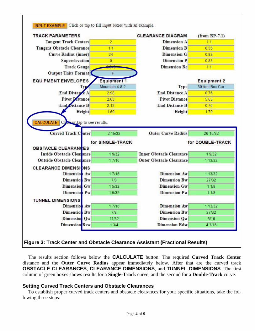
enter an F to display results in fractional format, rounded to the nearest 1/32 inch, as Figure 3 illustrates.
Fractional format applies only to inches. Using it for other measurement units has no useful meaning. The
INPUT EXAMPLE information that Figure 2 and Figure 3 shows is the same input information for the
examples that follow later.
Figure 2: Track Center and Obstacle Clearance Assistant (Example One – Branch Line)
Page 4 of 9
The results section follows below the CALCULATE button. The required Curved Track Center
distance and the Outer Curve Radius appear immediately below. After that are the curved track
OBSTACLE CLEARANCES, CLEARANCE DIMENSIONS, and TUNNEL DIMENSIONS. The first
column of green boxes shows results for a Single-Track curve, and the second for a Double-Track curve.
Setting Curved Track Centers and Obstacle Clearances To establish proper curved track centers and obstacle clearances for your specific situations, take the fol-
lowing three steps:
Figure 3: Track Center and Obstacle Clearance Assistant (Fractional Results)

Page 5 of 9
Step 1: Set your minimum Tangent Track Center, Tangent Obstacle Clearance, and other dimensions
Step 2: Determine which of your rolling stock equipment is limiting
Step 3: Use the Assistant to calculate the required track centers and obstacle clearances
The first two steps describe how to prepare input for the Assistant. These steps are straightforward, but
the second takes some explanation. The third step is easily accomplished by running the Assistant, and uses
two examples that demonstrate its use. The sections that follow describe these three steps in detail.
STEP 1: Set Minimum Tangent Track Center and Obstacle Clearance To ensure safe and unobstructed operation you must first establish your minimum Tangent Track Center
spacing and your minimum Tangent Obstacle Clearance. For good results, the NMRA recommends those
defined in NMRA RP-7.1. For scaling to modeling scales not listed, prototype dimensions appear in the first
row of the tables in RP-7.1. For minimum Tangent Obstacle Clearance, the NMRA recommends using
dimension A from RP-7.1.
You may select any minimum values you desire. Using values larger than the recommended minimums is
always acceptable, e.g., allowing extra space for fingers when handling equipment. Be aware that if your
minimums become too large, they may begin to limit the space available for other modeling uses. Using
smaller minimum values is neither recommended nor prohibited, but, use caution when doing so.
Set your desired Curve Radius. This is the radius of a single curve, or the inner radius of two concentric
curves. Set the amount of Superelevation, making sure to use the same units as all other input. Enter the
Track Gauge as well. You should use the minimum Track Gauge specified in NMRA Standard S-1.1, S-
1.2 or S-1.3, for your modeling scale. Also decide which Output Unit Format you like, decimal (D) or
fractional (F).
For later calculation of the modified clearance and tunnel dimensions, select the tangent track clearance
diagram dimensions A, B, G, P, and Rc defined in NMRA RP-7.1 for your modeling scale and era. To be
consistent, you should use the same value for dimension A that you entered for the Tangent Obstacle
Clearance. All of the modified clearance and tunnel dimensions depend on this value.
Figure 4: Typical Freight, Passenger and Diesel Equipment Envelope (no scale)
Bolster Pivots
PD BDAD
Railhead
Bolster Pivots
Longitudinal centerline
Vertical centerline
Bolster Pivots
End Distance A End Distance BPivot Distance
Height

Page 6 of 9
STEP 2: Determine Limiting Equipment As mentioned above, curved track centers and obstacle clearance depends in part on rolling stock equip-
ment dimensions. Of all the equipment in the roster you operate (or want to), there are only two specific
equipment types that affect track center and obstacle clearance. In this step, you determine which ones they
are.
Equipment Envelope All types of rolling stock fit inside a rectangular box-shaped equipment envelope that Figure 4 illus-
trates. For equipment on hand, you can easily measure the dimensions shown using a standard ruler or scale.
You will need some kind of dimensioned reference drawing to determine dimensions for equipment that is
not on hand. As shown, Figure 4 applies to any typical freight car, passenger car, or diesel locomotive. A
curved track centerline passes directly under the bolster pivots. Thus, the line between the bolsters is a chord
of the curve, and orients the body on it.
Perhaps not obvious is that a steam engine also uses the same box-shaped equipment envelope. The upper
diagram in Figure 5 shows a typical steam locomotive whose “pivot” distance is the distance between the
axles of the outermost driving wheels. These “pivots” orient the locomotive body on the curve because the
curve centerline passes under the midpoints of the outermost driver axles.
Figure 5: Typical Steam Locomotive Equipment Envelopes (no scale)
BD
“Pivot” “Pivot”
Typical Steam Loco
“Pivot”
Rear engine driver frame rigidly attached to locomotive body.Orients body on curve.
Front engine driver frame swings (articulates) laterally around vertical hinge.No effect on locomotive body orientation on curve
Rear engine
Front engine
“Pivot”
AD BDPD
AD PD
Driver frame rigidly attached to locomotive body. Orients body on curve.
Typical Articulated Steam Loco
Vertical hinge

Page 7 of 9
A typical articulated steam locomotive, shown in the lower diagram of Figure 5, is a special case. Many
brass articulated locomotive models are faithful to the prototype. The rear engine frame is rigidly attached to
the boiler, and the front engine frame swings laterally (articulates) around a vertical “hinge” on the front of
the rear engine frame. Because the front engine swings somewhat like a leading truck, only the rear engine
orients the locomotive on a curve. In this case, the “pivot” distance is the distance between the axles of the
outermost drivers on the rear engine. An exception is the SP Cab Forward, on which the front engine is rig-
idly mounted, and the rear engine articulates.
Not all articulated steam locomotive models, especially the newer plastic or hybrid varieties, are faithful
to the prototype “hinge” arrangement. To allow operation on tighter curves, model manufacturers sometimes
mount each engine on its own bolster. This makes each engine operate like a truck on a diesel locomotive, or
on a freight or passenger car. In this case, the pivot distance is the distance between the bolsters.
You should use some judgment when establishing the equipment envelope end distances A and B. Cab-
unit diesels, some streamlined steam locos, and some passenger observation cars have rounded front ends
and/or “boat tail” rear ends that curve away from sides that are nominally parallel to the rails. In this case,
use the distance to end of the parallel side as the end distance. Ordinary steam locos, hood-unit diesels, box
cabs, and ordinary passenger cars have easily identified corners.
Make a similar judgement for equipment height where equipment roofs slant or curve away from the oth-
erwise vertical sides. For steam engines, the circular cross-section boiler makes height selection a little trick-
ier. The height, important when using superelevated curves, may be at a side walkway or the roof line above
a cab side-window.
Limiting Equipment On curved track, the equipment side on the inside of the curve extends inward from the track centerline
more than it does on tangent track. Similarly, the equipment end corners extend further outward from the
centerline. In combination, these two factors are the reasons why track centers and obstacle clearance must
be increased on curved track.
It turns out that your equipment type having the longest pivot distance, and another type having the long-
est end distance, establish the limiting case that determines the required curved track centers and obstacle
clearance for your railroad. Of all the equipment in your roster, visual inspection likely determines which
two types are limiting. If not, taking a few measurements will quickly identify them. By measurement, or
from a drawing, determine the equipment envelope dimensions in Figure 4 or Figure 5 for each. It is pos-
sible, although unlikely, that one equipment type will have both the longest pivot distance and the longest
end distance.
Once you have the envelope dimensions for your limiting equipment, you are ready for Step 3.
STEP 3. Calculate Track Center and Obstacle Clearance Before going further, note that superelevation affects curved track center and obstacle clearance. Superel-
evation is the amount the outer rail extends above the inner rail, banking the curve. Superelevation is not re-
quired in model railroading, but many modelers use it for its visual effect. If you use it, the Assistant takes
the effect of superelevation into account.
Establishing curved track centers, obstacle clearances, and increased clearance diagram dimensions is
best described by two simple examples. By working through these two examples in detail you will quickly
see how easy the Assistant is to use. They are not extreme cases, but they illustrate the need for increased
curved track center and obstacle clearance well.
In these examples, you model the Classic era in HO scale. In Step 1, you decide to use a minimum Tan-
gent Track Center of 2.0 inches, slightly wider than the recommended value of 1.79 inches (13 prototype
feet) in NMRA RP-7.1 (a lot of HO modelers use this simpler value). You accept the recommendation for
minimum Tangent Obstacle Clearance of 1.1 inches (Classic era, HO Scale, dimension A in NMRA RP-
7.1). From NMRA S-1.2, the Track Gauge is 0.649 inches (the minimum value). The other CLEARANCE DIAGRAMS dimensions, B, G, P, and Rc, also come directly from NMRA RP-7.1.

Page 8 of 9
In Step 2, you make a visual inspection of your roster. It quickly reveals that your 50-foot box cars have
the longest pivot distance, and your Mountain 4-8-2 steam locomotive has the longest end distance. You
make careful measurements of the dimensions shown in Figure 4 and Figure 5, and get these HO scale
values in inches:
Dimensions Mountain 4-8-2 50-foot Box Car
End Distance A 2.98 0.76
Pivot Distance 2.63 5.63
End Distance B 2.12 0.76
Height 1.69 1.79
Figure 6: Track Center and Obstacle Clearance Assistant (Example Two – Main Line Case)
Page 9 of 9
These are the same dimensions you see in Figure 2, so you don’t need to reenter them if you’ve clicked
the INPUT EXAMPLE button. It does not matter which equipment type you select as Equipment 1 or
Equipment 2. It also does not matter if End Distance A or End Distance B is the larger. The program will
determine which end has the longer end distance on each. Where only one type of equipment is limiting (un-
usual, but possible), you would enter the same dimensions for both Equipment 1 and Equipment 2.
In Step 3, you want to look at two scenarios. The first is a single-track curve having a radius of 24 inches,
located on a branch line. Trains run slowly on this branch so you decide to use no superelevation.
The second scenario is a fast, double-track mainline, whose inner track radius is also 24 inches. Because
it looks impressive, you decide to use about 3½ prototype inches of superelevation, or about 0.04 inches in
HO scale, on both tracks.
The curves in each scenario also pass through tunnels.
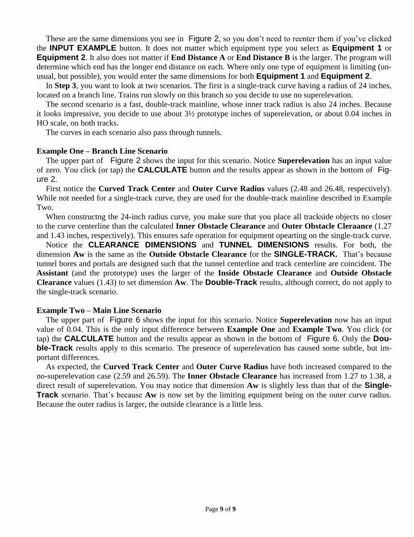
Example One – Branch Line Scenario
The upper part of Figure 2 shows the input for this scenario. Notice Superelevation has an input value
of zero. You click (or tap) the CALCULATE button and the results appear as shown in the bottom of Fig-ure 2.
First notice the Curved Track Center and Outer Curve Radius values (2.48 and 26.48, respectively).
While not needed for a single-track curve, they are used for the double-track mainline described in Example
Two.
When constructng the 24-inch radius curve, you make sure that you place all trackside objects no closer
to the curve centerline than the calculated Inner Obstacle Clearance and Outer Obstacle Cleraance (1.27
and 1.43 inches, respectively). This ensures safe operation for equipment opearting on the single-track curve.
Notice the CLEARANCE DIMENSIONS and TUNNEL DIMENSIONS results. For both, the
dimension Aw is the same as the Outside Obstacle Clearance for the SINGLE-TRACK. That’s because
tunnel bores and portals are designed such that the tunnel centerline and track centerline are coincident. The
Assistant (and the prototype) uses the larger of the Inside Obstacle Clearance and Outside Obstacle
Clearance values (1.43) to set dimension Aw. The Double-Track results, although correct, do not apply to
the single-track scenario.
Example Two – Main Line Scenario
The upper part of Figure 6 shows the input for this scenario. Notice Superelevation now has an input
value of 0.04. This is the only input difference between Example One and Example Two. You click (or
tap) the CALCULATE button and the results appear as shown in the bottom of Figure 6. Only the Dou-ble-Track results apply to this scenario. The presence of superelevation has caused some subtle, but im-
portant differences.
As expected, the Curved Track Center and Outer Curve Radius have both increased compared to the
no-superelevation case (2.59 and 26.59). The Inner Obstacle Clearance has increased from 1.27 to 1.38, a
direct result of superelevation. You may notice that dimension Aw is slightly less than that of the Single-Track scenario. That’s because Aw is now set by the limiting equipment being on the outer curve radius.
Because the outer radius is larger, the outside clearance is a little less.