routing and switching exam - · pdf filecritical concepts . expert reference series of white...
TRANSCRIPT

Expert Reference Series of White Papers
Critical Concepts of the 200-120 CCNA
Routing and Switching Exam
1-800-COURSES www.globalknowledge.com

Critical Concepts of the 200-120 CCNA Routing and Switching Exam Diane Teare, Global Knowledge Instructor, Course Director, P.Eng, PMP, B.A.Sc., M.A.Sc., CCNP, CCDP, CCSI
Table of Contents Introduction ................................................................................................................................................................... 6
OSI Model Layers ........................................................................................................................................................... 6
OSI Model vs. TCP/IP Protocol Suite ............................................................................................................................. 7
TCP/IP Transport Layer Protocols .................................................................................................................................. 7
TCP Header ................................................................................................................................................................ 8
UDP Header ............................................................................................................................................................... 8
TCP and UDP Port Numbers ...................................................................................................................................... 8
Internet Layer Protocols ................................................................................................................................................ 8
IPv4 ................................................................................................................................................................................ 9
IPv4 Packet Header ................................................................................................................................................... 9
IPv4 Address Format ................................................................................................................................................. 9
Converting Binary to Decimal ............................................................................................................................... 9
Converting Decimal to Binary ............................................................................................................................. 10
IPv4 Address Classes ................................................................................................................................................ 10
Reserved IPv4 Addresses ......................................................................................................................................... 10
Private IPv4 Addresses ............................................................................................................................................ 11
Subnet Masks .......................................................................................................................................................... 11
Default Subnet Masks ......................................................................................................................................... 11
Example Subnet Masks for Class C Addresses .................................................................................................... 11
Example Subnet Masks for Class B Addresses .................................................................................................... 11
Example Subnet Masks for Class A Addresses ................................................................................................... 12
Steps for Planning IPv4 Addresses .......................................................................................................................... 12
Steps for Determining the Subnet Address from a Given IPv4 Address and Mask ............................................... 12
IPv4 VLSM Example ................................................................................................................................................. 12
IPv6 .............................................................................................................................................................................. 13
IPv6 Advanced Features .......................................................................................................................................... 13
Copyright ©2014 Global Knowledge Training LLC. All rights reserved. 2
Hexadecimal and Converting Between Binary and Hexadecimal .......................................................................... 14
IPv6 Addresses......................................................................................................................................................... 15
IPv4 vs. IPv6 Address ........................................................................................................................................... 15
IPv6 Address Representation .............................................................................................................................. 15
IPv6 EUI-64 Interface ID ...................................................................................................................................... 15
IPv4 vs. IPv6 Header ................................................................................................................................................ 15
IPv6 Header Detail .................................................................................................................................................. 16
IPv6 Address Types .................................................................................................................................................. 17
IPv6 Address Assignment ........................................................................................................................................ 17
Ethernet ....................................................................................................................................................................... 18
MAC Addresses ....................................................................................................................................................... 18
Ethernet Frame Types ............................................................................................................................................. 18
Ethernet II ........................................................................................................................................................... 18
IEEE 802.3 ........................................................................................................................................................... 18
IEEE 802.2 LLC ..................................................................................................................................................... 18
IEEE 802.2 LLC SNAP ........................................................................................................................................... 18
IEEE 802.1q ......................................................................................................................................................... 18
Ethernet Cables ....................................................................................................................................................... 19
WANs ........................................................................................................................................................................... 20
WAN Connection Types .......................................................................................................................................... 20
WAN Terminology................................................................................................................................................... 20
WAN Devices ........................................................................................................................................................... 21
Serial WAN Cables ................................................................................................................................................... 21
WAN Serial Encapsulation Types ............................................................................................................................ 21
Frame Relay Terminology ....................................................................................................................................... 22
How Protocol Layers Interact ...................................................................................................................................... 22
LAN Switches ............................................................................................................................................................... 22
LAN Switch Functions.............................................................................................................................................. 22
Collision Domains and Broadcast Domains ............................................................................................................ 22
Switching/Bridging Issues ....................................................................................................................................... 23
802.1d Spanning Tree Protocol .............................................................................................................................. 23
802.1w Rapid Spanning Tree Protocol ................................................................................................................... 24
Comparison of Bridges and Switches ..................................................................................................................... 24
Half-Duplex vs. Full-Duplex...................................................................................................................................... 25
Copyright ©2014 Global Knowledge Training LLC. All rights reserved. 3
STP on Trunks .......................................................................................................................................................... 25
STP Port Costs.......................................................................................................................................................... 25
EtherChannel ........................................................................................................................................................... 25
Routers......................................................................................................................................................................... 26
Types of Routes ....................................................................................................................................................... 26
Routing Protocols .................................................................................................................................................... 26
Interior vs. Exterior ............................................................................................................................................. 26
Distance Vector vs. Link State vs. Advanced Distance Vector ........................................................................... 27
Classless vs. Classful ............................................................................................................................................. 27
Examples of IPv4 Routing Protocols ................................................................................................................... 28
Examples of IPv6 Routing Protocols ................................................................................................................... 29
Administrative Distance ...................................................................................................................................... 29
Metric .................................................................................................................................................................. 30
OSPF Concepts .................................................................................................................................................... 30
EIGRP Concepts ................................................................................................................................................... 30
Router Storage Locations ....................................................................................................................................... 31
IPv4 Access Lists (ACLs) ........................................................................................................................................... 31
Router Boot Sequence ............................................................................................................................................ 32
Configuration Register ............................................................................................................................................ 32
Network Address Translation ................................................................................................................................. 33
NAT Addresses .................................................................................................................................................... 33
Types of NAT ...................................................................................................................................................... 33
First Hop Redundancy Protocols ............................................................................................................................. 33
Network Management ................................................................................................................................................ 33
Syslog Severity Levels .............................................................................................................................................. 33
NetFlow Flow .......................................................................................................................................................... 33
Virtual Private Networks (VPNs) ................................................................................................................................. 34
Types of VPNs.......................................................................................................................................................... 34
IP Security (IPSec) .................................................................................................................................................... 34
Generic Routing Encapsulation (GRE) Tunnels ....................................................................................................... 34
Cisco IOS Command Line Interface (CLI) and Commands .......................................................................................... 34
Cisco IOS EXEC Operating Modes ........................................................................................................................... 34
General Commands ................................................................................................................................................. 35
General Configuration Commands ......................................................................................................................... 37
Copyright ©2014 Global Knowledge Training LLC. All rights reserved. 4

Interface Configuration Commands ....................................................................................................................... 39
General Switch Commands ..................................................................................................................................... 40
General Switch Configuration Commands ............................................................................................................. 40
Switch Interface Configuration Commands ............................................................................................................ 41
General IP Commands ............................................................................................................................................. 41
IP Configuration Commands ................................................................................................................................... 42
Wildcard Masks ....................................................................................................................................................... 43
General IPv6 Commands ......................................................................................................................................... 44
IPv6 Configuration Commands ............................................................................................................................... 44
IP ACL Configuration Commands ........................................................................................................................... 45
General Network Address Translation Commands ................................................................................................ 46
Network Address Translation Configuration Commands ...................................................................................... 46
General DHCP Commands ...................................................................................................................................... 47
DHCP Configuration Commands............................................................................................................................. 47
General WAN Commands ....................................................................................................................................... 47
WAN Configuration Commands ............................................................................................................................. 47
Cisco ROMMON Commands ........................................................................................................................................ 48
Windows Commands ................................................................................................................................................... 48
Cisco IOS Filenames and Packaging ............................................................................................................................ 48
Cisco IOS Filename Structure .................................................................................................................................. 48
Feature Set Packaging starting in Cisco IOS 15.0 ................................................................................................... 48
Feature Set Packaging prior to Cisco IOS 15.0 ....................................................................................................... 49
Copyright ©2014 Global Knowledge Training LLC. All rights reserved. 5
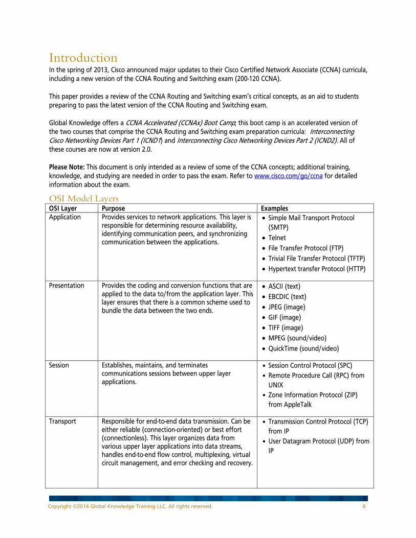
Introduction In the spring of 2013, Cisco announced major updates to their Cisco Certified Network Associate (CCNA) curricula, including a new version of the CCNA Routing and Switching exam (200-120 CCNA). This paper provides a review of the CCNA Routing and Switching exam’s critical concepts, as an aid to students preparing to pass the latest version of the CCNA Routing and Switching exam. Global Knowledge offers a CCNA Accelerated (CCNAx) Boot Camp; this boot camp is an accelerated version of the two courses that comprise the CCNA Routing and Switching exam preparation curricula: Interconnecting Cisco Networking Devices Part 1 (ICND1) and Interconnecting Cisco Networking Devices Part 2 (ICND2). All of these courses are now at version 2.0. Please Note: This document is only intended as a review of some of the CCNA concepts; additional training, knowledge, and studying are needed in order to pass the exam. Refer to www.cisco.com/go/ccna for detailed information about the exam.
OSI Model Layers OSI Layer Purpose Examples Application Provides services to network applications. This layer is
responsible for determining resource availability, identifying communication peers, and synchronizing communication between the applications.
• Simple Mail Transport Protocol (SMTP)
• Telnet • File Transfer Protocol (FTP) • Trivial File Transfer Protocol (TFTP) • Hypertext transfer Protocol (HTTP)
Presentation Provides the coding and conversion functions that are applied to the data to/from the application layer. This layer ensures that there is a common scheme used to bundle the data between the two ends.
• ASCII (text) • EBCDIC (text) • JPEG (image) • GIF (image) • TIFF (image) • MPEG (sound/video) • QuickTime (sound/video)
Session Establishes, maintains, and terminates communications sessions between upper layer applications.
• Session Control Protocol (SPC) • Remote Procedure Call (RPC) from
UNIX • Zone Information Protocol (ZIP)
from AppleTalk
Transport Responsible for end-to-end data transmission. Can be either reliable (connection-oriented) or best effort (connectionless). This layer organizes data from various upper layer applications into data streams, handles end-to-end flow control, multiplexing, virtual circuit management, and error checking and recovery.
• Transmission Control Protocol (TCP) from IP
• User Datagram Protocol (UDP) from IP
Copyright ©2014 Global Knowledge Training LLC. All rights reserved. 6

OSI Layer Purpose Examples Network This layer allows data flows to access the network.
The network layer addresses define a network hierarchy. Network devices are normally grouped together based on their common network layer address.
• Internet Protocol (IP) version 4 (IPv4)
• IP version 6 (IPv6)
Data Link Provides either reliable or best effort transmission of data across a physical medium. Most networks use a best effort data link layer, such as Ethernet. The data Link Layer for local area networks (LANs) provides a physical address to each device called a Media Access Control (MAC) address. MAC addresses are typically burned into the network interface card (NIC). The LAN data link layer also uses a Logical Link Control (LLC) to indicate the type of network layer data that is encapsulated inside the frame.
LAN: • Ethernet/IEEE 802.3 (include Fast
Ethernet, Gigabit Ethernet, etc.) • Token Ring /IEEE 802.5 • FDDI (from ANSI)
Wide area network (WAN): • High-Level Data-link Control (HDLC) • Point-to-Point Protocol (PPP) • Frame Relay
Physical Defines the electrical, mechanical, and functional specifications for maintaining a physical link between network devices. This layer is responsible for such characteristics as voltage levels, timing and clock rates, maximum transmission distances, and the physical connectors used.
LAN: • Category 5 cabling
WAN: • EIA/TIA-232 • EIA/TIA-449 • V.35
OSI Model vs. TCP/IP Protocol Suite OSI Model Layer Number
OSI Model Layer
TCP/IP Protocol Suite Layer
Protocol Data Unit Network Device
7 Application Application
Data
6 Presentation 5 Session 4 Transport Transport Segment 3 Network Internet Packet (or Datagram) Multilayer Switch or Router 2 Data Link Link*
(or Network Access) Frame Layer 2 Switch or Bridge
1 Physical Bits Hub *The Link or Network Access layer is sometimes shown as the separate Data Link and Physical layers.
TCP/IP Transport Layer Protocols TCP is a reliable, connection-oriented, protocol that uses sequence and acknowledgement numbers to provide reliability. TCP verifies that the remote end is listening prior to sending data, using a three-way handshake: SYN, SYN/ACK, ACK. UDP is a best-effort, connectionless, protocol that does not have sequence or acknowledgement numbers, and does not do end-to-end verification.
Copyright ©2014 Global Knowledge Training LLC. All rights reserved. 7
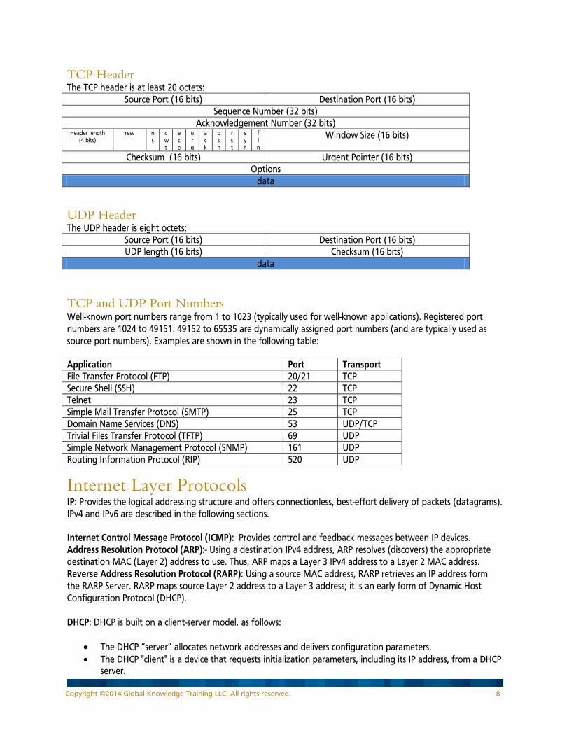
TCP Header The TCP header is at least 20 octets:
Source Port (16 bits) Destination Port (16 bits) Sequence Number (32 bits)
Acknowledgement Number (32 bits) Header length
(4 bits) resv n
s cwt
ece
urg
ack
psh
rst
syn
fln
Window Size (16 bits)
Checksum (16 bits) Urgent Pointer (16 bits) Options
data
UDP Header The UDP header is eight octets:
Source Port (16 bits) Destination Port (16 bits) UDP length (16 bits) Checksum (16 bits)
data
TCP and UDP Port Numbers Well-known port numbers range from 1 to 1023 (typically used for well-known applications). Registered port numbers are 1024 to 49151. 49152 to 65535 are dynamically assigned port numbers (and are typically used as source port numbers). Examples are shown in the following table: Application Port Transport File Transfer Protocol (FTP) 20/21 TCP Secure Shell (SSH) 22 TCP Telnet 23 TCP Simple Mail Transfer Protocol (SMTP) 25 TCP Domain Name Services (DNS) 53 UDP/TCP Trivial Files Transfer Protocol (TFTP) 69 UDP Simple Network Management Protocol (SNMP) 161 UDP Routing Information Protocol (RIP) 520 UDP
Internet Layer Protocols IP: Provides the logical addressing structure and offers connectionless, best-effort delivery of packets (datagrams). IPv4 and IPv6 are described in the following sections. Internet Control Message Protocol (ICMP): Provides control and feedback messages between IP devices. Address Resolution Protocol (ARP):- Using a destination IPv4 address, ARP resolves (discovers) the appropriate destination MAC (Layer 2) address to use. Thus, ARP maps a Layer 3 IPv4 address to a Layer 2 MAC address. Reverse Address Resolution Protocol (RARP): Using a source MAC address, RARP retrieves an IP address form the RARP Server. RARP maps source Layer 2 address to a Layer 3 address; it is an early form of Dynamic Host Configuration Protocol (DHCP). DHCP: DHCP is built on a client-server model, as follows:
• The DHCP “server” allocates network addresses and delivers configuration parameters. • The DHCP "client" is a device that requests initialization parameters, including its IP address, from a DHCP
server.
Copyright ©2014 Global Knowledge Training LLC. All rights reserved. 8
DHCP supports three mechanisms for IP address allocation:
1. Automatic: DHCP assigns a permanent IP address to a client. 2. Dynamic: DHCP assigns an IP address from a pool of addresses to a client for a limited period of time
(called a lease). Dynamic allocation is the only mechanism that allows automatic reuse of an address that is no longer needed by the client to which it was assigned.
3. Manual: A specific client IP address is assigned by the network administrator, and DHCP is used simply to convey the assigned address to the client.
DHCP has four phases:
1. DHCP discover: Broadcast from client 2. DHCP offer: Unicast from server 3. DHCP request: Broadcast from client 4. DHCP acknowledgement: Unicast from server
Domain Name System (DNS): Resolves domain names to IP addresses.
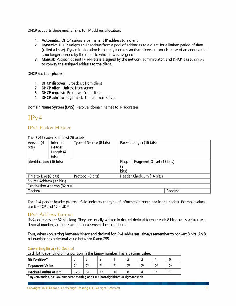
IPv4 IPv4 Packet Header The IPv4 header is at least 20 octets: Version (4 bits)
Internet Header Length (4 bits)
Type of Service (8 bits) Packet Length (16 bits)
Identification (16 bits) Flags (3 bits)
Fragment Offset (13 bits)
Time to Live (8 bits) Protocol (8 bits) Header Checksum (16 bits) Source Address (32 bits) Destination Address (32 bits) Options Padding
The IPv4 packet header protocol field indicates the type of information contained in the packet. Example values are 6 = TCP and 17 = UDP.
IPv4 Address Format IPv4 addresses are 32 bits long. They are usually written in dotted decimal format: each 8-bit octet is written as a decimal number, and dots are put in between these numbers. Thus, when converting between binary and decimal for IPv4 addresses, always remember to convert 8 bits. An 8 bit number has a decimal value between 0 and 255. Converting Binary to Decimal Each bit, depending on its position in the binary number, has a decimal value:
Bit Position♦ 7 6 5 4 3 2 1 0
Exponent Value 27 26 25 24 23 22 21 20
Decimal Value of Bit 128 64 32 16 8 4 2 1 ♦ By convention, bits are numbered starting at bit 0 = least-significant or right-most bit
Copyright ©2014 Global Knowledge Training LLC. All rights reserved. 9
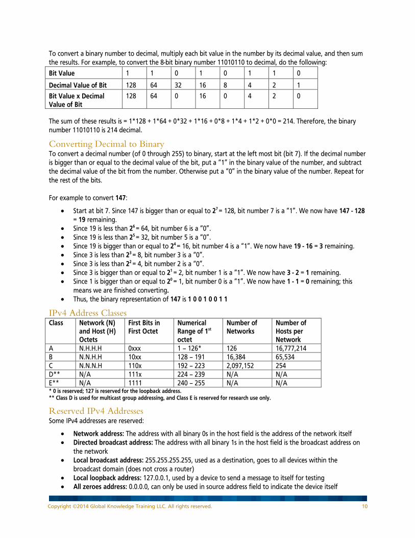
To convert a binary number to decimal, multiply each bit value in the number by its decimal value, and then sum the results. For example, to convert the 8-bit binary number 11010110 to decimal, do the following:
Bit Value 1 1 0 1 0 1 1 0
Decimal Value of Bit 128 64 32 16 8 4 2 1
Bit Value x Decimal Value of Bit
128 64 0 16 0 4 2 0
The sum of these results is = 1*128 + 1*64 + 0*32 + 1*16 + 0*8 + 1*4 + 1*2 + 0*0 = 214. Therefore, the binary number 11010110 is 214 decimal.
Converting Decimal to Binary To convert a decimal number (of 0 through 255) to binary, start at the left most bit (bit 7). If the decimal number is bigger than or equal to the decimal value of the bit, put a “1” in the binary value of the number, and subtract the decimal value of the bit from the number. Otherwise put a “0” in the binary value of the number. Repeat for the rest of the bits. For example to convert 147:
• Start at bit 7. Since 147 is bigger than or equal to 27 = 128, bit number 7 is a “1”. We now have 147 - 128 = 19 remaining.
• Since 19 is less than 26 = 64, bit number 6 is a “0”. • Since 19 is less than 25 = 32, bit number 5 is a “0”. • Since 19 is bigger than or equal to 24 = 16, bit number 4 is a “1”. We now have 19 - 16 = 3 remaining. • Since 3 is less than 23 = 8, bit number 3 is a “0”. • Since 3 is less than 22 = 4, bit number 2 is a “0”. • Since 3 is bigger than or equal to 21 = 2, bit number 1 is a “1”. We now have 3 - 2 = 1 remaining. • Since 1 is bigger than or equal to 20 = 1, bit number 0 is a “1”. We now have 1 - 1 = 0 remaining; this
means we are finished converting. • Thus, the binary representation of 147 is 1 0 0 1 0 0 1 1
IPv4 Address Classes Class Network (N)
and Host (H) Octets
First Bits in First Octet
Numerical Range of 1st octet
Number of Networks
Number of Hosts per Network
A N.H.H.H 0xxx 1 – 126* 126 16,777,214 B N.N.H.H 10xx 128 – 191 16,384 65,534 C N.N.N.H 110x 192 – 223 2,097,152 254 D** N/A 111x 224 – 239 N/A N/A E** N/A 1111 240 – 255 N/A N/A * 0 is reserved; 127 is reserved for the loopback address. ** Class D is used for multicast group addressing, and Class E is reserved for research use only.
Reserved IPv4 Addresses Some IPv4 addresses are reserved:
• Network address: The address with all binary 0s in the host field is the address of the network itself • Directed broadcast address: The address with all binary 1s in the host field is the broadcast address on
the network • Local broadcast address: 255.255.255.255, used as a destination, goes to all devices within the
broadcast domain (does not cross a router) • Local loopback address: 127.0.0.1, used by a device to send a message to itself for testing • All zeroes address: 0.0.0.0, can only be used in source address field to indicate the device itself
Copyright ©2014 Global Knowledge Training LLC. All rights reserved. 10
Private IPv4 Addresses The private IPv4 addresses are as follows:
• 10.0.0.0 through 10.255.255.255 • 172.16.0.0 through 172.31.255.255 • 192.168.0.0 through 192.168.255.255
Subnet Masks Subnet bits are “borrowed” from host bits. The subnet mask indicates how to interpret the IP address; every address has a subnet mask as an “interpreter”:
• A binary “1” in the subnet mask indicates that the corresponding bit in the IP address is a subnet or network bit. The number of network bits is determined by the address class.
• A binary “0” in the subnet mask indicates that the corresponding bit in the IP address is a host bit. With “s“ subnet bits, the number of subnets is 2s. With “h“ host bits, the number of hosts per subnet is: 2h– 2.
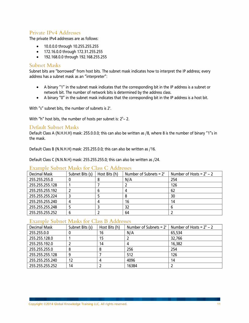
Default Subnet Masks Default Class A (N.H.H.H) mask: 255.0.0.0; this can also be written as /8, where 8 is the number of binary “1”s in the mask. Default Class B (N.N.H.H) mask: 255.255.0.0; this can also be written as /16. Default Class C (N.N.N.H) mask: 255.255.255.0; this can also be written as /24.
Example Subnet Masks for Class C Addresses Decimal Mask Subnet Bits (s) Host Bits (h) Number of Subnets = 2s Number of Hosts = 2h – 2 255.255.255.0 0 8 N/A 254 255.255.255.128 1 7 2 126 255.255.255.192 2 6 4 62 255.255.255.224 3 5 8 30 255.255.255.240 4 4 16 14 255.255.255.248 5 3 32 6 255.255.255.252 6 2 64 2
Example Subnet Masks for Class B Addresses Decimal Mask Subnet Bits (s) Host Bits (h) Number of Subnets = 2s Number of Hosts = 2h – 2 255.255.0.0 0 16 N/A 65,534 255.255.128.0 1 15 2 32,766 255.255.192.0 2 14 4 16,382 255.255.255.0 8 8 256 254 255.255.255.128 9 7 512 126 255.255.255.240 12 4 4096 14 255.255.255.252 14 2 16384 2
Copyright ©2014 Global Knowledge Training LLC. All rights reserved. 11

Example Subnet Masks for Class A Addresses Decimal Mask Subnet Bits (s) Host Bits (h) Number of Subnets = 2s Number of Hosts = 2h – 2 255.0.0.0 0 24 N/A 16,777,214 255.128.0.0 1 23 2 8,388,606 255.192.0.0 2 22 4 4,194,302 255.255.255.0 16 8 65,536 254 255.255.255.192 18 6 262,144 62 255.255.255.240 20 4 1,048,576 14 255.255.255.252 22 2 4,194,304 2
Steps for Planning IPv4 Addresses 1. Determine the address space to use (either a public or private network number). 2. Determine the number of subnets and number of host (device) addresses per subnet required. 3. From #2, determine the number of subnet bits to use (s, where 2s = # subnets). 4. From #3, determine the subnet mask to use. 5. Apply the subnet mask (from #4) to the IP address space (from #1) to determine the subnet and host
(device) addresses. 6. Assign the host (device) addresses to specific device interfaces.
Steps for Determining the Subnet Address from a Given IPv4 Address and Mask Given a device IPv4 address and its subnet mask:
1. Write the address in binary. 2. Write the mask in binary, below the address. 3. Draw a vertical line between the binary 1s and the 0s in the mask; extend this line up into the address
bits. This line divides the network/subnet bits from the host bits in the address. 4. Make four copies of the address bits that are above the 1s in the mask; these are network/subnet bits. 5. In the first of these copies, fill in all the bits to the right of these bits with 0s. This sets all of the host bits
to binary “0” and is the address of the subnet. 6. In the last of these copies, fill in all the bits to the right of these bits with 1s. This sets all of the host bits
to binary “1” and is the address of the directed broadcast on the subnet. 7. In the second of these copies, fill in all the bits to the right of these bits with 0s, except put a 1 in the last
bit. This is the address of the first host on the subnet. In the third of these copies, fill in all the bits to the right of these bits with 1s, except put a 0 in the last bit. This is the address of the last host on the subnet.
8. To determine the address of the next subnet, increment the subnet bits by 1.
IPv4 VLSM Example Variable length subnet mask (VLSM) means to use a different (variable length) subnet mask on different subnets of the same major network (a given class A, B, or C network). VLSM allows the address space to be used more efficiently. For example, you are given the address space 172.17.0.0/16 and you need to address some LANs that may have up to 300 device addresses, and some point-to-point WANs (which have only two device addresses). For the LANs you need nine host bits (29 – 2 = 510 host addresses) and for the WANs you need two host bits (22 – 2 = 2 host addresses).
Copyright ©2014 Global Knowledge Training LLC. All rights reserved. 12

Therefore, for the LANs you can use 16 – 9 = 7 subnet bits, which would allow 27 = 128 subnets. The addresses of these subnets are as follows (with the subnet bits highlighted): 172.17.00000000.00000000 = 172.17.0.0/23 172.17.00000010.00000000 = 172.17.2.0/23 172.17.00000100.00000000 = 172.17.4.0/23 And so on, up to the last subnet: 172.17.11111110.00000000 = 172.17.254.0/23 The first of these can be used for addressing the LANs. Any unused subnet can be further subnetted for the WANs. For example, if the last subnet is not used for a LAN, it can be further subnetted for the WANs. Since only two host bits are required for the WANs, 9 – 2 = 7 subnet bits can be used, which would allow 27 = 128 WAN subnets. The addresses of these subnets are as follows (with the WAN subnet bits highlighted darker): 172.17.11111110.00000000 = 172.17.254.0/30 172.17.11111110.00000100 = 172.17.254.4/30 172.17.11111110.00001000 = 172.17.254.8/30 And so on, up to the last subnet: 172.17.11111111.11111100 = 172.17.255.252/30
IPv6 IPv6 Advanced Features Larger address space Global reachability and flexibility
Aggregation Multihoming Autoconfiguration Plug-and-play End-to-end without network address translation (NAT) Simplified renumbering
Mobility and security Built in to IPv6 Simpler header Routing efficiency
Scalable performance and forwarding rate No checksums Extension headers Flow labels
Transition richness Dual stack Tunneling (including 6to4 and manual tunnels) Translation
Copyright ©2014 Global Knowledge Training LLC. All rights reserved. 13

Hexadecimal and Converting Between Binary and Hexadecimal IPv6 addresses are written in hexadecimal. The hexadecimal system, commonly called “hex”, uses 16 symbols (as compared to the two symbols used in binary or the 10 symbols used in decimal). Since there are only 10 Arabic numbers (zero through nine), we have to use six new symbols. For these, we borrow from the alphabet, where:
• Decimal 10 becomes Hexadecimal A • Decimal 11 becomes Hexadecimal B • Decimal 12 becomes Hexadecimal C • Decimal 13 becomes Hexadecimal D • Decimal 14 becomes Hexadecimal E, and • Decimal 15 becomes Hexadecimal F
(The letters A through F can be upper or lower case, or a mixture.) Each hexadecimal digit can be represented by exactly 4 bits: Decimal Hexadecimal Binary 0 0 0000 1 1 0001 2 2 0010 3 3 0011 4 4 0100 5 5 0101 6 6 0110 7 7 0111 8 8 1000 9 9 1001 10 A 1010 11 B 1011 12 C 1100 13 D 1101 14 E 1110 15 F 1111 To convert a hexadecimal number to binary, convert each hexadecimal symbol to its binary equivalent. For example, the hexadecimal number: af34 = 1 0 1 0 1 1 1 1 0 0 1 1 0 1 0 0 \ / \ / \ / \ / a f 3 4 In Cisco devices, hexadecimal numbers are sometimes indicated by “0x” preceding the number. The above example number would therefore appear as 0xaf34. (IPv6 addresses do not use this notation.)
Copyright ©2014 Global Knowledge Training LLC. All rights reserved. 14
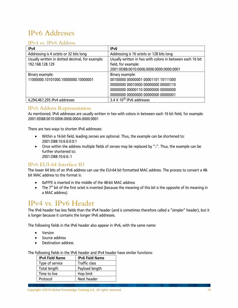
IPv6 Addresses IPv4 vs. IPv6 Address IPv4 IPv6 Addressing is 4 octets or 32 bits long Addressing is 16 octets or 128 bits long Usually written in dotted decimal, for example: 192.168.128.129
Usually written in hex with colons in between each 16 bit field, for example: 2001:0DB8:0010:0006:0006:0000:0000:0001
Binary example: 11000000.10101000.10000000.10000001
Binary example: 00100000 00000001 00001101 10111000 00000000 00010000 00000000 00000110 00000000 00000110 00000000 00000000 00000000 00000000 00000000 00000001
4,294,467,295 IPv4 addresses 3.4 X 1038 IPv6 addresses
IPv6 Address Representation As mentioned, IPv6 addresses are usually written in hex with colons in between each 16 bit field, for example: 2001:0DB8:0010:0006:0006:000A:0000:0001 There are two ways to shorten IPv6 addresses:
• Within a 16-bit field, leading zeroes are optional. Thus, the example can be shortened to: 2001:DB8:10:6:6:0:0:1
• Once within the address multiple fields of zeroes may be replaced by “::”. Thus, the example can be further shortened to: 2001:DB8:10:6:6::1
IPv6 EUI-64 Interface ID The lower 64 bits of an IPv6 address can use the EUI-64 bit formatted MAC address. The process to convert a 48-bit MAC address to this format is:
• 0xFFFE is inserted in the middle of the 48-bit MAC address • The 7th bit of the first octet is inverted (because the meaning of this bit is the opposite of its meaning in
a MAC address)
IPv4 vs. IPv6 Header The IPv6 header has less fields than the IPv4 header (and is sometimes therefore called a “simpler” header), but it is longer because it contains the longer IPv6 addresses. The following fields in the IPv6 header also appear in IPv6, with the same name:
• Version • Source address • Destination address
The following fields in the IPv6 header and IPv4 header have similar functions:
IPv4 Field Name IPv6 Field Name Type of service Traffic class Total length Payload length Time to live Hop limit Protocol Next header
Copyright ©2014 Global Knowledge Training LLC. All rights reserved. 15

The following IPv4 header fields do not appear in IPv6:
• Internet header length • Identification • Flags • Fragment offset • Header checksum • Options • Padding
The flow label field is new in the IPv6 header.
IPv6 Header Detail
Copyright ©2014 Global Knowledge Training LLC. All rights reserved. 16

IPv6 Address Types • Unicast
− Address for a single interface − Several types including:
global aggregatable, 2000::/3 loopback, ::1/128 link-local, FE80::/10 unspecified, ::
• Multicast − One-to-many; enables more efficient use of the network − FF00::/8
• Anycast
− One-to-nearest (allocated from unicast address space) − Multiple devices share the same address; all anycast nodes should provide the same service − Source devices send packets to anycast address; routers decide on closest device to reach that
destination − For load balancing and content delivery services − Note: the 128 highest addresses within each /64 subnet prefix are reserved for use as anycast
addresses
IPv6 Address Assignment • Static
− With manual interface ID, or − With EUI-64 format interface ID
• Dynamic − Stateless autoconfiguration, or − DHCPv6
Copyright ©2014 Global Knowledge Training LLC. All rights reserved. 17

Ethernet MAC Addresses A MAC address is a 48 bit number. The vendor code is the first 24 bits, and the last 24 bits represent a vendor assigned number. MAC addresses are written in hexadecimal. There are many ways to represent these addresses.; some example representations are: 0000.0c12.3456
00:00:0c:12:34:56 00.20.AF.12.34.56 020701123456 00-AA-12-34-56-78
Ethernet Frame Types Field lengths shown are in bytes; SOF = Start of Frame; FCS = Frame Check Sequence Ethernet II 8 6 6 2 46 –1500 4 Preamble Dest
MAC Source MAC
Type DATA FCS
Type field value shows type of protocol being carried, values are 0x05DD to 0xFFFF. IEEE 802.3 7 1 6 6 2 46 –1500 4 Preamble SOF Dest MAC Source
MAC Length 802.2 Header + DATA FCS
Length field value shows length of packet, values are 0x0001 to 0x05DC (1 to 1500 bytes).
IEEE 802.2 LLC 1 1 1 or 2 Destination Service Access Point (DSAP)
Source Service Access Point (SSAP) Control
• DSAP: Defines the communications pathway to the next level (network) protocol on the receiving side. • SSAP: Defines the communications pathway from the next level (network) protocol on the sending side. • Control: Defines the type of transmission.
IEEE 802.2 LLC SNAP 1 1 1 3 2 DSAP (0xAA) SSAP (0xAA) Control (0x03) OUI Protocol
• DSAP: Fixed at 0xAA. • SSAP: Fixed at 0xAA. • Control: Fixed at 0x03. • OUI: Organizationally Unique Identifier (from the MAC address). • Protocol: Type field from the original Ethernet II frame type.
IEEE 802.1q 6 6 2 2 2 46 - 1500 4 Dest MAC
Source MAC
TPID TCI Length or Type
DATA CRC
TPID (Type Identifier) - 0X8100
Copyright ©2014 Global Knowledge Training LLC. All rights reserved. 18
TCI (Tag Control Information) • 3 bits for priority (802.1p) • 1 bit for Token Ring Encapsulation Flag • 12 bits for virtual LAN (VLAN) ID
Ethernet Cables There are two types of unshielded twisted pair (UTP) cables for Ethernet: straight-through and crossover. Both have eight wires. A straight-through cable is used to connect dissimilar devices, such as PC-to-switch, router-to-switch. In a straight-through cable each of the eight individual wires goes straight through the cable so that the pin out on each end is the same:
• Pin 1 on one end goes to Pin 1 on the other end • Pin 2 on one end goes to Pin 2 on the other end • And so on…
A crossover cable is used to connect similar devices, such as switch-to-switch. In a crossover cable some of the wires cross over when going through the cable so that the transmitted information on one end becomes the received information on the other end. The pin configuration is:
• Pin 1 on one end goes to Pin 3 on the other end • Pin 2 on one end goes to Pin 6 on the other end • Pin 3 on one end goes to Pin 1 on the other end • Pin 4 on one end goes to Pin 4 on the other end • Pin 5 on one end goes to Pin 5 on the other end • Pin 6 on one end goes to Pin 2 on the other end • Pin 7 on one end goes to Pin 7 on the other end • Pin 8 on one end goes to Pin 8 on the other end
Fiber is also used for Ethernet. Two types are single mode (usually with laser) and multimode (usually with light emitting diode [LED]). Most of light travels in core; cladding around core confines the light. The buffer or coating protects the fiber.
Copyright ©2014 Global Knowledge Training LLC. All rights reserved. 19

WANs WAN Connection Types Connection Characteristics Ethernet • Uses Ethernet to connect to service provider’s network Leased Line • A pre-established, private connection from one site to another through a
provider’s network; also called a dedicated circuit or a dedicated connection
• A point-to-point connection between two end points • Used when there is a constant flow of data, or when a dedicated amount
of bandwidth is required • One router interface is connected to one destination site • Example encapsulations: Point-to-Point Protocol (PPP), High-Level Data
Link Control (HDLC) Circuit Switching • A dial-up connection through a provider’s voice-grade network, either
using an analog modem or an Integrated Services Digital Network (ISDN) connection
• Used when a slow-speed connection is sufficient, or when there is not much of a need to transfer a lot of data
• One call establishes a circuit to one destination site • Example encapsulations: PPP, HDLC
Packet or cell Switching • Each site only uses one physical connection to the provider’s network, however there may be multiple virtual circuits (VCs) to various destinations
• Typically less expensive than leased lines, because various data streams are mixed across a single link
• Used when a dedicated connection is needed, but cost savings is important
• Examples – Frame Relay, X.25, ATM (ATM uses fixed-size frames called cells to achieve faster and more predicable transport through the network)
Internet (using a virtual private network [VPN])
• Each site uses a broadband connection (digital subscriber line [DSL], cable or broadband wireless) to connect to an Internet Service Provider (ISP), and uses VPN technology to ensure secure communication.
WAN Terminology • Customer Premise Equipment (CPE):- Network devices/equipment physically located at the customer’s
location/site. Customer is typically required to procure and maintain this equipment. Equipment could include routers and Channel Service Unit/ Data Service Unit (CSU/DSU).
• Central Office (CO): The facility that provides WAN services to the customer. Source of analog phone service, ISDN service, DSL service, frame relay connections, X.25 connections, and leased lines.
• Local Loop: The link from the provider’s CO to the customer’s demarcation point. Also called the “last mile”, this is normally not more than a few miles long.
• Demarcation Point (Demarc): The line between the customer site and the provider network. The CPE is inside the demarc; the local loop is outside the demarc.
• Toll Network: The provider’s network, inside the WAN cloud.
Copyright ©2014 Global Knowledge Training LLC. All rights reserved. 20
WAN Devices WAN devices include:
• Routers, to route between LANs and WANs • Access servers, to terminate dial-in connections • Modems, to convert between digital and analog signals • CSU/DSU, to provide termination for digital signals • WAN switches, such as Frame Relay switches and public switched telephone network (PSTN) switches • Core routers, such as those in a multiprotocol label switching (MPLS) network
Serial WAN Cables Serial WAN cables connect a data terminal equipment (DTE) device (which is typically a router) to a data circuit-terminating equipment (DCE) device (for example, a CSU/DSU or modem). The DTE end for a Cisco router has a 60 pin connector or a 26 pin connector. The types of DCE interfaces include: EIA/TIA-232, EIA/TIA-449, V.35, and X.21.
WAN Serial Encapsulation Types Connection Characteristics Cisco HDLC
• A Cisco-proprietary serial encapsulation • Allows multiple network-layer protocols to be sent • Default encapsulation for all serial interfaces on a Cisco router • One router interface only goes to one destination
PPP • An open-standard serial encapsulation • Allows multiple network-layer protocols to be sent • Allows optional link-layer authentication (challenge handshake authentication
protocol [CHAP] or password authentication protocol [PAP]) • One router interface only goes to one destination
Frame Relay • Uses switched virtual circuits (SVCs) or permanent virtual circuits (PVCs) • Allows multiple network-layer protocols to be sent • Each virtual circuit is a private channel between two end points • One router interface may have many virtual circuits, going to the same location or
various locations X.25 • An older, but still available, packet switching standard
• Uses SVCs or PVCs • Allows multiple network-layer protocols to be sent • Each virtual circuit is a private channel between two end points • One router interface may have many virtual circuits, going to the same location or
various locations
Copyright ©2014 Global Knowledge Training LLC. All rights reserved. 21
Frame Relay Terminology • Local Access Rate: Connection rate between a frame relay site and the frame relay provider. • Virtual Circuit: Logical connection between two end points. • PVC: A circuit that is always available. The bandwidth for the circuit is always allocated. • SVC: A circuit that is built when needed. The bandwidth is not available when the circuit is closed. • Data Link Connection Identifier (DLCI): The locally significant reference to one end of a virtual circuit.
The DLCI numbers are assigned by the frame relay provider. • Committed Information Rate (CIR): The maximum average data rate that the network tries to deliver,
through the PVC from one end to the other. Each PVC may have a unique CIR. • Inverse Address Resolution Protocol (IARP): The process used by a frame relay device, such as a router,
to discover the network-layer information of the devices at the other end of the PVCs. • Local Management Interface (LMI):- Signaling between the frame relay device (the router) and the
frame relay switch (the provider). LMI messages do not travel across the entire PVC.
How Protocol Layers Interact A field in the frame, such as the type field or 802.2 header in an Ethernet frame, indicates the type of Layer 3 (network layer) information contained in the frame. The protocol field in an IP packet indicates the type of Layer 4 (transport layer) information contained in the packet. The port number field in a TCP or UDP segment indicates the type of application layer information contained in the segment.
LAN Switches LAN Switch Functions Address Learning: Dynamically learns MAC addresses by reading the source MAC address of each arriving frame. If an address is not in the current MAC address table, and there is enough space to store it, the address and the inbound port are stored. Forward/Filter: Compares the destination MAC address in an arriving frame to the MAC address table. If the address is in the table, the switch only forwards the frame out the port specified in the table, thus filtering it from other ports. If the MAC address is not in the MAC address table (it is an unknown MAC address), or if it is a broadcast or multicast frame, the switch floods the frame out every other port (within the same VLAN), except the port on which it arrived. Note that the switch does not change the addresses in the frame. Loop Avoidance: Since the default behavior of a switch is to forward unknown unicast, broadcast, and multicast frames, it is possible for one frame to loop endlessly through a redundant (multiple path) network. Thus the Spanning Tree Protocol (STP) is used, to stop loops in a redundant switch network.
Collision Domains and Broadcast Domains All devices that share the same bandwidth could potentially have an Ethernet collision, and are said to be in the same collision domain. All devices to which a broadcast frame will go are said to share the same broadcast domain. All ports on a hub are in the same collision domain and in the same broadcast domain. Each port on a Layer 2 switch is in its own collision domain. All ports on a Layer 2 switch that are in the same VLAN are in the same broadcast domain.
Copyright ©2014 Global Knowledge Training LLC. All rights reserved. 22
Each port on a router is in its own collision domain and in its own broadcast domain.
Switching/Bridging Issues Redundant Topology: Unknown frames are flooded out all ports (within the same VLAN) except the port on which the frame arrived. If there are multiple paths, then a flooded frame may return back in to the same switch on another port, thus creating a loop. Multiple Frame Copies: Unknown frames are flooded out all ports (within the same VLAN) except the port on which the frame arrived. If there are multiple paths (redundancy), then a frame destined for a device may be forwarded over each of the multiple paths. The destination device would then receive multiple copies of the same frame. MAC Database Instability: Unknown frames are flooded out all ports (within the same VLAN) except the port on which the frame arrived. The switch dynamically learns MAC addresses by reading the source MAC address of each arriving frame and recording the address and inbound port in its MAC address table. If there are multiple paths (redundancy), a switch may learn the same MAC address on different ports, at slightly different times. Thus, the MAC address table would change very quickly and may become unstable. The end result may also be an incorrect port number for a given MAC address.
802.1d Spanning Tree Protocol A solution to bridging/switching issues is the IEEE 802.1d STP:
• Bridges/switches communicate with bridge protocol data units (BPDUs). BPDUs are sent by default every two seconds and include the bridge ID and the root ID.
• Each bridge/switch has a unique bridge ID, which is the priority (or priority and extend system ID = VLAN ID) followed by the base MAC address of the bridge/switch.
• The bridge/switch with the lowest bridge ID becomes the root bridge. All other bridges/switches are called non-root bridges.
• All ports on the root bridge are called designated ports and are forwarding. • All non-root bridges calculate their best (lowest cost) way to the root; the port used for that path is
called a root port. Every non-root bridge has one root port. In case of a tie, the switch uses the port on which it receives the BPDU with the lowest bridge ID; if these are the same, then it uses the port on which it receives the bridge ID with the lowest port ID.
• Every segment must have a designated port. If a segment is not connected to a root bridge, the non-root bridges on the segment determine which of them will have the designated port. The bridge with the lowest bridge ID will have the designated port; ties are broken the same way as above. All other ports on that segment will be blocked ports, which are also called non-designated ports. Blocked ports do not forward traffic, but do listen for BPDUs.
• If a port does not receive BPDUs for a time (max-age), it transitions to the listening state, and the topology recalculates the root, non-root, etc.
• Bridge/switch convergence is the time between a break occurring and STP calculating an alternate path. Convergence is typically 30 – 50 seconds.
• Cisco switches include STP enhancements: − Portfast provides immediate transition of the port into STP forwarding mode upon link up; portfast
should only be enabled on ports not connected to another switch. − UplinkFast provides improved convergence time of STP in the event of the failure of an uplink on an
access switch. UplinkFast only reacts to direct link failure (failure of a link on the same switch) so a port on the access switch must physically go down in order to trigger the feature.
− BackboneFast can save a switch up to 20 seconds (max-age) when it recovers from a failure of a link on another switch.
Copyright ©2014 Global Knowledge Training LLC. All rights reserved. 23
802.1w Rapid Spanning Tree Protocol IEEE 802.1w Rapid Spanning Tree Protocol (RSTP) is an enhancement to 802.1d:
• RSTP provides faster spanning tree convergence after a topology change and incorporates features equivalent to Cisco PortFast, UplinkFast and BackboneFast.
• An edge port corresponds to the PortFast feature, where a port is directly connected to an end station (and therefore cannot create a bridging loop) so it transitions to the forwarding state.
• The link type is automatically derived from the duplex mode of a port. A port that operates in full-duplex is assumed to be point-to-point, while a half-duplex port is considered as a shared port by default.
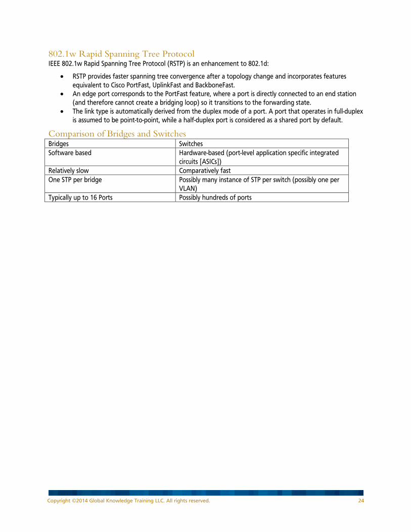
Comparison of Bridges and Switches Bridges Switches Software based Hardware-based (port-level application specific integrated
circuits [ASICs]) Relatively slow Comparatively fast One STP per bridge Possibly many instance of STP per switch (possibly one per
VLAN) Typically up to 16 Ports Possibly hundreds of ports
Copyright ©2014 Global Knowledge Training LLC. All rights reserved. 24
Half-Duplex vs. Full-Duplex Half-Duplex:
• Devices use the same pair of wire for transmit and receive, so only 50% of the bandwidth is available for sending or receiving (the same bandwidth is used to send and receive)
• Available bandwidth per device decreases as number of devices in the collision domain increases • Devices connected via hubs (Layer 1 devices) share the available bandwidth
Full-Duplex: • Uses one pair of wires for sending and another pair for receiving. • Effectively provides double the bandwidth; can send and receive at the same time. • Must be point-to-point connections, such as a PC or server-to-switch or router-to-switch. • Every device has its own collision domain on each switch port.
STP on Trunks When STP is run on trunks, there are a variety of possibilities:
• Cisco Inter-switch link (ISL) trunks use Per VLAN Spanning Tree (PVST), in which one instance of STP is run for each VLAN.
• 802.1q trunks may use common spanning tree (CST), in which one instance of STP is run for all VLANs. • Cisco 802.1q trunks use PVST+, in which one instance of STP is run for each VLAN. • 802.1s, multiple instances of spanning tree (MIST or MST, or MSTP), can also be run on 802.1q trunks.
MSTP runs one instance of STP for a group of VLANs. • On 802.1q trunks, Cisco switches support PVST+ or MSTP. • With Rapid STP, PVST+ becomes PVRST+.
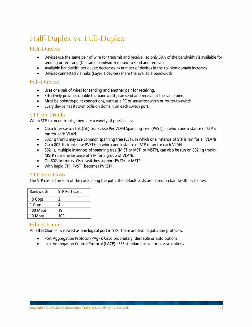
STP Port Costs The STP cost is the sum of the costs along the path; the default costs are based on bandwidth as follows: Bandwidth STP Port Cost
10 Gbps 2 1 Gbps 4 100 Mbps 19 10 Mbps 100
EtherChannel An EtherChannel is viewed as one logical port in STP. There are two negotiation protocols:
• Port Aggregation Protocol (PAgP): Cisco proprietary; desirable or auto options • Link Aggregation Control Protocol (LACP): IEEE standard; active or passive options
Copyright ©2014 Global Knowledge Training LLC. All rights reserved. 25
Routers A router maintains a routing table, which includes the destination network addresses that the router knows how to get to, and the best path to get to those destinations. The routing table may also contain a default route. A router discards packets for unknown networks.
Types of Routes Connected
• When an address and subnet mask is configured on a router’s interface, the router calculates the subnet on which that interface is on, and puts that information in the routing table as a connected route
Static • Manually configured by an administrator; each static route must be configured on each router • No overhead in processing, sending, or receiving updates • Saves bandwidth and router CPU resources • Routing table maintained by administrator
Dynamic
• A process that automatically exchanges information about available routes • Uses metrics to determine the best path to a destination network • The routing protocol must be configured on each router • Bandwidth is consumed as routing updates are transmitted between routers • Router CPU is used to process, send, and receive routing information • Memory is required to maintain related tables • Routing table maintained by routing process
Default
• Can be either static or dynamic • A router uses the default route if it does not have an explicit route that matches the destination
Routing Protocols Interior vs. Exterior Interior
• Used within a common administrative domain called an Autonomous System (AS), which is typically controlled by a single organization
• Interior routing protocols are used within a corporate network Exterior
• Used to connect Autonomous Systems • Exchanges routing information between different administrative domains • Exterior protocols are used to connect sites within a very large corporate network, or are used to
connect to the Internet
Copyright ©2014 Global Knowledge Training LLC. All rights reserved. 26
Distance Vector vs. Link State vs. Advanced Distance Vector Distance Vector
• Maintains a routing table of distance and vector (direction) to each network • Sends periodic routing updates that include the “entire” routing table at each update, to its neighbors • Received routing updates are processed, and the resulting routing table is sent by the router to its
neighbors. Thus the updates are “second-hand information” (also called routing by rumor) • Prone to routing loops (disagreement between routers) and count to infinity (routing metrics continue
to accumulate indefinitely) • Solutions to these problems include:
− Spilt Horizon: Do not send updates back out the interface through which they were learned. This eliminates back-to-back router loops.
− Define a maximum metric: eliminates count to infinity problem. − Route poisoning: Set the advertised metric to the maximum value on routes that have gone down. − Poison reverse: Overrides split horizon by informing the source of a route that it has gone down. − Hold-down timers: Eliminates long-distance loops by ignoring updates about “possibly down” routes
that have metrics worse than the current metric. − Triggered updates: Send an individual update immediately when a route is thought to be down,
rather than wait for the periodic update timer (also called flash updates).
Link State • Uses “hello” packets to establish and maintain neighbor relationships • Maintains a complete topological map (link state database [LSDB]) of the entire network, separate from
the routing table (forwarding table) • Sends updates only when necessary and only sends information that has changed, not the entire
database. Does not send information from the routing table, but rather from the database. • Routing table is individually calculated on each router from its LSDB, using the Shortest Path First (SPF)
algorithm. When SPF runs, it is CPU intensive. • The database typically requires as much memory as the routing table
Advanced Distance Vector • Uses “hello” packets to establish and maintain neighbor relationships • Sends updates only to neighbors and only when necessary; only sends information that has changed • Maintains topology table containing all of the routing information received from its neighbors.
Classless vs. Classful Classless
• Sends subnet mask with routing updates • Supports VLSM, discontiguous networks, and does not have to automatically summarize routes at a
major network boundary
Classful • Does not send subnet mask with routing updates • Does not support VLSM or discontiguous networks; automatically summarizes routes at a major network
boundary
Copyright ©2014 Global Knowledge Training LLC. All rights reserved. 27

Examples of IPv4 Routing Protocols Protocol DV or LS Internal
or External
Classless or Classful
Characteristics
Routing Information Protocol (RIP)
DV Internal RIPv1 classful; RIPv2 classless
• Sends periodic updates every 30 seconds by default
• Sends the entire routing table out every interface, minus the routes learned from that interface (split horizon)
• Uses hop count as a metric • Has a maximum reachable hop count of 15 • RIPv1 sends updates out as a broadcast • RIPv2 uses the 224.0.0.9 multicast address, and
automatically summarizes at a major network boundary, but can be configured for manual summarization
Enhanced Interior Gateway Routing Protocol (EIGRP)
Advanced DV
Internal Classless • Cisco proprietary protocol • Uses diffusing update algorithm (DUAL) • Sends triggered updates when necessary • Sends only information that has changed, not
entire routing table • Uses a composite metric consisting of
bandwidth, delay, reliability, load, and MTU; only uses bandwidth and delay by default (configurable)
• Does track hop count but only uses it as a tie-breaker
• Default maximum hop count is 224, but is configurable up to 255 maximum
• Sends updates out on a multicast address of 224.0.0.10
• In Cisco IOS 15.0 and higher does not automatically summarize at a major network boundary. Can be configured for automatic or manual summarization.
Open Shortest Path First (OSPF)
LS Internal Classless • IETF standard protocol • Sends triggered updates only when a change
occurs; also refloods updates periodically (every 30 minutes)
• Updates consist of link state advertisements (LSAs). LSAs are flooded to all routers in the area; thus routers receive the LSAs, not processed routes, as they do with distance vector protocols. LSAs are stored in LSDB.
Copyright ©2014 Global Knowledge Training LLC. All rights reserved. 28
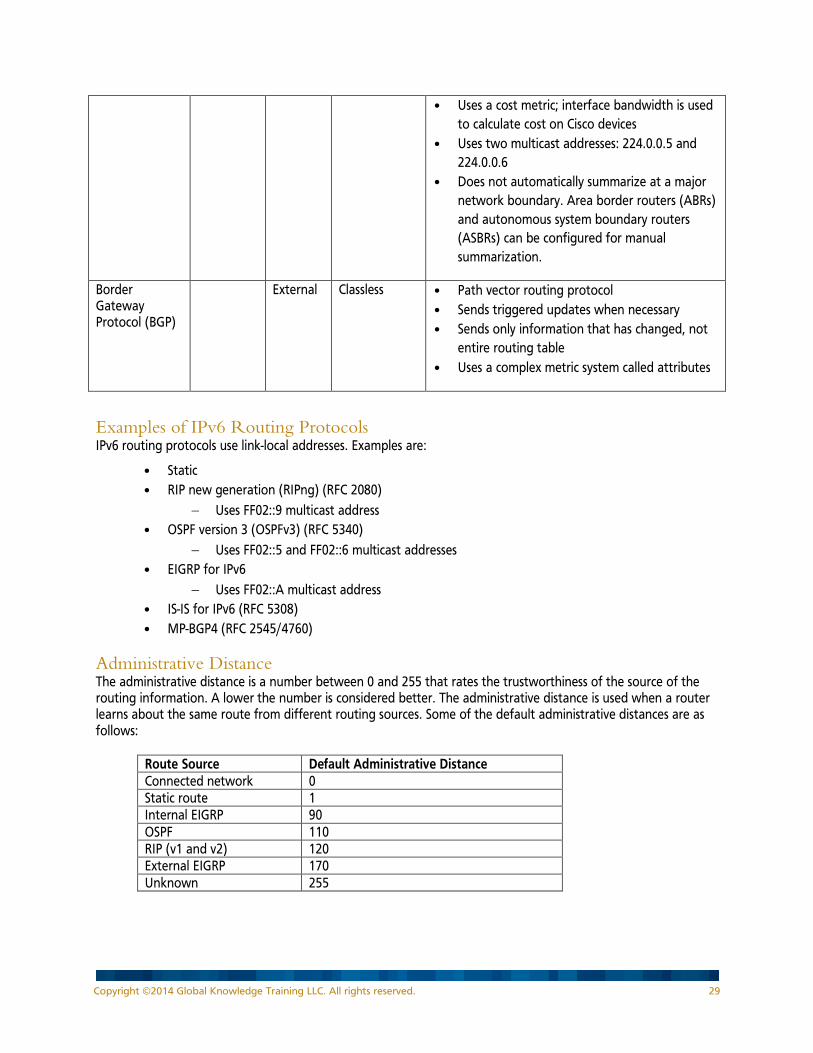
• Uses a cost metric; interface bandwidth is used to calculate cost on Cisco devices
• Uses two multicast addresses: 224.0.0.5 and 224.0.0.6
• Does not automatically summarize at a major network boundary. Area border routers (ABRs) and autonomous system boundary routers (ASBRs) can be configured for manual summarization.
Border Gateway Protocol (BGP)
External Classless • Path vector routing protocol • Sends triggered updates when necessary • Sends only information that has changed, not
entire routing table • Uses a complex metric system called attributes
Examples of IPv6 Routing Protocols IPv6 routing protocols use link-local addresses. Examples are:
• Static • RIP new generation (RIPng) (RFC 2080)
− Uses FF02::9 multicast address • OSPF version 3 (OSPFv3) (RFC 5340)
− Uses FF02::5 and FF02::6 multicast addresses • EIGRP for IPv6
− Uses FF02::A multicast address • IS-IS for IPv6 (RFC 5308) • MP-BGP4 (RFC 2545/4760)
Administrative Distance The administrative distance is a number between 0 and 255 that rates the trustworthiness of the source of the routing information. A lower the number is considered better. The administrative distance is used when a router learns about the same route from different routing sources. Some of the default administrative distances are as follows:
Route Source Default Administrative Distance Connected network 0 Static route 1 Internal EIGRP 90 OSPF 110 RIP (v1 and v2) 120 External EIGRP 170 Unknown 255
Copyright ©2014 Global Knowledge Training LLC. All rights reserved. 29
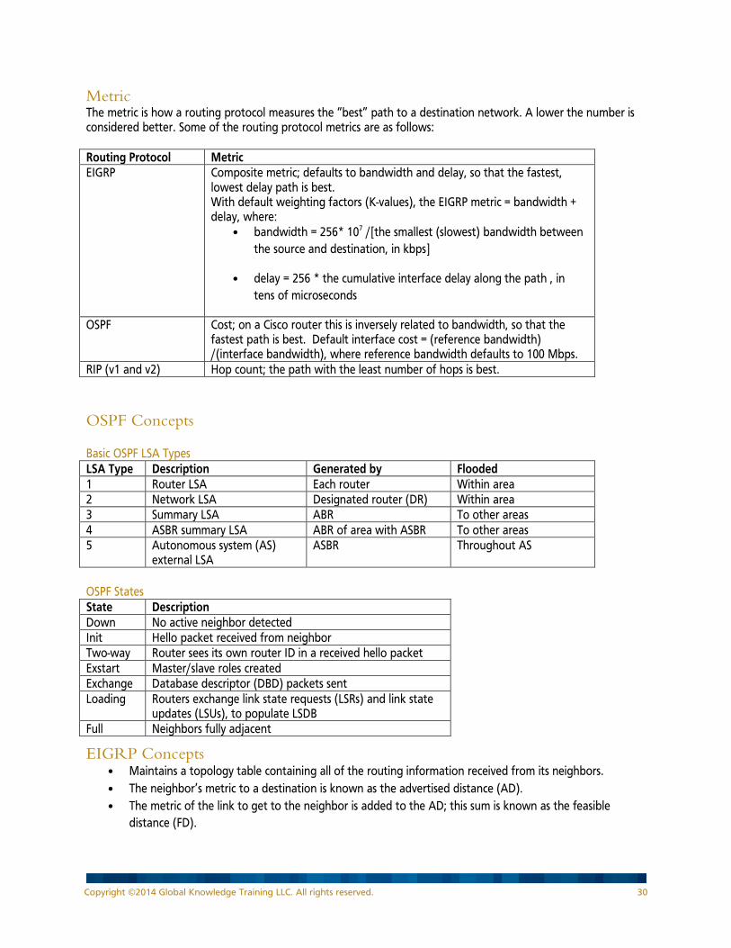
Metric The metric is how a routing protocol measures the “best” path to a destination network. A lower the number is considered better. Some of the routing protocol metrics are as follows: Routing Protocol Metric EIGRP Composite metric; defaults to bandwidth and delay, so that the fastest,
lowest delay path is best. With default weighting factors (K-values), the EIGRP metric = bandwidth + delay, where:
• bandwidth = 256* 107 /[the smallest (slowest) bandwidth between the source and destination, in kbps]
• delay = 256 * the cumulative interface delay along the path , in tens of microseconds
OSPF Cost; on a Cisco router this is inversely related to bandwidth, so that the fastest path is best. Default interface cost = (reference bandwidth) /(interface bandwidth), where reference bandwidth defaults to 100 Mbps.
RIP (v1 and v2) Hop count; the path with the least number of hops is best.
OSPF Concepts Basic OSPF LSA Types LSA Type Description Generated by Flooded 1 Router LSA Each router Within area 2 Network LSA Designated router (DR) Within area 3 Summary LSA ABR To other areas 4 ASBR summary LSA ABR of area with ASBR To other areas 5 Autonomous system (AS)
external LSA ASBR Throughout AS
OSPF States State Description Down No active neighbor detected Init Hello packet received from neighbor Two-way Router sees its own router ID in a received hello packet Exstart Master/slave roles created Exchange Database descriptor (DBD) packets sent Loading Routers exchange link state requests (LSRs) and link state
updates (LSUs), to populate LSDB Full Neighbors fully adjacent
EIGRP Concepts • Maintains a topology table containing all of the routing information received from its neighbors. • The neighbor’s metric to a destination is known as the advertised distance (AD). • The metric of the link to get to the neighbor is added to the AD; this sum is known as the feasible
distance (FD).
Copyright ©2014 Global Knowledge Training LLC. All rights reserved. 30
• DUAL is used to calculate best paths. The route with the lowest FD is the best path; it is called the “current successor” route and is offered to the routing table. The FD of the current successor becomes the metric in the routing table.
• Non-best routes that pass the “feasibility condition” are called feasible successors and can be used if the best route goes away. Feasible successors are kept in the topology table.
• The “feasibility condition” is: A route is a feasible successor if its AD is less than the FD of the current successor. This condition ensures that the EIGRP is loop-free.
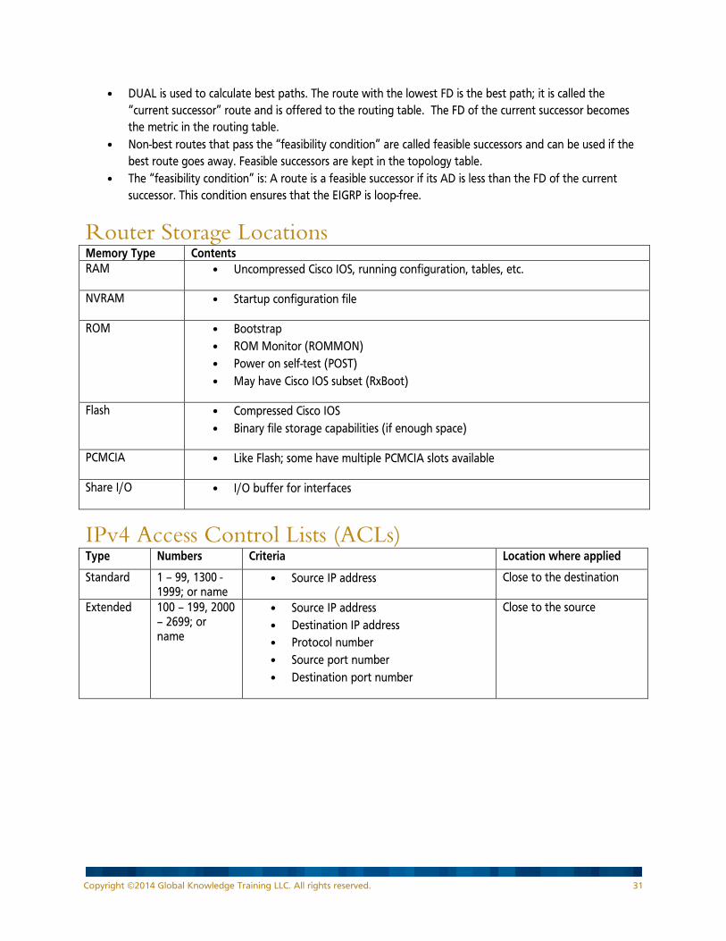
Router Storage Locations Memory Type Contents RAM • Uncompressed Cisco IOS, running configuration, tables, etc.
NVRAM • Startup configuration file
ROM • Bootstrap • ROM Monitor (ROMMON) • Power on self-test (POST) • May have Cisco IOS subset (RxBoot)
Flash • Compressed Cisco IOS • Binary file storage capabilities (if enough space)
PCMCIA • Like Flash; some have multiple PCMCIA slots available
Share I/O • I/O buffer for interfaces
IPv4 Access Control Lists (ACLs) Type Numbers Criteria Location where applied
Standard 1 – 99, 1300 -1999; or name
• Source IP address Close to the destination
Extended 100 – 199, 2000 – 2699; or name
• Source IP address • Destination IP address • Protocol number • Source port number • Destination port number
Close to the source
Copyright ©2014 Global Knowledge Training LLC. All rights reserved. 31
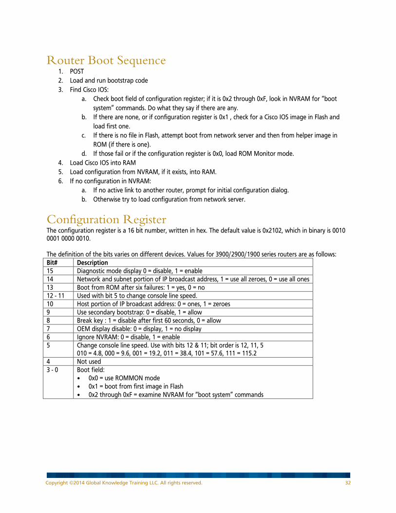
Router Boot Sequence 1. POST 2. Load and run bootstrap code 3. Find Cisco IOS:
a. Check boot field of configuration register; if it is 0x2 through 0xF, look in NVRAM for “boot system” commands. Do what they say if there are any.
b. If there are none, or if configuration register is 0x1 , check for a Cisco IOS image in Flash and load first one.
c. If there is no file in Flash, attempt boot from network server and then from helper image in ROM (if there is one).
d. If those fail or if the configuration register is 0x0, load ROM Monitor mode. 4. Load Cisco IOS into RAM 5. Load configuration from NVRAM, if it exists, into RAM. 6. If no configuration in NVRAM:
a. If no active link to another router, prompt for initial configuration dialog. b. Otherwise try to load configuration from network server.
Configuration Register The configuration register is a 16 bit number, written in hex. The default value is 0x2102, which in binary is 0010 0001 0000 0010. The definition of the bits varies on different devices. Values for 3900/2900/1900 series routers are as follows: Bit# Description 15 Diagnostic mode display 0 = disable, 1 = enable 14 Network and subnet portion of IP broadcast address, 1 = use all zeroes, 0 = use all ones 13 Boot from ROM after six failures: 1 = yes, 0 = no 12 - 11 Used with bit 5 to change console line speed. 10 Host portion of IP broadcast address: 0 = ones, 1 = zeroes 9 Use secondary bootstrap: 0 = disable, 1 = allow 8 Break key : 1 = disable after first 60 seconds, 0 = allow 7 OEM display disable: 0 = display, 1 = no display 6 Ignore NVRAM: 0 = disable, 1 = enable 5 Change console line speed. Use with bits 12 & 11; bit order is 12, 11, 5
010 = 4.8, 000 = 9.6, 001 = 19.2, 011 = 38.4, 101 = 57.6, 111 = 115.2 4 Not used 3 - 0 Boot field:
• 0x0 = use ROMMON mode • 0x1 = boot from first image in Flash • 0x2 through 0xF = examine NVRAM for “boot system” commands
Copyright ©2014 Global Knowledge Training LLC. All rights reserved. 32

Network Address Translation NAT Addresses NAT address types are:
• Inside local: The address assigned to a device on the “inside” network. This is typically a private address.
• Inside global: The address of a device on the “inside” network as it appears to devices on the “outside” network. This is typically a public address. For example, the inside local address 10.1.1.1 may be translated to the inside global address 209.165.201.1.
• Outside global: The address assigned to a device on the “outside” network. • Outside local: The address of a device on the “outside” network as it appears to devices on the
“inside” network. The outside global address may be translated to the outside local address, but typically translation is not done and these addresses are identical.
Types of NAT There are three types of NAT:
• Static NAT: one-to-one • Dynamic NAT: many-to-many (using a pool) • Port address translation (PAT): many-to-one (using overloading)
First Hop Redundancy Protocols Three first hop redundancy protocols:
• Hot Standby Router Protocol (HSRP): Cisco proprietary • Gateway Load Balancing Protocol (GLBP): Cisco proprietary • Virtual Router Redundancy Protocol (VRRP): IETF standard
Network Management Syslog Severity Levels Syslog severity levels are:
0: emergency 1: alert 2: critical 3: error 4: warning 5: notification 6: informational 7: debugging
NetFlow Flow A NetFlow flow is a unidirectional sequence of packets with the following seven key fields identical:
• Source and destination IP addresses • Source and destination port numbers • Protocol type • Type of service • Input logical interface
Copyright ©2014 Global Knowledge Training LLC. All rights reserved. 33

Virtual Private Networks (VPNs) Types of VPNs Two types of VPNs:
• Site-to-site: connect networks together • Remote access (for example, Cisco AnyConnect and Cisco SSL VPN ): connect individual hosts to a
corporate network
IP Security (IPSec) IPSec is a framework that allows choices of many protocols depending on the features required. IPSec provides:
• Confidentiality: ensures only authorized devices can read the data sent • Integrity: ensures data is not changed during transmission • Authentication: ensures a device is communicating with an authorized device • Anti-replay protection: verifies that each packet is unique and has not been duplicated.
Generic Routing Encapsulation (GRE) Tunnels GRE:
• Cisco proprietary tunneling protocol • IP protocol number 47 • Three protocols involved:
− Passenger protocol: protocol being encapsulated − Carrier protocol: in this case, GRE − Transport protocol: protocol that carries the passenger protocol
Cisco IOS Command Line Interface (CLI) and Commands Notes:
• In each of the following tables, the commands are listed in alphabetical order. • Many of the commands can be used on routers and switches. • Most commands have many parameters. In the following tables only a few of the parameters are
shown. Refer to the Command Reference documentation on Cisco’s web site for the full command syntax.
Cisco IOS EXEC Operating Modes Mode Prompt Sample Functions User Router> Read-only privileges; for example to examine interface status and
examine router status Privileged Router# Full privileges to read, write, modify, copy, and delete; for example to
examine interface status, examine router status, and examine configuration, and copy configuration to device
Configuration Router(config)# Modify the running configuration
Copyright ©2014 Global Knowledge Training LLC. All rights reserved. 34

General Commands Command Meaning ? Help <control> <a> Move to the beginning of the command line <control> <b> or <left arrow> Move backward one character <control> <c> Abort from setup mode <control> <d> or <backspace> Removes one character to the left of the cursor <control> <e> Move to the end of the command line <control> <f> or <right arrow> Move forward one character <control> <n> or <down arrow> Last (previous) command recall <control> <p> or <up arrow> More recent command recall <control> <shift> <6> Interrupt a Cisco IOS process, such as a ping or traceroute <control> <shift> <6>, followed by <x> The “escape sequence”, used to suspend a Telnet or SSH session <control> <r> Redisplays a line <control> <u> Erases a line from the beginning of line <control> <w> Erases a word <control> <z> Exit from configuration mode back to privileged EXEC mode <Esc> <B> Move to the beginning of the previous word <Esc> <F> Move forward one word <enter> Resumes the last suspended telnet session <tab> key Keyword completion Router#auto secure Initiates a security audit and recommends changes for fixing security
vulnerabilities Router#clear counters Resets the “show interface” counters to zero Router#clear line Disconnects a telnet session from a foreign host Router#clock set Sets the device’s clock Router#configure terminal Enters configuration mode Router#connect Logs on to a host that supports Telnet, rlogin, or LAT Router#copy flash0: tftp: Copies a file from Flash memory to a TFTP server Router#copy running-config startup-config
Copies configuration from RAM to NVRAM (overwrites)
Router#copy running-config tftp: Copies configuration from RAM to TFTP server (overwrites) Router#copy startup-config running-config
Executes configuration from NVRAM into RAM (executes line-by-line, merges, does not overwrite)
Router#copy startup-config tftp: Copies configuration from NVRAM to TFTP server (overwrites) Router#copy tftp: flash0: Copies a file from a TFTP server to Flash memory Router#copy tftp: running-config Copies configuration from TFTP server into RAM (executes line-by-line,
merges, does not overwrite) Router#copy tftp: startup-config Copies configuration from TFTP server to NVRAM (overwrites) Router#debug Starts the console display of the events on the device Router#disable Exit privileged EXEC mode Router#disconnect Disconnect a telnet session Router>enable Enter privileged mode Router#erase startup-config Erases the configuration in NVRAM Router#exit Exit from the device Router#license boot module Installs an evaluation license Router#license clear Clears a license Router#license install Installs a license
Copyright ©2014 Global Knowledge Training LLC. All rights reserved. 35
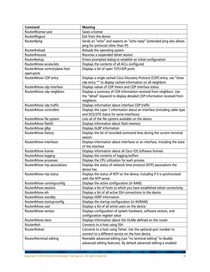
Command Meaning Router#license save Saves a license Router#logout Exit from the device Router#ping Sends an “echo” and expects an “echo reply” (extended ping also allows
ping for protocols other than IP) Router#reload Reloads the operating system Router#resume Resumes a suspended telnet session Router#setup Enters prompted dialog to establish an initial configuration Router#show access-lists Displays the contents of all ACLs configured Router#show control-plane host open-ports
Displays a list of open TCP/UDP ports
Router#show CDP entry Displays a single cached Cisco Discovery Protocol (CDP) entry; use “show cdp entry *” to display cached information on all neighbors
Router#show cdp interface Displays values of CDP timers and CDP interface status Router#show cdp neighbors Displays a summary of CDP information received from neighbors. Use
the “detail” keyword to display detailed CDP information received from neighbors.
Router#show cdp traffic Displays information about interface CDP traffic Router#show controllers Displays the Layer 1 information about an interface (including cable type
and DCE/DTE status for serial interfaces) Router#show file system Lists all of the file systems available on the device Router#show flash0: Displays information about flash memory Router#show glbp Displays GLBP information Router#show history Displays the list of recorded command lines during the current terminal
session Router#show interfaces Displays information about interfaces or an interface, including the state
of the interface Router#show license Displays information about all Cisco IOS Software licenses Router#show logging Displays the contents of logging buffers Router#show processes Displays the CPU utilization for each process Router#show ntp associations Displays the status of network time protocol (NTP) associations the
device has Router#show ntp status Displays the status of NTP on the device, including if it is synchronized
with the NTP server Router#show running-config Displays the active configuration (in RAM) Router#show sessions Displays a list of hosts to which you have established telnet connectivity Router#show ssh Displays a list of all active SSH connections to the device Router#show standby Displays HSRP information Router#show startup-config Displays the startup configuration (in NVRAM) Router#show user Displays a list of all active users on the device Router#show version Displays configuration of system hardware, software version, and
configuration register value Router#show vlans Displays information about the VLANs defined on the router Router#ssh Connects to a host using SSH Router#telnet Connects to a host using Telnet. Use the optional port number to
connect to a different service on the host device. Router#terminal editing Reenable advanced editing (use “no terminal editing” to disable
advanced editing features). By default advanced editing is enabled
Copyright ©2014 Global Knowledge Training LLC. All rights reserved. 36
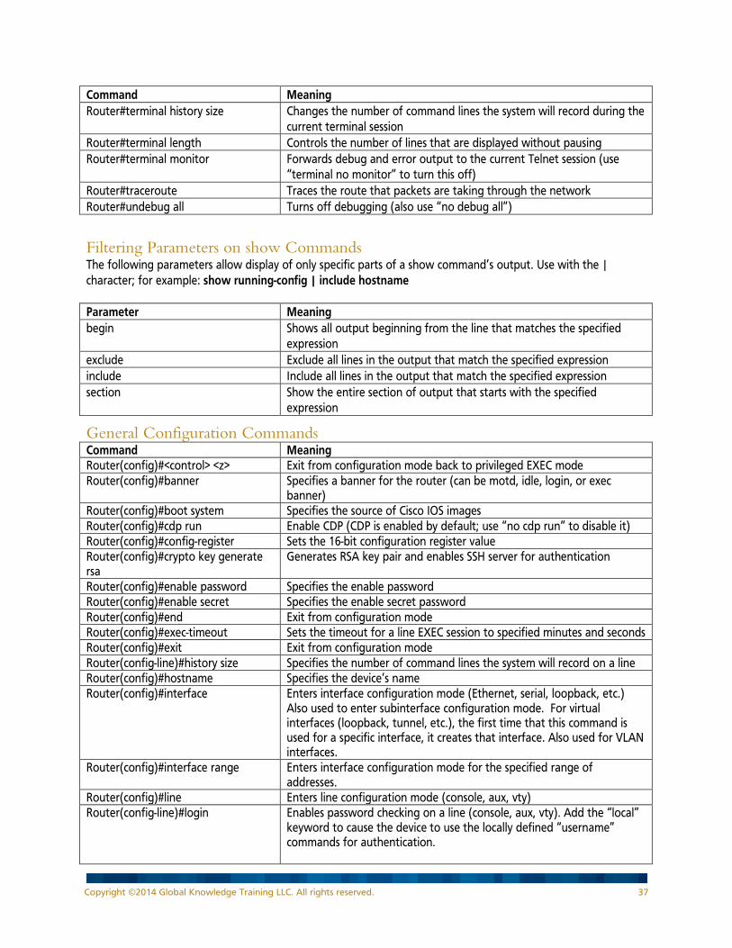
Command Meaning Router#terminal history size Changes the number of command lines the system will record during the
current terminal session Router#terminal length Controls the number of lines that are displayed without pausing Router#terminal monitor Forwards debug and error output to the current Telnet session (use
“terminal no monitor” to turn this off) Router#traceroute Traces the route that packets are taking through the network Router#undebug all Turns off debugging (also use “no debug all”)
Filtering Parameters on show Commands The following parameters allow display of only specific parts of a show command’s output. Use with the | character; for example: show running-config | include hostname Parameter Meaning begin Shows all output beginning from the line that matches the specified
expression exclude Exclude all lines in the output that match the specified expression include Include all lines in the output that match the specified expression section Show the entire section of output that starts with the specified
expression
General Configuration Commands Command Meaning Router(config)#<control> <z> Exit from configuration mode back to privileged EXEC mode Router(config)#banner Specifies a banner for the router (can be motd, idle, login, or exec
banner) Router(config)#boot system Specifies the source of Cisco IOS images Router(config)#cdp run Enable CDP (CDP is enabled by default; use “no cdp run” to disable it) Router(config)#config-register Sets the 16-bit configuration register value Router(config)#crypto key generate rsa
Generates RSA key pair and enables SSH server for authentication
Router(config)#enable password Specifies the enable password Router(config)#enable secret Specifies the enable secret password Router(config)#end Exit from configuration mode Router(config)#exec-timeout Sets the timeout for a line EXEC session to specified minutes and seconds Router(config)#exit Exit from configuration mode Router(config-line)#history size Specifies the number of command lines the system will record on a line Router(config)#hostname Specifies the device’s name Router(config)#interface Enters interface configuration mode (Ethernet, serial, loopback, etc.)
Also used to enter subinterface configuration mode. For virtual interfaces (loopback, tunnel, etc.), the first time that this command is used for a specific interface, it creates that interface. Also used for VLAN interfaces.
Router(config)#interface range Enters interface configuration mode for the specified range of addresses.
Router(config)#line Enters line configuration mode (console, aux, vty) Router(config-line)#login Enables password checking on a line (console, aux, vty). Add the “local”
keyword to cause the device to use the locally defined “username” commands for authentication.
Copyright ©2014 Global Knowledge Training LLC. All rights reserved. 37
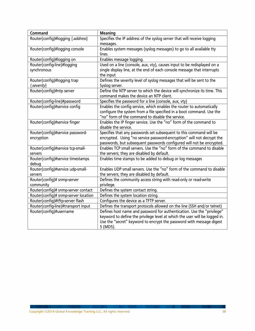
Command Meaning Router(config)#logging {address} Specifies the IP address of the syslog server that will receive logging
messages. Router(config)#logging console Enables system messages (syslog messages) to go to all available tty
lines. Router(config)#logging on Enables message logging. Router(config-line)#logging synchronous
Used on a line (console, aux, vty), causes input to be redisplayed on a single display line, at the end of each console message that interrupts the input
Router(config)#logging trap {severity}
Defines the severity level of syslog messages that will be sent to the Syslog server.
Router(config)#ntp server Define the NTP server to which the device will synchronize its time. This command makes the device an NTP client.
Router(config-line)#password Specifies the password for a line (console, aux, vty) Router(config)#service config Enables the config service, which enables the router to automatically
configure the system from a file specified in a boot command. Use the “no” form of the command to disable the service.
Router(config)#service finger Enables the IP finger service. Use the “no” form of the command to disable the service.
Router(config)#service password-encryption
Specifies that any passwords set subsequent to this command will be encrypted. Using “no service password-encryption” will not decrypt the passwords, but subsequent passwords configured will not be encrypted.
Router(config)#service tcp-small-servers
Enables TCP small servers. Use the “no” form of the command to disable the servers; they are disabled by default.
Router(config)#service timestamps debug
Enables time stamps to be added to debug or log messages
Router(config)#service udp-small-servers
Enables UDP small servers. Use the “no” form of the command to disable the servers; they are disabled by default.
Router(config)# snmp-server community
Defines the community access string with read-only or read-write privilege.
Router(config)# snmp-server contact Defines the system contact string. Router(config)# snmp-server location Defines the system location string. Router(config)#tftp-server flash Configures the device as a TFTP server. Router(config-line)#transport input Defines the transport protocols allowed on the line (SSH and/or telnet) Router(config)#username Defines host name and password for authentication. Use the “privilege”
keyword to define the privilege level at which the user will be logged in. Use the “secret” keyword to encrypt the password with message digest 5 (MD5).
Copyright ©2014 Global Knowledge Training LLC. All rights reserved. 38

Interface Configuration Commands Command Meaning Router(config-if)#cdp enable Enable CDP on an interface (CDP is enabled by default; use “no cdp
enable” to disable it) Router(config-if)#clock rate Sets clock rate in bps (used on DCE interfaces) Router(config-if)#description Adds a text description to the interface Router(config-subif)# encapsulation dot1q {vlan-number}
Defines the data-link encapsulation and VLAN number for a subinterface; used for inter-VLAN routing on a subinterface
Router(config-if)#interface Enters interface configuration mode (or sub-interface mode if already in interface mode)
Router(config-if)#interface type.subinterface number {point-to-point | multipoint}
Enters sub-interface configuration mode on a frame relay interface
Router(config-if)#media-type On Cisco routers with more than one connector for an Ethernet interface, selects the media-type connector for the Ethernet interface (for example, use “10baset” for RJ-45 connectors)
Router(config-if)#shutdown Administratively shutdown an interface (use “no shutdown” to bring the interface up)
Router(config-if)#standby group ip address
Activates HSRP on the interface, in the specified group. The address is the address of the HSRP virtual router that is created.
Router(config-if)#tunnel destination Configures the specified IP address as the destination address for packets sent on the tunnel interface
Router(config-if)#tunnel mode Configures the specified mode on the tunnel interface Router(config-if)#tunnel source Configures the specified IP address as the source address for packets
sent on the tunnel interface
Copyright ©2014 Global Knowledge Training LLC. All rights reserved. 39

General Switch Commands Command Meaning Switch#debug spanning-tree switch state Starts the console display of STP port state changes Switch#debug spanning-tree pvst+ Starts the console display of PVST+ events Switch#show dtp interface Displays the dynamic trunking protocol (DTP) parameters of the
interface Switch#show etherchannel port-channel Displays EtherChannel port-channel information Switch#show etherchannel summary Displays a summary of the channel groups Switch#show interfaces port-channel Displays status of the specified port-channel interface Switch#show interfaces switchport Displays the switchport parameters of the interface Switch#show interfaces trunk Displays the trunk parameters of the interface Switch#show mac address-table Displays the switch’s MAC address table Switch#show port-security Displays the port security status (can also specify an interface or an
address) Switch#show spanning-tree Displays the details of the spanning-tree for each VLAN defined on
the switch. Use the “vlan” keyword to display information about the spanning-tree on a VLAN.
Switch#show vlan Displays information about the VLANs defined on the switch. Use the “id” keyword followed by a VLAN number to display information for the specified VLAN. Use the “brief” keyword to display one line of information about each defined VLAN.
General Switch Configuration Commands Command Meaning Switch(config)#interface port-channel Enters interface configuration mode for the EtherChannel specified Switch(config)#ip default-gateway Defines the address of the default gateway (which is the address of a
router) Switch(config)#spanning-tree mode rapid-pvst
Configures PVRST+ on the switch.
Switch(config)#spanning-tree portfast bpduguard default
Configures BPDU guard on all PortFast-enabled interfaces on the switch
Switch(config)#spanning-tree portfast default
Configures PortFast on all of the interfaces on the switch.
Switch(config)#spanning-tree vlan {number} root primary
Configures the switch to be the primary root bridge for the specified vlan
Switch(config)#spanning-tree vlan {number} root secondary
Configures the switch to be the secondary root bridge for the specified vlan
Switch(config)#vlan Defines a VLAN and enters VLAN configuration mode Switch(config)#vtp mode Defines the VTP mode of the switch Switch(config-vlan)#name Defines the name of the VLAN
Copyright ©2014 Global Knowledge Training LLC. All rights reserved. 40

Switch Interface Configuration Commands Command Meaning Switch(config-if)#channel-group {number} mode
Configures the interface as part of the port-channel with the specified number, using the specified mode
Switch(config-if)#duplex Sets the duplex mode of the interface Switch(config-if)#spanning-tree bpduguard enable
Enables the BPDU guard feature on the interface
Switch(config-if)#spanning-tree portfast
Configures PortFast on the interface.
Switch(config-if)#speed Sets the speed of an interface with configurable speed Switch(config-if)#switchport access vlan
Sets VLAN assignment of an interface
Switch(config-if)#switchport mode Defines the mode of the switch interface (access, trunk, dynamic desirable, dynamic auto)
Switch(config-if)#switchport nonegotiate
Specifies that DTP negotiation frames are not sent on the interface
Switch(config-if)#switchport port-security
Enables port-security on the interface. Use other options on this command to configure the MAC address (or use sticky MAC address configuration), define the maximum number of secure MAC addresses, and define the violation mode.
Switch(config-if)#switchport trunk allowed vlan
Sets list of allowed VLANs on a trunk interface.
Switch(config-if)#switchport trunk native vlan
Defines the native VLAN on the trunk
General IP Commands Command Meaning Router#debug eigrp packets Starts the console display of EIGRP packets sent and received (good for
debugging EIGRP authentication) Router#debug ip eigrp Starts the console display of IP-EIGRP packets sent and received Router#debug ip ospf adj Starts the console display of OSPF adjacency-related events (good for
debugging OSPF authentication) Router#debug ip ospf events Starts the console display of the OSPF-related events Router#debug ip ospf packet Starts the console display of each OSPF packet received Router#debug ip rip Starts the console display of the IP RIP-related events on the router Router#show hosts Displays the cached list of host names and addresses (both static and
obtained from a DNS server) Router#show ip access-list Displays the IP ACLs configured Router#show ip arp Displays the ARP table on the device Router#show ip cache flow Displays a summary of NetFlow information. Router#show ip flow export Displays NetFlow export information Router#show ip interface Displays IP-specific information about an interface, including if access-lists
are applied; with the “brief” keyword, displays a summary of interface info.
Router#show ip eigrp interfaces Displays EIGRP interface details Router#show ip eigrp neighbors Displays the EIGRP neighbors table Router#show ip eigrp topology Displays the EIGRP topology table Router#show ip eigrp traffic Displays the EIGRP traffic statistics Router#show ip ospf Displays OSPF timers and other statistics, including the number of times
the SPF algorithm has run. Router#show ip ospf interface Displays OSPF interface details Router#show ip ospf neighbor Displays the OSPF neighbors table
Copyright ©2014 Global Knowledge Training LLC. All rights reserved. 41

Command Meaning Router#show ip protocols Displays the details of the IP routing protocols that are running Router#show ip route Displays the IP routing table; use other keywords to display specific parts
of the routing table Router#show ip ssh Displays IP SSH details on the device
IP Configuration Commands Command Meaning Router(config-router)#area {number} authentication
Enables OSPF plaintext authentication for the area. (Use other parameters for null or MD5 authentication.)
Router(config-router)#auto-cost reference-bandwidth
Changes the reference bandwidth used in the OSPF cost calculation.
Router(config-router)#auto-summary Enables automatic summarization of routes at major network boundaries, for RIPv2 and EIGRP. Use the “no” form of the command to disable this feature.
Router(config-router)#default-information originate
Generates a default external route into an OSPF routing domain; add the “always” keyword to specify that OSPF always advertises the default route regardless of whether the router has a default route in its own routing table.
Router(config-if)#ip address Assigns an IP address and subnet mask to an interface. Use the “dhcp” option to specify that the interface obtains its address via DHCP.
Router(config-if)#ip authentication key-chain eigrp
Defines the key chain to use for EIGRP MD5 authentication on the interface
Router(config-if)#ip authentication mode eigrp
Enables EIGRP MD5 authentication on the interface
Router(config)#ip classless Specifies that if a packet is received with a destination address within an unknown subnet of a directly attached network, the router will match it to the default route and forward it to the next hop specified by the default route.
Router(config)#ip domain-lookup Turns on name service (DNS) lookups (use “no ip domain-lookup” to turn off DNS lookup)
Router(config)#ip domain-name Defines a host domain for device Router(config-if)#ip flow Enables NetFlow on an interface Router(config)#ip flow-export destination
Defines destination for NetFlow export information
Router(config)#ip flow-export version Defines version (format) of NetFlow export information Router(config)#ip host name address Defines a static local host name to IP address mapping Router(config)#ip http secure-server Enables HTTPS server on the device Router(config)#ip http server Enables HTTP server on the device. Use the “no” form of the command
to disable the HTTP server. Router(config)#ip name-server Defines one or more (up to 6) hosts that supply host name information
(DNS). The address can be either an IPv4 or IPv6 address. Router(config-if)#ip ospf {process-number} area {area-number)
Enables OSPF on the interface and defines which area it will run in. Allows the router to advertise the subnet to which the interface belongs.
Router(config-if)#ip ospf authentication
Enables OSPF plaintext authentication on the interface. (Use other parameters for null or MD5 authentication.)
Router(config-if)#ip ospf authentication-key
Defines the OSPF authentication key for plaintext authentication
Router(config-if)#ip ospf cost Defines the OSPF cost of the interface
Copyright ©2014 Global Knowledge Training LLC. All rights reserved. 42
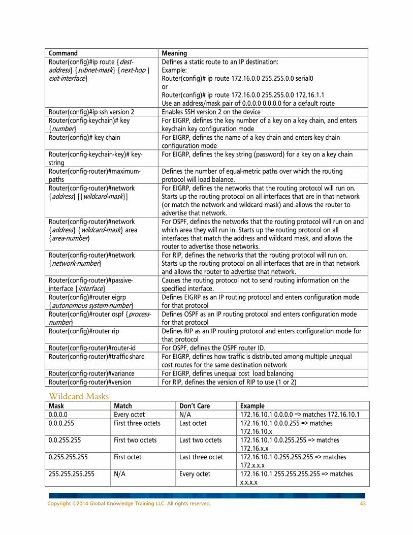
Command Meaning Router(config)#ip route {dest-address} {subnet-mask} {next-hop | exit-interface}
Defines a static route to an IP destination: Example: Router(config)# ip route 172.16.0.0 255.255.0.0 serial0 or Router(config)# ip route 172.16.0.0 255.255.0.0 172.16.1.1 Use an address/mask pair of 0.0.0.0 0.0.0.0 for a default route
Router(config)#ip ssh version 2 Enables SSH version 2 on the device Router(config-keychain)# key {number}
For EIGRP, defines the key number of a key on a key chain, and enters keychain key configuration mode
Router(config)# key chain For EIGRP, defines the name of a key chain and enters key chain configuration mode
Router(config-keychain-key)# key-string
For EIGRP, defines the key string (password) for a key on a key chain
Router(config-router)#maximum-paths
Defines the number of equal-metric paths over which the routing protocol will load balance.
Router(config-router)#network {address} [{wildcard-mask}]
For EIGRP, defines the networks that the routing protocol will run on. Starts up the routing protocol on all interfaces that are in that network (or match the network and wildcard mask) and allows the router to advertise that network.
Router(config-router)#network {address} {wildcard-mask} area {area-number)
For OSPF, defines the networks that the routing protocol will run on and which area they will run in. Starts up the routing protocol on all interfaces that match the address and wildcard mask, and allows the router to advertise those networks.
Router(config-router)#network {network-number}
For RIP, defines the networks that the routing protocol will run on. Starts up the routing protocol on all interfaces that are in that network and allows the router to advertise that network.
Router(config-router)#passive-interface {interface}
Causes the routing protocol not to send routing information on the specified interface.
Router(config)#router eigrp {autonomous system-number}
Defines EIGRP as an IP routing protocol and enters configuration mode for that protocol
Router(config)#router ospf {process-number}
Defines OSPF as an IP routing protocol and enters configuration mode for that protocol
Router(config)#router rip Defines RIP as an IP routing protocol and enters configuration mode for that protocol
Router(config-router)#router-id For OSPF, defines the OSPF router ID. Router(config-router)#traffic-share For EIGRP, defines how traffic is distributed among multiple unequal
cost routes for the same destination network Router(config-router)#variance For EIGRP, defines unequal cost load balancing Router(config-router)#version For RIP, defines the version of RIP to use (1 or 2)
Wildcard Masks Mask Match Don’t Care Example 0.0.0.0 Every octet N/A 172.16.10.1 0.0.0.0 => matches 172.16.10.1 0.0.0.255 First three octets Last octet 172.16.10.1 0.0.0.255 => matches
172.16.10.x 0.0.255.255 First two octets Last two octets 172.16.10.1 0.0.255.255 => matches
172.16.x.x 0.255.255.255 First octet Last three octet 172.16.10.1 0.255.255.255 => matches
172.x.x.x 255.255.255.255 N/A Every octet 172.16.10.1 255.255.255.255 => matches
x.x.x.x
Copyright ©2014 Global Knowledge Training LLC. All rights reserved. 43
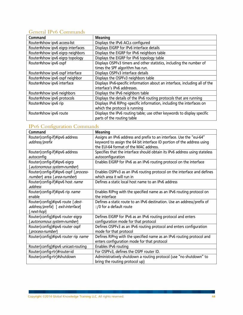
General IPv6 Commands Command Meaning Router#show ipv6 access-list Displays the IPv6 ACLs configured Router#show ipv6 eigrp interfaces Displays EIGRP for IPv6 interface details Router#show ipv6 eigrp neighbors Displays the EIGRP for IPv6 neighbors table Router#show ipv6 eigrp topology Displays the EIGRP for IPv6 topology table Router#show ipv6 ospf Displays OSPFv3 timers and other statistics, including the number of
times the SPF algorithm has run. Router#show ipv6 ospf interface Displays OSPFv3 interface details Router#show ipv6 ospf neighbor Displays the OSPFv3 neighbors table Router#show ipv6 interface Displays IPv6-specific information about an interface, including all of the
interface’s IPv6 addresses. Router#show ipv6 neighbors Displays the IPv6 neighbors table Router#show ipv6 protocols Displays the details of the IPv6 routing protocols that are running Router#show ipv6 rip Displays IPv6 RIPng -specific information, including the interfaces on
which the protocol is running Router#show ipv6 route Displays the IPv6 routing table; use other keywords to display specific
parts of the routing table
IPv6 Configuration Commands Command Meaning Router(config-if)#ipv6 address address/prefix
Assigns an IPv6 address and prefix to an interface. Use the “eui-64” keyword to assign the 64 bit interface ID portion of the address using the EUI-64 format of the MAC address.
Router(config-if)#ipv6 address autoconfig
Specifies that the interface should obtain its IPv6 address using stateless autoconfiguration
Router(config-if)#ipv6 eigrp {autonomous system-number}
Enables EIGRP for IPv6 as an IPv6 routing protocol on the interface
Router(config-if)#ipv6 ospf {process-number} area {area-number)
Enables OSPFv3 as an IPv6 routing protocol on the interface and defines which area it will run in
Router(config-if)#ipv6 host name address
Defines a static local host name to an IPv6 address
Router(config-if)#ipv6 rip name enable
Enables RIPng with the specified name as an IPv6 routing protocol on the interface
Router(config)#ipv6 route {dest-address/prefix} [ exit-interface] {next-hop}
Defines a static route to an IPv6 destination. Use an address/prefix of ::/0 for a default route
Router(config)#ipv6 router eigrp {autonomous system-number}
Defines EIGRP for IPv6 as an IPv6 routing protocol and enters configuration mode for that protocol
Router(config)#ipv6 router ospf {process-number}
Defines OSPFv3 as an IPv6 routing protocol and enters configuration mode for that protocol
Router(config)#ipv6 router rip name Defines RIPng with the specified name as an IPv6 routing protocol and enters configuration mode for that protocol
Router(config)#ipv6 unicast-routing Enables IPv6 routing Router(config-rtr)#router-id For OSPFv3, defines the OSPF router ID. Router(config-rtr)#shutdown Administratively shutdown a routing protocol (use “no shutdown” to
bring the routing protocol up)
Copyright ©2014 Global Knowledge Training LLC. All rights reserved. 44
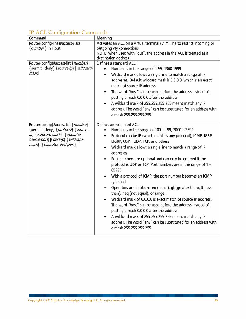
IP ACL Configuration Commands Command Meaning Router(config-line)#access-class {number } in | out
Activates an ACL on a virtual terminal (VTY) line to restrict incoming or outgoing vty connections. NOTE: when used with “out”, the address in the ACL is treated as a destination address
Router(config)#access-list {number} {permit |deny} {source-ip} [ wildcard-mask]
Defines a standard ACL: • Number is in the range of 1-99, 1300-1999 • Wildcard mask allows a single line to match a range of IP
addresses. Default wildcard mask is 0.0.0.0, which is an exact match of source IP address
• The word “host” can be used before the address instead of putting a mask 0.0.0.0 after the address
• A wildcard mask of 255.255.255.255 means match any IP address. The word “any” can be substituted for an address with a mask 255.255.255.255
Router(config)#access-list {number} {permit |deny} {protocol} {source-ip} {wildcard-mask} [{operator source-port}]{dest-ip} {wildcard-mask} [{operator dest-port}
Defines an extended ACL: • Number is in the range of 100 – 199, 2000 – 2699 • Protocol can be IP (which matches any protocol), ICMP, IGRP,
EIGRP, OSPF, UDP, TCP, and others • Wildcard mask allows a single line to match a range of IP
addresses • Port numbers are optional and can only be entered if the
protocol is UDP or TCP. Port numbers are in the range of 1 – 65535
• With a protocol of ICMP, the port number becomes an ICMP type code
• Operators are boolean: eq (equal), gt (greater than), lt (less than), neq (not equal), or range.
• Wildcard mask of 0.0.0.0 is exact match of source IP address. The word “host” can be used before the address instead of putting a mask 0.0.0.0 after the address
• A wildcard mask of 255.255.255.255 means match any IP address. The word “any” can be substituted for an address with a mask 255.255.255.255
Copyright ©2014 Global Knowledge Training LLC. All rights reserved. 45
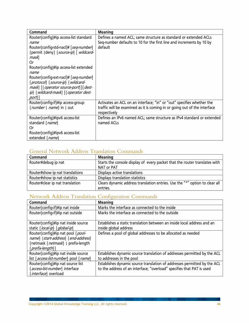
Command Meaning Router(config)#ip access-list standard name Router(config-std-nacl)# [seq-number] {permit |deny} {source-ip} [ wildcard-mask] Or Router(config)#ip access-list extended name Router(config-ext-nacl)# [seq-number] {protocol} {source-ip} {wildcard-mask} [{operator source-port}]{dest-ip} {wildcard-mask} [{operator dest-port}]
Defines a named ACL; same structure as standard or extended ACLs Seq-number defaults to 10 for the first line and increments by 10 by default
Router(config-if)#ip access-group {number | name} in | out
Activates an ACL on an interface; “in” or “out” specifies whether the traffic will be examined as it is coming in or going out of the interface respectively
Router(config)#ipv6 access-list standard {name} Or Router(config)#ipv6 access-list extended {name}
Defines an IPv6 named ACL; same structure as IPv4 standard or extended named ACLs
General Network Address Translation Commands Command Meaning Router#debug ip nat Starts the console display of every packet that the router translates with
NAT or PAT Router#show ip nat translations Displays active translations Router#show ip nat statistics Displays translation statistics Router#clear ip nat translation Clears dynamic address translation entries. Use the “*” option to clear all
entries.
Network Address Translation Configuration Commands Command Meaning Router(config-if)#ip nat inside Marks the interface as connected to the inside Router(config-if)#ip nat outside
Marks the interface as connected to the outside
Router(config)#ip nat inside source static {local-ip} {global-ip}
Establishes a static translation between an inside local address and an inside global address
Router(config)#ip nat pool {pool-name} {start-address} {end-address} {netmask {netmask} | prefix-length {prefix-length}}
Defines a pool of global addresses to be allocated as needed
Router(config)#ip nat inside source list {access-list-number} pool {name}
Establishes dynamic source translation of addresses permitted by the ACL to addresses in the pool
Router(config)#ip nat source list {access-list-number} interface {interface} overload
Establishes dynamic source translation of addresses permitted by the ACL to the address of an interface; “overload” specifies that PAT is used
Copyright ©2014 Global Knowledge Training LLC. All rights reserved. 46

General DHCP Commands Command Meaning Router#show dhcp lease Displays DHCP addresses that are leased from a DHCP server Router#show ip dhcp bindings Displays DHCP IP-to-MAC address bindings Router#show ip dhcp conflicts Displays DHCP address conflicts Router#show ip dhcp pool Displays DHCP pool parameters
DHCP Configuration Commands Command Meaning Router(dhcp-config)#default-router Defines the DHCP pool default router Router(dhcp-config)#dns-server Defines the DHCP pool DNS server Router(dhcp-config)#domain-name Defines the DHCP pool domain name Router(dhcp-config)#lease Defines the DHCP pool lease in days Router(config)#ip dhcp excluded-address
Defines the addresses that are to be excluded from DHCP pools
Router(config)#ip dhcp pool Defines the DHCP pool name and enters DHCP configuration mode Router(config-if)#ip helper-address Enables forwarding of broadcasts that are received on the interface to
the specified IP address. Router(dhcp-config)#network Defines the DHCP pool network number
General WAN Commands Command Meaning Router#clear frame-relay inarp Clears dynamically created Frame Relay maps, which are created by the
use of Inverse ARP Router#debug frame-relay lmi Starts the console display of LMI packets between the router and the
Frame Relay switch Router#debug ppp authentication Starts the console display of the PPP authentication – related events on
the router Router#debug ppp negotiation Starts the console display of the PPP negotiation – related events on the
router Router#show frame-relay lmi Displays the LMI traffic statistics Router#show frame-relay map Displays the mapping between network layer addresses and DLCIs, both
static and dynamic Router#show frame-relay pvc Displays the status of each configured PVC as well as traffic statistics
WAN Configuration Commands Command Meaning Router(config-if)#bandwidth Defines the bandwidth (in kilobits per second) of the interface (used in
routing protocol calculations) Router(config-if)#encapsulation Defines the data-link encapsulation for an interface (PPP, HLDC, frame-
relay) Router(config-subif)#frame-relay interface-dlci
Assigns a DLCI to the subinterface (only used on frame relay subinterfaces
Router(config-if)#frame-relay inverse-arp
Enables inverse ARP on an interface (only needed if it was disabled at some point, default is enabled)
Router(config-if)#frame-relay lmi-type Defines the LMI format (to match the Frame Relay switch); router can autosense
Router(config-if)#frame-relay map Defines how an interface (or subinterface) will reach a destination; maps destination protocol addresses to the local DLCI used to reach the destination; defines options including broadcast
Router(config-if)#ppp authentication Sets password authentication on an interface, using CHAP or PAP. Specify both “chap” and “pap” if either would be acceptable.
Copyright ©2014 Global Knowledge Training LLC. All rights reserved. 47

Cisco ROMMON Commands Notes:
• In each of the following tables, the commands are listed in alphabetical order. • Most commands have many parameters. In the following tables only a few of the parameters are
shown. Refer to Cisco’s web site for the full command syntax.
Command Meaning rommon x>confreg Sets the value of the configuration register rommon x>reset Resets the router
Windows Commands Notes:
• In each of the following tables, the commands are listed in alphabetical order. • Most commands have many parameters. In the following tables only a few of the parameters are
shown. Refer to Microsoft’s web site for the full command syntax.
Command Meaning arp -a Displays the ARP table ipconfig Displays some of the current IP and IPv6 settings. ipconfig /all Displays all of the current IP and IPv6 settings. ipconfig /release Releases the current DHCP-learned address. ipconfig /renew Renews the DHCP-learned address. netsh interface ipv6 show neighbors Displays neighbor discovery table including mappings between IPv6 and
MAC addresses. ping address Causes an ICMP echo message to be sent to the destination, which
should cause an ICMP echo reply message to be returned. ping -t Causes continuous ICMP echo messages to be sent to the destination,
which should cause ICMP echo reply messages to be returned. route print Displays the routing table. tracert address Displays the path of routes that a test packet traverses on the way to a
destination address.
Cisco IOS Filenames and Packaging Cisco IOS Filename Structure Cisco IOS filenames are of the format: c2900-universalk9-mz-SPA.152-4.M1.bin Platform: Cisco 2900 router Feature Set: universal; includes all feature sets Format: mz is run from RAM and compressed file Version: major minor – revision; 152-4 is Major release 15, Minor release 2 revision 4M1 File extension: bin is binary
Feature Set Packaging starting in Cisco IOS 15.0 Starting in Cisco IOS version 15.0, there is one universal image. Multiple licenses can be installed and activated, depending on requirements.
Copyright ©2014 Global Knowledge Training LLC. All rights reserved. 48
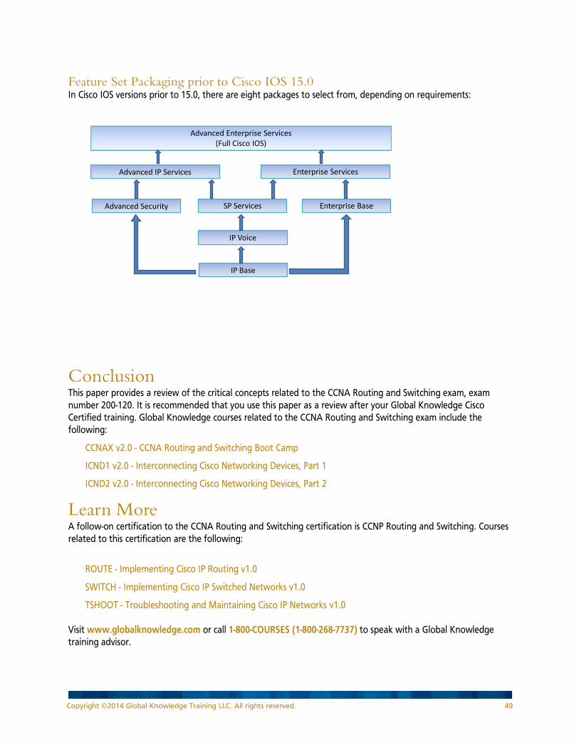
Feature Set Packaging prior to Cisco IOS 15.0 In Cisco IOS versions prior to 15.0, there are eight packages to select from, depending on requirements:
Advanced Enterprise Services(Full Cisco IOS)
Advanced IP Services Enterprise Services
Advanced Security Enterprise BaseSP Services
IP Voice
IP Base
Conclusion This paper provides a review of the critical concepts related to the CCNA Routing and Switching exam, exam number 200-120. It is recommended that you use this paper as a review after your Global Knowledge Cisco Certified training. Global Knowledge courses related to the CCNA Routing and Switching exam include the following:
CCNAX v2.0 - CCNA Routing and Switching Boot Camp
ICND1 v2.0 - Interconnecting Cisco Networking Devices, Part 1
ICND2 v2.0 - Interconnecting Cisco Networking Devices, Part 2
Learn More A follow-on certification to the CCNA Routing and Switching certification is CCNP Routing and Switching. Courses related to this certification are the following:
ROUTE - Implementing Cisco IP Routing v1.0
SWITCH - Implementing Cisco IP Switched Networks v1.0
TSHOOT - Troubleshooting and Maintaining Cisco IP Networks v1.0 Visit www.globalknowledge.com or call 1-800-COURSES (1-800-268-7737) to speak with a Global Knowledge training advisor.
Copyright ©2014 Global Knowledge Training LLC. All rights reserved. 49
About the Author Diane Teare is a professional in the networking, training, project management, and eLearning fields. She has more than 25 years of experience in designing, implementing, and troubleshooting network hardware and software, and has been involved in teaching, course design, and project management. Diane is the Course Director for CCNA and CCNP Routing and Switching courses with Global Knowledge, and teaches these and other Cisco and Project Management courses. She was the director of eLearning for Global Knowledge Canada, responsible for planning and supporting all the company’s eLearning offerings in Canada, including Cisco courses. Diane is a professional engineer, and has a bachelor's degree in applied science in electrical engineering and a master's degree in applied science in management science. She currently holds her Cisco Certified Network Professional (CCNP), Cisco Certified Design Professional (CCDP), and Project Management Professional (PMP) certifications, and is a Cisco Certified Systems Instructor (CCSI). She authored or co-authored 10 Cisco Press titles; the latest of these is Implementing Cisco IP Routing (ROUTE) Foundation Learning Guide.
Copyright ©2014 Global Knowledge Training LLC. All rights reserved. 50