route aggregation - david billings home · figure 18: vlsm permits route aggregation - reducing...
TRANSCRIPT

host-numberbits
130.5.0.0/26 = 10000010.00000101.00000000.00000000
network-prefix
extended-network-prefix
subnet-numberbits
Figure 16: 130.5.0.0/16 with a /26 Extended-Network Prefix
Route AggregationVLSM also allows the recursive division of an organization's address space so that it canbe reassembled and aggregated to reduce the amount of routing information at the toplevel. Conceptually, a network is first divided into subnets, some of the subnets arefurther divided into sub-subnets, and some of the sub-subnets are divided into sub2-subnets. This allows the detailed structure of routing information for one subnet groupto be hidden from routers in another subnet group.
11.0.0.0./8
11.1.0.0/16
11.2.0.0/16
11.3.0.0/16
11.252.0.0/16
11.253.0.0/16
11.254.0.0/16
11.1.1.0/24
11.1.2.0/24
11.1.253.0/24
11.1.254.0/24
11.253.32.0/19
11.253.64.0/19
11.253.160.0/19
11.253.192.0/19
11.1.253.32/27
11.1.253.64/27
11.1.253.160/27
11.1.253.192/27
Figure 17: VLSM Permits the Recursive Division of a Network Prefix
In Figure 17, the 11.0.0.0/8 network is first configured with a /16 extended-network-prefix. The 11.1.0.0/16 subnet is then configured with a /24 extended-network-prefixand the 11.253.0.0/16 subnet is configured with a /19 extended-network-prefix. Notethat the recursive process does not require that the same extended-network-prefix beassigned at each level of the recursion. Also, the recursive sub-division of theorganization's address space can be carried out as far as the network administrator needsto take it.

11.0.0.0/8or 11/8
11.2.0.0/16
11.3.0.0/16
11.252.0.0/16
11.254.0.0/16
11.1.0.0/1611.1.1.0/24
11.1.2.0/24
11.1.252.0/24
11.1.254.0/24
11.1.253.32/2711.1.253.64/27
11.1.253.160/2711.1.253.192/27
11.1.253.0/2411.253.0.0/16
11.253.32.0/19
11.253.64.0/19
11.253.160.0/19
11.253.192.0/19
Internet
Router A Router B
Router C Router D
11.1.253.96/2711.1.253.128/27
Figure 18: VLSM Permits Route Aggregation - Reducing Routing Table Size
Figure 18 illustrates how a planned and thoughtful allocation of VLSM can reduce thesize of an organization's routing tables. Notice how Router D is able to summarize thesix subnets behind it into a single advertisement (11.1.253.0/24) and how Router B isable to aggregate all of subnets behind it into a single advertisement. Likewise, Router Cis able to summarize the six subnets behind it into a single advertisement(11.253.0.0/16). Finally, since the subnet structure is not visible outside of theorganization, Router A injects a single route into the global Internet's routing table -11.0.0.0/8 (or 11/8).
VLSM Design ConsiderationsWhen developing a VLSM design, the network designer must recursively ask the sameset of questions as for a traditional subnet design. The same set of design decisionsmust be made at each level of the hierarchy:
1) How many total subnets does this level need today?
2) How many total subnets will this level need in the future?
3) How many hosts are there on this level's largest subnet today?
4) How many hosts will there be on this level's largest subnet be in the future?
At each level, the design team must make sure that they have enough extra bits tosupport the required number of sub-entities in the next and further levels of recursion.

Assume that a network is spread out over a number of sites. For example, if anorganization has three campuses today it probably needs 3-bits of subnetting (23 = 8) toallow the addition of more campuses in the future. Now, within each campus, there islikely to be a secondary level of subnetting to identify each building. Finally, withineach building, a third level of subnetting might identify each of the individualworkgroups. Following this hierarchical model, the top level is determined by thenumber of campuses, the mid-level is based on the number of buildings at each site, andthe lowest level is determined by the "maximum number of subnets/maximum numberof users per subnet" in each building.
The deployment of a hierarchical subnetting scheme requires careful planning. It isessential that the network designers recursively work their way down through theiraddressing plan until they get to the bottom level. At the bottom level, they must makesure that the leaf subnets are large enough to support the required number of hosts.When the addressing plan is deployed, the addresses from each site will be aggregableinto a single address block that keeps the backbone routing tables from becoming toolarge.
Requirements for the Deployment of VLSMThe successful deployment of VLSM has three prerequisites:
- The routing protocols must carry extended-network-prefix information with eachroute advertisement.
- All routers must implement a consistent forwarding algorithm based on the "longestmatch."
- For route aggregation to occur, addresses must be assigned so that they havetopological significance.
Routing Protocols Must Carry Extended-Network-Prefix Lengths
Modern routing protocols, such as OSPF and I-IS-IS, enable the deployment of VLSMby providing the extended-network-prefix length or mask value along with each routeadvertisement. This permits each subnetwork to be advertised with its correspondingprefix length or mask. If the routing protocols did not carry prefix information, a routerwould have to either assume that the locally configured prefix length should be applied,or perform a look-up in a statically configured prefix table that contains all of therequired masking information. The first alternative cannot guarantee that the correctprefix is applied, and static tables do not scale since they are difficult to maintain andsubject to human error.
The bottom line is that if you want to deploy VLSM in a complex topology, you mustselect OSPF or I-IS-IS as the Interior Gateway Protocol (IGP) rather than RIP-1! Itshould be mentioned that RIP-2, defined in RFC 1388, improves the RIP protocol byallowing it to carry extended-network-prefix information. Therefore, RIP-2 supports thedeployment of VLSM.

Forwarding Algorithm is Based on the "Longest Match"
All routers must implement a consistent forwarding algorithm based on the "longestmatch" algorithm. The deployment of VLSM means that the set of networks associatedwith extended-network-prefixes may manifest a subset relationship. A route with alonger extended-network-prefix describes a smaller set of destinations than the sameroute with a shorter extended-network-prefix. As a result, a route with a longerextended-network-prefix is said to be "more specific" while a route with a shorterextended-network-prefix is said to be "less specific." Routers must use the route withthe longest matching extended-network-prefix (most specific matching route) whenforwarding traffic.
For example, if a packet's destination IP address is 11.1.2.5 and there are three networkprefixes in the routing table (11.1.2.0/24, 11.1.0.0/16, and 11.0.0.0/8), the router wouldselect the route to 11.1.2.0/24. The 11.1.2.0/24 route is selected because its prefix hasthe greatest number of corresponding bits in the Destination IP address of the packet.This is illustrated in Figure 19.
Destination 11.1.2.5 = 00001011.00000001.00000010.00000101
Route #3 11.0.0.0/8 = 00001011.00000000.00000000.00000000
Route #2 11.1.0.0/16 = 00001011.00000001.00000000.00000000
Route #1 11.1.2.0/24 = 00001011.00000001.00000010.00000000*
Figure 19: Best Match is with the Route Having the Longest Prefix (Most Specific)
There is a very subtle but extremely important issue here. Since the destination addressmatches all three routes, it must be assigned to a host which is attached to the11.1.2.0/24 subnet. If the 11.1.2.5 address is assigned to a host that is attached to the11.1.0.0/16 or 11.0.0.0/8 subnet, the routing system will never route traffic to the hostsince the "longest match algorithm" assumes that the host is part of the 11.1.2.0/24subnet. This means that great care must be taken when assigning host addresses tomake sure that every host is reachable!
Topologically Significant Address Assignment
Since OSPF and I-IS-IS convey the extended-network-prefix information with eachroute, the VLSM subnets can be scattered throughout an organization's topology.However, to support hierarchical routing and reduce the size of an organization's routingtables, addresses should be assigned so that they are topologically significant.
Hierarchical routing requires that addresses be assigned to reflect the actual networktopology. This reduces the amount of routing information by taking the set of addressesassigned to a particular region of the topology, and aggregating them into a singlerouting advertisement for the entire set. Hierarchical routing allows this to be donerecursively at various points within the hierarchy of the routing topology. If addressesdo not have a topological significance, aggregation cannot be performed and the size ofthe routing tables cannot be reduced. Remember this point when we discuss CIDRaggregation later in this paper.

VLSM ExampleGiven
An organization has been assigned the network number 140.25.0.0/16 and it plans todeploy VLSM. Figure 20 provides a graphic display of the VLSM design for theorganization.
140.25.0.0/16
0 1 2 3 12 13 14 15
0 1 30 31 0 1 14 15
0 1 6 7
Figure 20: Address Strategy for VLSM Example
The first step of the subnetting process divides the base network address into 16 equal-sized address blocks. Then Subnet #1 is divided it into 32 equal-sized address blocksand Subnet #14 is divided into 16 equal-sized address blocks. Finally, Subnet #14-14 isdivided into 8 equal-sized address blocks.
Define the 16 Subnets of 140.25.0.0/16
The first step in the subnetting process divides the base network address into 16 equal-size address blocks. This is illustrated in Figure 21.
140.25.0.0/16
0 1 2 3 12 13 14 15
0 1 30 31 0 1 14 15
0 1 6 7
Figure 21: Define the 16 Subnets for 140.25.0.0/16
Since 16 = 24, four bits are required to uniquely identify each of the 16 subnets. Thismeans that the organization needs four more bits, or a /20, in the extended-network-prefix to define the 16 subnets of 140.25.0.0/16. Each of these subnets represents acontiguous block of 212 (or 4,096) network addresses.

The 16 subnets of the 140.25.0.0/16 address block are given below. The subnets arenumbered 0 through 15. The underlined portion of each address identifies the extended-network-prefix, while the bold digits identify the 4-bits representing the subnet-numberfield:
Base Network: 10001100.00011001 .00000000.00000000 = 140.25.0.0/16
Subnet #0: 10001100.00011001. 0000 0000.00000000 = 140.25.0.0/20Subnet #1: 10001100.00011001. 0001 0000.00000000 = 140.25.16.0/20Subnet #2: 10001100.00011001. 0010 0000.00000000 = 140.25.32.0/20Subnet #3: 10001100.00011001. 0011 0000.00000000 = 140.25.48.0/20Subnet #4: 10001100.00011001. 0100 0000.00000000 = 140.25.64.0/20
::
Subnet #13: 10001100.00011001. 1101 0000.00000000 = 140.25.208.0/20Subnet #14: 10001100.00011001. 1110 0000.00000000 = 140.25.224.0/20Subnet #15: 10001100.00011001. 1111 0000.00000000 = 140.25.240.0/20
Define the Host Addresses for Subnet #3 (140.25.48.0/20)
Let's examine the host addresses that can be assigned to Subnet #3 (140.25.48.0/20).This is illustrated in Figure 22.
140.25.0.0/16
0 1 2 3 12 13 14 15
0 1 30 31 0 1 14 15
0 1 6 7
Figure 22: Define the Host Addresses for Subnet #3 (140.25.48.0/20)
Since the host-number field of Subnet #3 contains 12 bits, there are 4,094 valid hostaddresses (212-2) in the address block. The hosts are numbered 1 through 4,094.
The valid host addresses for Subnet #3 are given below. The underlined portion of eachaddress identifies the extended-network-prefix, while the bold digits identify the 12-bithost-number field:
Subnet #3: 10001100.00011001.0011 0000.00000000 = 140.25.48.0/20
Host #1: 10001100.00011001.0011 0000.00000001 = 140.25.48.1/20Host #2: 10001100.00011001.0011 0000.00000010 = 140.25.48.2/20Host #3: 10001100.00011001.0011 0000.00000011 = 140.25.48.3/20
::
Host #4093: 10001100.00011001.0011 1111.11111101 = 140.25.63.253/20Host #4094: 10001100.00011001.0011 1111.11111110 = 140.25.63.254/20

The broadcast address for Subnet #3 is the all 1's host address or:
10001100.00011001.0011 1111.11111111 = 140.25.63.255
The broadcast address for Subnet #3 is exactly one less than the base address for Subnet#4 (140.25.64.0).
Define the Sub-Subnets for Subnet #14 (140.25.224.0/20)
After the base network address is divided into sixteen subnets, Subnet #14 is furthersubdivided into 16 equal-size address blocks. This is illustrated in Figure 23.
140.25.0.0/16
0 1 2 3 12 13 14 15
0 1 30 31 0 1 14 15
0 1 6 7
Figure 23: Define the Sub-Subnets for Subnet #14 (140.25.224.0/20)
Since 16 = 24, four more bits are required to identify each of the 16 subnets. Thismeans that the organization will need to use a /24 as the extended-network-prefix length.
The 16 subnets of the 140.25.224.0/20 address block are given below. The subnets arenumbered 0 through 15. The underlined portion of each sub-subnet address identifiesthe extended-network-prefix, while the bold digits identify the 4-bits representing thesub-subnet-number field:
Subnet #14: 10001100.00011001.1110 0000.00000000 = 140.25.224.0/20
Subnet #14-0: 10001100.00011001.1110 0000 .00000000 = 140.25.224.0/24Subnet #14-1: 10001100.00011001.1110 0001 .00000000 = 140.25.225.0/24Subnet #14-2: 10001100.00011001.1110 0010 .00000000 = 140.25.226.0/24Subnet #14-3: 10001100.00011001.1110 0011 .00000000 = 140.25.227.0/24Subnet #14-4: 10001100.00011001.1110 0100 .00000000 = 140.25.228.0/24
::
Subnet #14-14: 10001100.00011001.1110 1110 .00000000 = 140.25.238.0/24Subnet #14-15: 10001100.00011001.1110 1111 .00000000 = 140.25.239.0/24

Define Host Addresses for Subnet #14-3 (140.25.227.0/24)
Let's examine the host addresses that can be assigned to Subnet #14-3(140.25.227.0/24). This is illustrated in Figure 24.
140.25.0.0/16
0 1 2 3 12 13 14 15
0 1 30 31 0 1 14 15
0 1 6 7
3
Figure 24: Define the Host Addresses for Subnet #14-3 (140.25.227.0/24)
Each of the subnets of Subnet #14-3 has 8 bits in the host-number field. This meansthat each subnet represents a block of 254 valid host addresses (28-2). The hosts arenumbered 1 through 254.
The valid host addresses for Subnet #14-3 are given below. The underlined portion ofeach address identifies the extended-network-prefix, while the bold digits identify the 8-bit host-number field:
Subnet #14-3: 10001100.00011001.11100011 .00000000 = 140.25.227.0/24
Host #1 10001100.00011001.11100011 .00000001 = 140.25.227.1/24Host #2 10001100.00011001.11100011 .00000010 = 140.25.227.2/24Host #3 10001100.00011001.11100011 .00000011 = 140.25.227.3/24Host #4 10001100.00011001.11100011 .00000100 = 140.25.227.4/24Host #5 10001100.00011001.11100011 .00000101 = 140.25.227.5/24
.
.Host #253 10001100.00011001.11100011 .11111101 = 140.25.227.253/24Host #254 10001100.00011001.11100011 .11111110 = 140.25.227.254/24
The broadcast address for Subnet #14-3 is the all 1's host address or:
10001100.00011001.11100011 .11111111 = 140.25.227.255
The broadcast address for Subnet #14-3 is exactly one less than the base address forSubnet #14-4 (140.25.228.0).

Define the Sub2-Subnets for Subnet #14-14 (140.25.238.0/24)
After Subnet #14 was divided into sixteen subnets, Subnet #14-14 is further subdividedinto 8 equal-size address blocks. This is illustrated in Figure 25.
140.25.0.0/16
0 1 2 3 12 13 14 15
0 1 30 31 0 1 14 15
0 1 6 7
Figure 25: Define the Sub2-Subnets for Subnet #14-14 (140.25.238.0/24)
Since 8 = 23, three more bits are required to identify each of the 8 subnets. This meansthat the organization will need to use a /27 as the extended-network-prefix length.
The 8 subnets of the 140.25.238.0/24 address block are given below. The subnets arenumbered 0 through 7. The underlined portion of each sub-subnet address identifies theextended-network-prefix, while the bold digits identify the 3-bits representing thesubnet2-number field:
Subnet #14-14: 10001100.00011001.11101110 .00000000 = 140.25.238.0/24
Subnet#14-14-0: 10001100.00011001.11101110. 000 00000 = 140.25.238.0/27Subnet#14-14-1: 10001100.00011001.11101110. 001 00000 = 140.25.238.32/27Subnet#14-14-2: 10001100.00011001.11101110. 010 00000 = 140.25.238.64/27Subnet#14-14-3: 10001100.00011001.11101110. 011 00000 = 140.25.238.96/27Subnet#14-14-4: 10001100.00011001.11101110. 100 00000 = 140.25.238.128/27Subnet#14-14-5: 10001100.00011001.11101110. 101 00000 = 140.25.238.160/27Subnet#14-14-6: 10001100.00011001.11101110. 110 00000 = 140.25.238.192/27Subnet#14-14-7: 10001100.00011001.11101110. 111 00000 = 140.25.238.224/27

Define Host Addresses for Subnet #14-14-2 (140.25.238.64/27)
Let's examine the host addresses that can be assigned to Subnet #14-14-2(140.25.238.64/27). This is illustrated in Figure 26.
140.25.0.0/16
0 1 2 3 12 13 14 15
0 1 30 31 0 1 14 15
0 1 6 72
Figure 26: Define the Host Addresses for Subnet #14-14-2 (140.25.238.64/27)
Each of the subnets of Subnet #14-14 has 5 bits in the host-number field. This meansthat each subnet represents a block of 30 valid host addresses (25-2). The hosts will benumbered 1 through 30.
The valid host addresses for Subnet #14-14-2 are given below. The underlined portionof each address identifies the extended-network-prefix, while the bold digits identify the5-bit host-number field:
Subnet#14-14-2: 10001100.00011001.11101110.010 00000 = 140.25.238.64/27
Host #1 10001100.00011001.11101110.010 00001 = 140.25.238.65/27Host #2 10001100.00011001.11101110.010 00010 = 140.25.238.66/27Host #3 10001100.00011001.11101110.010 00011 = 140.25.238.67/27Host #4 10001100.00011001.11101110.010 00100 = 140.25.238.68/27Host #5 10001100.00011001.11101110.010 00101 = 140.25.238.69/27
.
.Host #29 10001100.00011001.11101110.010 11101 = 140.25.238.93/27Host #30 10001100.00011001.11101110.010 11110 = 140.25.238.94/27
The broadcast address for Subnet #14-14-2 is the all 1's host address or:
10001100.00011001.11011100.010 11111 = 140.25.238.95
The broadcast address for Subnet #6-14-2 is exactly one less than the base address forSubnet #14-14-3 (140.25.238.96).
Additional Practice with VLSMPlease turn to Appendix D for practice exerciss to reinforce your understanding ofVLSM.
Classless Inter-Domain Routing (CIDR)By 1992, the exponential growth of the Internet was beginning to raise serious concernsamong members of the IETF about the ability of the Internet's routing system to scaleand support future growth. These problems were related to:
- The near-term exhaustion of the Class B network address space- The rapid growth in the size of the global Internet's routing tables- The eventual exhaustion of the 32-bit IPv4 address space
Projected Internet growth figures made it clear that the first two problems were likely tobecome critical by 1994 or 1995. The response to these immediate challenges was thedevelopment of the concept of Supernetting or Classless Inter-Domain Routing (CIDR).The third problem, which is of a more long-term nature, is currently being explored bythe IP Next Generation (IPng or IPv6) working group of the IETF.
CIDR was officially documented in September 1993 in RFC 1517, 1518, 1519, and1520. CIDR supports two important features that benefit the global Internet routingsystem:
- CIDR eliminates the traditional concept of Class A, Class B, and Class C networkaddresses. This enables the efficient allocation of the IPv4 address space which willallow the continued growth of the Internet until IPv6 is deployed.
- CIDR supports route aggregation where a single routing table entry can represent theaddress space of perhaps thousands of traditional classful routes. This allows asingle routing table entry to specify how to route traffic to many individual networkaddresses. Route aggregation helps control the amount of routing information in theInternet's backbone routers, reduces route flapping (rapid changes in routeavailability), and eases the local administrative burden of updating external routinginformation.
Without the rapid deployment of CIDR in 1994 and 1995, the Internet routing tableswould have in excess of 70,000 routes (instead of the current 30,000+) and the Internetwould probably not be functioning today!
CIDR Promotes the Efficient Allocation of the IPv4 Address SpaceCIDR eliminates the traditional concept of Class A, Class B, and Class C networkaddresses and replaces them with the generalized concept of a "network-prefix."Routers use the network-prefix, rather than the first 3 bits of the IP address, to determinethe dividing point between the network number and the host number. As a result, CIDRsupports the deployment of arbitrarily sized networks rather than the standard 8-bit, 16-bit, or 24-bit network numbers associated with classful addressing.
In the CIDR model, each piece of routing information is advertised with a bit mask (orprefix-length). The prefix-length is a way of specifying the number of leftmostcontiguous bits in the network-portion of each routing table entry. For example, a
network with 20 bits of network-number and 12-bits of host-number would beadvertised with a 20-bit prefix length (a /20). The clever thing is that the IP addressadvertised with the /20 prefix could be a former Class A, Class B, or Class C. Routersthat support CIDR do not make assumptions based on the first 3-bits of the address,they rely on the prefix-length information provided with the route.
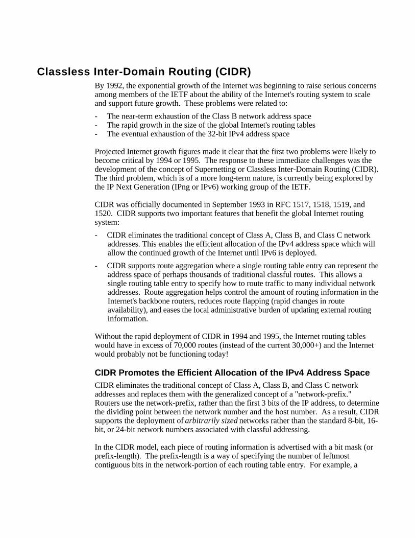
In a classless environment, prefixes are viewed as bitwise contiguous blocks of the IPaddress space. For example, all prefixes with a /20 prefix represent the same amount ofaddress space (212 or 4,096 host addresses). Furthermore, a /20 prefix can be assignedto a traditional Class A, Class B, or Class C network number. Figure 27 shows howeach of the following /20 blocks represent 4,096 host addresses - 10.23.64.0/20,130.5.0.0/20, and 200.7.128.0/20.
10.23.64.0/20
130.5.0.0/20
200.7.128.0/20
00001010.00010111.01000000.00000000
10000010.00000101.00000000.00000000
11001000.00000111.10000000.00000000
Traditional A
Traditional B
Traditional C
Figure 27: /20 Bitwise Contiguous Address Blocks
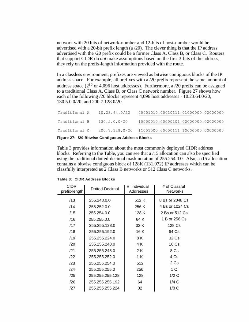
Table 3 provides information about the most commonly deployed CIDR addressblocks. Referring to the Table, you can see that a /15 allocation can also be specifiedusing the traditional dotted-decimal mask notation of 255.254.0.0. Also, a /15 allocationcontains a bitwise contiguous block of 128K (131,072) IP addresses which can beclassfully interpreted as 2 Class B networks or 512 Class C networks.
Table 3: CIDR Address Blocks
CIDR prefix-length
Dotted-Decimal# Individual Addresses
# of Classful Networks
/13
/14
/15
/16
/17
/18
/19
/20
/21
/22
/23
/24
/25
/26
/27
255.248.0.0
255.252.0.0
255.254.0.0
255.255.0.0
255.255.128.0
255.255.192.0
255.255.224.0
255.255.240.0
255.255.248.0
255.255.252.0
255.255.254.0
255.255.255.0
255.255.255.128
255.255.255.192
255.255.255.224
512 K
256 K
128 K
64 K
32 K
16 K
8 K
4 K
2 K
1 K
512
256
64
32
8 Bs or 2048 Cs
4 Bs or 1024 Cs
2 Bs or 512 Cs
1 B or 256 Cs
128 Cs
64 Cs
32 Cs
16 Cs
8 Cs
4 Cs
2 Cs
1 C
1/2 C
1/4 C
1/8 C
128

Host Implications for CIDR Deployment
It is important to note that there may be severe host implications when you deployCIDR based networks. Since many hosts are classful, their user interface will notpermit them to be configured with a mask that is shorter than the "natural" mask for atraditional classful address. For example, potential problems could exist if you wantedto deploy 200.25.16.0 as a /20 to define a network capable of supporting 4,094 (212-2)hosts. The software executing on each end station might not allow a traditional Class C(200.25.16.0) to be configured with a 20-bit mask since the natural mask for a Class Cnetwork is a 24-bit mask. If the host software supports CIDR, it will permit shortermasks to be configured.
However, there will be no host problems if you were to deploy the 200.25.16.0/20 (atraditional Class C) allocation as a block of 16 /24s since non-CIDR hosts will interprettheir local /24 as a Class C. Likewise, 130.14.0.0/16 (a traditional Class B) could bedeployed as a block of 255 /24s since the hosts will interpret the /24s as subnets of a /16.If host software supports the configuration of shorter than expected masks, the networkmanager has tremendous flexibility in network design and address allocation.
Efficient Address Allocation
How does all of this lead to the efficient allocation of the IPv4 address space? In aclassful environment, an Internet Service Provider (ISP) can only allocate /8, /16, or /24addresses. In a CIDR environment, the ISP can carve out a block of its registeredaddress space that specifically meets the needs of each client, provides additional roomfor growth, and does not waste a scarce resource.
Assume that an ISP has been assigned the address block 206.0.64.0/18. This blockrepresents 16,384 (214) IP addresses which can be interpreted as 64 /24s. If a clientrequires 800 host addresses, rather than assigning a Class B (and wasting ~64,700addresses) or four individual Class Cs (and introducing 4 new routes into the globalInternet routing tables), the ISP could assign the client the address block 206.0.68.0/22,a block of 1,024 (210) IP addresses (4 contiguous /24s). The efficiency of this allocationis illustrated in Figure 28.
ISP's Block:
Client Block:
206.0.64.0/1811001110.00000000.01000000.00000000
206.0.68.0/2211001110.00000000.01000100.00000000
Class C #0:
Class C #1:
Class C #2:
Class C #3:
206.0.68.0/24
206.0.69.0/24
206.0.70.0/24
206.0.71.0/24
11001110.00000000.01000100.00000000
11001110.00000000.01000101.00000000
11001110.00000000.01000110.00000000
11001110.00000000.01000111.00000000
Figure 28: CIDR Supports Efficient Address Allocation

CIDR Address Allocation Example
For this example, assume that an ISP owns the address block 200.25.0.0/16. This blockrepresents 65, 536 (216) IP addresses (or 256 /24s).
From the 200.25.0.0/16 block it wants to allocate the 200.25.16.0/20 address block .This smaller block represents 4,096 (212) IP addresses (or 16 /24s).
Address Block 11001000.00011001.0001 0000.00000000 200.25.16.0/20
In a classful environment, the ISP is forced to use the /20 as 16 individual /24s.
Network #0 11001000.00011001.0001 0000 .00000000 200.25.16.0/24Network #1 11001000.00011001.0001 0001 .00000000 200.25.17.0/24Network #2 11001000.00011001.0001 0010 .00000000 200.25.18.0/24Network #3 11001000.00011001.0001 0011 .00000000 200.25.19.0/24Network #4 11001000.00011001.0001 0100 .00000000 200.25.20.0/24
::
Network #13 11001000.00011001.0001 1101 .00000000 200.25.29.0/24Network #14 11001000.00011001.0001 1110 .00000000 200.25.30.0/24Network #15 11001000.00011001.0001 1111 .00000000 200.25.31.0/24
If you look at the ISP's /20 address block as a pie, in a classful environment it can onlybe cut into 16 equal-size pieces. This is illustrated in Figure 29.
200.25.16.0/24
200.25.17.0/24
200.25.18.0/24
200.25.19.0/24
200.25.20.0/24
200.25.21.0/24
200.25.22.0/24
200.25.23.0/24
200.25.31.0/24
200.25.30.0/24
200.25.29.0/24
200.25.28.0/24
200.25.27.0/24
200.25.26.0/24
200.25.25.0/24
200.25.24.0/24
1413
12
11
109
76
5
4
3
21
0
8
15
Figure 29: Slicing the Pie - Classful Environment
However, in a classless environment, the ISP is free to cut up the pie any way it wants.It could slice up the original pie into 2 pieces (each 1/2 of the address space) and assignone portion to Organization A, then cut the other half into 2 pieces (each 1/4 of theaddress space) and assign one piece to Organization B, and finally slice the remainingfourth into 2 pieces (each 1/8 of the address space) and assign it to Organization C andOrganization D. Each of the individual organizations is free to allocate the address spacewithin its "Intranetwork" as it sees fit. This is illustrated in Figure 30.

200.25.24.0/22
200.25.28.0/23
200.25.30.0/23
200.25.16.0/21A
B
C
D
Figure 30: Slicing the Pie - Classless Environment
Step #1: Divide the address block 200.25.16.0/20 into two equal size slices. Each blockrepresents one-half of the address space or 2,048 (211) IP addresses.
ISP's Block 11001000.00011001.0001 0000.00000000 200.25.16.0/20
Org A: 11001000.00011001.0001 0 000.00000000 200.25.16.0/21Reserved: 11001000.00011001.0001 1 000.00000000 200.25.24.0/21
Step #2: Divide the reserved block (200.25.24.0/21) into two equal size slices. Eachblock represents one-fourth of the address space or 1,024 (210) IP addresses.
Reserved 11001000.00011001.00011 000.00000000 200.25.24.0/21
Org B: 11001000.00011001.00011 0 00.00000000 200.25.24.0/22Reserved 11001000.00011001.00011 1 00.00000000 200.25.28.0/22
Step #3: Divide the reserved address block (200.25.28.0/22) into two equal size blocks.Each block represents one-eight of the address space or 512 (29) IP addresses.
Reserved 11001000.00011001.000111 00.00000000 200.25.28.0/22
Org C: 11001000.00011001.000111 0 0.00000000 200.25.28.0/23Org D: 11001000.00011001.000111 1 0.00000000 200.25.30.0/23
CIDR is Similar to VLSM
If CIDR appears to have the familiar look and feel of VLSM, you're correct! CIDR andVLSM are essentially the same thing since they both allow a portion of the IP addressspace to be recursively divided into subsequently smaller pieces. The difference is thatwith VLSM, the recursion is performed on the address space previously assigned to anorganization and is invisible to the global Internet. CIDR, on the other hand, permits therecursive allocation of an address block by an Internet Registry to a high-level ISP, to amid-level ISP, to a low-level ISP, and finally to a private organization's network.

Just like VLSM, the successful deployment of CIDR has three prerequisites:
- The routing protocols must carry network-prefix information with each routeadvertisement.
- All routers must implement a consistent forwarding algorithm based on the "longestmatch."
- For route aggregation to occur, addresses must be assigned so that they aretopologically significant.
Controlling the Growth of Internet's Routing TablesAnother important benefit of CIDR is that it plays an important role in controlling thegrowth of the Internet's routing tables. The reduction of routing information requiresthat the Internet be divided into addressing domains. Within a domain, detailedinformation is available about all of the networks that reside in the domain. Outside ofan addressing domain, only the common network prefix is advertised. This allows asingle routing table entry to specify a route to many individual network addresses.
200.25.0.0./16The Internet
Organization A
Organization D
Organization B
Organization C
200.25.16.0/20
200.25.16.0/21 200.25.24.0/22 200.25.28.0/23 200.25.30.0/23
200.25.28.0/24200.25.29.0/24
200.25.30.0/24200.25.31.0/24
200.25.24.0/24200.25.25.0/24200.25.26.0/24200.25.27.0/24
200.25.16.0/24200.25.17.0/24200.25.18.0/24200.25.19.0/24200.25.20.0/24200.25.21.0/24200.25.22.0/24220.25.23.0/24
Internet ServiceProvider
Figure 31: CIDR Reduces the Size of Internet Routing Tables
Figure 31 illustrates how the allocation described in previous CIDR example helpsreduce the size of the Internet routing tables. Assume that a portion of the ISPs addressblock (200.25.16.0/20) has been allocated as described in the previous example.Organization A aggregates 8 /24s into a single advertisement (200.25.16.0/21),Organization B aggregates 4 /24s into a single advertisement (200.25.24.0/22),Organization C aggregates 2 /24s into a single advertisement (200.25.28.0/23), and
Organization D aggregates 2 /24s into a single advertisement (200.25.30.0/23). Finally,the ISP is able to inject the 256 /24s in its allocation into the Internet with a singleadvertisement - 200.25.0.0/16!
It should be mentioned that route aggregation via BGP-4 is not automatic. The networkengineers must configure each router to perform the required aggregation. Thesuccessful deployment of CIDR will allow the number of individual networks on theInternet to expand, while minimizing the number of routes in the Internet routing tables.
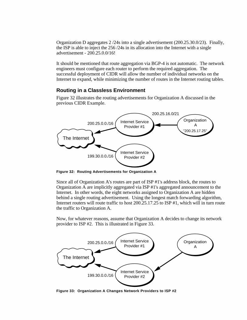
Routing in a Classless EnvironmentFigure 32 illustrates the routing advertisements for Organization A discussed in theprevious CIDR Example.
200.25.0.0./16
The Internet
Internet ServiceProvider #1
199.30.0.0./16
200.25.16.0/21
Internet ServiceProvider #2
Organization A
"200.25.17.25"
Figure 32: Routing Advertisements for Organization A
Since all of Organization A's routes are part of ISP #1's address block, the routes toOrganization A are implicitly aggregated via ISP #1's aggregated announcement to theInternet. In other words, the eight networks assigned to Organization A are hiddenbehind a single routing advertisement. Using the longest match forwarding algorithm,Internet routers will route traffic to host 200.25.17.25 to ISP #1, which will in turn routethe traffic to Organization A.
Now, for whatever reasons, assume that Organization A decides to change its networkprovider to ISP #2. This is illustrated in Figure 33.
200.25.0.0./16
The Internet
Internet ServiceProvider #1
199.30.0.0./16Internet Service
Provider #2
Organization A
Figure 33: Organization A Changes Network Providers to ISP #2

The "best" thing for the size of the Internet's routing tables would be to haveOrganization A obtain a block of ISP #2's address space and renumber. This wouldallow the eight networks assigned to Organization A to be hidden behind the aggregaterouting advertisement of ISP #2. Unfortunately, renumbering is a labor-intensive taskwhich could be very difficult, if not impossible, for Organization A.
199.30.0.0./16
200.25.0.0./16
The Internet
Internet ServiceProvider #1
Internet ServiceProvider #2
200.25.16.0/21
200.25.16.0/21
Organization A
"200.25.17.25"
Figure 34: ISP #2 Injects a More-Specific Route into the Internet
The "best" thing for Organization A is to retain ownership of its address space and haveISP #2 advertise an "exception" (more specific) route into the Internet. The exceptionroute allows all traffic for 200.25.0.0/16 to be sent to ISP #1, with the exception of thetraffic to 200.25.16.0/21. This is accomplished by having ISP #2 advertise, in additionto its own 199.30.0.0/16 block, a route for 200.25.16.0/21. Please refer to Figure 34.Using the "longest match" forwarding algorithm, Internet routers will route trafficaddressed to host 200.25.17.25 to ISP #2 which will in turn route the traffic toOrganization A. Clearly, the introduction of a large number of exception routes canreduce the effectiveness of the CIDR deployment and eventually cause Internet routingtables to begin exploding again!
NETBuilder Support for CIDRSupport for CIDR has been implemented on the NETBuilder:
- NETBuilder software implements BGP-4. Support for CIDR is a significant part ofthe improvements made to BGP-4.
- NETBuilder software uses a routing table structure that understands a networknumber advertised with a prefix that is shorter than the natural mask. TheNETBuilder's routing table and forwarding process ignore the traditional IP addressClass and are capable of accepting any network/mask combination that it receives.
- NETBuilder software is capable of performing aggregation by way of BGP-4configuration parameters. Also, the OSPF AreaRange parameter allows VLSM-based aggregation to be performed within an autonomous system. The networkadministrator may specify exactly what network numbers and masks are advertisedoutside of each area or domain.

Additional Practice with CIDRPlease turn to Appendix E for several practice exercises to reinforce your understandingof CIDR.
New Solutions for Scaling the Internet Address SpaceAs we approach the turn of the century, the problems of IPv4 address shortages andexpanding Internet routing tables are still with us. The good news is that CIDR isworking. The bad news is that recent growth trends indicate that the number of Internetroutes is beginning to, once again, increase at an exponential rate. The Internet must finda way to keep the routing table growth linear. The IETF is continuing its efforts todevelop solutions that will overcome these problems, enabling the continued growth andscalability of the Internet.
Appeal to Return Unused IP Network PrefixesRFC 1917 requests that the Internet community return unused address blocks to theInternet Assigned Numbers Authority (IANA) for redistribution. This includes unusednetwork numbers, addresses for networks that will never be connected to the globalInternet for security reasons, and sites that are using a small percentage of their addressspace. RFC 1917 also petitions ISPs to return unused network-prefixes that are outsideof their assigned address blocks. It will be interesting to see how the Internetcommunity responds since many organizations with unused addresses don't want toreturn them because they are viewed as an asset.
Address Allocation for Private InternetsRFC 1918 requests that organizations make use of the private Internet address space forhosts that require IP connectivity within their enterprise network, but do not requireexternal connections to the global Internet. For this purpose, the IANA has reserved thefollowing three address blocks for private internets:
10.0.0.0 - 10.255.255.255 (10/8 prefix)172.16.0.0 - 172.31.255.255 (172.16/12 prefix)192.168.0.0 - 192.168.255.255 (192.168/16 prefix)
Any organization that elects to use addresses from these reserved blocks can do sowithout contacting the IANA or an Internet registry. Since these addresses are neverinjected into the global Internet routing system, the address space can simultaneously beused by many different organizations.
The disadvantage to this addressing scheme is that it requires an organization to use aNetwork Address Translator (NAT) for global Internet access. However, the use of theprivate address space and a NAT make it much easier for clients to change their ISPwithout the need to renumber or "punch holes" in a previously aggregatedadvertisement. The benefits of this addressing scheme to the Internet is that it reducesthe demand for IP addresses so large organizations may require only a small block ofthe globally unique IPv4 address space.

Address Allocation from the Reserved Class A Address SpaceAn Internet draft, "Observations on the use of Components of the Class A AddressSpace within the Internet" <draft-ietf-cidrd-classa-01.txt>, explores the allocation of theupper-half of the currently reserved Class A address space through delegated registries.As the demand for IP addresses continues to grow, it appears that it may be necessary toeventually allocate the 64.0.0.0/2 address space. Note that the 64.0.0.0/2 address blockis huge and represents 25% of the IPv4 unicast address space.
Implications of Address Allocation PoliciesAn Internet draft , "Implications of Various Address Allocation Policies for InternetRouting" <draft-ietf-cidrd-addr-ownership-07.txt>, discusses the fundamental issuesthat must be considered as the Internet develops a new unicast address allocation andmanagement policies. The draft compares the benefits and limitations of an "addressownership" policy with an "address lending" policy.
"Address ownership" means that when an address block is assigned to an organization,it remains allocated to that organization for as long as the organization wants to keep it.This means that the address block is "portable" and that the organization would be ableto use it to gain access to the Internet no matter where the organization connects to theInternet. On the other hand, "address lending" means that an organization obtains itsaddress block on a "loan" basis. If the loan ends, the organization can no longer use theborrowed address block, must obtain new addresses, and renumber before using them.
As we have seen, hierarchical routing requires that addresses reflect the networktopology in order to permit route aggregation. The draft argues that there are twofundamental problems that break the hierarchical addressing and routing modelsupported by CIDR:
- The continued existence of pre-CIDR routes that cannot be aggregated.
- Organizations that switch ISPs and continue to use addresses from their previousISP's address block. The new ISP cannot aggregate the old address block as part ofits aggregation, so it must inject an exception route into the Internet. If the numberof exception routes continues to increases, they will erode the benefits of CIDR andprevent the scalability of the Internet's routing system.
The draft concludes with the recommendation that large providers, which can expresstheir destinations with a single prefix, be assigned address blocks following the "addressownership" model. However, all allocations from these providers to a downstreamclients should follow the "address lending" model. This means that if an organizationchanges its provider, the loan is canceled and the client will be required to renumber.
This draft has generated a tremendous amount of discussion within the Internetcommunity about the concept of address ownership and what it means in the context ofglobal routing. The authors present a strong argument that the Internet has to make achoice between either address ownership for all or a routable Internet - it can't have

both! Smaller organizations that want to own their addresses have concerns about thedifficulty of renumbering and their lack of self-determination if their provider or theirprovider's upstream provider changes its provider. Finally, ISPs have concerns becausethe term "large provider" has not been defined. At this time, the discussion continuessince any criteria recommended by the IETF is bound to be perceived as unfair bysome!
Procedures for Internet/Enterprise Renumbering (PIER)In the face of the "address ownership" vs. "address lending" debate, it is clear thatrenumbering may become a critical issue in the late 1990s. Procedures forInternet/Enterprise Renumbering (PIER) is a working group of the IETF charged withthe task of developing a renumbering strategy.
RFC 1916 is a request by PIER for the Internet community to provide assistance in thedevelopment of a series of documents describing how an organization might proceed torenumber its network. The ultimate goal of these documents is to provide education andpractical experience to the Internet community.
Market-Based Allocation of IP Address BlocksAn Internet draft ,"Suggestions for Market-Based Allocation of IP Address Blocks"<draft-ietf-cidrd-blocks-00.txt>, is a proposal to make IPv4 address assignmentstransferable and condones the exchange of money as part of the transfer procedure. Itsuggests that the Internet community embrace the profit motive as an incentive tomotivate organizations to act in ways that will improve resource use. This proposalgoes hand-in-hand with another proposal to introduce financial incentives for routeaggregation (i.e., have ISPs levy a charge for each route advertised). The idea is tomove the decisions regarding scarce resources from a political atmosphere to a financialenvironment which is better suited to deal with scarcity.
Keeping Current on Internet Addressing IssuesGeneral Internet InformationInternet Monthly Reports discuss the accomplishments, milestones, and problemsdiscovered on the Internet. They are available from: <http://info.internet.isi.edu/1/in-notes/imr>
Minutes of the most recent IETF Proceedings are available from: <http://www.ietf.cnri.reston.va.us/proceedings/directory.html>
Information about the size and content of the Internet routing table is available on theMerit Web pages: <http://www.ra.net/~ra/statistics/routes.html>
CIDR Deployment (CIDRD)For general information about the CIDRD working group of the IETF and its charter:<http://www.ietf.cnri.reston.va.us/html.charters/cidrd-charter.html>
To subscribe to the CIDRD mailing list: <[email protected]>