roush 8 stack electronic fuel injection installation and ... · performance products (rpp) ... emi...
TRANSCRIPT

ROUSH 8 STACK Electronic Fuel Injection
Installation and Owners Manual
(Engine pictured includes optional and non-ROUSH equipment)
Applications
347 IR, 427 IR and 511 IR
Before installing your ROUSH Performance Engine, read through the entire installation procedure and check to make sure all items are present. Contact ROUSH Customer Service at 1-800-59-ROUSH, weekdays from 9:00 AM to 5:00 PM EST, with any questions regarding fit or instructions that are unclear to you.
R21180001-10-AB_6-5-14LAM 1 of 21 1-800-59 ROUSH
LIMIT OF LIABILITY STATEMENT
The information contained in this publication was accurate and in effect at the time the publication was approved for printing and is subject to change without notice or liability. ROUSH Performance Products (RPP) reserves the right to revise the information presented herein or to discontinue the production of parts described at any time.
SAFETY REQUIREMENTS
STOP! READ IMPORTANT SAFETY CAUTIONS AND WARNINGS BEFORE PROCEEDING.
IMPORTANT SAFETY NOTICE
Appropriate disassembly, assembly methods and procedures are essential to ensure the personal safety of the individual performing the kit installation. Improper installation due to the failure to correctly follow these instructions could cause personal injury or death. Read each step of the installation manual carefully before starting the actual installation.
1. Always wear safety glasses for eye protection.
2. Place ignition switch in the OFF position.
3. Always apply the parking brake when working on a vehicle.
4. Block the front and rear tire surface to prevent unexpected vehicle movement.
5. If working without a lift, always consult vehicle manual for correct lifting specifications.
6. Operate the engine only in well-ventilated areas to avoid exposure to carbon monoxide.
7. Do not smoke or use flammable items near or around the fuel system.
8. Use chemicals and cleaners in well-ventilated areas.
9. Batteries produce explosive gases, which can cause personal injury. Therefore, do not allow flames, sparks or flammable substances to come near the battery.
10. Keeps hands and any other objects away from the radiator fan blades.
11. Keep yourself and your clothing away from moving parts when the engine is running.
12. Do not wear loose clothing or jewelry that can get caught in rotating parts or
scratch surface finishes.
13. Allow the engine, cooling system, brakes and exhaust to cool before working on a vehicle.
R21180001-10-AB_6-5-14LAM 2 of 21 1-800-59 ROUSH

Engine Installation Requirements
Component Temperatures and Environments
All components of the ROUSH Engine Control System are designed to operate in environments between plus 20°F to 200°F. Care should be taken to insure that none of the components are subjected to heat sources that would exceed 200°F, excluding the UEGO sensors which are mounted to the exhaust system.
PCM and UEGO Controllers
The PCM IS NOT water resistant and may not be located in under hood environments. .
IMPORTANT:
It is imperative that the ignition switch is in the “OFF” position before the battery is disconnected from the unit to prevent damage to the PCM
Ignition Module
The Roush EFI controller is designed to use the MSD “Street Fire” ignition control box, (PN: 5520) Set the ignition rev limiter to 6200 RPM for all applications.
RFI, EMI, Grounding
(RFI - Radio Frequency Interference, EMI – Electro Magnetic Interference)
The PCM and wire harnesses are shielded to resist most common automotive “electrical noises”, but to insure optimum performance, the following installation guidelines should be followed:
Locate the PCM and wiring harnesses far away from common RFI sources. Common RFI sources include: Transmitting style radios and their antennae (CB Radios, cell phone antenna) and DC to AC voltage invertors.
Locate the PCM and wiring harnesses far away from common EMI sources. Common EMI sources include: electric motors (starter motor, cooling fan), alternators and/or generators, and secondary ignition components (ignition coil, spark plug wires).
Ensure all major components (engine, vehicle body, chassis, hood, etc) are well grounded by using adequately sized battery cables and ground straps. Use of braided ground straps is recommended and will help reduce EMI interference.
R21180001-10-AB_6-5-14LAM 3 of 21 1-800-59 ROUSH

Hardware and Wiring Installation
These wiring installation instructions are specific to the wiring harnesses included with this kit. If you are using a wiring harness other than the ones offered please contact your dealer for instructions for that harness.
Main Harness
The underlined headings below are the exact terms used as labels on your harness. Below the description is a pin-out of the connector. The letter and numeral in parentheses is the corresponding pin location in the main ECU connector. For instance, in the below example “Pin A” is the location of the wire in the POWAD connector (connectors have the letters molded into them) , “pink” is the wire color, and “(B19)” is the pin location for that wire in the main ECU connector (see section labled ECU Pinout).
EXAMPLE: Pin F – Power adder enable, pink (B19)
POINTS
Connect this wire to the points input wire on your aftermarket ignition system
FP-A/FAN-B/ESC-C
This connector contains the fuel pump (FP-A), fan (FAN-B), and knock sensor (ESC-C) wires. The -A, -B, and -C correlate to the pin that each function is housed on. The fuel pump wire is on pin A of the connector. Connect this wire to the negative side of a relay used to power your fuel pump (relay not included). This output switches to ground when active. Use this wire to activate the negative side of a relay, and use the relay to provide power to the fuel pump. Do not connect this wire directly to the fuel pump or to a 12 volt source or ECU damage will occur! The fan wire is housed on pin B. Connect this wire to the negative side of a relay used to power your fan (relay not included). This output switches to ground when active. Use this wire to activate the negative side of a relay, and use the relay to provide power to the fan. Do not connect this wire directly to the fan or to a 12 volt source or ECU damage will occur! The knock sensor wire is housed on pin C.
Pin A – Fuel pump, black (B5)
Pin B – Fan, black (B10)
Pin C – ESC, black (A9) R21180001-10-AB_6-5-14LAM 4 of 21 1-800-59 ROUSH

12V+ SWITCH
Connect to a +12V source that is active when the key is in the START and RUN position. This is the wire that actually turns the ECU on, so it is critical that it receives 12 volts when the key is in the ON position and in the START position.
GND
GND stands for ground, and there are two of these in the main harness. One is bound with the Cam Hall Effect connector and one is bound with the CRANK connector. These ground connections should be connected to a clean engine ground. Be sure to remove all paint and corrosion from the point to which this ground is attached.
BAT+ and BAT-
The battery wires should only be connected to the battery terminals, not to an intermediate power source or ground on the chassis or engine. This will ensure maximum noise rejection from ground loops and conducted noise. Connect these only after all other connections are made.
WIDEBAND O2
Connect this plug to the supplied oxygen sensor using the provided extension harness. The oxygen sensor should be located in an exhaust pipe where the sensor will be able to get a good "average" reading from at least one entire bank of cylinders.
Pin A – UEGOP-, black (C2)
Pin B – UEGOP+, white (C1)
Pin C – UEGOS+, red (C3)
Pin D – blank
Pin E– UEGOR+, gray (C4)
Pin F – UEGOR-, blue (C5)
Pin G – UEGOH-, yellow (C6)
Pin H – VBAT, orange (goes to 30 amp fuse in main harness) R21180001-10-AB_6-5-14LAM 5 of 21 1-800-59 ROUSH

H2O
Connect this plug to your coolant temperature sensor. Coolant temperature sensors are available separately or as part of complete sensor kits from FAST.
Pin A – H2O signal, white (C23)
Pin B – H2O return, black (tied to ground)
AIR
Connect this plug to your air temperature sensor near the air inlet trumpets. This sensor should be mounted in a position where it samples the charge air.
MAP
Connect this plug to a GM-type Manifold Absolute Pressure sensor for normally aspirated applications. This sensor is connected to the intake manifold vacuum port.
Pin A – MAP return, black (tied to ground)
Pin B – MAP signal, white/violet (C20)
Pin C – MAP +5V reference, red (C24)
TPS
Connect this plug to the throttle position sensor located on the throttle body.
Pin A – TPS return, black (tied to ground)
Pin B – TPS signal, white/red (C21)
Pin C – TPS +5V reference, red (C24)
IAC
Connect this plug to the Idle Air Control motor.
Pin A – A high, red (B12)
Pin B – A low, blue (B13)
Pin C – B high, yellow (B14)
Pin D – B low, black (B15) R21180001-10-AB_6-5-14LAM 6 of 21 1-800-59 ROUSH

CRANK
Connect this plug to an inductive pickup type distributer. Connect the ring terminal to a ground point such as the engine block.
Red (Mag+) Terminal A Black (Mag-) Terminal B
MSD Distributor Violet/Black Orange/Black
Pin A – IPU crank +, red (A4) Pin B – IPU crank -, black (A2)
INJECTOR
This plug will be connected to the fuel injector harness.
Cooling Fan(s)
The PCM is pre-programmed to control an electric cooling fan relay. A BLACK wire branches from the main harness through a connector labeled “FP/FAN/ESC” and must be connected to the ground side of a cooling fan relay. Refer to Figure 1 below for the electrical fan circuit diagram.
Figure 1
BLACK
PIN “B” FP/FAN/ESC CONNECTOR
R21180001-10-AB_6-5-14LAM 7 of 21 1-800-59 ROUSH

Air Conditioning System
The PCM is pre-programmed to control an Air Conditioning Clutch if installed. A 12 volt signal applied to the Blue Blunt Cut wire “A/C Idle Input” which will allow activation of the A/C clutch if certain requirements are met. The A/C request signal can usually be connected to most vehicles’ normal A/C clutch control wire. Engine RPM, coolant temperature, and throttle position are inputs used to control the A/C clutch with the ROUSH system. High engine RPM, high coolant temperatures, or high throttle openings will deactivate the A/C clutch. A Blunt Cut Green wire branches from the main harness that is only to be used to ground a relay for the A/C clutch. An A/C clutch diode must be used in the A/C clutch power system to prevent any possibility of damaging the PCM controller. Fuses must be wired in line with the 12 volt ignition and A/C switch power wires to prevent any possibility of damaging the PCM controller. A Pressure Switch and Thermostat can be wired in series before the relay on the A/C Switch power wire. Refer to Figure 2 for the A/C Clutch circuit diagram.
Figure 2
Tachometer
A Gray “Tach Output” wire branches out from the MSD “Street Fire” ignition control box, (PN: 5520) and supplies a 12V square wave duty cycle signal which can drive most electronic tachometers. Reference MSD Street Fire Installation Instructions.
MIL (Malfunction Indicator Lamp)
A small 12V bulb (#194 is recommended) is required for basic system diagnostics and should be mounted in plain view of the driver during normal vehicle operation. A Service Engine Soon (SES) output is found in Pin “D” in the diagnostics connector on the main harness. It switches to GROUND; therefore, the referenced 12V bulb requires “Key on” power so that the ECU can switch the ground through referenced Pin “D” in the diagnostics labeled connector.
R21180001-10-AB_6-5-14LAM 8 of 21 1-800-59 ROUSH

Fuel System
Fuel Filter
A 100 micron filter or “pickup sock” is required and must be installed in the fuel tank ahead of the fuel pump and is not supplied. A filter is supplied in this kit for use after the fuel pump.
Fuel Line Requirements
A 3/8” diameter or AN-06 fuel line is the minimum allowable fuel line size to be used for any portion of the fuel supply system.
Fuel Pump Location
The fuel pump supplied in this kit is not a high suction pump and therefore it must be mounted at or below the bottom of the fuel tank to function reliably. Refer to Figure 3 on the following page.
Fuel Tank Requirements
It is the responsibility of the installer to insure that an adequate supply of fuel is delivered to the engine and maintained at all times. An adequate supply of fuel must be present during all vehicle maneuvers (acceleration, braking, turning, etc.) Your vehicles fuel tank should utilize a fuel reserve cup in the bottom of the tank which will allow flood both in and out. Refer to Figure 3 on the following page. Also, the tank must be adequately vented to prevent a drop in internal tank pressure that may prevent the fuel pump from drawing in fuel.
A 100 Micron Sock Filter is required on the fuel pick-up line. Failure to meet these requirements will result in engine damage and will void the ROUSH warranty.
R21180001-10-AB_6-5-14LAM 9 of 21 1-800-59 ROUSH
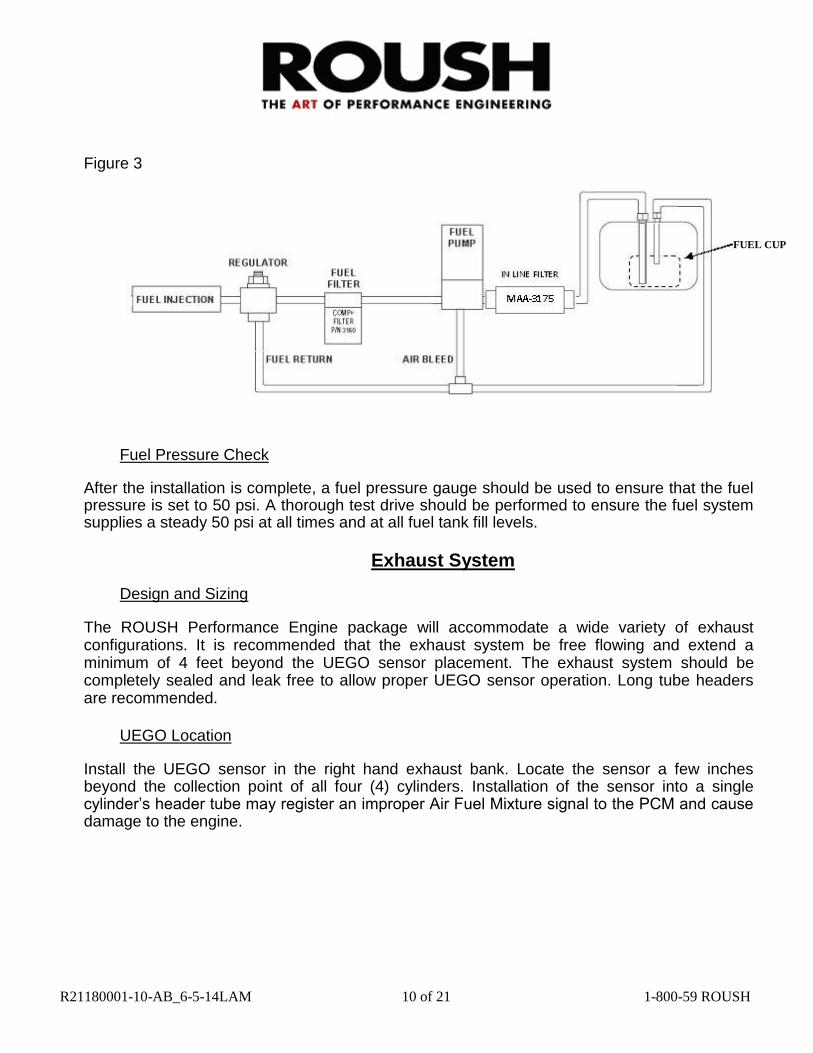
Figure 3
FUEL CUP
Fuel Pressure Check
After the installation is complete, a fuel pressure gauge should be used to ensure that the fuel pressure is set to 50 psi. A thorough test drive should be performed to ensure the fuel system supplies a steady 50 psi at all times and at all fuel tank fill levels.
Exhaust System
Design and Sizing
The ROUSH Performance Engine package will accommodate a wide variety of exhaust configurations. It is recommended that the exhaust system be free flowing and extend a minimum of 4 feet beyond the UEGO sensor placement. The exhaust system should be completely sealed and leak free to allow proper UEGO sensor operation. Long tube headers are recommended.
UEGO Location
Install the UEGO sensor in the right hand exhaust bank. Locate the sensor a few inches beyond the collection point of all four (4) cylinders. Installation of the sensor into a single cylinder’s header tube may register an improper Air Fuel Mixture signal to the PCM and cause damage to the engine.
R21180001-10-AB_6-5-14LAM 10 of 21 1-800-59 ROUSH

Figure 4 UEGO Bung and Orientation
The UEGO sensor is designed to thread into an 18mm x 1.5 nut or threaded bung (included). To ensure proper placement of the UEGO Sensor relative to the flow of exhaust gasses the thickness between the outer bung flange and the inside of the pipe should be less than 3/8”. Refer to Figure 4. The bung must be installed on the upper portion of the exhaust pipe, with the sensor tip pointing downward to ensure it will not be affected by condensation in the exhaust system at start-up.
Assembly Notes
Accelerator Cable
Install the engine side accelerator cable prior to installing the engine into the vehicle. Do not remove the throttle bodies to install the accelerator cable.
Throttle Bodies – 8 Stack
The 8 Stack throttle bodies are preset at ROUSH while on the dynamometer. Do not remove the throttle bodies, doing so will add hours to your vehicle build.
Service and Diagnostics
External LED’s
The XFI ECU features LED’s built into the case. They are a valuable tool for confirming basic ECU functions. Because they are built into the ECU, they can be used without connecting a PC to the ECU.
Power
This LED lights up when the ECU is keyed on. If this LED is not lit, the ECU will not start the engine and will not communicate with a PC. If this LED is lit when the key is on but not when you crank the engine, you have not wired the +12V SWITCHED wire in the main harness to the right place in your vehicle.
R21180001-10-AB_6-5-14LAM 11 of 21 1-800-59 ROUSH

Crank
This LED lights up when the ECU receives a crank input. It should flash whenever the engine is cranking or running. If it is not flashing, you will need to find out why before the engine will run. Check the source of the crank signal (crank pickup, distributor, stock ignition
system, etc). Also check the wiring between the ECU and the crank signal. The flashing may be so rapid that the LED will appear to be continuously lit. This is normal. If unexpected flashes occur (with engine running or stopped), it may indicate that the unused crank input has not been grounded.
Cam
In Bank-to-Bank mode, a cam input is not required. So it is normal for the cam LED to remain off.
If unexpected flashes occur (with engine running or stopped), it may indicate that the unused cam input(s) have not been grounded.
Points
This LED lights up whenever the ECU commands the ignition system to fire. Again, the flashing may be so rapid as to appear to be continuously lit. This is normal. If your engine will not start and this LED is not litwhile cranking, first check to see if the Crank LED is lit up. More often than not if your ECU is not sending a points signal, it is not seeing a crank signal as the root cause.
INJ’s
There are 8 LED’s labeled INJ A through INJ H. These are wired directly to the outputs from the 8 injector drivers. Each LED should flash when the corresponding injector is fired – which should be whenever the engine is cranking or running. In Bank-to-Bank mode, INJ A, B, C and D will flash together and INJ E, F, G and H will flash together.
If you notice one of the injector LED’s is noticeably brighter or dimmer than the rest, it may indicate that one of the injectors is not securely connected to the wiring harness. Or it may indicate that the injectors are not all the same since the brightness of these LED’s will depend on the impedance of the injectors. Higher impedance will result in brighter LED’s.
Distributor Installation and Synchronization
Distributor Rotor Replacement and Phasing
Distributor rotor phasing is the direction the rotor is pointing when a crank signal pulse is generated. A rotor that is out of phase will crossfire under the cap possibly causing hard
R21180001-10-AB_6-5-14LAM 12 of 21 1-800-59 ROUSH

engine starting and engine damage. The distributor rotor used on the ROUSH engine is adjustable for phasing. The correct rotor setting for all ROUSH EFI engines is 15° to the right of center when looking at the back side of the rotor. Refer to Figure 5. Blue thread locker should be used on the adjustment lock screw.
Figure 5
15°
0°
Distributor Installation and Adjustment
If there is ever a failure that requires the removal and re-installation of the distributor, the following guidelines should be followed:
1) Rotate the crank shaft to 55° BTDC on the compression stroke of cylinder #1. Do not rotate
the engine backwards (counterclockwise) to get to this position.
Hint: Removing all 8 spark plugs will allow the crankshaft to rotate freely.
2) Verify the rotor phase adjustment is at 15° as per the previous section. Refer to Figure 5.
R21180001-10-AB_6-5-14LAM 13 of 21 1-800-59 ROUSH

3) Install the distributor into the block so that the #1 reluctor points directly to the center of the magnetic pick-up when the distributor is fully seated into the oil pump drive / cam gear.
4) Tighten the distributor hold down clamp bolt. Plug the distributor wire harness connector
into its mating connector in the crank signal connector.
Setting Base Ignition Timing
Start the engine and allow it to stabilize at operating temperature. Connect a timing light to the #1 spark plug wire. Adjust the timing to the specified setting by rotating the distributor as required. Refer to Table 1 for timing specs. Recheck timing after the distributor is re-tightened.
Table 1
Engine BASE TIMING (BTC) BASE IDLE RPM
427IR 10° 1100
511IR 10° 1100
347IR 10° 1100
Firing Order
The firing order for ROUSH Fuel Injected Engines is dependent on engine family as follows:
347cid – 1-3-7-2-6-5-4-8
427cid – 1-3-7-2-6-5-4-8
511FE – 1-5-4-2-6-3-7-8
Spark Plugs and Ignition Wires
Resistor type spark plugs and suppression type ignition wires must always be used with the ROUSH Fuel Injection system. Recommended replacement parts are listed on the Specifications Sheet.
R21180001-10-AB_6-5-14LAM 14 of 21 1-800-59 ROUSH

Throttle Balance and Idle Setpoint Overview (8-Stack only)
The 8 Stack throttle bodies and linkage are preset while on the ROUSH engine dynamometer. No adjustment is required.
ROUSH Performance Engines equipped with an “8-Stack” (347IR, 427IR, 511IR) have eight (8) individual throttles that must be setup for equal airflow for proper engine operation. The throttles are properly setup during engine assembly by ROUSH, but changes to drivetrain loading in vehicle (trans/flywheel load) or disassembly/reassembly of the system will require readjustment.
The 8-Stack throttle system uses eight individual throttle plates that are connected by various linkages to a cable driven throttle actuator. A set-screw type cable anchor is supplied with the engine and is designed to fit most standard throttle cables. The anchor drops into a hole in the Bellcrank at the center of the intake manifold and wraps around it in a machined slot. The Bellcrank is designed to act as a cam that actuates the Turnbuckle Style Linkage Rods at a progressively increasing rate as the throttles are opened. The Linkage Rods are connected to a single throttle body on each bank. That single throttle body transfers its movement to the other three throttle bodies on that bank through both solid and spring loaded devices. A single throttle body of the 8 (cylinder # 8 as built by ROUSH) is equipped with a Throttle Position Sensor (TPS) for monitoring by the PCM.
Throttle Balancing
Tools needed: - Edelbrock Uni-Syn Carburetor Balancing Instrument (#4025) or equivalent - Standard and Metric Hex drivers - Flat Head Screwdriver - Two (2) long length 5/16” wrenches - 3/8” socket, 6 inch extension, and driver (1/4 drive)
The throttle bodies on the engine are divided by linkage function into three groups by their operation and/or design. At the first level the throttle bodies are grouped into four pairs or “couples”. The coupled throttle bodies are:
1 & 2 3 & 4 5 & 6 7 & 8
R21180001-10-AB_6-5-14LAM 15 of 21 1-800-59 ROUSH

These pairs are adjusted by loosening one side of the solid coupler between them using a 7/64” hex key, rotate to adjust then re-tighten.
The second level of grouping is referred to as Leader/Follower for the pairs. Refer to Figure 6.
The throttle bodies for cylinders 1 & 2 and 7 & 8 are the Leader throttles. They are driven directly by the bellcrank and hex links. They have control of the idle set speed of that bank.
The throttle bodies for cylinders 3 & 4 and 5 & 6 are the Follower throttles. They are driven by a spring linkage from the adjacent Leader throttle body. The spring linkage adjustment screw will adjust the flow of that pair of throttles.
The third level of grouping is by engine bank. The banks are referred to as “Right” for cylinders #1-4 and “Left” for cylinders #5-8. Left and Right bank airflow balance is adjusted via the Turnbuckle Linkage Rods. Refer to Figure 6.
Figure 6
NOTE: Any attempt to close a throttle body below its minimum mechanical limit will cause the other throttle bodies to open.
R21180001-10-AB_6-5-14LAM 16 of 21 1-800-59 ROUSH
LEADER FOLLOWER
4
3
8
1 5
7
6 2
LEADER FOLLOWER
RIGHT
BANK
LEFT
BANK

Initial Setup
1) Remove the air filters.
2) Warm the engine to operating temperature.
3) Using a synchronizing tool (Edelbrock Uni-Syn or equivalent) to measure the airflow through all 8 throttle bodies. Refer to Figure 7.
4) Identify the throttle body with the highest airflow and set the
flow meter to approximately 75% on the flow scale. (Note: This will be very near to the minimum adjustment setting on a Uni-Syn).
Figure 7
NOTE: During the course of adjustment, pay attention to engine speed. In some cases, opening the throttles to match others could result in excessive engine speed that will need to be immediately reduced.
Adjusting Coupled Pairs
1) Beginning with the “1 & 2” pair, measure and note the airflow reading of the #2 (closer to manifold center) throttle body.
2) Move the synchronizing tool to the #1 (outermost) throttle body and note the reading.
3) If the readings are different, loosen the center coupler at the #2 (innermost) throttle body and slightly rotate the coupler forward or back to match the other throttle body air flow reading. Refer to Figure 8 on the following page.
R21180001-10-AB_6-5-14LAM 17 of 21 1-800-59 ROUSH
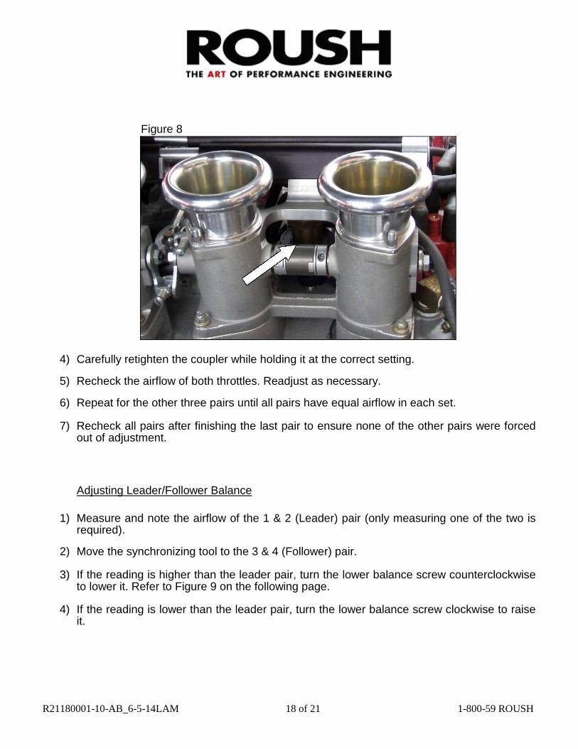
Figure 8
4) Carefully retighten the coupler while holding it at the correct setting.
5) Recheck the airflow of both throttles. Readjust as necessary.
6) Repeat for the other three pairs until all pairs have equal airflow in each set.
7) Recheck all pairs after finishing the last pair to ensure none of the other pairs were forced out of adjustment.
Adjusting Leader/Follower Balance
1) Measure and note the airflow of the 1 & 2 (Leader) pair (only measuring one of the two is
required).
2) Move the synchronizing tool to the 3 & 4 (Follower) pair.
3) If the reading is higher than the leader pair, turn the lower balance screw counterclockwise to lower it. Refer to Figure 9 on the following page.
4) If the reading is lower than the leader pair, turn the lower balance screw clockwise to raise
it.
R21180001-10-AB_6-5-14LAM 18 of 21 1-800-59 ROUSH
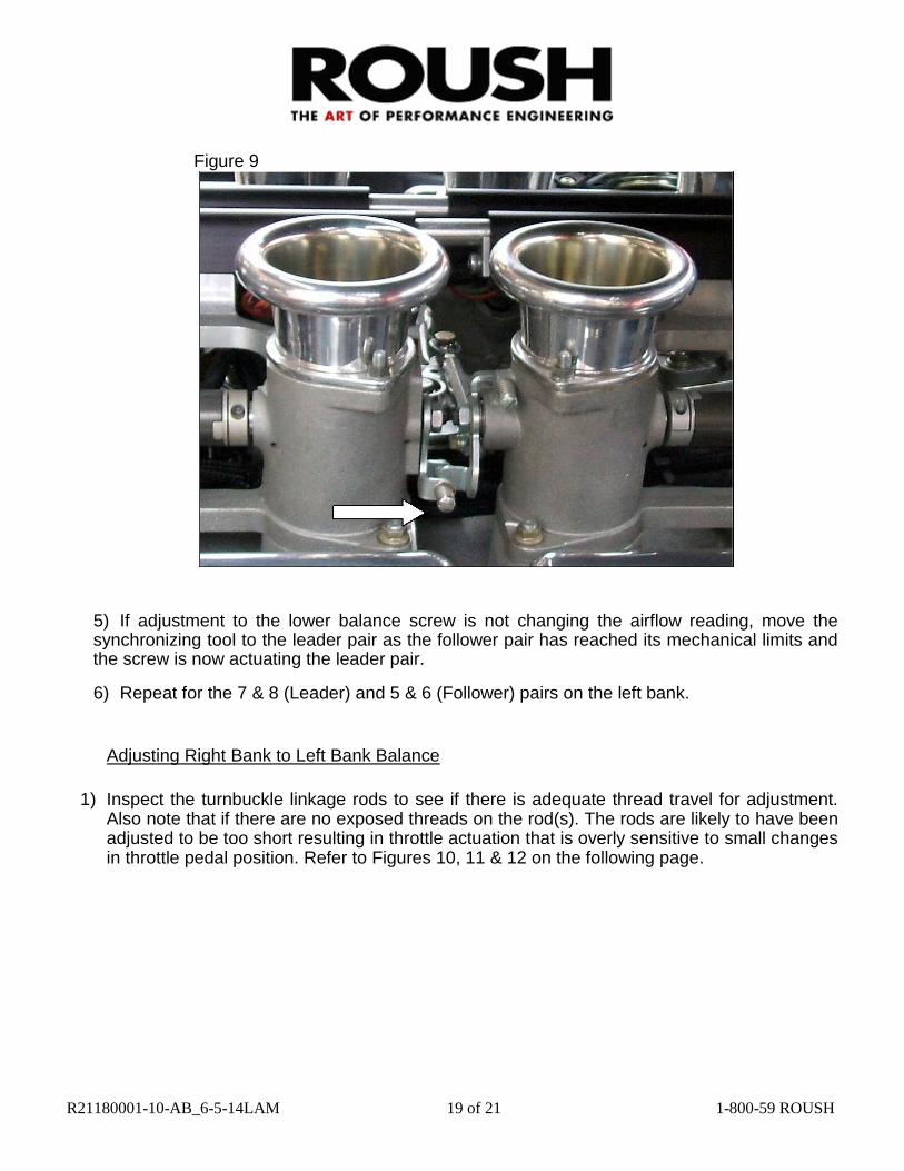
Figure 9
5) If adjustment to the lower balance screw is not changing the airflow reading, move the synchronizing tool to the leader pair as the follower pair has reached its mechanical limits and the screw is now actuating the leader pair.
6) Repeat for the 7 & 8 (Leader) and 5 & 6 (Follower) pairs on the left bank.
Adjusting Right Bank to Left Bank Balance
1) Inspect the turnbuckle linkage rods to see if there is adequate thread travel for adjustment. Also note that if there are no exposed threads on the rod(s). The rods are likely to have been adjusted to be too short resulting in throttle actuation that is overly sensitive to small changes in throttle pedal position. Refer to Figures 10, 11 & 12 on the following page.
R21180001-10-AB_6-5-14LAM 19 of 21 1-800-59 ROUSH

OK
OK
Figure 10 Figure 11
Incorrect
Figure 12
2) With the linkage rods at an adequate length, snug both lock screws at the ends of the left bank rod in a position that does not put the ball ends into a bind. The locked rod should be
able to twist back and forth about 1/6” of a turn or more.
3) Measure and note the airflow of the left bank.
4) Move the synchronizing tool to the right bank.
5) If the UEGO sensor is installed in the right hand exhaust bank, then adjust the right side
linkage rod until the right bank airflow is slightly below the left bank reading. If the UEGO sensor is installed in the left hand exhaust bank, set the left hand bank airflow lower than the right hand bank. It may be necessary to adjust the idle set screws to get to the target airflow.
6) When the proper airflow is achieved, snug both lock screws at the ends of the right bank rod
in a position that does not put the ball ends into a bind. The locked rod should be able to twist
back and forth about 1/6” of a turn or more.
R21180001-10-AB_6-5-14LAM 20 of 21 1-800-59 ROUSH

Installation Support Help Line
For assistance during the installation of this crate motor, contact the ROUSH Performance Parts Help Desk at (800) 59-ROUSH
WARRANTY
FOR ENGINE WARRANTY INFORMATION PLEASE REFER TO THE ROUSH
PERFORMANCE WEBSITE AT WWW.ROUSHPERFORMANCE.COM, OR CALL
THE ROUSH PERFORMANCE HELP DESK AT (800) 59-ROUSH R21180001-10-AB_6-5-14LAM 21 of 21 1-800-59 ROUSH