rotoropt 2 - nrel
TRANSCRIPT

By
By
ROTOROPT 2.0
15/1/15 Peter Baek, Conceptual Design

AGENDA
1. Integrated Design Challenge 2. Blade Design Components 3. RotorOpt 2.0 4. Design Example

Wind Turbine Optimization
Turbine optimization objective:
Minimize cost of energy.
Simple, but
Each manufacturer has a different design philosofy, technology and suppliers.
Manufacturers use platforms with varying rotor and drive train configurations to bring down costs.

Wide range of possible designs
Blade optimization:
Maximize AEP within load envelope.
Mimimize mass/moment for given AEP
Make the right compromizes
Cos
t
Performance

RotorOpt 1.0 (2008)
First generation blade optimizer
Weak structural coupling
Few load cases
Serial perturbations
Desktop computer power

Main Blade Design Components
LM Standard Laminate Plan • Parametric, Scalable &“Optimizable” • Ensures 80% production ready
structural design • Draws on 30+ years of experience • Used directly by LM tools
LM Airfoil Families • Holds all the latest validated airfoils (shapes & polars) • All airfoils validated in LM Wind tunnel • Different add-on concepts available (T-Spoiler, VG’s, Serrations, etc)
LM Material Database • All validated materials available
for production • Including the Material Design
Values (strength) • Based on extensive testing.
Blade Design

Airfoil Blender
Smooth airfoil data from reliable source
Access to large database of measurements for LM-airfoils (1.5∙106 < Re < 6∙106) with addons (VGs, serrations, T-spoiler)
Arranged cleverly for the optimizer to be able transition smoothly from high to low lift airfoils

Load Calculation with LM-Flex
Standard IEC load cases
20-100 IEC load cases (normal operation and extreme load cases) are simulated with LM-Flex (based on FLEX5)
LM-Flex can be swapped with Hawc2 for higher fidelity modelling – but 50-100x slower
Post processing using rain flow counting and extreme value extrapolation
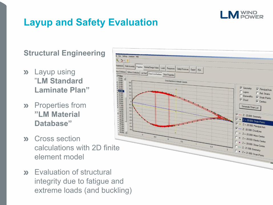
Layup and Safety Evaluation
Structural Engineering
Layup using ”LM Standard Laminate Plan”
Properties from ”LM Material Database”
Cross section calculations with 2D finite element model
Evaluation of structural integrity due to fatigue and extreme loads (and buckling)
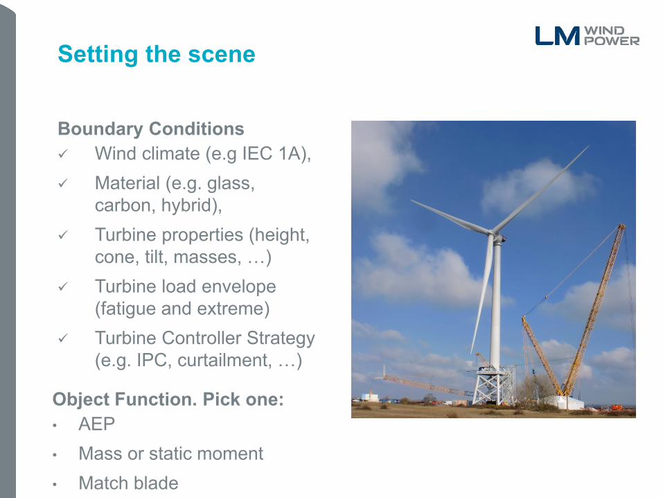
Setting the scene
Boundary Conditions Wind climate (e.g IEC 1A), Material (e.g. glass,
carbon, hybrid), Turbine properties (height,
cone, tilt, masses, …) Turbine load envelope
(fatigue and extreme) Turbine Controller Strategy
(e.g. IPC, curtailment, …)
Object Function. Pick one: • AEP • Mass or static moment • Match blade

Design Variables
Distributions of: Chord, Twist, Relative thickness, Airfoil families, Airfoil addons (e.g. VGs), Blade centerline (x & y), Ply groups.
Scalars Blade length, Rotation Speed
Constraints
Maximum loads, Tip-to-tower clearance Minimum AEP, Maximum mass/moment, Minimum structural safety (plys, glue,
bushings, etc.), Layup rules (e.g. tapering contraints), Mininumum aerodynamic safeties, Maximum sound emission, Blade frequencies, Geometric constraints (lightning
protection, maximum curvatures)

One Design Evaluation
3D Geometry
Material Layup
Calculate Loads
Safeties
Steady State BEM AEP
Noise
Turbine Loads Blade deflection
Ply safety Bushing safety Ply rules check
Curvatures, Lightning protection
Des
ign
varia
bles
Airfoil Blending
Mass & moment Frequencies
Objective/ Constraints

Parallel Tasks in one Evaluation
Calculate Loads
time

Many parallel evaluations
x
x1 + dx1
...
f,g
df/dx1 , dg1/dx1 , ....
...
time
Inhouse HPC Cluster
Hardware
48 nodes (8 cores each) InfiniBand network Scalable
Linux operating system Sun Grid Engine Python
Software

LM101
Conceptual Design Demonstrator

LM101
Conceptual Design Demonstrator
101m Blade length
101m/s Tip speed
10.1 MW Rated power
Wind Class IEC 1A
Carbon fiber technology
Collective Pitch Control, Variable Speed
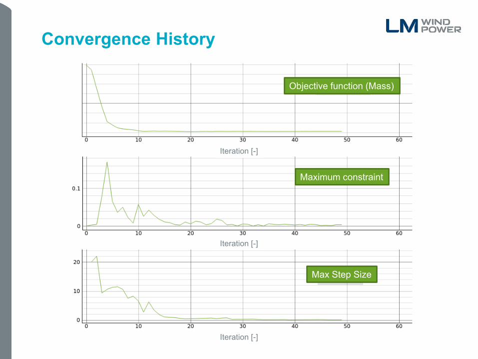
Convergence History
Objective function (Mass)
Maximum constraint
Max Step Size
Iteration [-]
Iteration [-]
Iteration [-]

Convergence History
Design Variables Blade Definition
Red Green Objective Max AEP Min mass Constraint ... -2% AEP

Convergence History
Design Variables Blade Definition
Red Green Objective Max AEP Min mass Constraint ... -2% AEP

Mass vs. Annual Energy Production
M
ass
[kg]
Mas
s [%
]

Next steps
Faster, better accuracy, bigger
Faster with frequency domain load calculations.
More precise with Hawc2 and FEM shell/solid model in the loop.
Tap into cloud computing ressources

Conclusion
Rapid Design Process
There is no universal optimum blade geometry.
RotorOpt is a fast way to get the best compromize between structure and aerodynamics for the specific customer case
RotorOpt uses validated blade design components to minimize project risk with an almost production ready output

Thank you for your time
Contact details: Head quarters:
Peter Baek LM Wind Power Senior Engineer Jupitervej 6 Conceptual Design 6000 Kolding
Denmark
Tel +45 79 84 00 00 Fax +45 79 80 00 01
E [[email protected]] E [email protected] W lmwindpower.com
Note: The contents of this presentation are confidential and may not be copied, distributed, published or reproduced in whole or in part, or disclosed or distributed by recipients to any other person.