rotor removal and installation - patriot products, inc
TRANSCRIPT
Maintenance Instructions
Rotor Removal And Installation
Most situations, such as clearing jams or removing the chipper-knife, do
not require removal of the rotor. Please refer to the instructions, for
these situations, located elsewhere in this manual.
Under normal circumstances, it is only necessary to remove the rotor, if
you are replacing the y-hammers or the rotor assembly. If you have a
different situation, that you feel requires you to remove the rotor,
contact Patriot Products, before proceeding; it can save you a lot of time
and frustration.
Your Patriot Electric Chipper-Shredder-Vac (CSV) is designed to allow
for it to be easily maintained by the average person. However,
disassembling and, more importantly, reassembling the unit is a
formidable undertaking that, if done hastily or carelessly, can render
your machine inoperable or unsafe. Therefore, only disassemble your
chipper-shredder if it is truly necessary; doing so, only if you are
capable and willing, to reassemble it properly, per the instructions
provided.
Tools – Required
The following tools are required specifically to properly complete the
rotor removal and installation procedures for your unit:
[ ] Work-gloves
[ ] 5/8” combination-wrench
Note: Completion of this procedure requires you to follow the Outboard
-Bearing and Fan-Housing Removal and Installation Procedures.
Please also refer to the required and recommended tools sections in the
Outboard-Bearing and Fan-Housing Removal and Installation
Procedures, prior to continuing.
Always use the proper hand-tools, for assembly. Personal-injury can
result through the use of the improper type-or-size of tool, as well as
while using a worn-or-damaged tool, that may slip off of hardware
being tightened.
In addition, improper tools may damage hardware, making it difficult or
impossible to properly tighten the hardware. Finally, damaged
hardware will discourage timely-and-proper maintenance, which could
lead to serious personal-injury or property-damage.
Common examples of improper assembly tools are: adjustable open-end
wrenches and toothed gripping-pliers.
page 1
Serious personal-injury to the
operator or bystanders, as well
as damage to equipment or
property, can occur, if all safety
and assembly instructions,
provided with this product, are
not followed.
You MUST read, understand,
and comply with all of the
safety, assembly, and operating
instructions in this manual,
BEFORE you attempt to
operate your chipper-shredder-
vac.

Maintenance Instructions
Rotor Removal And Installation (continued)
Tools – Recommended
The following tools are recommended specifically to properly complete
the rotor removal and installation procedures for your unit:
[ ] Anti-seize compound, to coat the motor-shaft, before reassembly
[ ] Patriot Electric Rotor-Removal Tool
[ ] Oil or grease, a small amount, to apply to forcing bolt of rotor-
removal tool, during rotor removal
[ ] Wood board (or similar item), 2” x 2” x 36”, to keep rotor from
rotating, during rotor removal
Removal Procedure
1. Complete the Outboard-Bearing & Fan-Housing Removal
Procedure, located elsewhere in this manual, to expose the rotor for
removal.
WARNING: DO NOT proceed to the next step, without verifying that the
chipper-knife has been removed from the rotor. Attempting to remove
the rotor with the chipper-knife attached and fully exposed,
unnecessarily exposes you to a severe laceration hazard.
page 2
MOVING PARTS HAZARD
Serious personal-injury can
occur, if you come into contact
with the chipper-shredder’s
moving parts.
Turn off the motor, disconnect
the electrical-cord, and wait for
the rotor to come to a complete
stop, before attempting to
service the chipper-shredder.
2. Note: The high torque, applied during the rotor-removal procedure,
will rotate the rotor. To minimize the risk of personal injury, we
highly recommend that you use an object, such as the recommended
2” x 2” x 36” wood board, to keep the rotor from turning.
Place an object, such as a 2” x 2” x 36” wood board, see shaded
object in illustration, down through the shredder-hopper. Wedge the
object between the rotor’s hub and one (1) of the y-hammer shafts.
This will help prevent the rotor from turning, during the rest of the
procedure.
SEVERE LACERATION
HAZARD
The chipper-knife is sharp,
even if you think it’s dull.
DO NOT proceed to step 2, if
the chipper-knife was not
removed, as specified during
step 1. Accidently contacting
the sharpened-edge of the
exposed chipper-knife, during
the process of removing the
rotor, can cause serious
personal-injury.

Maintenance Instructions
Rotor Removal And Installation (continued)
Removal Procedure (continued)
page 3
3. Using a 1/2” wrench, carefully remove the rotor-bolt from the
exposed-end of the rotor-shaft, as shown. Set the bolt and
corresponding lock washer aside, for reassembly later.
4. Now that the rotor-bolt has been removed, remove the object that
was placed in step 2, see shaded object in illustration, to allow the
rotor to now move. Set the object aside, for use later.

page 4
Maintenance Instructions
Rotor Removal And Installation (continued)
Removal Procedure (continued)
5. At this point, you are ready to start to remove the rotor.
Note: Since there are only a few thousandths-of-an-inch clearance,
between the motor-shaft and the inside of the rotor, you need to
provide a smooth, even, pull on the rotor. Pulling significantly more
on one side of the rotor will cause the rotor to bind against the
motor-shaft.
Note: Due to the tight tolerances and large amount of surface
contact between the motor-shaft and the inside of the rotor, it can
take a fair amount of effort to move the rotor. Factors such as how
long it’s been since the rotor was last removed, the humidity where
you live, and the moisture content of the material you process can
all contribute to surface corrosion, between the motor-shaft and
rotor.
CAUTION: DO NOT attempt to PRY the rotor off of the motor-
shaft. This will most likely only damage parts and make the
situation worse.
With a little patience and effort, you can theoretically begin to pull
the rotor off of the motor-shaft. The motor has a straight shaft with
a keyway, so it truly takes just a straight pull.
In the steps that follow, we have provided an alternative method for
pulling the rotor off of the motor-shaft.
Optional Removal Procedure
Removal Using Patriot Rotor-Removal Tool
Patriot has made every effort to design its products to be easily
maintained, by the average homeowner, using common tools. That
being said, there are occasions when a specialty tool is beneficial; while
a small investment, such tools can reduce the effort, frustration, and
time required to complete a task.
One such occasion is specifically pulling the rotor off of the motor-
shaft. It is simple in theory, but in practice, people struggle with
applying a smooth, even pull. It’s especially difficult when you’re
already frustrated or in a hurry.

Maintenance Instructions
Rotor Removal And Installation (continued)
Optional Removal Procedure (continued)
page 5
Patriot originally developed the Patriot Rotor-Removal Tool for our
own convenience, in case we needed to disassemble a unit. We have
since made several minor improvements, to make it more user-friendly.
The just-of-it is that, the Patriot Rotor-Removal Tool gives you a quick,
simple, way to apply the smooth, even, pull, required to remove the
rotor from the motor-shaft.
The steps that follow depict how to use the Patriot Rotor-Removal Tool.
The parts described are provided, if you purchase the Patriot Rotor-
Removal Tool.
6. Gently insert the main Rotor-Removal Tool components in the
following order:
a. 1/4” diameter x 1 3/4” dowel, rounded end first
b. 3/8” diameter x 4” dowel, rounded end first
c. 7/16” x 1 1/2” forcing bolt
Note: The 3/8” diameter x 1” dowel, provided, is not used in this
step.
Note: For this step, just barely start to thread the forcing-bolt, into
the end of the rotor-shaft; it should turn very easily.
7. Apply a small amount of lubricant to the threads of the forcing bolt
and hand tighten. It should turn very easily, until only
approximately 1” of threads remain exposed, as shown.
Note: For this step, the forcing-bolt should only be hand tightened.
This allows the two (2) dowels, inserted in step 6, to properly
position themselves, without damaging the threads in the motor-
shaft or rotor-shaft. Also, you want to make sure there is plenty of
thread engagement, before you apply any significant torque to the
forcing bolt, this will prevent stripping the threads out of the end of
the rotor-shaft.

page 6
Maintenance Instructions
Rotor Removal And Installation (continued)
Optional Removal Procedure (continued)
9. Using a 5/8” wrench, slowly begin to tighten the forcing bolt.
Note: When the rotor begins to move, remove the object that was
placed in step 8. You will need to watch to see that the y-hammers
do not get caught against the center plate. Refer to the shaded areas
in the illustration. The next couple of steps describe how to address
this situation, to prevent damage to the chipper-shredder.
Note: DO NOT apply a torque in excess of 27 ft-lbs to the forcing
bolt. If you’re applying this much torque and the rotor is not
moving, there is most likely some sort of interference. If you cannot
find the interference, contact Patriot at 1-800-798-2447, before
proceeding.
8. Note: The high torque, applied during the optional rotor-removal
procedure, will rotate the rotor. To minimize the risk of personal
injury, we highly recommend that you use an object, such as the
recommended 2” x 2” x 36” wood board, to keep the rotor from
turning.
Place an object, such as a 2” x 2” x 36” wood board, see shaded
object in illustration, down through the shredder-hopper. Wedge the
object between the rotor’s hub and one (1) of the y-hammer shafts.
This will help prevent the rotor from turning, during the rest of the
procedure.
10. If a y-hammer is going to catch on the center-plate, stop turning the
forcing bolt and rotate the y-hammer out of the way, as depicted in
the illustration. Once you are certain that the y-hammers are clear of
the center-plate, continue to remove the rotor, by turning the forcing
bolt with the 5/8” wrench. After about an inch of travel, the head of
the forcing bolt will be touching the top of the rotor-shaft, as shown.
The rotor should be freed up; enough so, that you can pull it off by
hand. If this is not the case, make sure that you do not have a y-
hammer caught on the center-plate or some other interference. If no
interference is found, proceed to the next step.
Note: You can cause irreparable damage to the chipper-shredder,
including bending the motor-shaft, if you tighten the forcing bolt
while there is interference, between a y-hammer and the center-
plate. For best results, be patient and attentive, when tightening the
forcing bolt.

Maintenance Instructions
Rotor Removal And Installation (continued)
Optional Removal Procedure (continued)
page 7
11. If you were able to pull the rotor off by hand, in the previous step,
jump ahead to step 15. Otherwise, use a 5/8” wrench to remove the
forcing bolt from the rotor-shaft, as shown.
Note: For the same reasons you are using this optional removal
procedure, there still may be enough resistance between the motor-
shaft and the inside of the rotor, that you’ll need to continue to use
the forcing bolt to remove the rotor.
12. Gently insert the final Rotor-Removal Tool components in the
following order:
a. 3/8” diameter x 1” dowel, rounded end first
b. 7/16” x 1 1/2” forcing bolt
Note: For this step, just barely start to thread the forcing-bolt, into
the end of the rotor-shaft. It should turn very easily.
13. Apply a small amount of lubricant to the threads of the forcing bolt
and hand tighten. It should turn very easily, until only
approximately 1” of threads remain exposed, as shown.
Note: For this step, the forcing-bolt should only be hand tightened.
This allows the three (3) dowels, inserted previously, to properly
position themselves, without damaging the threads in the motor-
shaft or rotor-shaft. Also, you want to make sure there is plenty of
thread engagement, before you apply any significant torque to the
forcing bolt, this will prevent stripping the threads out of the end of
the rotor-shaft.

page 8
Maintenance Instructions
Rotor Removal And Installation (continued)
Optional Removal Procedure (continued)
14. Using a 5/8” wrench, slowly begin to tighten the forcing bolt.
Note: As before, when the rotor begins to move, you will need to
watch to see that the y-hammers do not get caught against the center
plate.
Note: DO NOT apply a torque in excess of 27 ft-lbs to the forcing
bolt. If you’re applying this much torque and the rotor is not
moving, there is most likely some sort of interference. If you cannot
find the interference, contact Patriot at 1-800-798-2447, before
proceeding.
As before, if a y-hammer is going to catch on the center-plate, stop
turning the forcing bolt and rotate the y-hammer out of the way, as
depicted in the illustration. Once you are certain that the y-hammers
are clear of the center-plate, support the rotor before continuing.
Note: The rotor weighs roughly 15 pounds and will ruin your day
if it falls on your hand or foot!
Continue to remove the rotor by turning the forcing bolt with the
5/8” wrench. After about 1/2” of travel, be prepared for the rotor to
come off of the motor-shaft just before the head of the forcing bolt
touches the end of the rotor-shaft, as shown.
Note: You can cause irreparable damage to the chipper-shredder,
including bending the motor-shaft, if you tighten the forcing bolt
while there is interference between a y-hammer and the center-plate.
For best results, be patient and attentive, when tightening the
forcing bolt.
15. Once the rotor has been removed, use the 5/8” wrench to remove the
forcing bolt from the end of the rotor-shaft and immediately locate
the following four (4) items:
a. 1/4” diameter x 1 3/4” dowel (may still be in motor-shaft)
b. 3/8” diameter x 4” dowel
c. 3/8” diameter x 1” dowel
d. 7/16” x 1 1/2” forcing bolt
Take a moment to store these four (4) components somewhere, for
future use. Also, set the rotor aside.

Maintenance Instructions
Rotor Removal And Installation (continued)
Optional Removal Procedure (continued)
page 9
16. Before you move on to other tasks, it will be beneficial to locate the
rectangular key, that prevents the rotor from spinning, relative to the
motor-shaft, see grayed objects in illustration. The key measures
3/16” x 3/16” x 1 1/4”. As indicated in the illustration, after the
rotor was removed, the key typically is stuck in the keyway of either
the motor-shaft or rotor-hub. So you don’t accidentally lose it,
locate and remove the key. Place the key with the rotor-bolt and
lock washer, removed in step 3, for reassembly later.
2. Insert the rectangular key, from Rotor Removal Procedure step 16,
into the keyway of the rotor. Push the key as far into the rotor as
possible, as depicted by the grayed surface in the illustration.
Note: Making sure you push the key in as far as possible, makes
reassembly a much easier task.
Installation Procedure
1. Before you attempt to install the rotor, it is very important to make
sure that the motor-shaft, see the grayed surfaces in the illustration
for location, is clean and smooth.
Note: There are only a few thousandths-of-an-inch clearance,
between the motor-shaft and the inside of the rotor. Therefore,
scratches or nicks in the shaft’s surface, as well as debris or rust on
the shaft’s surface, will make the rotor difficult to install.
Use a fine sand-paper, 240-grit or finer, to clean up the exposed-end
of the rotor-shaft. Wipe off the motor-shaft, then manually rotate
the shaft, so that the keyway faces down, as shown. Apply a thin
coating of anti-seize compound to the shaft. The anti-seize
compound will make it easier for the rotor to slide onto the shaft and
help facilitate future rotor removal.
page 10
Maintenance Instructions
Rotor Removal And Installation (continued)
Installation Procedure (continued)
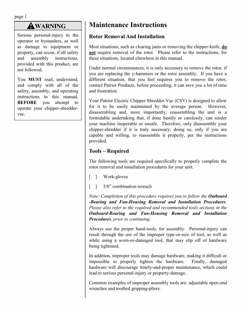
3. Orient the rotor and align it with the motor-shaft, as shown. This
orientation has the keyway in the rotor facing down, just like the
keyway in the motor-shaft.
4. Attempt to get the rotor started onto the end of the motor-shaft.
Note: As with the rotor removal procedure, you will need to watch
to see that the y-hammers do not get caught against the center plate;
refer to the grayed areas in the illustration.
If a y-hammer is going to catch on the center-plate, as depicted in
the illustration, rotate the y-hammer out of the way. Once you are
certain that the y-hammers are clear of the center-plate, continue to
push the rotor onto the motor-shaft. After about 3/4” of travel, the
rotor is likely to stop moving, because the end of the motor-shaft
will hit the key you placed inside of the rotor. This is perfectly
normal because the keyways in the rotor and motor-shaft are not
currently aligned. The next step addresses this situation.
5. To align the keyways in the rotor and motor-shaft, insert a small
screwdriver, refer to the grayed object in the illustration, through the
louvered cover on the back of the motor until it contacts the motor’s
cooling fan. Hold the screwdriver steady and slowly rotate the rotor,
until you feel the key in the rotor catch the keyway in the motor-
shaft. Once this happens, you can continue to slowly push the rotor
onto the motor-shaft.

Maintenance Instructions
Rotor Removal And Installation (continued)
Installation Procedure (continued)
page 11
6. Attempt to finish pushing the rotor onto the motor-shaft.
Note: As with mentioned earlier, you will need to watch to see that
the y-hammers do not get caught, against the center plate. Refer to
the shaded areas in the illustration.
If a y-hammer is going to catch on the center-plate, as depicted in
the illustration, rotate the y-hammer out of the way. Once you are
certain that the y-hammers are clear of the center-plate, continue to
push the rotor onto the motor-shaft. When you have pressed the
rotor onto the motor-shaft as far as possible and there are no
interferences, proceed to the next step.
7. The illustration depicts the rotor fully seated on the motor-shaft.
Note: You should be able to manually rotate the rotor in a complete
circle, without any interferences. If any interferences are
encountered, repeat step 6.
Once you can manually rotate the rotor one complete revolution and
there are no interferences, proceed to the next step.
8. Another quick check to see that the rotor is fully seated on the motor
-shaft is to measure the distance from the face of the center-plate to
the face of the rotor-plate. Refer to grayed surfaces in the
illustration.
Note: Don’t overthink this step and think you’ve found a problem
where one doesn’t exist. This is just a quick reference measurement
to reassure you you’re ready for the next step.
If you’re measurement is 1 5/8” or just under, proceed to the next
step. If you’re measurement is 1 11/16” or greater, recheck Rotor
Installation Procedure steps 1 through 7 to see if you can find the
problem. If you’ve retraced your steps and you’re measurement is
still 1 11/16” or greater, contact Patriot at 1-800-798-2447, before
proceeding.

page 12
Maintenance Instructions
Rotor Removal And Installation (continued)
Installation Procedure (continued)
9. Install the rotor-bolt and lock washer into the rotor-shaft, until they
contact the motor shaft. Begin to tighten the rotor-bolt by hand to
make sure it is properly threaded into the end of the motor shaft.
Continue to hand tighten the rotor-bolt until the lock washer is in
contact with both the head of the bolt and the end of the rotor-shaft.
Note: Failure to properly thread the rotor-bolt into the end of the
motor shaft can cause irreparable damage to the threads in the
motor shaft.
10. Note: The high torque, applied during the rotor-installation
procedure, will rotate the rotor. To minimize the risk of personal
injury, we highly recommend that you use an object, such as the
recommended 2” x 2” x 36” wood board, to keep the rotor from
turning.
Place an object, such as a 2” x 2” x 36” wood board, see shaded
object in illustration, down through the shredder-hopper. Wedge the
object between the rotor’s hub and one (1) of the y-hammer shafts.
This will help prevent the rotor from turning, during the rest of the
procedure.
11. Securely tighten the rotor-bolt using a 1/2” wrench.
Recommended torque: 25 - 27 ft-lb
Maintenance Instructions
Rotor Removal And Installation (continued)
Installation Procedure (continued)
page 13
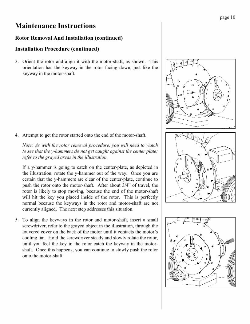
12. Now that the rotor-bolt has been securely tightened, remove the
object that was placed in step 10, see shaded object in illustration.
Set the object aside, for future use.
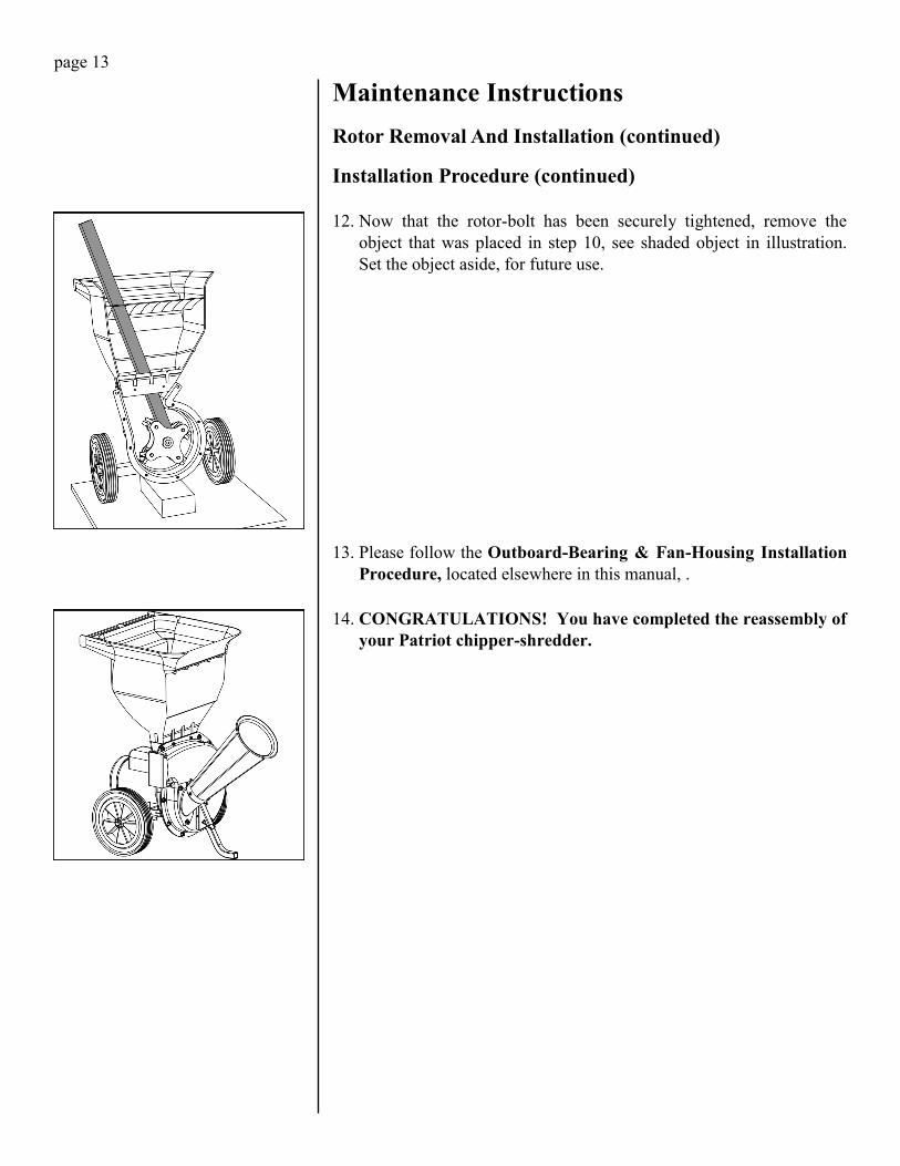
13. Please follow the Outboard-Bearing & Fan-Housing Installation
Procedure, located elsewhere in this manual, .
14. CONGRATULATIONS! You have completed the reassembly of
your Patriot chipper-shredder.