rotavator buffalo 36 ( b-36 ) - howardmy.comsite.howardmy.com/clients/howardmy/rotavator buffalo...
TRANSCRIPT
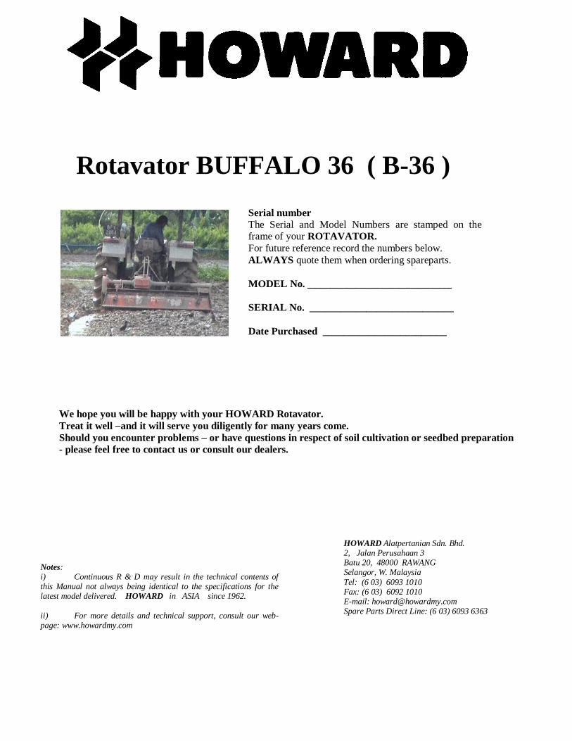
Notes: i) Continuous R & D may result in the technical contents of this Manual not always being identical to the specifications for the latest model delivered. HOWARD in ASIA since 1962. ii) For more details and technical support, consult our web-page: www.howardmy.com
Rotavator BUFFALO 36 ( B-36 )
We hope you will be happy with your HOWARD Rotavator.
Treat it well –and it will serve you diligently for many years come.
Should you encounter problems – or have questions in respect of soil cultivation or seedbed preparation
- please feel free to contact us or consult our dealers.
Serial number The Serial and Model Numbers are stamped on the frame of your ROTAVATOR. For future reference record the numbers below. ALWAYS quote them when ordering spareparts. MODEL No. ____________________________ SERIAL No. ____________________________ Date Purchased ________________________
HOWARD Alatpertanian Sdn. Bhd. 2, Jalan Perusahaan 3 Batu 20, 48000 RAWANG Selangor, W. Malaysia Tel: (6 03) 6093 1010 Fax: (6 03) 6092 1010 E-mail: [email protected] Spare Parts Direct Line: (6 03) 6093 6363
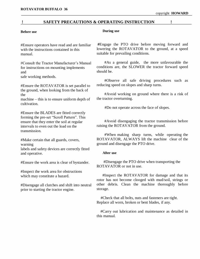
During use
#Engage the PTO drive before moving forward and
lowering the ROTAVATOR to the ground, at a speed
suitable for prevailing conditions.
#As a general guide, the more unfavourable the
conditions are, the SLOWER the tractor forward speed
should be.
#Observe all safe driving procedures such as
reducing speed on slopes and sharp turns.
#Avoid working on ground where there is a risk of
the tractor overturning.
#Do not operate across the face of slopes.
#Avoid disengaging the tractor transmission before
raising the ROTAVATOR from the ground.
#When making sharp turns, while operating the
ROTAVATOR, ALWAYS lift the machine clear of the
ground and disengage the PTO drive.
After use
#Disengage the PTO drive when transporting the
ROTAVATOR or not in use.
#Inspect the ROTAVATOR for damage and that its
rotor has not become clooged with mud/soil, strings or
other debris. Clean the machine thoroughly before
storage.
#Check that all bolts, nuts and fasteners are tight.
Replace all worn, broken or bent blades, if any.
#Carry out lubrication and maintenance as detailed in
this manual.
ROTAVATOR BUFFALO 36
copyright HOWARD
! SAFETY PRECAUTIONS & OPERATING INSTRUCTION !
Before use
#Ensure operators have read and are familiar
with the instructions contained in this
manual.
#Consult the Tractor Manufacturer‟s Manual
for instructions on mounting implements
and
safe working methods.
#Ensure the ROTAVATOR is set parallel to
the ground, when looking from the back of
the
machine – this is to ensure uniform depth of
cultivation.
#Ensure the BLADES are fitted correctly
forming the pre-set “Scroll Pattern”. This
ensure that they enter the soil at regular
intervals to even out the load on the
transmission.
#Make certain that all guards, covers,
warning
labels and safety devices are correctly fitted
and operative.
#Ensure the work area is clear of bystander.
#Inspect the work area for obstructions
which may constitute a hazard.
#Disengage all clutches and shift into neutral
prior to starting the tractor engine.

NEVER -Use your Rotavator unless the safety guards are in place.
-Check oil levels whilst the implement is running.
- Attempt to clear any obstruction around the spindle or carry out cleaning, lubricating,
adjustments or repairs to a mounted implement, unless the tractor engine is stopped and the
implement is propped correctly or resting on firm level ground.
-Leave the tractor seat unless the implement is lowered, the PTO drive disengaged, the gear
shift in neutral, the brake applied, the engine stopped and the ignition key removed.
ROTAVATOR BUFFALO 36
copyright HOWARD
Always
- Wear safety or substantial footwear.
- Avoid loose clothing which may be caught in moving parts.
- Wear earmuffs or earplugs. Prolonged exposure to noise can cause impairment or loss of hearing.
- Wear gloves when handling worn implements or parts with sharp edges.
- Use the implement only for the purpose for which it was designed and in accordance with the
instructions contained in this manual.
- Ensure the Rotavator is not operated by children or untrained persons.
- Interpret “ left” or “right” as the left or right hand of the operator when sitting on the tractor seat and
facing forward.
BE A SAFE OPERATOR
BY THINKING – BEFORE
ACTING
Rotavation is the direct application of tractor
engine power through a rotor and hoe blades of a
special design to soil preparation in establishing the ideal growth conditions for seedlings and
seeds.
The working of the soil by Rotavation gives
control over weeds and serves to mix fertiliser,
lime, crop residues and other organic matter with
the soil, producing good physical conditions for composting, formation of humus and rapid seed
germination.
Compared with other methods of soil preparation
(disc or mouldboard ploughs), Rotavators
provide a superior and even soil mixing rate throughout the tilling depth, allowing the soil
with the best structure to remain in the surface
layers where it is most needed.
The texture of rotavated soil absorbs and retains
upto three times as much moisture as conventionally ploughed soil. This is
particularly valuable during dry seasons and in
areas with low rainfall. Surface run-off and soil
erosion is considerably minimised on rotavated land.
Fine, medium or coarse tilth can be obtained to suit the crop, the soil and the climate - in
accordance with recognised principles of
agricultural soil management.
HOWARD invented Rotavators - and has been
actively involved in mechanisation of soil
preparation in Southeast Asia since 1962.
FLEXIBILITY of ROTAVATION
Farmers will know when the timing is right for soil preparation, and will know the condition of the land, the purpose and type of tilth required.
Rotavation allows optimal possibilities and combinations to achieve the results desired:
a) Rotor speed (single speed or selectatilth speed gearbox)
b) Blade configuration (4 or 6 per flange)
c) Trailing board position (lowered or raised) c) Length of "bite" (tractor travel speed)
LIGHT SOILS are inclined to disintegrate, resulting in loss of water retention capability. As such it is recommended to rotavate light soil areas before drying out - and choose a coarse tilth, i.e. slow rotor speed, raised trailing board and fast
tractor speed.
CLAY SOILS should not be rotavated when too wet (balling up) nor too dry (dust), and should generally be worked to a finer tilth, using above parametres.
How fast can I rotavate?
Tractor speeds of 3 - 6 km/hour will apply to most conditions and will provide 0.5 - 1.0 ha prepared land per hour.
Does a Rotavator cause a hard soil pan?
Unlike a plough, the weight of the machine does not rest on the soil-engaging cutting edges, and the rotating blades exert no
downward pressure. The scroll pattern of the blade configuration provides forward momentum thereby also reducing the tractor horsepower required. Rotavator blades are scientifically shaped to have a cutting and lifting action, with the heel of
the blade never wholly touching the soil at any stage.
ROTAVATOR BUFFALO 36
copyright HOWARD
PRINCIPLE OF ROTAVATION
What is ROTAVATION?

ROTAVATOR BUFFALO 36 copyright HOWARD
Does rotavation cause erosion?
Any soil-engaging implement carelessly used can cause erosion. But a sheedbed produced by rotavatoin will
absorb and retain three time as much rainfall as soil cultivated by ploughs.
Does rotavation increase weeds?
In a controlled way, yes, by finely chopping and providing ideal growth conditions for weeds. But
rotavatoin also provides the answer – and the best known method of mechanical weed control. Eradicate
perennial weeds during a fallow period by letting the Rotavator bring the roots to the surface to wither and
die. Grass kill and mulch is easily obtained at controlled depths, making the Rotavator useful for multiple
agricultural purpose.
SPECIFICATION OF YOUR ROTAVATOR
Specification B-36/155 B-36/180 B-36/205 B-36/230 B-36/255
Working width, cm 155 180 205 230 255
Working depth, cm 18
For Tractor, Hp 45+ 55-105
Three point linkage CAT 1 / 11
Universal driveshaft A8 with FF4 Slip Clucth
Gearbox Multispeed
Rotor speed at 540 rpm PTO 166 / 203 / 144 / 235 rpm
Side drive Chain and Sprockets
Number of blades 36 42 48 54 60
Offset,max,cm Center only
Weight, Kg 470 510 550 590 630
New Machine
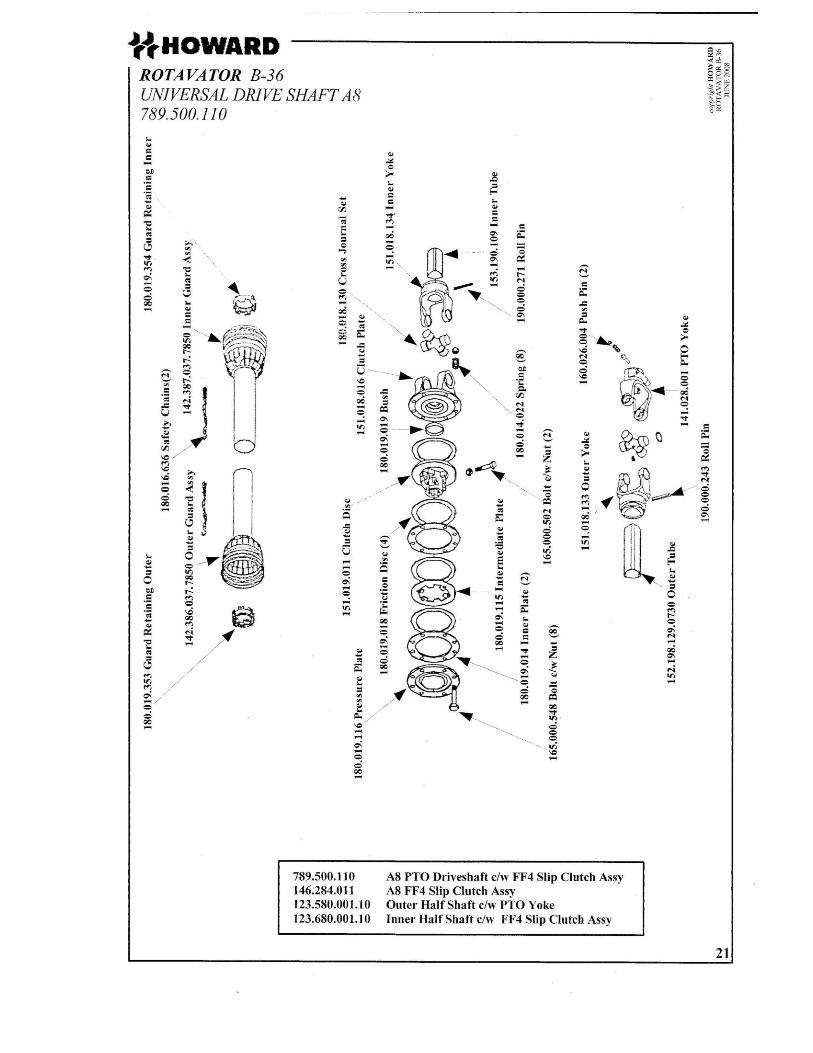
Power Take-Off Drive Shaft & Safety Device
The ROTAVATOR is supplied with an A8 PTO Drive Shaft complete with FF4 non-asbestos fibre-disc Slip
Clutch. For transport reason, the outer half shaft c/w PTO Yoke is taken off and must be refitted before use.
ROTAVATOR BUFFALO 36 copyright HOWARD
Lubrication & General
With the ROTAVATOR standing level, ensure the following preparatory work has been done:
1)The chaincase filled to the level plug (1.75L / 3 pints ). Use SEA 140 gear oil.
2)The gearbox filled to the dipstick mark (2.8L / 5 pints ). Use SEA 140 gear oil.
3)All oil and grease points to be lubricated.
4)All bolts and nuts tightened ( re-tighten after 8 hours‟ works )
SERIOUS DAMAGE CAN RESULT FROM FAILURE TO CARRY OUT THE
ABOVE PROCEDURES.

Fig. 1
Fig. 2
ROTAVATOR BUFFALO 36 copyright HOWARD
COMMISSIONING OF YOUR PTO DRIVEN ROTAVATOR
Your ROTAVATOR has been designed to work in a wide variety of conditions, and is a very simple
machine to use. The following adjustments will ensure optimum performance in all conditions.
Attaching the Rotavator to the tractor
The PTO Drive Shaft musr be set to a safe working length to ensure the inner shaft does not “bottom” or
separate from the outer shaft under all conditions of use and transport.
To determine the correct mounting position: With the Rotavator on a firm level surface, the Depth control
equipment should be adjusted until the Gearbox Input Shaft is horizontal (see Fig. 1)
Position the tractor at a distance from the Rotavator to give 12 cm minimum engagement of
the inner half of the PTO Drive Shaft in the outer half when connected to the tractor. This
establishes the safe working length of the PTO Drive Shaft for connection to the tractor.
Position the tractor lower link ball joints in line with the Hitch Pins' holes in the Mounting
Brackets (see Fig. 2). Connect the tractor lower links, left hand link first, securing with
Hitch Pins and Cotter Assemblies, adjusting the right hand tractor lift arm if necessary. Fit
the tractor upper link and secure. Attach the PTO Drive Shaft to the tractor ensuring the
quick release pin engages the spline shaft groove. Attach the PTO Drive Shaft Guard
Chains to the tractor and Rotavator.

Fig. 3
Fig. 4
ROTAVATOR BUFFALO 36 copyright HOWARD
Attach stabilizer bars or check chains to limit sway to 3 cm. Adjust tractor linkage to level the Rotavator
laterally and longitudinally (see Fig. 3)
Before engaging the tractor PTO, lift the Rotavator on the hydraulic lift linkage until the lowest cutting
adges of the blades are 230mm above ground level and set the limit stop on the hydraulic lift control
quadrant (see Fig. 4)
Finally check that during transport and use, the PTO Drive Shaft does not “bottom” or separate and that the
maximum height of 230mm is not exceed.
Should it not be possible to obtain the aforementioned setting with your tractor, SEEK ADVICE; it may be
necessary to reduce the length of the PTO Drive Shaft by cutting of equal amount from both Inner & Outer
Cardan Tubes with a hacksaw.
ROTAVATOR BUFFALO 36 copyright HOWARD
OPERATING INSTRUCTIONS
Operational Information
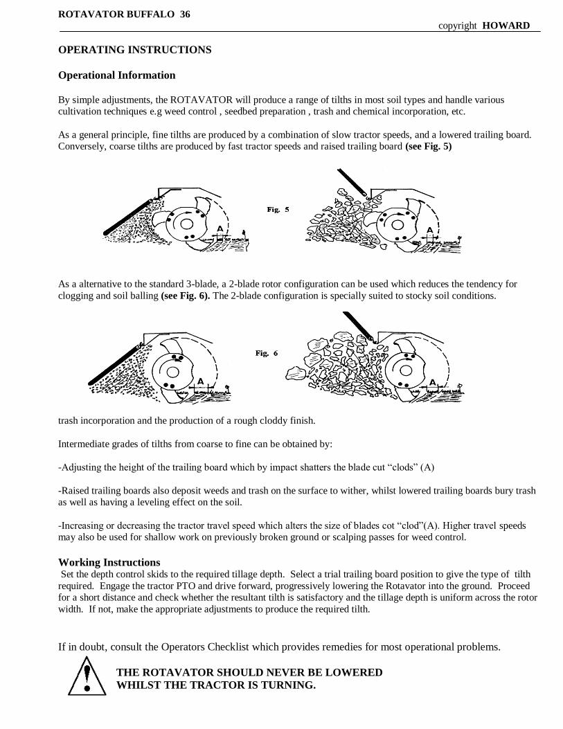
By simple adjustments, the ROTAVATOR will produce a range of tilths in most soil types and handle various cultivation techniques e.g weed control , seedbed preparation , trash and chemical incorporation, etc.
As a general principle, fine tilths are produced by a combination of slow tractor speeds, and a lowered trailing board. Conversely, coarse tilths are produced by fast tractor speeds and raised trailing board (see Fig. 5)
As a alternative to the standard 3-blade, a 2-blade rotor configuration can be used which reduces the tendency for
clogging and soil balling (see Fig. 6). The 2-blade configuration is specially suited to stocky soil conditions.
trash incorporation and the production of a rough cloddy finish.
Intermediate grades of tilths from coarse to fine can be obtained by:
-Adjusting the height of the trailing board which by impact shatters the blade cut “clods” (A)
-Raised trailing boards also deposit weeds and trash on the surface to wither, whilst lowered trailing boards bury trash as well as having a leveling effect on the soil.
-Increasing or decreasing the tractor travel speed which alters the size of blades cot “clod”(A). Higher travel speeds may also be used for shallow work on previously broken ground or scalping passes for weed control.
Working Instructions Set the depth control skids to the required tillage depth. Select a trial trailing board position to give the type of tilth
required. Engage the tractor PTO and drive forward, progressively lowering the Rotavator into the ground. Proceed for a short distance and check whether the resultant tilth is satisfactory and the tillage depth is uniform across the rotor
width. If not, make the appropriate adjustments to produce the required tilth.
If in doubt, consult the Operators Checklist which provides remedies for most operational problems.
THE ROTAVATOR SHOULD NEVER BE LOWERED
WHILST THE TRACTOR IS TURNING.
Excessive Blade Wear.
- Reduce rotor speed
- Replace loose or bent blades
Excessive Blade Wear. - obstacles entangled in blades
- Blades incorrectly mounted with no
scroll effects or blades fitted with
blunt edge leading
- Broken, bent or missing blades
- Bent rotor
Obvious Points. - ROTAVATOR not level – cutting too
deep on right side. Shorten right hand
tractor lift rod or adjust depth control
skid.
- No overlapping – drive closer to last
run.
- Working on hillsides – Work up the
slope if possible. If lateral work from
the top to bottom in order to limit any
terracing effect.
Rotavating. - when operating the Rotavator, the
most suitable practise is to work in
“lands”.
- The ROTAVATED ground should
always be to the right of the driver.
- ROTAVATING the field headlands
should not be carried out until the
“lands” have been completed.
- Always raise the Rotavator before
turning.
D
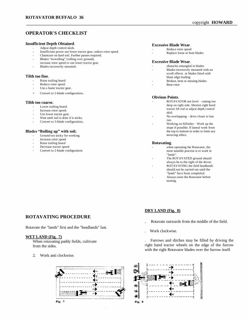
DRY LAND (Fig. 8)
1
. Rotavate outwards from the middle of the field.
2
. Work clockwise.
3
. Furrows and ditches may be filled by driving the
right hand tractor wheels on the edge of the furrow
with the right Rotavator blades over the furrow itself.
ROTAVATOR BUFFALO 36
copyright HOWARD
OPERATOR'S CHECKLIST Insufficient Depth Obtained.
- Adjust depth control skids.
- Insufficient power use lower tractor gear, reduce rotor speed.
- Chaincase on hard soil. Further passes required.
- Blades “trowelling” (rolling over ground),
increase rotor speed or use lower tractor gear.
- Blades incorrectly mounted.
Tilth too fine.
- Raise trailing board
- Reduce rotor speed.
- Use a faster tractor gear.
- Convert to 2-blade configuration.
Tilth too coarse. - Lower trailing board.
- Increase rotor speed.
- Use lower tractor gear.
- Wait until soil is drier if it sticks.
- Convert to 3-blade configuration..
Blades “Balling up” with soil. - Ground too sticky for working.
- Increase rotor speed
- Raise trailing board
- Decrease tractor speed
- Convert to 2-blade configuration
ROTAVATING PROCEDURE
Rotavate the "lands" first and the "headlands" last.
WET LAND (Fig. 7)
When rotavating paddy fields, cultivate
from the sides.
2. Work anti clockwise.
ROTAVATOR BUFFALO 36
copyright HOWARD
Always drive with rotavated ground ON THE RIGHT, except when finishing the headlands, which should be started against the
bund/fence - and worked anti clockwise.
AFTER COMPLETING A PASS, ALWAYS RAISE THE ROTAVATOR BEFORE TURNING.
SOIL
The amount of clay present in heavier soils gives them cohesion. Tilth in light soils will tend to be finer, whereas a greater variety of tilth - coarse, medium, fine - is obtainable in heavier soils.
The farmer will easily recognise when the soil is in a suitable condition for tillage, and will be able to determine the best choice of
tilth based on the flexible options available in rotavation, i.e. blade type and configuration, position of trailing board, rotor speed
and tractor travel speed.
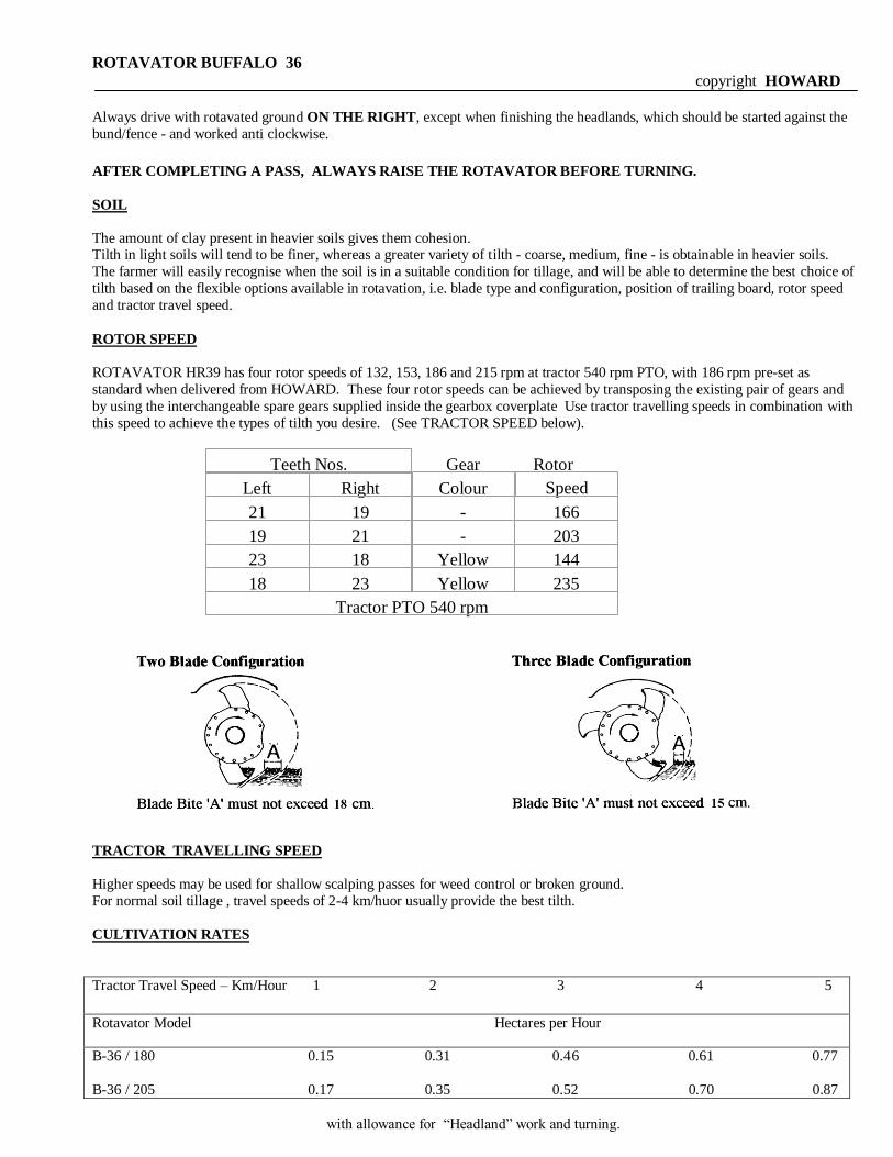
ROTOR SPEED
ROTAVATOR HR39 has four rotor speeds of 132, 153, 186 and 215 rpm at tractor 540 rpm PTO, with 186 rpm pre-set as
standard when delivered from HOWARD. These four rotor speeds can be achieved by transposing the existing pair of gears and
by using the interchangeable spare gears supplied inside the gearbox coverplate Use tractor travelling speeds in combination with
this speed to achieve the types of tilth you desire. (See TRACTOR SPEED below).
TRACTOR TRAVELLING SPEED
Higher speeds may be used for shallow scalping passes for weed control or broken ground.
For normal soil tillage , travel speeds of 2-4 km/huor usually provide the best tilth.
CULTIVATION RATES
Tractor Travel Speed – Km/Hour 1 2 3 4 5
Rotavator Model Hectares per Hour
B-36 / 180 0.15 0.31 0.46 0.61 0.77
B-36 / 205 0.17 0.35 0.52 0.70 0.87
with allowance for “Headland” work and turning.
Gear
Rotor
Teeth Nos.
Left
Right
Colour
21
19
-
166
19
21
-
203
23
18
Yellow
144
18
23
Yellow
235
Tractor PTO 540 rpm
Speed

Fig. 24
Fig. 25
ROTAVATOR BUFFALO 36
copyright HOWARD
Clutch Maintenance
Daily or every 8 hours worked, check and adjust Weekly or every 50 hours worked,
Slip Clutch. inspect/replace worn clutch friction discs.
Clutch Setting / Adjusment
To adjust the clutch, turn the eight nuts until they just touch the springs. Then tighten the nuts evenly and diametrically with a
spanner:
Method No. 1
until you achieve 2 turns on each nut;
(see Fig. 24)
Method No. 2
until the springs are compressed to 30 mm;
(see Fig. 25)
NEVER under any circumstances, tighten the 8 tension springs of the clutch to
coil bound for soil preparation as this shall adversely affect the transmission system.
Local working conditions may necessitate some further adjustments of the nuts. If so, the adjustment should be even, the same
amount being given to each nut.
In normal operation, the temperature of the clutch should be no higher than the temperature of the gearbox. However, if the clutch
becomes hotter than the gearbox, this will indicate the clutch needs tightening.
If set too loosely, the clutch plates slip excessively, generating considerable frictional heat. In addition to causing the clutch plates
to quickly wear out, to loose a clutch setting wiil result in erratic turning of the rotor and irregular work.
It is, therefore , important to check that the clutch is correctly adjusted.
30 mm
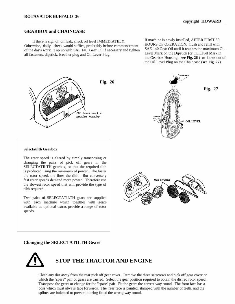
Fig. 26
If machine is newly installed, AFTER FIRST 50
HOURS OF OPERATION, flush and refill with
SAE 140 Gear Oil until it reaches the maximum Oil
Level Mark on the Dipstick (or Oil Level Mark in
the Gearbox Housing - see Fig. 26 ) or flows out of
the Oil Level Plug on the Chaincase (see Fig. 27).
Fig. 27
Clean any dirt away from the rear pick off gear cover. Remove the three setscrews and pick off gear cover on
which the "spare" pair of gears are carried. Select the gear position required to obtain the disired rotor speed.
Transpose the gears or change for the "spare" pair. Fit the gears the correct way round. The front face has a
boss which must always face forwards. The rear face is painted, stamped with the number of teeth, and the
splines are indented to prevent it being fitted the wrong way round.
ROTAVATOR BUFFALO 36
copyright HOWARD
GEARBOX and CHAINCASE
If there is sign of oil leak, check oil level IMMEDIATELY.
Otherwise, daily check would suffice, preferably before commencement of the day's work. Top up with SAE 140 Gear Oil if necessary and tighten
all fasteners, dipstick, breather plug and Oil Lever Plug.
STOP THE TRACTOR AND ENGINE
Selectatilth Gearbox
The rotor speed is altered by simply transposing or
changing the pairs of pick off gears in the SELECTATILTH gearbox, so that the required tilth
is produced using the minimum of power. The faster
the rotor speed, the finer the tilth. But conversely
fast rotor speeds demand more power. Therefore use
the slowest rotor speed that will provide the type of
tilth required.
Two pairs of SELECTATILTH gears are supplied
with each machine which together with gears
available as optional extras provide a range of rotor
speeds.
Changing the SELECTATILTH Gears

ROTAVATOR BUFFALO 36
copyright HOWARD
DO NOT MIX COLOUR
Fit the pair of gears not in use on the pick off gear cover. DO NOT USE THE ROTAVATOR WITHOUT THE SPARE PAIR OF
GEARS FITTED. This stops the rotating pair of gears from damaging the pick off gear cover. The gasket must be in place and
effective.
Chaincase
After every 500 hours, the chaincase should be
thoroughtly cleaned out. With the Depth Control
wheel and ground skid remove (if they are fitted),
slacken the chain adjusting screw, then unscrew all
the bolts securing chaincase to backplate allowing the
chaincase oil to drain out from the joint. Remove the
cover, ensuring that gasket is not damaged, and wash
out the inside of the chaincase and the chain,with kerosene. Reassemble and fill with SEA140 gear oil
through the top plug in the chaincase until oil flows out
of the Oil Level Plug at the bottom of the chaincase.
Drive Chain
Correct tension of the drive chain is as important as
Proper lubrication. To check chain tension, remove the
inspection plug on the rear side of the chaincase and
check the movement of the chain, using a screwdriver or
a piece of hooked wire. The total back and forward
movement should be approximately 13 mm-19 mm.
If the chain needs tightening, unscrew the locknut on the
chain adjusting screw on the leading edge of the
chaincase, and screw up the adjuster until the required
tension is obtained. Retighten the lock nut.
ROTOR DRIVE SHAFT / STUB AXLE
Daily check for oil leakage in these two areas. If oil leaks, take IMMEDIATE action to clean the “wedged”
seals of all foreign materials, replace worn seal kits and / or bearings. Loose nut holding the Rotor Drive Shaft or Stub Axle and
blocked breather in the Jackshaft Housing may also be a cause to this problem.
ROTAVATOR BUFFALO 36
copyright HOWARD
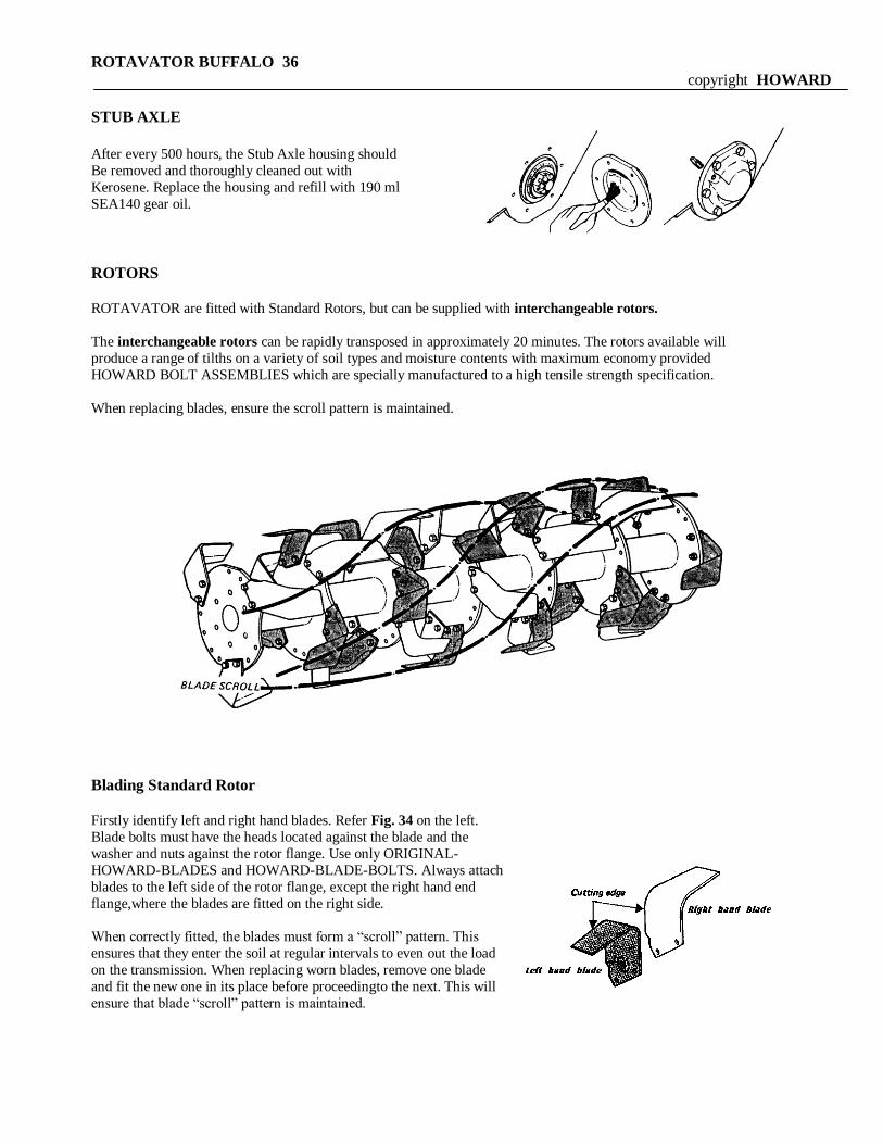
STUB AXLE
After every 500 hours, the Stub Axle housing should
Be removed and thoroughly cleaned out with
Kerosene. Replace the housing and refill with 190 ml
SEA140 gear oil.
ROTORS
ROTAVATOR are fitted with Standard Rotors, but can be supplied with interchangeable rotors.
The interchangeable rotors can be rapidly transposed in approximately 20 minutes. The rotors available will
produce a range of tilths on a variety of soil types and moisture contents with maximum economy provided
HOWARD BOLT ASSEMBLIES which are specially manufactured to a high tensile strength specification.
When replacing blades, ensure the scroll pattern is maintained.
Blading Standard Rotor
Firstly identify left and right hand blades. Refer Fig. 34 on the left.
Blade bolts must have the heads located against the blade and the
washer and nuts against the rotor flange. Use only ORIGINAL-
HOWARD-BLADES and HOWARD-BLADE-BOLTS. Always attach
blades to the left side of the rotor flange, except the right hand end
flange,where the blades are fitted on the right side.
When correctly fitted, the blades must form a “scroll” pattern. This
ensures that they enter the soil at regular intervals to even out the load
on the transmission. When replacing worn blades, remove one blade
and fit the new one in its place before proceedingto the next. This will
ensure that blade “scroll” pattern is maintained.
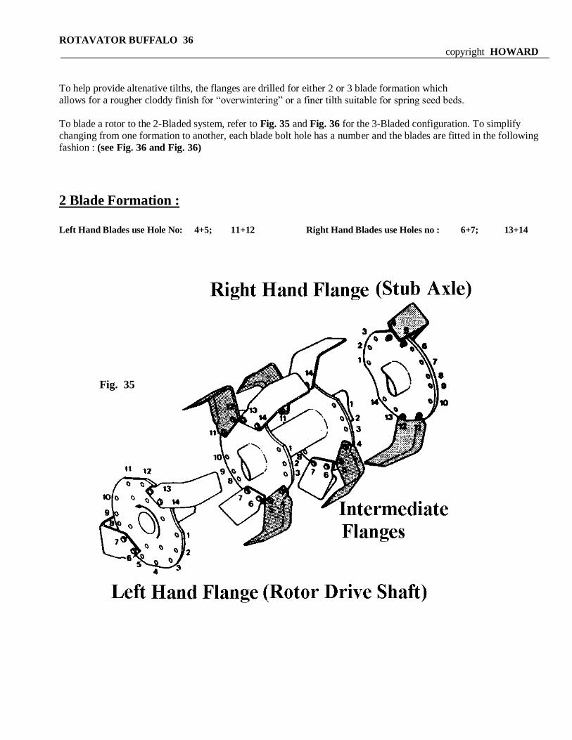
Fig. 35
ROTAVATOR BUFFALO 36
copyright HOWARD
To help provide altenative tilths, the flanges are drilled for either 2 or 3 blade formation which
allows for a rougher cloddy finish for “overwintering” or a finer tilth suitable for spring seed beds.
To blade a rotor to the 2-Bladed system, refer to Fig. 35 and Fig. 36 for the 3-Bladed configuration. To simplify
changing from one formation to another, each blade bolt hole has a number and the blades are fitted in the following
fashion : (see Fig. 36 and Fig. 36)
2 Blade Formation :
Left Hand Blades use Hole No: 4+5; 11+12 Right Hand Blades use Holes no : 6+7; 13+14
Left Hand Blades use
Hole No: 1 + 2; 7 + 8; 11 + 12
Right Hand Blades use
Hole No: 3 + 4; 9 + 10; 13 + 14
ROTAVATOR BUFFALO 36
copyright HOWARD
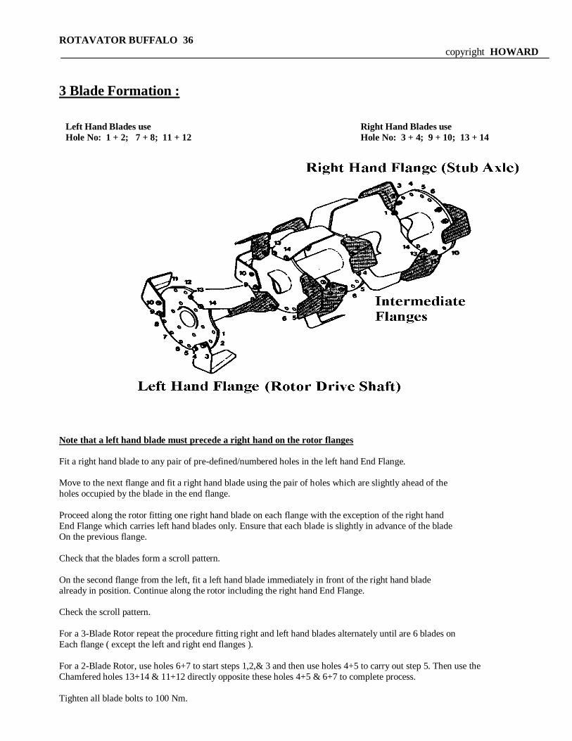
3 Blade Formation :
Note that a left hand blade must precede a right hand on the rotor flanges
Fit a right hand blade to any pair of pre-defined/numbered holes in the left hand End Flange.
Move to the next flange and fit a right hand blade using the pair of holes which are slightly ahead of the
holes occupied by the blade in the end flange.
Proceed along the rotor fitting one right hand blade on each flange with the exception of the right hand
End Flange which carries left hand blades only. Ensure that each blade is slightly in advance of the blade
On the previous flange.
Check that the blades form a scroll pattern.
On the second flange from the left, fit a left hand blade immediately in front of the right hand blade
already in position. Continue along the rotor including the right hand End Flange.
Check the scroll pattern.
For a 3-Blade Rotor repeat the procedure fitting right and left hand blades alternately until are 6 blades on
Each flange ( except the left and right end flanges ).
For a 2-Blade Rotor, use holes 6+7 to start steps 1,2,& 3 and then use holes 4+5 to carry out step 5. Then use the
Chamfered holes 13+14 & 11+12 directly opposite these holes 4+5 & 6+7 to complete process.
Tighten all blade bolts to 100 Nm.
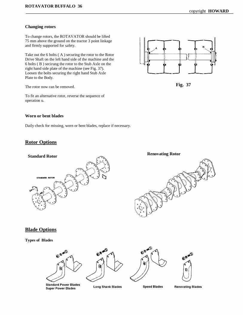
Fig. 37
Standard Rotor Renovating Rotor
ROTAVATOR BUFFALO 36 copyright HOWARD
Changing rotors
To change rotors, the ROTAVATOR should be lifted 75 mm above the ground on the tractor 3 point linkage
and firmly supported for safety.
Take out the 6 bolts ( A ) securing the rotor to the Rotor
Drive Shaft on the left hand side of the machine and the
6 bolts ( B ) secirung the rotor to the Stub Axle on the
right hand side plate of the machine (see Fig. 37).
Loosen the bolts securing the right hand Stub Axle
Plate to the Body.
The rotor now can be removed.
To fit an alternative rotor, reverse the sequence of
operation u.
Worn or bent blades
Daily check for missing, worn or bent blades, replace if necessary.
Rotor Options
Blade Options Types of Blades
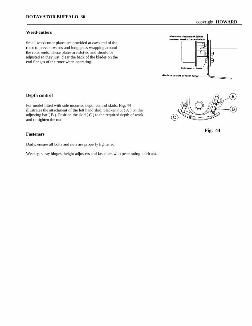
Fig. 44
ROTAVATOR BUFFALO 36
copyright HOWARD
Weed-cutters
Small weedcutter plates are provided at each end of the
rotor to prevent weeds and long grass wrapping around
the rotor ends. These plates are slotted and should be
adjusted so they just clear the back of the blades on the
end flanges of the rotor when operating.
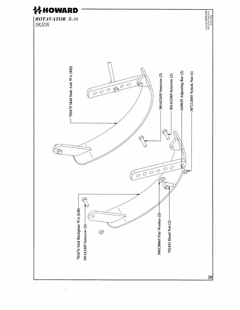
Depth control
For model fitted with side mounted depth control skids: Fig. 44
illustrates the attachment of the left hand skid. Slacken nut ( A ) on the adjusting bar ( B ). Position the skid ( C ) to the required depth of work
and re-tighten the nut.
Fasteners
Daily, ensure all bolts and nuts are properly tightened.
Weekly, spray hinges, height adjusters and fasteners with penetrating lubricant.
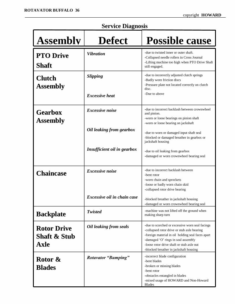
Possible cause Defect Assembly
-incorrect blade configuration
-bent blades
-broken or missing blades
-bent rotor
-obstacles entangled in blades
-mixed usage of HOWARD and Non-Howard
Blades
Rotavator “Bumping” RRoottoorr &&
BBllaaddeess
-due to scorched or excessive worn seal facings
-collapsed rotor drive or stub axle bearing
-foreign material in oil holding seal faces apart
-damaged „O‟ rings in seal assembly
-loose rotor drive shaft or stub axle nut
-blocked breather in jackshaft housing
Oil leaking from seals RRoottoorr DDrriivvee
SShhaafftt && SSttuubb
AAxxllee
-machine was not lifted off the ground when
making sharp turn Twisted
BBaacckkppllaattee
-due to incorrect backlash between
-bent rotor
-worn chain and sprockets
-loose or badly worn chain skid
-collapsed rotor drive bearing
-blocked breather in jackshaft housing
-damaged or worn crownwheel bearing seal
Excessive noise
Excessive oil in chain case
CChhaaiinnccaassee
-due to incorrect backlash between crownwheel
and pinion.
-worn or loose bearings on pinion shaft
-worn or loose bearing on jackshaft
-due to worn or damaged input shaft seal
-blocked or damaged breather in gearbox or
jackshaft housing
-due to oil leaking from gearbox
-damaged or worn crownwheel bearing seal
Excessive noise
Oil leaking from gearbox
Insufficient oil in gearbox
GGeeaarrbbooxx
AAsssseemmbbllyy
-due to incorrectly adjusted clutch springs
-Badly worn friction discs
-Pressure plate not located correctly on clutch disc.
-Due to above
Slipping
Excessive heat
CClluuttcchh
AAsssseemmbbllyy
-due to twisted inner or outer shaft.
-Collapsed needle rollers in Cross Journal
-Lifting machine too high when PTO Drive Shaft
still engaged.
Vibration PPTTOO DDrriivvee
SShhaafftt
ROTAVATOR BUFFALO 36
copyright HOWARD
Service Diagnosis
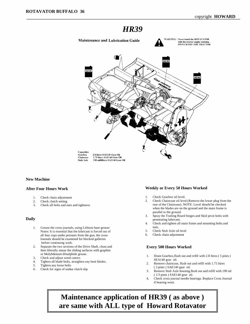
Weekly or Every 50 Hours Worked
1. Check Gearbox oil level.
2. Check Chaincase oil level.(Remove the lower plug from the
rear of the Chaincase). NOTE: Level should be checked
when the blades are on the ground and the main frame is
parallel to the ground.
3. Spray the Trailing Board hinges and Skid pivot bolts with
penetrating lubricant.
4. Check and tighten all main frame and mounting bolts and
nuts.
5. Check Stub Axle oil level
6. Check chain adjustment
Every 500 Hours Worked
1. Drain Gearbox,flush out and refill with 2.8 litres ( 5 pints )
SEA140 gear oil.
2. Remove chaincase, flush out and refill with 1.75 litres
( 3 pints ) SAE140 gear oil.
3. Remove Stub Axle housing,flush out and refill with 190 ml
( 1/3 pints ) SAE140 gear oil.
4. Check cross journal needle bearings. Replace Cross Journal
if bearing worn.
ROTAVATOR BUFFALO 36
copyright HOWARD
HR39
New Machine
After Four Hours Work
1. Check chain adjustment
2. Check clutch setting
3. Check all bolts and nuts and tightness
Daily
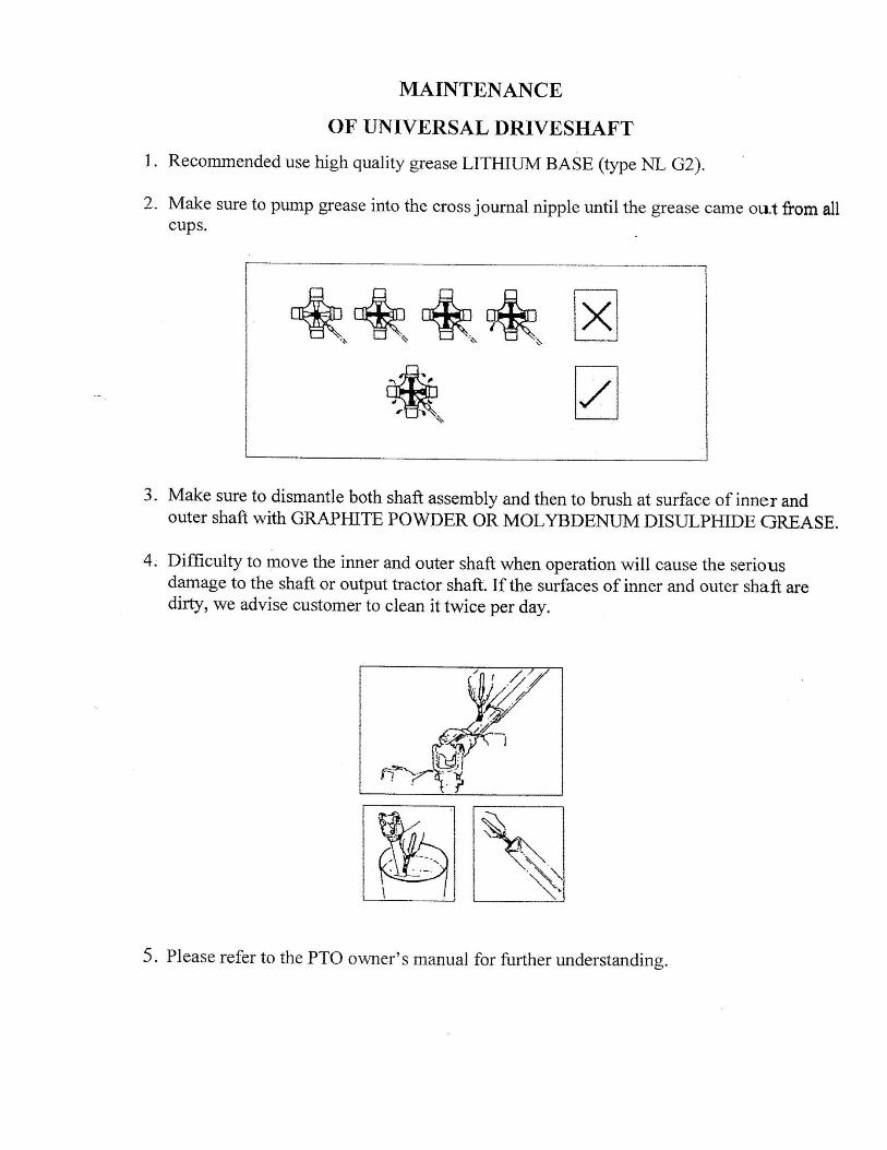
1. Grease the cross journals, using Lithium base grease:
Notes: It is essential that the lubricant is forced out of
all four cups under pressure from the gun, the cross
lournals should be examined for blocked galleries
before continuing work.
2. Separate the two sections of the Drive Shaft, clean and
then liberally smear the sliding surfaces with graphite
or Molybdenum-Disulphide grease.
3. Check and adjust weed cutters
4. Tighten all blade bolts, straighten any bent blades.
5. Tighten any loose bolts
6. Check for signs of undue clutch slip
Maintenance application of HR39 ( as above )
are same with ALL type of Howard Rotavator