rotationally extruding 3d objects from 2d objectsfiles.openscad.org/tutorial/chapter_8.pdf ·...
TRANSCRIPT

Chapter 8
Rotationally extruding 3D objects from 2D objects
So far you have been creating a lot of models and customizing your car designs while developing
solid parametric modelling skills and exploring different features of OpenSCAD. It’s quite
impressive to notice for a moment that every model that you have so far created makes use of
just 3 primitives. The sphere, the cube and the cylinder. By combining these primitives with the
help of the transformation commands you can create a plethora of models. There are still
models though that you can’t create just by using these 3 primitives. One such example is the
following wheel design.
The above wheel design requires the creation of an object that looks like a donut.

This donut shaped object can’t be created with the use of the sphere, cube and cylinder
primitives. Instead it requires the use of 2D primitives and a new command which can create 3D
shapes from 2D profiles. Specifically, the donut can be created by first defining a circular 2D
profile using the circle primitive and then rotationally extruding this profile using the
rotate_extrude command.
$fa = 1;
$fs = 0.4;
wheel_radius = 12;
tyre_diameter = 6;
translate([wheel_radius - tyre_diameter/2, 0])circle(d=tyre_diameter);

$fa = 1;
$fs = 0.4;
wheel_radius = 12;
tyre_diameter = 6;
rotate_extrude(angle=360) {
translate([wheel_radius - tyre_diameter/2, 0])circle(d=tyre_diameter);
}

There are a few things you should notice about the creation of the 2D profile. The 2D profile in
this case is just circle object. The to be rotationally extruded 2D profile should lie on the half
plane where the positive X axis belongs. The circle command is one of OpenSCAD’s available 2D
primitives. The size of the circle is defined by specifying its diameter which is set equal to a
variable named tyre_diameter, since the donut-shaped object corresponds to the tyre of the
wheel. Aside from the circle primitive there is another available 2D primitive, the square
primitive. 2D primitive objects are always created on the XY plane and are considered to have
zero thickness. Thus, 2D primitives are not used directly as a part of a model, but indirectly to
define 2D profiles on which the rotate_extrude and linear_extrude commands can be applied to
form 3D objects.
You should notice a few things about the use of the rotate_extrude command. The rotate
extrude command is used to create 3D objects and always requires as an input a 2D profile. The
commands that create the desired 2D profile need to be placed inside the pair of curly brackets
that follows the rotate_extrude command. The 3D object that is created by the rotate_extrude
command is the result of rotating the 2D profile around the Y axis. The resulting 3D object
though is positioned in such a way as if the Y axis was rotated in the place of the Z axis. This is
the only confusing part about using the rotate_extrude command that you should be aware of.
Although the rotate_extrude command produces a 3D object that is the result of rotating the
supplied 2D profile around the Y axis, the final product that you get is this object rotated 90
degrees around the X axis so that the Y axis has been rotated up to the Z axis.
To state the previous more clearly, the rotate_extrude command takes a 2D profile as an input.
Then it creates a 3D object which is the result of rotating the supplied 2D profile around the Y
axis.

But the 3D model it actually produces is rotated by 90 degrees around the X axis.
The rotate_extrude command has one input parameter named angle. The angle parameter is
used to define how many degrees the 2D profile will be rotated around the Y axis. In this case
the angle parameter is set equal to 360 degrees which corresponds to a full circle.
Setting the angle parameter equal to 60 degrees would create the following model.
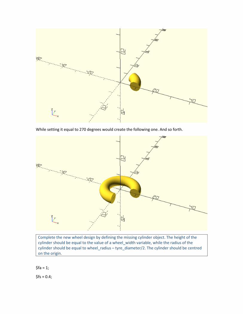
While setting it equal to 270 degrees would create the following one. And so forth.
Complete the new wheel design by defining the missing cylinder object. The height of the cylinder should be equal to the value of a wheel_width variable, while the radius of the cylinder should be equal to wheel_radius – tyre_diameter/2. The cylinder should be centred on the origin.
$fa = 1;
$fs = 0.4;

wheel_radius = 12;
wheel_width = 4;
tyre_diameter = 6;
rotate_extrude(angle=360) {
translate([wheel_radius-tyre_diameter/2,0])circle(d=tyre_diameter);
}
cylinder(h=wheel_width, r=wheel_radius - tyre_diameter/2, center=true);
To make this wheel compatible with the models from the previous chapters rotate it by 90 degrees around the X axis. Turn this wheel design into a module named rounded_simple_wheel and add it on your vehicle_parts.scad script for later use.
…
module rounded_simple_wheel(wheel_radius=12, wheel_width=4, tyre_diameter=6) {
rotate([90,0,0]) {
rotate_extrude(angle=360) {
translate([wheel_radius-tyre_diameter/2,0])circle(d=tyre_diameter);
}
cylinder(h=wheel_width, r=wheel_radius - tyre_diameter/2, center=true);
}

}
…
The above wheel is an axisymmetric object, which means it exhibits symmetry around an axis. Specifically, the axis of symmetry is the axis around which the 2D profile was rotated to form the 3D object. When an object is axisymmetric it can be created with just one rotate_extrude command as long as the appropriate 2D profile is supplied. This is not the case with the above wheel design as the center part was added with a cylinder command separate from the rotational extrusion. Remove the cylinder command from the above module and make appropriate additions on the supplied 2D profile so that the whole wheel is created by the rotate_extrude command.

…
translate([wheel_radius-tyre_diameter/2,0])circle(d=tyre_diameter);
translate([0,-wheel_width/2])square([wheel_radius-tyre_diameter/2,wheel_width]);
…
…
module rounded_simple_wheel(wheel_radius=12, wheel_width=4, tyre_diameter=6) {

rotate([90,0,0]) {
rotate_extrude(angle=360) {
translate([wheel_radius-tyre_diameter/2,0])circle(d=tyre_diameter);
translate([0,-wheel_width/2])square([wheel_radius-tyre_diameter/2,wheel_width]);
}
}
}
…
You should remember that axisymmetric objects can be completely created out of a
rotate_extrude command. The previous wheel design is a concreate example of this. Whether
you decide to create an axisymmetric object by suppling the 2D profile of the whole object and
by using a single rotate_extrude or by using a rotate_extrude command only for its parts that
can’t be created in any other way, depends on each case and is up to you. If you wanted for
example to further modularize your wheel designs and separate them into combinable tire and
rim modules, you would inevitably need to create the donut-shaped tire using a rotate_extrude
command. Since in this case the rim of the wheel would be a separate module without a
rotate_extrude command already present in it, the simplest and most straight forward way to
create it would be by using a cylinder command.
Challenge
It’s time to put your new knowledge into practice to create a rim for a mini robot car project.
Extend the rounded_simple_wheel module, so that the wheel design has a hole on its hub that can be used for mounting it on an axle. To do so you would need to subtract a cylinder from the existing model using a difference command. The diameter of the hole should be equal to a new module input parameter named axle_diameter. The default value of this parameter should be 3 units. By the way in which you define the height of the cylinder you should guarantee that the cylinder is always a bit longer than the width of the wheel to avoid any errors when using the difference command. After saving the modified module you should use it to create a version a wheel with wheel_radius, wheel_width, tire_diameter and axle_diameter of 20, 6, 4 and 5 units respectively.

…
module rounded_simple_wheel(wheel_radius=12, wheel_width=4, tyre_diameter=6,
axle_diameter=3) {
difference() {
// wheel
rotate([90,0,0]) {
rotate_extrude(angle=360) {
translate([wheel_radius-tyre_diameter/2,0])circle(d=tyre_diameter);
translate([0,-wheel_width/2])square([wheel_radius-tyre_diameter/2,wheel_width]);
}
}
// axle hole
rotate([90,0,0])cylinder(h=wheel_width+1,r=axle_diameter/2,center=true);
}
}

…
…
rounded_simple_wheel(wheel_radius=20, wheel_width=6, tyre_diameter=4, axle_diameter=5);
…
This wheel design looks about right for a mini robot car application, but you could do something
to give more traction to your robot. Instead of 3D printing the whole wheel, you could just 3D
print the rim and then add an O-ring or rubber band as the tire for more traction. The resulting
wheel would look like the following image, where the O-ring or rubber band is represented by
the blue color.
The corresponding rim that you would have to 3D print in this case is the following.

Using the rounded_simple_wheel module as a guide, create a new module named robot_rim. The robot_rim module should have the same input parameters as the rounded_simple_wheel module. Add all necessary commands to the robot_rim module so that it creates the above rim design. There are two way you in which can do this. *The first way is to subtract the circle that corresponds to the tire from the square that corresponds to the rim in the definition of the design’s 2D profile inside the rotate_extrude command and then to additionally subtract the axle’s cylinder from the resulting 3D object to get the final rim design. *The second way is to subtract a donut-shaped object that corresponds to the tire and the cylinder that corresponds to the axle hole from the larger cylinder that corresponds to the rim. Remember that there is no right or wrong choice and in practice you would most likely go with the option that came first on your head or made more sense to you. But since you are just developing your design intuition you should try both ways and see which one you like the most.
*First approach
…
module rounded_simple_wheel(wheel_radius=12, wheel_width=4, tyre_diameter=6,
axle_diameter=3) {
rotate([90,0,0])difference() {
// resulting rim

rotate_extrude(angle=360) {
difference() {
// cylindrical rim prodile
translate([0,-wheel_width/2])square([wheel_radius-tyre_diameter/2,wheel_width]);
// tire profile
translate([wheel_radius-tyre_diameter/2,0])circle(d=tyre_diameter);
}
}
// axle hole
cylinder(h=wheel_width+1,r=axle_diameter/2,center=true);
}
}
…
*Second approach

…
module rounded_simple_wheel(wheel_radius=12, wheel_width=4, tyre_diameter=6,
axle_diameter=3) {
rotate([90,0,0])difference() {
// cylindrical rim
cylinder(h=wheel_width,r=wheel_radius-tyre_diameter/2,center=true);
// tire
rotate_extrude(angle=360) {
translate([wheel_radius-tyre_diameter/2,0])circle(d=tyre_diameter);
}
// axle hole
cylinder(h=wheel_width+1,r=axle_diameter/2,center=true);
}
}
…

If you weren’t 3D printing this rim but instead manufacturing it, the second approach would be
more appropriate. This is because it would force you to think of your design as starting from a
solid piece of metal and then taking its final shape by consecutive manufacturing processes that
remove material from it.
Linearly extruding 3D objects from 2D objects
As briefly mentioned, there is another OpenSCAD command that can be used to create 3D
objects from supplied 2D profiles. This is the linear_extrude command. In contrast to the
rotate_extrude command, linear_extrude creates 3D object by extending along the Z axis a 2D
profile that lies on the XY plane. Similar to the rotate_extrude command, linear_extrude can be
used when the 3D object you want to create can’t be directly created by combining available 3D
primitives. On such example is the following.
$fa = 1;
$fs = 0.4;
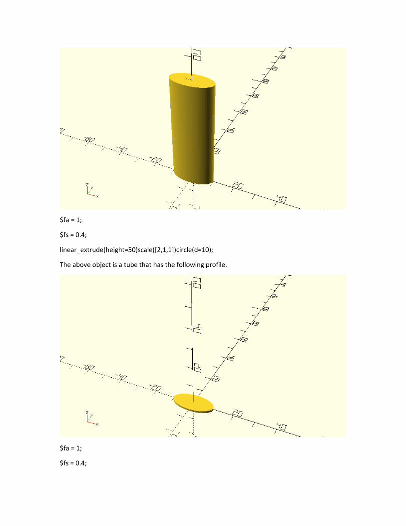
linear_extrude(height=50)scale([2,1,1])circle(d=10);
The above object is a tube that has the following profile.
$fa = 1;
$fs = 0.4;
scale([2,1,1])circle(d=10);
There are a few points you should notice regarding the use of linear_extrude. The syntax of
linear_extrude is similar to the syntax of the rotate_extrude command. The commands that
create the 2D profile that will be extruded along the Z axis need to be placed inside a pair of
curly brackets that follows the linear_extrude command. The parameter height is used to define
how many units along the Z axis the 2D profile is going to be extruded. By default, the 2D profile
is extruded along the positive direction of the Z axis by an amount of units equal to the value
assigned to the height parameter.
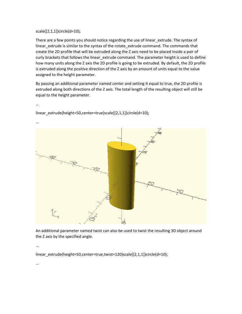
By passing an additional parameter named center and setting it equal to true, the 2D profile is
extruded along both directions of the Z axis. The total length of the resulting object will still be
equal to the height parameter.
…
linear_extrude(height=50,center=true)scale([2,1,1])circle(d=10);
…
An additional parameter named twist can also be used to twist the resulting 3D object around
the Z axis by the specified angle.
…
linear_extrude(height=50,center=true,twist=120)scale([2,1,1])circle(d=10);
…

Finally, another parameter named scale can be used to scale one end of the resulting 3D by the
specified scaling factor.
…
linear_extrude(height=50,center=true,twist=120,scale=1.5)scale([2,1,1])circle(d=10);
…
It should be pretty clear by now how the rotate_extrude and linear_extrude commands give you
the ability to create objects that wouldn’t be possible by directly combining the available 3D

primitives. You can use these commands to create more abstract and artistic designs but let’s
see how you could use the linear_extrude command to create a new car body.
Use the linear_extrude command similar to the above examples in order to create the following car body. You should create a new module named extruded_car_body. The module should have a length, rear_height, rear_width and scaling_factor input parameter. The default values of the parameters should be 80, 20, 25 and 0.5 units respectively. The length and scaling factor parameters of the module will be used in the call to linear_extrude command to set the values of its height and scale parameters. The supplied 2D profile should be a circle that has been resized according to the rear_height and rear_width parameters.
module rounded_car_body(length=80, rear_height=20, rear_width=25, scaling_factor=0.5) {
rotate([0,-
90,0])linear_extrude(height=length,center=true,scale=scaling_factor)resize([rear_height,rear_wi
dth])circle(d=rear_height);
}
Extend the previous module by adding a boolean input parameter named rounded. The default value of the parameter should be false. If the rounded parameter is set to true, then two additional objects should be created at the front and rear of the body in order to make in rounded as in the following image. These two objects are spheres that have been resized and scaled. Try figuring out an appropriate way to resize and scale the sphere to achieve a result similar to the image below.
…
rounded_car_body(rounded=true);

…
…
module rounded_car_body(length=80, rear_height=20, rear_width=25, scaling_factor=0.5,
rounded=false) {
// center part
rotate([0,-
90,0])linear_extrude(height=length,center=true,scale=scaling_factor)resize([rear_height,rear_wi
dth])circle(d=rear_height);
if (rounded) {
// rear part
translate([length/2,0,0])resize([rear_height,rear_width,rear_height])sphere(d=rear_height);
// front part
translate([-
length/2,0,0])scale(scaling_factor)resize([rear_height,rear_width,rear_height])sphere(d=rear_h
eight);
}

}
…
Use the new rounded body in any car design that you like.
As mentioned, the rotate_extrude and linear_extrude commands can also be used to create
more abstract objects. When the supplied 2D profile is created using the available circle and
square 2D primitives and when the twist and scale parameters of the linear_extrude command
are not utilized, then the resulting 3D object could also be directly created using the available 3D
primitives. What really makes the use of these commands much more powerful is the ability to
create any 2D profile that is not a combination of circles and squares but rather an arbitrary
shape. This ability is available through the use of the polygon 2D primitive which and you are
going to learn about in the next chapter.