rotary sieve 360 + hopperemanuals.nordson.com/finishing/files/stockport/7580607_01.pdf · upon...
TRANSCRIPT

Rotary Sieve 360 + Hopper
Customer Product ManualPart 7580607_01
Issued 09/19
NORDSON Deutschland GmbH
For parts and technical support, call the Industrial CoatingSystems Customer Support Center at (800) 433‐9319 or
contact your local Nordson representative.
This document is subject to change without notice.Check http://emanuals.nordson.com for the latest version.

Part 7580607_01 � 2019 Nordson Corporation
Contact Us
Nordson Corporation welcomes requests for information, comments, andinquiries about its products. General information about Nordson can befound on the Internet using the following address:http://www.nordson.com.
Address all correspondence to:
Nordson Deutschland GmbHHeinrich Hertz Strasse 4240699 Erkrath,Germany
Notice
This is a Nordson Corporation publication which is protected by copyright.Original copyright date 2018. No�part�of�this�document may bephotocopied, reproduced, or translated to another language without theprior written consent of Nordson�Corporation. The�information�containedin this publication is subject to change without notice.
Trademarks
Encore, HDLV, Spectrum, Nordson and the Nordson logo are registeredtrademarks of Nordson Corporation.
All other trademarks are the property of their respective owners.

Change Record i
Part 7580607_01� 2019 Nordson Corporation
Change RecordRevision Date Change

Change Recordii
Part 7580607_01 � 2019 Nordson Corporation

Table of Contents
Part 7580607_01� 2019 Nordson Corporation
Table of Contents
Safety 1. . . . . . . . . . . . . . . . . . . . . . . . . . . . . . . . . . . . . . . . . . . . . . . . . .Qualified Personnel 1. . . . . . . . . . . . . . . . . . . . . . . . . . . . . . . . . . . .Intended Use 1. . . . . . . . . . . . . . . . . . . . . . . . . . . . . . . . . . . . . . . . . .Regulations and Approvals 1. . . . . . . . . . . . . . . . . . . . . . . . . . . . . .Personal Safety 2. . . . . . . . . . . . . . . . . . . . . . . . . . . . . . . . . . . . . . .Fire Safety 2. . . . . . . . . . . . . . . . . . . . . . . . . . . . . . . . . . . . . . . . . . . .
Transport 3. . . . . . . . . . . . . . . . . . . . . . . . . . . . . . . . . . . . . . . . . . . . . . .
Unpacking 3. . . . . . . . . . . . . . . . . . . . . . . . . . . . . . . . . . . . . . . . . . . . . .
Removing 3. . . . . . . . . . . . . . . . . . . . . . . . . . . . . . . . . . . . . . . . . . . . . . .
Storage 3. . . . . . . . . . . . . . . . . . . . . . . . . . . . . . . . . . . . . . . . . . . . . . . . .
Disposal 3. . . . . . . . . . . . . . . . . . . . . . . . . . . . . . . . . . . . . . . . . . . . . . .
Installation 4. . . . . . . . . . . . . . . . . . . . . . . . . . . . . . . . . . . . . . . . . . . . . .Preparing for Installation 4. . . . . . . . . . . . . . . . . . . . . . . . . . . . . . . .
Electrical Connections 4. . . . . . . . . . . . . . . . . . . . . . . . . . . . . . . . . . .
Pneumatic Connections 4. . . . . . . . . . . . . . . . . . . . . . . . . . . . . . . . .
Grounding 5. . . . . . . . . . . . . . . . . . . . . . . . . . . . . . . . . . . . . . . . . . . . .
Action in the Event of a Malfunction 5. . . . . . . . . . . . . . . . . . . . . .
Description - full assembly 6. . . . . . . . . . . . . . . . . . . . . . . . . . . . . . .Using the Illustrated Parts List 7. . . . . . . . . . . . . . . . . . . . . . . . . . .Configuration 1 - Rotary Sieve 360 - HDLV 8. . . . . . . . . . . . . . . . .Dimensions - Configuration 1 9. . . . . . . . . . . . . . . . . . . . . . . . . . . .Configuration 2 - Rotary Sieve 360 - Venturi 10. . . . . . . . . . . . . . . .Dimensions - Configuration 2 11. . . . . . . . . . . . . . . . . . . . . . . . . . . .Configuration 3 - Rotary Sieve 360 - Venturi, PE 12. . . . . . . . . . . .Dimensions - Configuration 3 13. . . . . . . . . . . . . . . . . . . . . . . . . . . .
Parts - HDLV - 150L Powder Feed Hopper 14. . . . . . . . . . . . . . . . .
Parts - Venturi - 150L Powder Feed Hopper 15. . . . . . . . . . . . . . .
Mini Cyclone 16. . . . . . . . . . . . . . . . . . . . . . . . . . . . . . . . . . . . . . . . . . . .
Magnetic Separator 17. . . . . . . . . . . . . . . . . . . . . . . . . . . . . . . . . . . . .
Accumulator 18. . . . . . . . . . . . . . . . . . . . . . . . . . . . . . . . . . . . . . . . . . . .
Operation 19. . . . . . . . . . . . . . . . . . . . . . . . . . . . . . . . . . . . . . . . . . . . . .
Maintenance 20. . . . . . . . . . . . . . . . . . . . . . . . . . . . . . . . . . . . . . . . . . .
Daily Maintenance 20. . . . . . . . . . . . . . . . . . . . . . . . . . . . . . . . . . . . . .
Periodic Maintenance 21. . . . . . . . . . . . . . . . . . . . . . . . . . . . . . . . . . .
Sieve Maintenance 21. . . . . . . . . . . . . . . . . . . . . . . . . . . . . . . . . . . . . .
Festo Valve Island Maintenance 21. . . . . . . . . . . . . . . . . . . . . . . . .
Troubleshooting 22. . . . . . . . . . . . . . . . . . . . . . . . . . . . . . . . . . . . . . . .
Repair 22. . . . . . . . . . . . . . . . . . . . . . . . . . . . . . . . . . . . . . . . . . . . . . . . .
Parts 23. . . . . . . . . . . . . . . . . . . . . . . . . . . . . . . . . . . . . . . . . . . . . . . . . . .
Specifications - Rotary Sieve 360 Assembly 24. . . . . . . . . . . . . . .Electrical 24. . . . . . . . . . . . . . . . . . . . . . . . . . . . . . . . . . . . . . . . . . . . . .Noise 24. . . . . . . . . . . . . . . . . . . . . . . . . . . . . . . . . . . . . . . . . . . . . . . . .
Diagrams 25. . . . . . . . . . . . . . . . . . . . . . . . . . . . . . . . . . . . . . . . . . . . . . .

Table of Contents
Part 7580607_01 � 2019 Nordson Corporation

1
Part 7580607_01� 2019 Nordson Corporation
Safety Read and follow these safety instructions. Task‐ and equipment‐specificwarnings, cautions, and instructions are included in equipmentdocumentation where appropriate.
Make sure all equipment documentation, including these instructions, areaccessible to all persons operating or servicing equipment.
For additional Safety information specific to the Rotary Sieve, please ensureyou read the AZO technical manual. This is available upon request fromNordson.
Qualified Personnel
Equipment owners are responsible for making sure that Nordson equipmentis installed, operated, and serviced by qualified personnel. Qualifiedpersonnel are those employees or contractors who are trained to safelyperform their assigned tasks. They are familiar with all relevant safety rulesand regulations and are physically capable of performing their assignedtasks.
Intended Use
Use of Nordson equipment in ways other than those described in thedocumentation supplied with the equipment may result in injury to persons ordamage to property.
Some examples of unintended use of equipment include
� using incompatible materials
� making unauthorized modifications
� removing or bypassing safety guards or interlocks
� using incompatible or damaged parts
� using unapproved auxiliary equipment
� operating equipment in excess of maximum ratings
Regulations and Approvals
Make sure all equipment is rated and approved for the environment in whichit is used. Any approvals obtained for Nordson equipment will be voided ifinstructions for installation, operation, and service are not followed.
All phases of equipment installation must comply with all federal, state, andlocal codes.

2
Part 7580607_01 � 2019 Nordson Corporation
Personal Safety
To prevent injury, follow these instructions.
� Do not operate or service equipment unless you are qualified.
� Do not operate equipment unless safety guards, doors, or covers are
intact and automatic interlocks are operating properly. Do not bypass ordisarm any safety devices.
� Ensure the system is securely fixed to the floor before operation.
� Keep clear of moving equipment. Before adjusting or servicing, shut off
the power supply and wait until the equipment comes to a complete stop.Lock out power and secure the equipment to prevent unexpectedmovement.
� Relieve (bleed off) pneumatic pressure before adjusting or servicing
pressurized systems or components. Disconnect, lock out, and tagswitches before servicing electrical equipment.
� Ensure the powder pump has stopped feeding powder to the sieve prior
to removing the waste bucket/collector. Do not allow the waste powdercollector to overfill. Clean any excess/spilt powder immediately, using avacuum or cloth.
� Obtain and read Safety Data Sheets (SDS) for all materials used. Follow
the manufacturer's instructions for safe handling and use of materials,and use recommended personal protection devices.
� Wear appropriate personal protective clothing including gloves and
breathing mask plus anything else recommended from the materialsupplier and the SDS.
� To prevent injury, be aware of less‐obvious dangers in the workplace that
often cannot be completely eliminated, such as hot surfaces, sharpedges, energized electrical circuits, and moving parts that cannot beenclosed or otherwise guarded for practical reasons.
Fire Safety
To avoid a fire or explosion, follow these instructions.
� Do not smoke, weld, grind, or use open flames where flammable
materials are being used or stored.
� Provide adequate ventilation to prevent dangerous concentrations of
volatile materials or vapors. Refer to local codes or your material SDS forguidance.
� Do not disconnect live electrical circuits while working with flammable
materials. Shut off power at a disconnect switch first to prevent sparking.
� Know where emergency stop buttons, shutoff valves, and fire
extinguishers are located. If a fire starts in a spray booth, immediatelyshut off the spray system and exhaust fans.
� Clean, maintain, test, and repair equipment according to the instructions
in your equipment documentation.
� Use only replacement parts that are designed for use with original
equipment. Contact your Nordson representative for parts informationand advice.

3
Part 7580607_01� 2019 Nordson Corporation
TransportTransport the unit so as to avoid damage. Use suitable packaging materialsand sturdy cartons. Protect the unit from exposure to humidity, dust andvibrations.
UnpackingUpon receipt, unpack the Rotary Sieve & Hopper carefully to avoid damage.Report any damage immediately to the shipper and to your Nordsonrepresentative. Save packing materials for possible later use, or dispose ofproperly according to local regulations.
RemovingSwitch off the mains supply, then disconnect all electrical and pneumaticconnections from the unit.
StorageSwitch off the mains supply, then disconnect all electrical and pneumaticconnections from the unit.
Disposal Dispose of equipment and materials used in operation and servicingaccording to local codes.

4
Part 7580607_01 � 2019 Nordson Corporation
Installation
WARNING: Allow only qualified personnel to perform the following tasks.Follow the safety instructions in this document and all other relateddocumentation.
Do not position the Rotary Sieve & Hopper assembly in an EX-Zone.
NOTE: The ATEX zone for inside the Rotary Sieve & Hopper are accordingto the Ex-Drawing supplied with the system. If the unit was supplied alone(not part of a full system) the details of the ATEX zone can be found on theserial number identification plate.
Preparing for Installation
Position the Rotary Sieve & Hopper assembly on a level floor. Secure theframe to the floor using suitable anchors/bolts. The location must beaccording to the general layout drawing supplied by Nordson engineering,when part of a system.
Electrical Connections
WARNING: Equipment damage may occur if the electrical panel isconnected to any line voltage other than that stated on the identificationplate. Power to the Rotary Sieve Assembly must be supplied from a lockingdisconnect switch or breaker. Failure to observe this warning may result in asevere shock during installation or repair.
Make sure that all electrical cables are correctly rated and suitable for theambient temperature of the installation area. Provide adequate fuse/circuitprotection from the power supply. Refer to the foldout wiring diagrams andschematics at the end of this manual for more information.
Initial start-up should be performed only by a Nordson field engineer ortechnician.
Pneumatic ConnectionsFor the connection size, location and volume required please refer to yourService Requirements drawing or contact your Nordson representative.Clean, dry, compressed air should be supplied from a refrigerated ordesiccant air dryer and filter/separators. Refer to the Operation section forcompressed air specifications.
Note: For information on the Rotary Sieve please refer to technical manual ofAZO.

5
Part 7580607_01� 2019 Nordson Corporation
Grounding
WARNING: Operating faulty electrostatic equipment is hazardous and cancause electrocution, fire, or explosion. Make resistance checks part of yourperiodic maintenance program. If you receive even a slight electrical shockor notice static sparking or arcing, shut down all electrical or electrostaticequipment immediately. Do not restart the equipment until the problem hasbeen identified and corrected.
Grounding inside and around the booth openings must comply withEN50050-2, EN50177, EN16985, latest conditions.
� All electrically conductive objects in the spray areas shall be electrically
connected to ground with a resistance of not more than 1�megohm asmeasured with an instrument that applies at least 500�volts to the circuitbeing evaluated.
� Equipment to be grounded includes, but is not limited to, the floor of the
spray area, operator platforms, hoppers, photoeye supports, and blow‐offnozzles. Personnel working in the spray area must be grounded.
� There is a possible ignition potential from the charged human body.
Personnel standing on a painted surface, such as an operator platform, orwearing non‐conductive shoes, are not grounded. Personnel must wearshoes with conductive soles or use a ground strap to maintain aconnection to ground when working with or around electrostaticequipment.
� Operators must maintain skin‐to‐handle contact between their hand and
the gun handle to prevent shocks while operating manual electrostaticspray guns. If gloves must be worn, cut away the palm or fingers, wearelectrically conductive gloves, or wear a grounding strap connected tothe gun handle or other true earth ground.
� Shut off electrostatic power supplies and ground gun electrodes before
making adjustments or cleaning powder spray guns.
� Connect all disconnected equipment, ground cables, and wires after
servicing equipment.
Action in the Event of a Malfunction If a system or any equipment in a system malfunctions, shut off the systemimmediately and perform the following steps:
� Disconnect and lock out electrical power. Close pneumatic shutoff
valves and relieve pressures.
� Identify the reason for the malfunction and correct it before restarting the
equipment.
6
Part 7580607_01 � 2019 Nordson Corporation
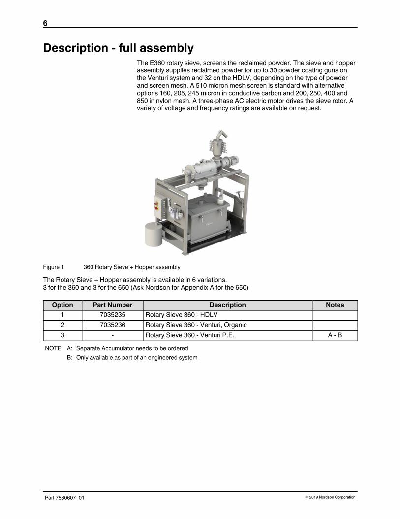
Description - full assemblyThe E360 rotary sieve, screens the reclaimed powder. The sieve and hopperassembly supplies reclaimed powder for up to 30 powder coating guns onthe Venturi system and 32 on the HDLV, depending on the type of powderand screen mesh. A 510 micron mesh screen is standard with alternativeoptions 160, 205, 245 micron in conductive carbon and 200, 250, 400 and850 in nylon mesh. A three-phase AC electric motor drives the sieve rotor. Avariety of voltage and frequency ratings are available on request.
Figure 1 360 Rotary Sieve + Hopper assembly
The Rotary Sieve + Hopper assembly is available in 6 variations. 3 for the 360 and 3 for the 650 (Ask Nordson for Appendix A for the 650)
Option Part Number Description Notes
1 7035235 Rotary Sieve 360 - HDLV
2 7035236 Rotary Sieve 360 - Venturi, Organic
3 - Rotary Sieve 360 - Venturi P.E. A - B
NOTE A: Separate Accumulator needs to be ordered
B: Only available as part of an engineered system

7
Part 7580607_01� 2019 Nordson Corporation
Using the Illustrated Parts List
Numbers in the Item column correspond to numbers that identify parts inillustrations following each parts list. The code NS (not shown) indicates thata listed part is not illustrated. A dash (—) is used when the part numberapplies to all parts in the illustration.
The number in the Part column is the Nordson Corporation part number. Aseries of dashes in this column (------) means the part cannot be orderedseparately.
The Description column gives the part name, as well as its dimensions andother characteristics when appropriate. Indentions show the relationshipsbetween assemblies, subassemblies, and parts.
� If you order the assembly, items 1 and 2 will be included.
� If you order item 1, item 2 will be included.
� If you order item 2, you will receive item 2 only.
The number in the Quantity column is the quantity required per unit,assembly, or subassembly. The code AR (As Required) is used if the partnumber is a bulk item ordered in quantities or if the quantity per assemblydepends on the product version or model.
Letters in the Note column refer to notes at the end of each parts list. Notescontain important information about usage and ordering. Special attentionshould be given to notes.
Item Part Description Quantity Note
— 0000000 Assembly 1
1 000000 � Subassembly 2 A
2 000000 � � Part 1

8
Part 7580607_01 � 2019 Nordson Corporation
Configuration 1 - Rotary Sieve 360 - HDLV
1
2
3
4
5
5
3
4
3
2 6
3
4
3
3
7
8
9
Figure 2 360 Sieve Venting and Parts List - Configuration 1
Item Part Description Quantity Note
- 7035235 ROTARY SIEVE 360 - HDLV - COMPLETE ASSEMBLY - -
- 7035262 � STAND ASSEMBLY, ROTARY SIEVE 360, HDLV - -
- 7035256 � KIT, INSTALLATION, HDLV ROTARY SIEVE - -
1 376999 � � TUBE, RUBBER, 100mm diameter, 2m long 1 A
2 970970 � � CLAMP,HOSE,NO.52 2 A
3 970966 � � CLAMP,HOSE 6 A
4 1008082 � � HOSE,FLEXIBLE,3 METER 1 A - C
5 7033415 � � VENT,45DEG W/BAFFLE 50MM DIA,CYCLONE 2 A
6 243052 � � HOSE,FLEXIBLE,10-FT LENGTH, 3-1/2" DIA 1 A - C
7 144837 � � BUCKET, SCRAP, SIEVE, 5 GAL 1 A
N/S 7033414 � � VENT, 45DEG W/BAFFLE 90MM DIA, HOPPER 1 A - B
8 7033450 � SIEVE, ROTARY, E360B + PNEUMATIC KIT 1 -
9 7035259 � HOPPER, HDLV 1 -
NOTE A: Included in the installation kit 7035256
B: This is to be fixed to the point at which you will connect the purge clean hose, item 6
C: Cut to desired length
AR: As Required
NS: Not Shown
Note: Care must be taken to ensure there is no sag in the venting hoses as this could allow powder tocollect inside and block the venting flow. Pay attention to the location of the vents (8).

9
Part 7580607_01� 2019 Nordson Corporation
Dimensions - Configuration 1
1170
1990
1335800
1581
Figure 3 360 Assembled Dimensions - Configuration 1

10
Part 7580607_01 � 2019 Nordson Corporation
Configuration 2 - Rotary Sieve 360 - Venturi
1
2
34
3
5
5
3
4
3
3
4
3
6
7
8
Figure 4 360 Sieve Venting - Configuration 2
Item Part Description Quantity Note
- 7035236 ROTARY SIEVE 360 - VENTURI, ORGANIC - COMPLETEASSEMBLY
- -
- 7035263 � STAND ASSEMBLY, ROTARY SIEVE 360, VENTURI - -
- 7035257 � KIT, INSTALLATION, VENTURI ROTARY SIEVE - -
1 376999 � � TUBE, RUBBER, 100mm diameter, 2m long 1 A
2 970970 � � CLAMP,HOSE,NO.52 2 A
3 970966 � � CLAMP,HOSE 6 A
4 1008082 � � HOSE,FLEXIBLE,3 METER 1 A - B
5 7033415 � � VENT,45DEG W/BAFFLE 50MM DIA,CYCLONE 2 A
6 144837 � � BUCKET, SCRAP, SIEVE, 5 GAL 1 A
7 7035260 � HOPPER, VENTURI 1 -
8 7033450 � SIEVE, ROTARY, E360B + PNEUMATIC KIT 1 -
NOTE A: Included in the installation kit 7035257
B: Cut to desired length
AR: As Required
NS: Not Shown
Note: Care must be taken to ensure there is no sag in the venting hoses as this could allow powder tocollect inside and block the venting flow. Pay attention to the location of the vents (5).

11
Part 7580607_01� 2019 Nordson Corporation
Dimensions - Configuration 2
1170
1990
800
13351519
Figure 5 360 Assembled Dimensions - Configuration 2

12
Part 7580607_01 � 2019 Nordson Corporation
Configuration 3 - Rotary Sieve 360 - Venturi, PE
2
2
2
4
3
1
7
8
6
3
35
9
10
Figure 6 360 Sieve Venting and Parts List - Configuration 3
Item Part Description Quantity Note
- - ROTARY SIEVE 360 - VENTURI, PE COMPLETE ASSEMBLY - -
- 7035263 � STAND ASSEMBLY, ROTARY SIEVE 360, VENTURI - -
- 7035257 � KIT, INSTALLATION, VENTURI ROTARY SIEVE - -
1 376999 � � TUBE, RUBBER, 100mm diameter, 2m long 1 A - B
2 970970 � � CLAMP,HOSE,NO.52 3 A
3 970966 � � CLAMP,HOSE 4 A
4 1008082 � � HOSE,FLEXIBLE,3 METER 1 A - B
5 7033415 � � VENT,45DEG W/BAFFLE 50MM DIA,CYCLONE 1 A
6 144837 � � BUCKET, SCRAP, SIEVE, 5 GAL 1 A
7 7035260 � HOPPER, VENTURI 1 -
8 7033450 � SIEVE, ROTARY, E360B + PNEUMATIC KIT 1 -
9 7033471 � SEPERATOR,MAGNETIC,SIEVE,E360B 1 C
10 7033470 � ACCUMULATOR,MINI,SIEVE,E360B,W/4 HOSE BR 1 -
NOTE A: Included in the installation kit 7035257
B: Cut to desired length
C: Order magnets separately - see figure 11
AR: As Required
NS: Not Shown
Note: Care must be taken to ensure there is no sag in the venting hoses as this could allow powder tocollect inside and block the venting flow. Pay attention to the location of the vents (2 & 7).

13
Part 7580607_01� 2019 Nordson Corporation
Dimensions - Configuration 3
1170
2673
800
13351519
Figure 7 360 Assembled Dimensions - Configuration 3

14
Part 7580607_01 � 2019 Nordson Corporation
Description and Parts - HDLV - 150L Powder FeedHopper
The HDLV-150L Powder Feed Hopper is used to hold the virgin andreclaimed powder when using Nordson HDLV powder feed pumps. It comesfitted with casters and removable lid for easy operator access. Fitted withlevel sensors, it automatically monitors the powder level and maintains therequired level of powder.
7
Figure 8 HDLV-150L Hopper assembly
Item Part Number Description Notes
- 7035259 Hopper, 150L - HDLV
1 - Vent Hose Adaptor
2 1070199 Inspection Cover
3 - Air supply fitting
4 - HDLV Powder Pick-Up Lance Inlet
5 - Powder Inlet for Sieve Connection
6 7032221 PROBE,LEVEL SENSOR,24VDC ATEX,PNP,90 DEG
7 7033472 FLUID BED,HOPPER,150L
HDLV-150L Hopper assembly Specifications
Powder Capacity 150 litre
HDLV apertures 2 - Pick-Up Lance (32 guns max)
Dimensions in mm (L x D x H) 1025x600x730 (includes castors and latches)
Capacity 70kg
Fluidising Air Pressure 1.0-2.7 bar (15-40 psi)
Fluidising Air Tubing diameter 10 mm (ring main)

15
Part 7580607_01� 2019 Nordson Corporation
Description and Parts - Venturi - 150L Powder FeedHopper
The Venturi - 150L Powder Feed Hopper is used to hold the virgin andreclaimed powder when using Nordson Encore powder feed pumps. Itcomes fitted with casters and removable lid for easy operator access. Fittedwith level sensors, it automatically monitors the powder level and maintainsthe required level of powder.
Powder pumps and pick-up lances must be ordered separately.
7
Figure 9 Venturi - 150L Hopper assembly
Item Part Number Description Notes
- 7035260 Hopper, 150L - Venturi
1 - Vent Hose Adaptor
2 1070199 Inspection Cover
3 7033472 FLUID BED,HOPPER,150L
4 1095922 PUMP ASSY,CORONA,ENCORE GEN II,PKG
5 - Powder Inlet for Sieve Connection
6 7032221 PROBE,LEVEL SENSOR,24VDC ATEX,PNP,90 DEG
7 7033472 FLUID BED,HOPPER,150L
Venturi - 150L Hopper assembly Specifications
Powder Capacity 150 litre
Venturi Pumps Up to 30 pumps
Dimensions in mm (L x D x H) 1025x600x730 (includes castors and latches)
Capacity 70kg
Fluidising Air Pressure 1.0-2.7 bar (15-40 psi)
Fluidising Air Tubing diameter 10 mm (ring main)

16
Part 7580607_01 � 2019 Nordson Corporation
Description - Mini CycloneThe Mini Cyclone is used as an accumulator for virgin and reclaimed powder.Both are fed to the Mini Cyclone in order to mix and blend prior to sieving. Bydefault, it has usable 2 inlets with a possibility to add a further 8 connectionsif required.
1
34
2
6
5
Figure 10 Mini Cyclone assembly
Item Description Notes
1 Mini Cyclone Body
2 Over centre clamp- GH-40323-SS
3 Mini cyclone lid
4 Push in fitting 8 mm
5 Blind Plug 1/2"
6 Hose Tail 1/2" 13mm
Dimensions
Height (including top vent) 532 mm
Length (over inlet tubes) 250 mm
Depth (excluding top vent) 160 mm

17
Part 7580607_01� 2019 Nordson Corporation
Description - Magnetic SeparatorThe Magnetic Separator is used to remove the finest magnetic particles thatcould contaminate powder, particularly with porcelain enamel powders.
WARNING: Magnetic - not to be used by operators fitted with a pacemaker
ÎÎ
ÎÎ
ÎÎ
ÎÎ
ÏÏÏ ÏÏÏÏÏÏÏÏÏÏÏÏÏÏ
ÏÏ
ÏÏÏÏ
ÏÏÏÏÏÏ
ÏÏÏÏÏÏÏÏÏÏÏÏÏÏÏÏÏÏ
ÌÌ
ÑÑÑÑ
2
1
Figure 11 Magnetic Separator assembly
Item Part Number Description Notes
- 7033471 SEPERATOR,MAGNETIC,SIEVE,E360B
1 1018902 GRATE,TRAMP IRON,3 TUBE,8.5 X6 A
2 1018903 GRATE,TRAMP IRON,4 TUBE,8.5 X6 A
NOTE: Magnets are ordered separately. One set of each item, 1 & 2, arerequired for each assembly.
Dimensions
Height 211 mm
Length 225 mm
Depth 174 mm (+ 41 mm for handle)

18
Part 7580607_01 � 2019 Nordson Corporation
Description - AccumulatorThe Accumulator is used to receive and mix both virgin and reclaimedpowder, prior to entering the sieve. By default, it has usable 8 inlets with apossibility to add more if required. The Accumulator is particularly used withPorcelain Enamel powders and is capable of handling higher volumes ofpowder than the Mini Cyclone.
1
2
3
4
5
6
7
Figure 12 Accumulator assembly
Item Part Number Description Notes
- 7033470 ACCUMULATOR,MINI,SIEVE,E360B,W/4 HOSE BR
1 - Body, Accumulator
2 - Cover, Separator, 16 Inlet, St.St.
3 - Fitting, Pneumatic, Elbow - SMC
4 7033473 BRACKET,SUPPORT,TRANSFER HOSE A
5 - Fitting, G1/2 - 13 mm I/D Hose
6 - Vent, Accumulator
7 - Cap, PVC, Inlet
Note: 4 off are supplied with a standard delivery.
19
Part 7580607_01� 2019 Nordson Corporation
Operation
WARNING: Allow only qualified personnel to perform the following tasks.Follow the safety instructions in this document and all other relateddocumentation.
1. Before starting your powder coating system, make sure of the following:
All air tubing, transfer hoses, vent & waste hoses and electrical cables aresecurely connected.
All doors are correctly installed and closed/clamped to the housing.
2. Turn on the system compressed air supply and electrical power.
3. Start the booth exhaust fan. In most systems, this will start the sieve motor.
4. Set the sieve air pressures and flow rates.
Sieve Configurations Fine Pressure Valve Restriction Valve Festo VA ¼” Air in Nl/min
All 360 Assemblies 2 bar 5 (4.75) cycles open 180 - 200
All 650 Assemblies 2 bar 5.25 cycles open 250 - 280
5. Adjust the vent-assist air pressure.
6. Apply the following settings:
Mini Cyclone - 1.5 - 2 bar (application depending)
Hopper fluidisation - 1.5 - 2.5 bar (application depending)
Sieve seals - 2 bar
NOTE: Check the air regulator and restriction valve settings when you startthe system. Check the restriction valve periodically during the day to makesure air is being supplied to the bearings. Check the bearings for powderwhen you are cleaning the sieve. If the lip seals are undamaged, but powderhas contaminated the bearings, increase the purge air pressure.
Air quality must be according to ISO 8573.1 Class 1:4:2
Incoming air pressure must not exceed 7 bar ,maximum.

20
Part 7580607_01 � 2019 Nordson Corporation
Maintenance
WARNING: Allow only qualified personnel to perform the following tasks.Follow the safety instructions in this document and all other relateddocumentation.
NOTE: Maintenance procedures given here are for the general assemblyonly. Refer to your system component manuals for maintenance proceduresfor all other system equipment. For all maintenance requirements of therotary sieve, please refer to the AZO E360B technical manual; this can besupplied by Nordson upon request.
Daily Maintenance Note: You may need to perform these procedures more or less often,depending on your application requirements.
Component Maintenance Procedure
Cables, Tubing, andFeed Hoses
Check all external cables, powder hoses, and air tubing for damage. Repair orreplace as necessary
HDLV Transfer Pumps Purge the pumps. Inspect the pinch valve body for signs of powder leakage. Ifpowder is present in the pinch valve section, replace the pinch valves. Refer tothe Prodigy HDLV High-Capacity pump manual for repair procedures
Powder Supply Check the powder supply level regularly and add powder as necessary
Compressed Air Supply Check the compressed air dryers and filters. Drain filters if needed. Performmaintenance as necessary
Enclosure Clean the interior and exterior of the Rotary Sieve Assembly. Check allequipment ground connections
Venting Check and clean sieve and hopper venting hoses
Hopper Check hopper fluidisation is correct. Gently simmering evenly.

21
Part 7580607_01� 2019 Nordson Corporation
Periodic Maintenance Note: You may need to perform these procedures more or less often,depending on your application requirements.
Component Maintenance Procedure
Compressed Air System Open the drop leg and use a clean, white cloth to check for contaminants.Correct any problems immediately. Drain the air filters and change theelements as necessary.
Electrical System Tighten all electrical connections and inspect tor loose or broken wires. Checkthe electrical system tor electrical safety every 12 months. The system mustcomply with all local, state, and federal codes.
System Grounds Check all equipment grounds. Electrical equipment must be groundedaccording to the relevant code. For maximum transfer efficiency and safety,electrostatic equipment must be grounded to provide a complete circuit fromthe product, through the hangers, conveyors booth and back to the guncontrollers.
Refer to Grounding in the Safety section of this manual and to publicationnumber TCTT-06-3881 on the Nordson emanuals website(http://emanuals.nordson.com/finishing) for more information on powdercoating system grounding.
Air Tubing Pressurise the system and identify if there any air leaks. Replace or repair anydamaged fittings or tubing.
Sieve Maintenance Refer to the AZO Rotary Sieve manual for more information on sievemaintenance. Available upon request from Nordson.
Festo Valve Island Maintenance Manual: Valve terminals MPA-S (Typ32)
https://www.festo.com/cat/de_de/data/doc_engb/PDF/EN/TYP32_EN.PDF

22
Part 7580607_01 � 2019 Nordson Corporation
Troubleshooting
WARNING: Allow only qualified personnel to perform the following tasks.Follow the safety instructions in this document and all other relateddocumentation.
These troubleshooting procedures cover only the most common problems. Ifyou cannot solve a problem with the information given here, contact yourlocal Nordson representative for help.
Problem Possible Cause Corrective Action
1. Good powder in thewaste container
Powder feed rate exceeds sievecapacity
Reduce the venturi transfer-pump airpressure. If a HDLV system, contactyour Nordson representative.
Erratic or pulsating feed rate.Heavy surges may exceed sievecapacity
Check the transfer-pump air supplyand pressure. Check the transferpumps, pickup tubes, and hoses forblockages. Check the fluidising platesand the powder in the colour modulehoppers for contamination.
Too many oversized particles inreclaimed powder
Check the powder in the colourmodule for contamination
Screen mesh is too fine Change to a more coarse screenmesh. Refer to AZO E360B technicalmanual for procedure.
Loose screens Remove the screen frame from thesieve. Adjust the screen tensionaccording to the AZO E360Btechnical manual.
Clogged screens Clean or replace the screen. Checkthe powder for contamination. Addnew powder to the hopper. Too largea ratio of reclaimed-to-new powdercan cause clogging.
Vent-assist air pressure too low, orhose to scrap container and/orcontainer not air tight
Adjust the vent-assist air pressure.Check the hose and scrap containerconnections and seals.
Sieve not level, discharge endpitched down
Level the sieve and/or the feedhopper.
2. Powder backing up inthe accumulator
Restriction in sieve and/or powderpath causing blockage
Clean the powder path
Vent-assist air pressure too high Adjust the vent-assist air pressure
Repair Contact your Nordson representative for repair information.

23
Part 7580607_01� 2019 Nordson Corporation
Parts To order parts, call the Nordson Industrial Coating Systems CustomerSupport Center at (800) 433‐9319 or contact your local Nordsonrepresentative.
Part Description Note
7033452 SCREEN 0,850MM,NYLON,ROTARY SIEVE E360B A
7033453 SCREEN 0,400MM,NYLON,ROTARY SIEVE E360B A
7033454 SCREEN 0,250MM,NYLON,ROTARY SIEVE E360B A
7033455 SCREEN 0,200MM,NYLON,ROTARY SIEVE E360B A
7033456 SCREEN 0,510MM,CARBON,ROTARY SIEVE E360B A
7033457 SCREEN 0,245MM,CARBON,ROTARY SIEVE E360B A
7033458 SCREEN 0,205MM,CARBON,ROTARY SIEVE E360B A
7033459 SCREEN 0,160MM,CARBON,ROTARY SIEVE E360B A
NOTE A: 2 required per machine

24
Part 7580607_01 � 2019 Nordson Corporation
Specifications - Rotary Sieve 360 Assembly
ElectricalUnit Value
Voltage (V) 400
Power (kW) 0.75
Frequency (Hz) 50
Protection IP54
Noise
Less than 80dB (A) measured at a distance of 1 m from the surface of theunit and at a height of 1.6 m.

25
Part 7580607_01� 2019 Nordson Corporation
DiagramsDescription Part Number
Control Box - Sieve E360 & E650 47.20-00.00 A
Pneumatic - Sieve E360 & E650 47.20-00.00 B

26
Part 7580607_01 � 2019 Nordson Corporation
X

27
Part 7580607_01� 2019 Nordson Corporation
X

28
Part 7580607_01 � 2019 Nordson Corporation