rotary actuators applicable auto switch variations
TRANSCRIPT

4PneumaticsBest
Rotary Actuators, Air Grippers
Rotary Actuators Applicable Auto Switch Variations
Size
Applicableseries
Pag
e
Ree
d A
uto
Sw
itch
2-colorindication
Rail
Grommet
Grommet
Grommet
Grommet
Grommet
Connector
Connector
Tie-rod
Direct
Rail
799
800
801
802
803
804
805
806
806
807
807
808
809
CD
RA
1
CD
RB
CD
RQ
2
CR
J
MR
Q
MD
SU
MS
Q
MS
Z
CD
RQ
2X
MS
QX
30 50 to
100
10, 1
5
20 to
100
10 t
o 4
0
05, 1
32, 4
0
1, 3
7, 2
0
1, 7
10 to
200
10 t
o 5
0
10 t
o 4
0
10 t
o 5
0Auto switch modelType
Autoswitch
mountingstyle
Electricalentry
So
lid S
tate
Au
to S
wit
ch
2-color indicationwith diagnostic
output
2-colorindication
Waterresistant2-color
indication
With timer
Rail
Rail
Rail
Rail
Rail
Grommet
Grommet
Grommet
Grommet
Grommet
Grommet
Grommet
Grommet
Grommet
Connector
Connector
Tie-rod
Tie-rod
Tie-rod
Direct
Direct
Trimmer
767
768
769
770
771
771
771
772
772
772
772
773
774
775
776
777
778
779
780
781
782
783
784
785
786
787
788
789
Grommet
Direct Grommet
Direct
D-A72/A73/A80
D-A73C/A80C
D-90/97
D-90A/93A
D-R731/R732
D-R801/R802
D-R731C/R732C
D-R801C/R802C
D-A79W
D-A59W
D-A72H/A73HD-A76H/A80H
D-A53/A54/A56D-A64/A67
D-A90/A93/A96D-A90V/A93V/A96V
D-J79C
D-F79/F7P/J79
D-F7NV/F7PV/F7BV
D-F59/F5P/J59/J51
D-S991/S992/D-S99V1/S99V2
D-T991/T992/D-T99V1/T99V2
D-S9P1/S9P2/D-S9PV1/S9PV2
D-S791/S792
D-T791/T792
D-S7P1/S7P2
D-T791C/T792C
D-F79W/F7PW/J79W
D-F7NWV/F7BWV
D-F59W/F5PW/J59W
D-F79F
D-F59F
D-F7BAL/F7BAVL
D-F5BAL
D-Y7BAL
D-M9NAL/M9PAL/M9BALD-M9NAVL/M9PAVL/M9BAVL
D-F7NTL
D-F5NTL
D-M9N/M9P/M9BD-M9NV/M9PV/M9BV
D-Y59A/Y7P/Y59BD-Y69A/Y7PV/Y69B
D-Y7NW/Y7PW/Y7BWD-Y7NWV/Y7PWV/Y7BWV
D-M9NW/M9PW/M9BWD-M9NWV/M9PWV/M9BWV
D-Y7K
D-F8N/F8P/F8B
762
P0761-P0763-E.qxd 08.9.29 4:01 PM Page 762
Courtesy of Steven Engineering, Inc.-230 Ryan Way, South San Francisco, CA 94080-6370-Main Office: (650) 588-9200-Outside Local Area: (800) 258-9200-www.stevenengineering.com
Applicable Auto Switch Variations
Size
Applicableseries
Pag
e
2-colorindication
Rail
Grommet
Grommet
Grommet
Grommet
Grommet
Connector
Connector
Tie-rod
Direct
Rail
799
800
801
802
803
804
805
806
806
807
807
808
809
MH
Z(L
)2
MH
ZJ2
MH
F2
MH
L2
MD
HR
MH
K(L
)2
MH
SM
HS
L
MH
SH
MH
SJ
MH
C2
MH
T2
MH
W2
MH
Y2
MR
HQ
6 10 16 20 to
40
10 16 20, 2
5
8 to
20
10 to
40
10 to
30
12 to
25
16 to
25
32 to
63
80 to
125
16 20 to
80
6 10 to
25
32 to
63
20 to
50
10 to
25
10 to
25
Air Grippers Applicable Auto Switch Variations
2-color indicationwith diagnostic
output
2-colorindication
Waterresistant2-color
indication
With timer
Rail
Rail
Rail
Rail
Grommet
Grommet
Grommet
Grommet
Grommet
Grommet
Grommet
Grommet
Connector
Connector
Tie-rod
Tie-rod
Tie-rod
Direct
Direct
Trimmer
767
768
769
770
771
771
771
772
772
772
772
773
774
731
775
776
777
778
779
780
781
782
783
784
785
786
787
788
789
Grommet
Direct Grommet
Direct
Rail Grommet
D-
Ro
tary
Act
uat
ors
, Air
Gri
pp
ers
Auto switch modelType
Autoswitch
mountingstyle
Electricalentry
D-A72/A73/A80
D-A73C/A80C
D-90/97
D-90A/93A
D-R731/R732
D-R801/R802
D-R731C/R732C
D-R801C/R802C
D-A79W
D-A59W
D-A72H/A73HD-A76H/A80H
D-A53/A54/A56D-A64/A67
D-A90/A93/A96D-A90V/A93V/A96V
D-J79C
D-F79/F7P/J79
D-F7NV/F7PV/F7BV
D-F59/F5P/J59/J51
D-S991/S992/D-S99V1/S99V2
D-T991/T992/D-T99V1/T99V2
D-S9P1/S9P2/D-S9PV1/S9PV2
D-S791/S792
D-T791/T792
D-S7P1/S7P2
D-T791C/T792C
D-F79W/F7PW/J79W
D-F7NWV/7BWV
D-F59W/F5PW/J59W
D-F79F
D-F59F
D-F7BAL/F7BAVL
D-F5BAL
D-Y7BAL
D-M9NAL/M9PAL/M9BALD-M9NAVL/M9PAVL/M9BAVL
D-F7NTL
D-F5NTL
D-M9N/M9P/M9BD-M9NV/M9PV/M9BV
D-Y59A/Y7P/Y59BD-Y69A/Y7PV/Y69B
D-Y7NW/7PW/7BWD-Y7NWV/7PWV/7BWVD-M9NW/M9PW/M9BW
D-M9NWV/M9PWV/M9BWV
D-Y7K
D-F8N/F8P/F8B
D-M9N/M9P/M9B-746
Ree
d A
uto
Sw
itch
So
lid S
tate
Au
to S
wit
ch
763
P0761-P0763-E.qxd 08.9.29 4:01 PM Page 763
Courtesy of Steven Engineering, Inc.-230 Ryan Way, South San Francisco, CA 94080-6370-Main Office: (650) 588-9200-Outside Local Area: (800) 258-9200-www.stevenengineering.com

Prior to UseAuto Switches Common Specifications 1
Auto Switches Common Specifications
Leakage current
Operating time
Impact resistance
Insulation resistance
Withstand voltage
Ambient temperature
Enclosure
Type Reed auto switch
None
1.2 ms
300 m/s2
1500 VAC for 1 minute (1)
(Between lead wire and case)
Solid state auto switch
3-wire: 100 μA or less, 2-wire: 0.8 mA or less
1 ms or less (3)
1000 m/s2 (4)
1000 VAC for 1 minute(Between lead wire and case)
50 MΩ or more at 500 M VDC (Between lead wire and case)
–10 to 60°C
IEC60529 Standard IP67 (2)
Specific Product PrecautionsRefer to the Auto Switch Precautions on pages 362 to 365 before using auto switches.
∗ 1) Electrical entry: Connector type (A73C/A80C/R73C/R80C) and D-9/9A type: 1000 VAC/min. (Between lead wire and the case)
∗ 2) The trimmer type amplifier section (D-RK) conforms to IP40.∗ 3) Excluding the solid state auto switches with a timer (F7NTL/F5NTL types). The operating time for
D-J51 is 2 ms or less.∗ 4) 980 m/s2 for the trimmer type sensor section, 98 m/s2 for the amplifier section.
Lead WireLead wire length indication Solid state auto switch oil resistant flexible cabtire cord indication
Lead wires with a connector indication∗ Applicable for the connector type (D-C) only.
Note 1) Lead wire length Z: 5 mApplicable auto switchesReed auto switch: D-A73(C) (H)/A80C, R73(C), R80(C)
D-A53/A54, D-90A/93A Solid state auto switch: Manufactured upon receipt of order as standard.
Note 2) The standard lead wire length for solid state auto switches with a timer, water resistant 2-color indication solid state auto switches and trimmer auto switches is 3 m. (0.5 m is not available.)
Note 3) 1 m (M): D-M9(W)(V) onlyNote 4) Lead wire length tolerance
Add a -61 at the end of the part number for the solid state auto switch flexible cord except D-Y59, D-Y69, D-Y7, D-M9/M9V, D-M9W/M9WV, and D-M9AL/M9AVL.
Lead wire lengthNilMLZ
N∗
0.5 m1 m3 m5 m
None
(Example)
Lead wire length
0.5 m
1 m
3 m
5 m
Tolerance
±15 mm
±30 mm
±90 mm
±150 mm
(D-Y59, D-Y69 and D-Y7 series use flexible lead wire as standard. )
(Example)
D-F7PL-Flexible specification
61
Model
D-LC05
D-LC30
D-LC50
Lead wire length
0.5 m
3 m
5 m
Part No. of Lead Wires with Connectors(Applicable only for connector type)
LD-M9BW
764
P0764-P0810-E.qxd 08.9.29 4:03 PM Page 764
Courtesy of Steven Engineering, Inc.-230 Ryan Way, South San Francisco, CA 94080-6370-Main Office: (650) 588-9200-Outside Local Area: (800) 258-9200-www.stevenengineering.com

Prior to UseAuto Switches Common Specifications 2
Refer to the Auto Switch Precautions on pages 362 to 365 before using auto switches.
Contact Protection Box: CD-P11, CD-P12
Contact Protection Box Specifications
Load voltage
Max. load current
Part no. CD-P11 CD-P12
∗ Lead wire length — Auto switch connection side 0.5 mLoad connection side 0.5 m
100 VAC or less
25 mA
200 VAC
12.5 mA
24 VDC
50 mA
To connect a switch unit to a contact protection box, connect the lead wire from the side of the contact protection box marked SWITCH to the lead wire coming out of the switch unit. Keep the switch as close as possible to the contact protection box, with a lead wire length of no more than 1 meter.
Contact Protection Box Connection
Hysteresis is the distance between the position at which piston movement operates an auto switch to the position at which reverse movement turns the switch off. This hysteresis is included in part of the operating range (one side).
Auto Switch Hysteresis
Contact Protection Box/Dimensions
Contact Protection Box Internal CircuitCD-P11
CD-P12
<Applicable switch models>D-A7/A8, D-A7H/A80H, D-A73C/A80C, R73/R80, R73C/R80C, D-9/9A, D-A9/A9V, and D-A79W typeThe auto switches above do not have a built-in contact protection circuit. A contact protection box is not required for solid state auto switches due to their construction.q Where the operation load is an inductive load.w Where the wiring length to load is greater than 5 m.e Where the load voltage is 100/200 VAC.
Therefore, use a contact protection box with the switch for any of the above cases:The contact life may be shortened (due to permanent energizing conditions.)D-A72(H) must be used with the contact protection box regardless of load types and lead wire length since it is greatly affected by loads.(Where the load voltage is 110 VAC)When the load voltage is increased by more than 10% to the rating of applicable auto switches (except D-A73C/A80C/R73C/R80C/90/97/A79W) above, use a contact protection box (CD-P11) to reduce the upper limit of the load current by 10% so that it can be set within the range of the load current range, 110 VAC.
Even for the built-in contact protection circuit type (D-A54/A64, D-A59W), use the contact protection box when the wiring length to load is very long (over 30 m) and PLC (Programmable Logic Controller) with a large inrush current is used.
Specific Product Precautions
Note) Hysteresis may fluctuate due to the operating environment.Please contact SMC if hysteresis causes an operational problem.
Auto switch
Switch operating position(ON) Hysteresis Reed auto switch: 2 mm or less
Solid state auto switch: 1 mm or less
Switch operating position(OFF)
Note)
Surge absorber
Zener diode
Chokecoil
OUT Brown
OUT Blue
OUT (+) Brown
OUT (–) Blue
~
Chokecoil
765
D-
P0764-P0810-E.qxd 08.9.29 4:03 PM Page 765
Courtesy of Steven Engineering, Inc.-230 Ryan Way, South San Francisco, CA 94080-6370-Main Office: (650) 588-9200-Outside Local Area: (800) 258-9200-www.stevenengineering.com

Basic Wiring
Solid state 3-wire, NPN
• Sink input specifications 3-wire, NPN
• 3-wire
• 2-wire
2-wire (Solid state)
• Source input specifications 3-wire, PNP
OR connection for NPN output
2-wire with 2-switch AND connection 2-wire with 2-switch OR connection
2-wire 2-wire
Solid state 3-wire, PNP
Load voltage at ON = Power supply voltage – Residual voltage x 2 pcs.= 24 V – 4 V x 2 pcs.= 16 V
Example: Power supply is 24 VDCInternal voltage drop in auto switch is 4 V.
Load voltage at OFF = Leakage current x 2 pcs. x Load impedance= 1 mA x 2 pcs. x 3 kΩ= 6 V
Example: Load impedance is 3 kΩ.Leakage current from auto switch is 1 mA.
Auto switch 1
Auto switch 2
Load
BrownBlackBlue
BrownBlackBlue
Auto switch 1
Auto switch 2
Brown
Blue
Brown
Blue
LoadAuto switch 1
Auto switch 2
Brown
Blue
Brown
Blue
Load
Auto switch
Auto switch
Auto switch
Example of AND (Series) and OR (Parallel) Connection
Example of Connection with PLC (Programmable Logic Controller)
2-wire (Reed)
AND connection for NPN output(Using relays)
Auto switch 1
Brown
Auto switch 2
BlackBlue
Load
BrownBlackBlue
AND connection for NPN output(Performed with auto switches only)
The indicator lights will light up whenboth auto switches are turned ON.
When two auto switches are connected in series, a load may malfunction because the load voltage will decline when in the ON state.The indicator lights will light up when both of the auto switches are in the ON state.
Prior to UseAuto Switches Connection and Example
Main curcuitof switch
Brown
Black
Blue
Load
Brown
Black
Blue
Main curcuitof switch
Load
Brown
Black
Blue
Main curcuitof switch
(Power supply for switch and load are separate)
Load
Brown
Blue
Brown
Blue
Main curcuitof switch
Main curcuitof switch
Load
Load
Indicatorlight,protectioncircuit,etc.
Brown
Blue
~
~
Brown
Blue
Indicatorlight,protectioncircuit,etc. Load
Load
Auto switch
InputBlack
COM
Brown
Blue
PLC internal circuit
InputBlack
COM
Brown
Blue
PLC internal circuit
Input
Blue COM
Brown
PLC internal circuit PLC internal circuit
InputBlue
COMBrown
Connect according to the applicable PLC input specifications, as the connection method will vary depending on the PLC input specifications.
Auto switch 1
Brown
Auto switch 2
BlackBlue
Relay
Relay
BrownBlackBlue
Load
Relay contact
(Solid state auto switch)When two auto switches are connected in parallel, malfunction may occur because the load voltage will increase when in the OFF state.
(Reed auto switch)Because there is no current leakage, the load voltage will not increase when turned OFF. However, depending on the number of auto switches in the ON state, the indicator lights may sometimes grow dim or not light up, due to the dispersion and reduction of the current flowing to the auto switches.
766
P0764-P0810-E.qxd 08.9.29 4:03 PM Page 766
Courtesy of Steven Engineering, Inc.-230 Ryan Way, South San Francisco, CA 94080-6370-Main Office: (650) 588-9200-Outside Local Area: (800) 258-9200-www.stevenengineering.com
Auto Switch Internal Circuit
D-F79
D-J79
D-F7P
Auto Switch Specifications
Mass
Dimensions
Auto switch model
0.5
3
5
D-F79 D-F7P D-J79
(g)
(mm)
Solid State Auto SwitchRail Mounting StyleD-F79/D-F7P/D-J79
Grommet
Lead wire length(m)
D-F7, D-J79 (With indicator light)PLC: Programmable Logic Controller
Auto switch model
Wiring type
Output type
Applicable load
Power supply voltage
Current consumption
Load voltage
Load current
Internal voltage drop
Leakage current
Indicator light
Standard
D-F79
NPN
28 VDC or less
40 mA or less
1.5 V or less(0.8 V or less
at 10 mA load current)
D-F7P
PNP
—
80 mA or less
0.8 V or less
Red LED illuminates when turned ON.
CE marking
3-wire
IC circuit, Relay, PLC
5, 12, 24 VDC (4.5 to 28 VDC)
10 mA or less
100 μA or less at 24 VDC
D-J79
2-wire
—
24 VDC Relay, PLC
—
—
24 VDC (10 to 28 VDC)
5 to 40 mA
4 V or less
0.8 mA or less at 24 VDC
13
57
92
11
50
81
13
57
92
Refer to SMC website for the details of the products conforming to the international standards.
• Lead wires — Oilproof heavy-duty vinyl cord, ø3.4, 0.2 mm2, 3 cores (Brown, Black, Blue),2 cores (Brown, Blue), 0.5 m
Note 1) Refer to page 764 for solid state auto switch common specifications.Note 2) Refer to page 764 for lead wire lengths.
Indicator light
Most sensitive position
ø3.2 mounting hole
Mai
n ci
rcui
t of
sw
itch
Mai
n ci
rcui
t of
sw
itch
Mai
n ci
rcui
t of
sw
itch
OUTBlack
DC (+)Brown
DC (–)Blue
OUTBlack
DC (+)Brown
DC (–)Blue
OUT (+)Brown
OUT (–)Blue
767
D-
P0764-P0810-E.qxd 08.9.29 4:03 PM Page 767
Courtesy of Steven Engineering, Inc.-230 Ryan Way, South San Francisco, CA 94080-6370-Main Office: (650) 588-9200-Outside Local Area: (800) 258-9200-www.stevenengineering.com
Auto Switch Internal Circuit
D-F7NV
D-F7BV
D-F7PV
Mass
Dimensions
Auto switch model
0.5
3
5
13
57
92
13
57
92
11
50
81
D-F7NV D-F7PV D-F7BV
(g)
(mm)
GrommetElectrical entry: Perpendicular
Lead wire length(m)
D-F7V (With indicator light)Auto switch model
Wiring type
Output type
Applicable load
Power supply voltage
Current consumption
Load voltage
Load current
Internal voltage drop
Leakage current
Indicator light
Standard
D-F7NV
NPN
28 VDC or less
40 mA or less
1.5 V or less(0.8 V or less
at 10 mA load current)
D-F7PV
PNP
—
80 mA or less
0.8 V or less
Red LED illuminates when turned ON.
CE marking
D-F7BV
2-wire
—
24 VDC Relay, PLC
—
—
24 VDC (10 to 28 VDC)
5 to 40 mA
4 V or less
0.8 mA or less at 24 VDC
3-wire
IC circuit, Relay, PLC
5, 12, 24 VDC (4.5 to 28 VDC)
10 mA or less
100 μA or less at 24 VDC
Refer to SMC website for the details of the products conforming to the international standards.Auto Switch Specifications
PLC: Programmable Logic Controller
• Lead wires — Oilproof heavy-duty vinyl cord, ø3.4, 0.2 mm2, 3 cores (Brown, Black, Blue),2 cores (Brown, Blue), 0.5 m
Note 1) Refer to page 764 for solid state auto switch common specifications.Note 2) Refer to page 764 for lead wire lengths.
Mai
n ci
rcui
tof
sw
itch
Mai
n ci
rcui
t of
sw
itch
Mai
n ci
rcui
t of
sw
itch
OUTBlack
DC (+)Brown
DC (–)Blue
OUTBlack
DC (+)Brown
DC (–)Blue
OUT (+)Brown
OUT (–)Blue
Indicator light
Most sensitive position
ø3.2 mounting hole
Solid State Auto SwitchRail Mounting StyleD-F7NV/D-F7PV/D-F7BV
768
P0764-P0810-E.qxd 08.9.29 4:03 PM Page 768
Courtesy of Steven Engineering, Inc.-230 Ryan Way, South San Francisco, CA 94080-6370-Main Office: (650) 588-9200-Outside Local Area: (800) 258-9200-www.stevenengineering.com

Auto Switch Internal Circuit
D-J79C
Mass
Dimensions
Auto switch model
0.5
3
5
13
52
83
D-J79C
(g)
(mm)
Solid State Auto SwitchRail Mounting StyleD-J79C
Connector
Lead wire length(m)
D-J79C (With indicator light)Auto switch model
Wiring type
Output type
Applicable load
Power supply voltage
Current consumption
Load voltage
Load current
Internal voltage drop
Leakage current
Indicator light
Standard
D-J79C
2-wire
—
24 VDC Relay, PLC
—
—
24 VDC (10 to 28 VDC)
5 to 40 mA
4 V or less
0.8 mA or less at 24 VDC
Red LED illuminates when turned ON.
CE marking
1. Confirm that the connector is appropriately tightened. If tightened insufficiently, the waterproof performance will deteriorate.
2. Refer to Best Pneumatics No. 2 for the details.
PrecautionsCaution
Refer to SMC website for the details of the products conforming to the international standards.Auto Switch Specifications
PLC: Programmable Logic Controller
• Lead wires — Oilproof heavy-duty vinyl cord, ø3.4, 0.2 mm2, 2 cores (Brown, Blue), 0.5 mNote 1) Refer to page 764 for solid state auto switch common specifications.Note 2) Refer to page 764 for lead wire lengths.Note 3) Lead wires with a connector may be shipped with auto switches.
Mai
n ci
rcui
t of
sw
itch
OUT (+)Brown
OUT (–)Blue
ø3.2 mounting hole
Indicator light
Most sensitive position
769
D-
P0764-P0810-E.qxd 08.9.29 4:03 PM Page 769
Courtesy of Steven Engineering, Inc.-230 Ryan Way, South San Francisco, CA 94080-6370-Main Office: (650) 588-9200-Outside Local Area: (800) 258-9200-www.stevenengineering.com

Auto Switch Internal Circuit
D-F59
D-F5P
D-J59
D-J51
Mass
Dimensions
Auto switch model
0.5
3
5
D-F59 D-F5P D-J59 D-J5123
81
127
23
81
127
21
71
111
21
71
111
(g)
(mm)
Solid State Auto SwitchTie-rod Mounting StyleD-F59/D-F5P/D-J59/D-J51
Lead wire length(m)
Grommet D-F5, D-J5 (With indicator light)Auto switch model
Wiring type
Output type
Applicable load
Power supply voltage
Current consumption
Load voltage
Load current
Internal voltage drop
Leakage current
Indicator light
Standard
D-F59
NPN
28 VDC or less
40 mA or less
1.5 V or less(0.8 V or less at
10 mA load current)
D-F5P
PNP
—
80 mA or less
0.8 V or less
D-J59
—
24 VDC Relay, PLC
—
—
24 VDC (10 to 28 VDC)
5 to 40 mA
4 V or less
0.8 mA or less
at 24 VDC
D-J51
—
AC Relay, PLC
—
—
80 to 260 VAC
5 to 80 mA
14 V or less
1 mA or less at 100 VAC
1.5 mA or less at 200 VAC
—
3-wire
IC circuit, Relay, PLC
5, 12, 24 VDC (4.5 to 28 VDC)
10 mA or less
100 μA or less at 24 VDC
Red LED illuminates when turned ON.
CE marking
2-wire
D-F59/D-F5P/D-J59
D-J51
11
ø7
1.4
16
10
D-J51
Most sensitive position
33
ø4
4.5
12
1466
22
125
7Indicator light
Refer to SMC website for the details of the products conforming to the international standards.(Except D-J51)Auto Switch Specifications
PLC: Programmable Logic Controller
• Lead wires — Oilproof heavy-duty vinyl cord, ø4, 0.3 mm2, 3 cores (Brown, Black, Blue), 2 cores (Brown, Blue), 0.5 m
Note 1) Refer to page 764 for solid state auto switch common specifications.Note 2) Refer to page 764 for lead wire lengths.
Mounting hole
Indicator light
Most sensitive position
Mai
n ci
rcui
t of
sw
itch
Mai
n ci
rcui
t of
sw
itch
OUTBlack
DC (+)Brown
DC (–)Blue
OUTBlack
DC (+)Brown
DC (–)Blue
OUT (~)BrownOUT (~)Blue
Mai
n ci
rcui
t of
sw
itch
Mai
n ci
rcui
t of
sw
itch
OUT (+)Brown
OUT (–)Blue
770
P0764-P0810-E.qxd 08.9.29 4:03 PM Page 770
Courtesy of Steven Engineering, Inc.-230 Ryan Way, South San Francisco, CA 94080-6370-Main Office: (650) 588-9200-Outside Local Area: (800) 258-9200-www.stevenengineering.com

ø3.4Mounting hole
ø3.4Mounting hole
ø3.4Mounting hole
ø3.
4
ø3.4Mounting hole
ø3.
4
Auto Switch Specifications
Dimensions
D-S99(V)1, S99(V)2
D-S9P(V)1, S9P(V)2
Auto Switch Internal CircuitD-S991: Right-hand mountingD-S9P1:D-T991:
D-S992: Left-hand mountingD-S9P2:D-T992:
D-S99V1: Right-hand mountingD-S9PV1:D-T99V1:
D-S99V2: Left-hand mountingD-S9PV2:D-T99V2:
D-T99(V)1, T99(V)2
D-1 D-2
D-V1 D-V2
Grommet
D-S991D-S992
D-S99V1D-S99V2
D-S9P1D-S9P2
D-S9PV1D-S9PV2
D-T991D-T992
D-T99V1D-T99V2
In-line PerpendicularIn-line PerpendicularIn-line Perpendicular
24 VDC relay, PLC
Electrical entry directionWiring typeOutput typeApplicable loadPower supply voltageCurrent consumptionLoad voltageLoad current
Internal voltage drop
Leakage currentIndicator lightStandard
3-wire 2-wireNPN PNP
IC circuit, Relay, PLC5, 12, 24 VDC (4.5 to 28 VDC)
10 mA or less28 VDC or less 24 VDC (10 to 28 VDC)40 mA or less 80 mA or less
0.8 V or less
5 to 40 mA1.5 V or less
(0.8 V or less at load current 10 mA) 4 V or less
100 μA or less at 24 VDC 0.8 mA or less at 24 VDCRed LED illuminates when turned ON.
CE marking
D-S99(V)/D-S9P(V)/D-T99(V) (With indicator light)
Auto switch model
Mass (g)
Solid State Auto SwitchDirect Mounting StyleD-S99(V)/D-S9P(V)/D-T99(V)
D-S990.53 5
124979
D-S99V124679
D-S9P124679
D-S9PV124679
D-T99124679
D-T99V124679
Lead wire length(m)
Auto switch model
(mm)
Refer to SMC website for the details of the products conforming to the international standards.
PLC: Programmable Logic Controller
• Lead wires — Oilproof heavy-duty vinyl cord, ø3.4, 0.2 mm2, 3-wire (Brown, Black, Blue), 2-wire (Brown, Blue), 0.5 m
Note 1) Refer to page 764 for solid state auto switch common specifications.Note 2) Refer to page 764 for lead wire lengths.
Right-hand mounting Left-hand mounting
Right-hand mounting Left-hand mounting
OUTBlack
DC (+)Brown
DC (–)Blue
DC (+)Brown
DC (–)Blue
OUTBlack
OUT (+)Brown
OUT (–)Blue
Mai
n ci
rcui
tof
sw
itch
Mai
n ci
rcui
tof
sw
itch
Mai
n ci
rcui
tof
sw
itch
771
D-
P0764-P0810-E.qxd 08.9.29 4:03 PM Page 771
Courtesy of Steven Engineering, Inc.-230 Ryan Way, South San Francisco, CA 94080-6370-Main Office: (650) 588-9200-Outside Local Area: (800) 258-9200-www.stevenengineering.com

Auto Switch Specifications
Dimensions
Grommet, ConnectorElectrical Entry: In-line
D-2 D-1
D-S791, S792
D-S7P1, S7P2
Auto Switch Internal Circuit
D-T791(C), T792(C)
D-S791: Right-hand mountingD-S7P1:D-T791:
D-S792: Left-hand mountingD-S7P2:D-T792:
D-T792C: Left-hand mountingD-T791C: Right-hand mounting
Auto switch model
Wiring type
Output type
Applicable load
Power supply voltage
Current consumption
Load voltage
Load current
Internal voltage drop
Leakage current
Indicator light
Standard
3-wire 2-wire
IC circuit, Relay, PLC
5, 12, 24 VDC (4.5 to 28 VDC)
D-S7P1, D-S7P2
PNP
80 mA or less
D-S791, D-S792
NPN
10 mA or less
28 VDC or less
40 mA or less
0.8 V or less1.5 V or less
(0.8 V or less at 10 mA)
D-T791, D-T792, D-T791C, D-T792C
24 VDC relay, PLC
24 VDC (10 to 28 VDC)
100 μA or less at 24 VDC 0.8 mA or less at 24 VDC
5 to 40 mA
4 V or less
D-S79/D-T79 (With indicator light)
Red LED illuminates when turned ON.
CE marking
Mass
D-T79C0.5
3
5
14
51
81
Lead wire length(m)
Auto switch model D-T7913
50
80
D-S7P13
50
80
D-S7913
50
80
Solid State Auto SwitchDirect Mounting StyleD-S79/D-S7P/D-T79(C)
(g)
(mm)
Refer to SMC website for the details of the products conforming to the international standards.
PLC: Programmable Logic Controller
Left-hand mounting Right-hand mounting
• Lead wires — Oilproof heavy-duty vinyl cord, ø3.4, 0.2 mm2, 3-wire (Brown, Black, Blue), 2-wire (Brown, Blue), 0.5 m
Note 1) Refer to page 764 for solid state auto switch common specifications.Note 2) Refer to page 764 for lead wire lengths.
Most sensitive position
Most sensitive position
Most sensitive position
Most sensitive position
OUTBlack
DC (+)Brown
DC (–)Blue
DC (+)Brown
DC (–)Blue
OUTBlack
OUT (+)Brown
OUT (–)Blue
Mai
n ci
rcui
tof
sw
itch
Mai
n ci
rcui
tof
sw
itch
Mai
n ci
rcui
tof
sw
itch
772
P0764-P0810-E.qxd 08.9.29 4:03 PM Page 772
Courtesy of Steven Engineering, Inc.-230 Ryan Way, South San Francisco, CA 94080-6370-Main Office: (650) 588-9200-Outside Local Area: (800) 258-9200-www.stevenengineering.com

D-F8 (With indicator light)Grommet
D-F8N
D-F8B
D-F8P
Auto Switch Specifications
Dimensions
Auto switch model
Electrical entry direction
Wiring type
Output type
Applicable load
Power supply voltage
Current consumption
Load voltage
Load current
Internal voltage drop
Leakage current
Indicator light
Standard
D-F8N
Perpendicular
NPN
28 VDC or less
40 mA or less
D-F8B
Perpendicular
2-wire
—
24 VDC relay, PLC
—
—
24 VDC (10 to 28 VDC)
2.5 to 40 mA
4 V or less
0.8 mA or less at 24 VDC
D-F8P
Perpendicular
PNP
—
80 mA or less
0.8 V or less
D-F8N/D-F8P/D-F8B
1.5 V or less(0.8 V or less
at 10 mA load current)
Red LED illuminates when turned ON.
CE marking
100 µA or less at 24 VDC
3-wire
IC circuit, 24 VDC Relay, PLC
5, 12, 24 VDC (4.5 to 28 VDC)
10 mA or less
M2.5 x 4l
Slotted set screw
Indicator light
Most sensitive position
10
4.62.
8
2
4.3
ø2.7
4
3.1
10.9
3
8
Auto Switch Internal CircuitMass
Auto switch model
0.5
3
5
D-F8N7
32
52
D-F8P7
32
52
D-F8B7
32
52
PrecautionsCaution
(g)
(mm)
Lead wire length(m)
Fix the auto switch with the existing screw installed on the auto switch body. The auto switch may be damaged if a screw other than the one supplied is used.
Refer to SMC website for the details of the products conforming to the international standards.
PLC: Programmable Logic Controller
Solid State Auto SwitchDirect Mounting StyleD-F8N/D-F8P/D-F8B
• Lead wires — Oilproof heavy-duty vinyl cord, ø2.7 D-F8N, D-F8P 0.15 mm2 x 3 cores (Brown, Black, Blue)D-F8B 0.18 mm2 x 2 cores (Brown, Blue)
Note 1) Refer to page 764 for solid state auto switch common specifications.Note 2) Refer to page 764 for lead wire lengths.
Mai
n ci
rcui
t of
sw
itch
Mai
n ci
rcui
t of
sw
itch
Mai
n ci
rcui
t of
sw
itch
OUTBlack
DC (+)Brown
DC (–)Blue
OUTBlack
DC (+)Brown
DC (–)Blue
OUT (+)Brown
OUT (–)Blue
773
D-
4-4-03-AutoUM.qxd 09.9.30 5:16 PM Page 1
Courtesy of Steven Engineering, Inc.-230 Ryan Way, South San Francisco, CA 94080-6370-Main Office: (650) 588-9200-Outside Local Area: (800) 258-9200-www.stevenengineering.com

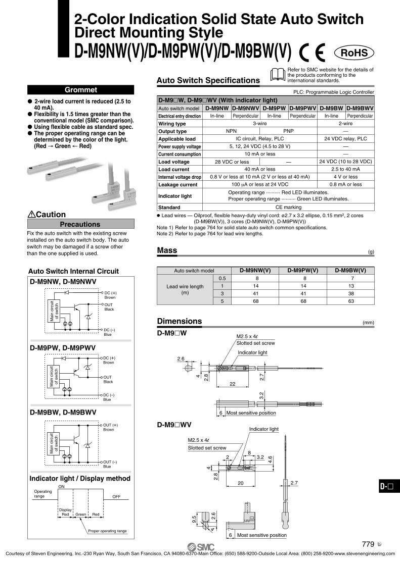
Solid State Auto SwitchDirect Mounting StyleD-M9N(V)/D-M9P(V)/D-M9B(V)
Auto Switch Internal CircuitD-M9N, D-M9NV
D-M9B, D-M9BV
D-M9P, D-M9PV
Auto Switch Specifications
Mass
Auto switch model
0.5
1
3
5
D-M9N(V) 8
14
41
68
D-M9P(V) 8
14
41
68
D-M9B(V) 7
13
38
63
(g)
Lead wire length(m)
Grommet
Auto switch model
Electrical entry direction
Wiring type
Output type
Applicable load
Power supply voltage
Current consumption
Load voltage
Load current
Internal voltage drop
Leakage current
Indicator light
Standard
D-M9NVD-M9N D-M9B D-M9BV
2-wire
—
24 VDC relay, PLC
—
—
24 VDC (10 to 28 VDC)
2.5 to 40 mA
4 V or less
0.8 mA or less
D-M9PVD-M9P
Red LED illuminates when turned ON.
CE marking
3-wire
IC circuit, Relay, PLC
5, 12, 24 VDC (4.5 to 28 V)
10 mA or less
40 mA or less
0.8 V or less at 10 mA (2 V or less at 40 mA)
100 μA or less at 24 VDC
In-line Perpendicular In-line Perpendicular In-line Perpendicular
NPN PNP
28 VDC or less —
D-M9, D-M9V (With indicator light)
Lead wires — Oilproof, flexible heavy-duty vinyl cord: ø2.7 x 3.2 ellipse, 0.15 mm2, 2 cores (D-M9B(V)), 3 cores (D-M9N(V), D-M9P(V))
Note 1) Refer to page 764 for solid state auto switch common specifications.Note 2) Refer to page 764 for lead wire lengths.
Dimensions
D-M9
D-M9V
M2.5 x 4l
2.7
22
2.6
4
2.8
3.2
6
4
2.6
9.5
2.7
4.62
20
M2.5 x 4l
2.8
83.2
4
Indicator lightSlotted set screw
6 Most sensitive position
2-wire load current is reduced (2.5 to 40 mA).
Flexibility is 1.5 times greater than the conventional model (SMC comparison).
Using flexible cable as standard spec.
PrecautionsCaution
(mm)
Fix the auto switch with the existing screw installed on the auto switch body. The auto switch may be damaged if a screw other than the one supplied is used.
Refer to SMC website for the details of the products conforming to the international standards.
PLC: Programmable Logic Controller
DC (+)Brown
OUTBlack
DC (–)Blue
DC (+)Brown
OUTBlack
DC (–)Blue
OUT (+)Brown
OUT (–)Blue
Mai
n ci
rcui
t of
sw
itch
Mai
n ci
rcui
t of
sw
itch
Mai
n ci
rcui
t of
sw
itch
Slotted set screw
Indicator light
Most sensitive position
774
P0764-P0810-E.qxd 08.9.29 4:03 PM Page 774
Courtesy of Steven Engineering, Inc.-230 Ryan Way, South San Francisco, CA 94080-6370-Main Office: (650) 588-9200-Outside Local Area: (800) 258-9200-www.stevenengineering.com

Auto Switch Specifications
Dimensions
Mass
Auto switch model
0.5
3
5
D-Y59B D-Y69B9
50
83
D-Y59A D-Y69A10
53
87
D-Y7P(V)10
53
87
(g)
(mm)
Lead wire length(m)
AB
AB
Auto Switch Internal Circuit
D-Y59A, D-Y69A
D-Y59B, D-Y69B
D-Y7P, D-Y7PV
D-Y59A/D-Y7P/D-Y59B D-Y69A/D-Y7PV/D-Y69B
D-Y5, D-Y6, D-Y7P, D-Y7PV (With indicator light)Auto switch model
Electrical entry direction
Wiring type
Output type
Applicable load
Power supply voltage
Current consumption
Load voltage
Load current
Internal voltage drop
Leakage current
Indicator light
Standard
D-Y59A
In-line
3-wire
NPN
IC circuit, Relay, PLC
5, 12, 24 VDC (4.5 to 28 V)
28 VDC or less
40 mA or less
Red LED illuminates when turned ON.
CE marking
D-Y69A
Perpendicular
D-Y69B
Perpendicular
D-Y7PV
Perpendicular
D-Y59B
In-line
2-wire
—
24 VDC relay, PLC
—
—
24 VDC (10 to 28 VDC)
2.5 to 40 mA
4 V or less
0.8 mA or less at 24 VDC
D-Y7P
In-line
PNP
10 mA or less
—
80 mA or less
0.8 V or less
SM
CS
MC
SM
CS
MC
6.2
5
2.5
29
ø3.
4
12.5
27.3
6.2
5
12.5
8.5
2.5
ø3.4
Most sensitive position
M2.5 x 4l
Slotted set screw
Slotted set screw
Indicator light
Indicator light
Most sensitive position
M2.5 x 4l
Grommet
Using flexible cable as standard spec.
Refer to SMC website for the details of the products conforming to the international standards.
PLC: Programmable Logic Controller
Solid State Auto SwitchDirect Mounting StyleD-Y59 /D-Y69 /D-Y7P(V)
1.5 V or less(0.8 V or less
at 10 mA load current)
• Lead wires — Oilproof, flexible heavy-duty vinyl cord, ø3.4, 0.15 mm2, 3 cores (Brown, Black, Blue), 2 cores (Brown, Blue), 0.5 m
Note 1) Refer to page 764 for solid state auto switch common specifications.Note 2) Refer to page 764 for lead wire lengths.
Mai
n ci
rcui
t of
sw
itch
Mai
n ci
rcui
t of
sw
itch
Mai
n ci
rcui
t of
sw
itch
OUT (+)Brown
OUT (–)Blue
OUTBlack
DC (+)Brown
DC (–)Blue
OUTBlack
DC (+)Brown
DC (–)Blue
100 µA or less at 24 VDC
775
D-
4-4-03-AutoUM.qxd 09.9.30 5:16 PM Page 2
Courtesy of Steven Engineering, Inc.-230 Ryan Way, South San Francisco, CA 94080-6370-Main Office: (650) 588-9200-Outside Local Area: (800) 258-9200-www.stevenengineering.com

Indicator light
ø3.2 mounting hole
8
23
4.6
15
7
Most sensitive position8.5
11
6.2
3.2
ø3.
4
Mass
Dimensions
(g)
(mm)
Auto switch model
0.5
3
5
13
57
92
13
57
92
11
50
81
D-F79W D-F7PW D-J79W
Lead wire length(m)
Auto Switch Internal Circuit
D-F79W
D-J79W
Indicator light/Display method
D-F7PW
GrommetD-F7W, D-J79W (With indicator light)Auto switch model
Wiring type
Output type
Applicable load
Power supply voltage
Current consumption
Load voltage
Load current
Internal voltage drop
Leakage current
Indicator light
Standard
D-F79W
3-wire
NPN
IC circuit, Relay, PLC
5, 12, 24 VDC (4.5 to 28 VDC)
10 mA or less
28 VDC or less
40 mA or less
100 µA or less at 24 VDC
D-J79W
2-wire
—
24 VDC Relay, PLC
—
—
24 VDC (10 to 28 VDC)
5 to 40 mA
4 V or less
0.8 mA or less at 24 VDC
D-F7PW
PNP
—
80 mA or less
0.8 V or less1.5 V or less(0.8 V or less
at 10 mA load current)
CE marking
Auto Switch SpecificationsRefer to SMC website for the details of the products conforming to the international standards.
PLC: Programmable Logic Controller
2-Color Indication Solid State Auto SwitchRail Mounting StyleD-F79W/D-F7PW/D-J79W
The proper operating range can be determined by the color of the light.(Red → Green ← Red)
Operating range
IndicationGreenRed Red
Mai
n ci
rcui
t of
sw
itch
Mai
n ci
rcui
t of
sw
itch
OUT (+)Brown
OUT (–)Blue
OUTBlack
DC (+)Brown
DC (–)Blue
• Lead wires — Oilproof heavy-duty vinyl cord, ø3.4, 0.2 mm2, 3 cores (Brown, Black, Blue), 2 cores (Brown, Blue), 0.5 m
Note 1) Refer to page 764 for solid state auto switch common specifications.Note 2) Refer to page 764 for lead wire lengths.
Operating range .......... Red LED illuminates.Proper operating range .......... Green LED illuminates.
Proper operating range
OUTBlack
Mai
n ci
rcui
t of
sw
itch
DC (+)Brown
DC (–)Blue
776
4-4-03-AutoSw-UM.qxd 10.3.30 1:08 PM Page 1
Courtesy of Steven Engineering, Inc.-230 Ryan Way, South San Francisco, CA 94080-6370-Main Office: (650) 588-9200-Outside Local Area: (800) 258-9200-www.stevenengineering.com

Mass
Dimensions
(g)
(mm)
Auto switch model
0.5
3
5
13
57
92
11
50
81
D-F7NWV D-F7BWV
Lead wire length(m)
Auto Switch Internal Circuit
D-F7NWV
Indicator light/Display method
D-F7BWV
GrommetElectrical entry: Perpendicular D-F7WV (With indicator light)
Auto switch model
Wiring type
Output type
Applicable load
Power supply voltage
Current consumption
Load voltage
Load current
Internal voltage drop
Leakage current
Indicator light
Standard
D-F7BWV
2-wire
—
24 VDC Relay, PLC
—
—
24 VDC (10 to 28 VDC)
5 to 40 mA
4 V or less
0.8 mA or less at 24 VDC
D-F7NWV
3-wire
NPN
IC circuit, Relay, PLC
5, 12, 24 VDC (4.5 to 28 VDC)
10 mA or less
28 VDC or less
40 mA or less
100 µA or less at 24 VD
1.5 V or less(0.8 V or less
at 10 mA load current)
CE marking
Auto Switch SpecificationsRefer to SMC website for the details of the products conforming to the international standards.
PLC: Programmable Logic Controller
ø3.2 mounting hole
Indicator light
Most sensitive position
2-Color Indication Solid State Auto SwitchRail Mounting StyleD-F7NWV/D-F7BWV
The proper operating range can be determined by the color of the light.(Red → Green ← Red)
• Lead wires — Oilproof heavy-duty vinyl cord, ø3.4, 0.2 mm2, 3 cores (Brown, Black, Blue), 2 cores (Brown, Blue), 0.5 m
Note 1) Refer to page 764 for solid state auto switch common specifications.Note 2) Refer to page 764 for lead wire lengths.
Operating range
IndicationGreenRed Red
Mai
n ci
rcui
t of
sw
itch
OUT (+)Brown
OUT (–)Blue
OUTBlack
DC (+)Brown
DC (–)Blue
Mai
n ci
rcui
t of
sw
itch
Proper operating range
Operating range .......... Red LED illuminates.Proper operating range .......... Green LED illuminates.
777
D-
4-4-03-AutoSw-UM.qxd 09.11.30 10:00 AM Page 2
Courtesy of Steven Engineering, Inc.-230 Ryan Way, South San Francisco, CA 94080-6370-Main Office: (650) 588-9200-Outside Local Area: (800) 258-9200-www.stevenengineering.com

Auto Switch Internal Circuit
D-Y7NW, Y7NWV
D-Y7BW, Y7BWV
D-Y7PW, Y7PWV
Dimensions
Grommet
Indicator light/Display method
D-Y7W, D-Y7WV (With indicator light)Auto switch model
Electrical entry direction
Wiring type
Output type
Applicable load
Power supply voltage
Current consumption
Load voltage
Load current
Internal voltage drop
Leakage current
Indicator light
Standard
D-Y7NW
In-line
3-wire
NPN
IC circuit, Relay, PLC
5, 12, 24 VDC (4.5 to 28 VDC)
10 mA or less
28 VDC or less
40 mA or less
100 µA or less at 24 VDC
D-Y7NWV
Perpendicular
D-Y7BWV
Perpendicular
D-Y7PWV
Perpendicular
D-Y7BW
In-line
2-wire
—
24 VDC relay, PLC
—
—
24 VDC (10 to 28 VDC)
2.5 to 40 mA
4 V or less
0.8 mA or less at 24 VDC
D-Y7PW
In-line
PNP
—
80 mA or less
0.8 V or less1.5 V or less(0.8 V or less
at 10 mA load current)
Mass
Auto switch model
0.5
3
5
D-Y7NW(V) D-Y7PW(V) D-Y7BW(V)11
54
88
11
54
88
11
54
88
(g)
(mm)
Lead wire length(m)
D-Y7W
D-Y7WV
M2.5 x 4l
Slotted set screw
Indicator light
Most sensitive position
M2.5 x 4l
Slotted set screw
Indicator light
SM
CS
MC
6.2
5
2.5
29
ø3.
4
12.5
27.3
6.2
5
12.5
8.5
2.5
ø3.4
Most sensitive position
CE marking
Auto Switch SpecificationsRefer to SMC website for the details of the products conforming to the international standards.
PLC: Programmable Logic Controller
2-Color Indication Solid State Auto SwitchDirect Mounting StyleD-Y7NW(V)/D-Y7PW(V)/D-Y7BW(V)
Operating range
IndicationGreenRed Red
Proper operating range
Mai
n ci
rcui
t of
sw
itch
Mai
n ci
rcui
t of
sw
itch
Mai
n ci
rcui
t of
sw
itch OUT
Black
DC (+)Brown
DC (–)Blue
OUTBlack
DC (+)Brown
DC (–)Blue
OUT (+)Brown
OUT (–)Blue
• Lead wires — Oilproof, flexible heavy-duty vinyl cord, ø3.4, 0.15 mm2, 3 cores (Brown, Black, Blue), 2 cores (Brown, Blue), 0.5 m
Note 1) Refer to page 764 for solid state auto switch common specifications.Note 2) Refer to page 764 for lead wire lengths.
Operating range .......... Red LED illuminates.Proper operating range .......... Green LED illuminates.
The proper operating range can be determined by the color of the light. (Red → Green ← Red)
Using flexible cable as standard spec.
778
4-4-03-AutoSw-UM.qxd 09.11.30 10:00 AM Page 3
Courtesy of Steven Engineering, Inc.-230 Ryan Way, South San Francisco, CA 94080-6370-Main Office: (650) 588-9200-Outside Local Area: (800) 258-9200-www.stevenengineering.com
Mass (g)
(mm)Dimensions
Auto switch model
0.5
1
3
5
D-M9NW(V)8
14
41
68
D-M9PW(V)8
14
41
68
D-M9BW(V)7
13
38
63
Lead wire length(m)
Grommet
Auto switch model
Electrical entry direction
Wiring type
Output type
Applicable load
Power supply voltage
Current consumption
Load voltage
Load current
Internal voltage drop
Leakage current
Indicator light
Standard
D-M9NWVD-M9NW D-M9BW D-M9BWV
2-wire
—
24 VDC relay, PLC
—
—
24 VDC (10 to 28 VDC)
2.5 to 40 mA
4 V or less
0.8 mA or less
D-M9PWVD-M9PW
Operating range .......... Red LED illuminates.Proper operating range .......... Green LED illuminates.
3-wire
IC circuit, Relay, PLC
5, 12, 24 VDC (4.5 to 28 V)
10 mA or less
40 mA or less
0.8 V or less at 10 mA (2 V or less at 40 mA)
100 µA or less at 24 VDC
CE marking
In-line Perpendicular In-line Perpendicular In-line Perpendicular
NPN PNP
28 VDC or less —
D-M9W, D-M9WV (With indicator light)
Lead wires — Oilproof, flexible heavy-duty vinyl cord: ø2.7 x 3.2 ellipse, 0.15 mm2, 2 cores(D-M9BW(V)), 3 cores (D-M9NW(V), D-M9PW(V))
Note 1) Refer to page 764 for solid state auto switch common specifications.Note 2) Refer to page 764 for lead wire lengths.
2-wire load current is reduced (2.5 to 40 mA).
Flexibility is 1.5 times greater than the conventional model (SMC comparison).
Using flexible cable as standard spec. The proper operating range can be
determined by the color of the light. (Red → Green ← Red)
D-M9NW, D-M9NWV
D-M9BW, D-M9BWV
D-M9PW, D-M9PWV
Indicator light / Display method
Auto Switch Internal Circuit
D-M9W
D-M9WV
M2.5 x 4l
Slotted set screw
Indicator light
2.7
22
2.6
4
2.8
3.2
6 Most sensitive position
4
2.6
9.5
M2.5 x 4l
Indicator light
Slotted set screw
2.8
4.6
4
20
28
3.2
6 Most sensitive position
2.7
PrecautionsCaution
Fix the auto switch with the existing screw installed on the auto switch body. The auto switch may be damaged if a screw other than the one supplied is used.
Auto Switch SpecificationsRefer to SMC website for the details of the products conforming to the international standards.
PLC: Programmable Logic Controller
2-Color Indication Solid State Auto SwitchDirect Mounting StyleD-M9NW(V)/D-M9PW(V)/D-M9BW(V)
OUTBlack
DC (+)Brown
DC (–)Blue
DC (+)Brown
OUTBlack
DC (–)Blue
OUT (+)Brown
OUT (–)Blue
ON
OFF
Mai
n ci
rcui
t of
sw
itch
Mai
n ci
rcui
t of
sw
itch
Mai
n ci
rcui
t of
sw
itch
Proper operating range
DisplayRed Green Red
Operatingrange
RoHS
779
D-
RoHS-SW-4.qxd 10.7.26 4:52 PM Page 1
Courtesy of Steven Engineering, Inc.-230 Ryan Way, South San Francisco, CA 94080-6370-Main Office: (650) 588-9200-Outside Local Area: (800) 258-9200-www.stevenengineering.com
Mass
Dimensions
(g)
(mm)
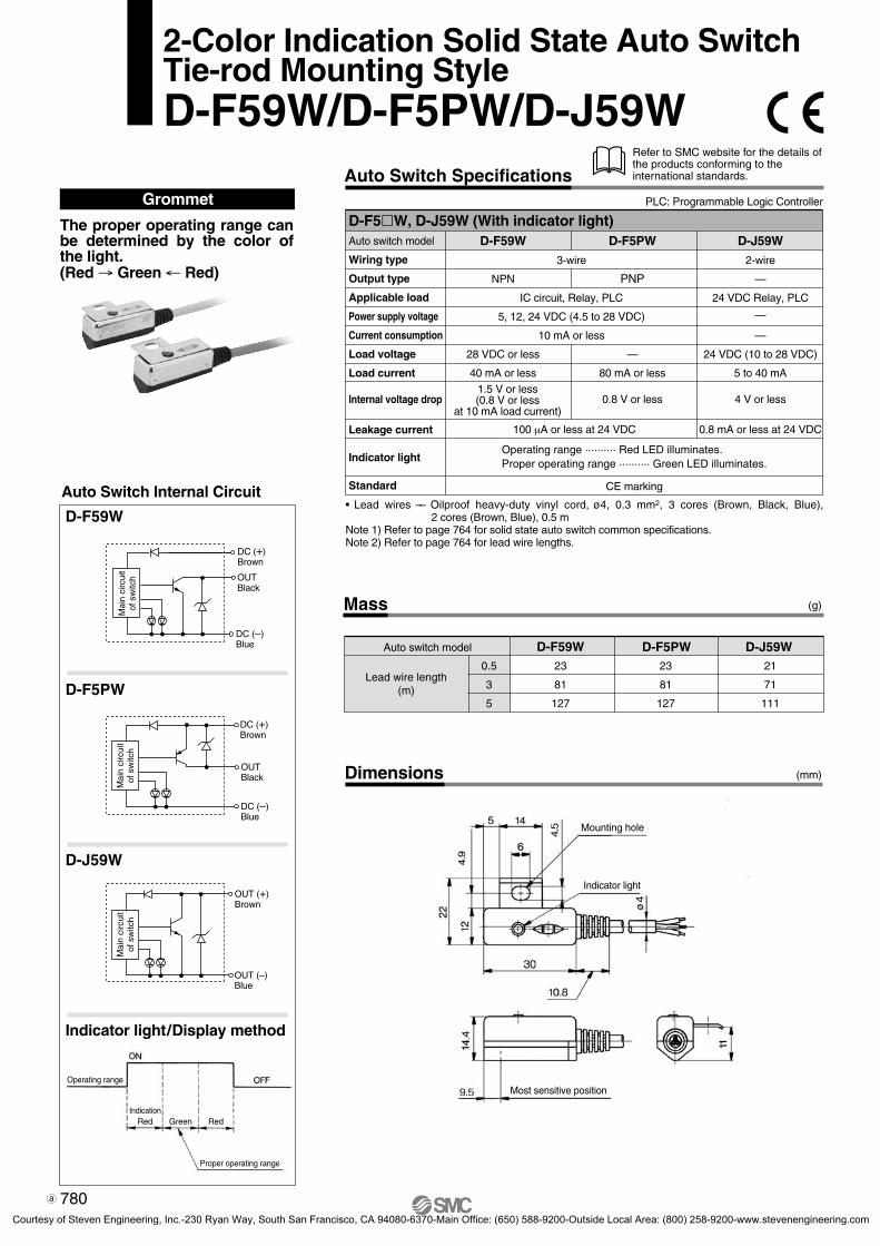
2-Color Indication Solid State Auto SwitchTie-rod Mounting StyleD-F59W/D-F5PW/D-J59W
Auto switch model
0.5
3
5
23
81
127
23
81
127
21
71
111
D-F59W D-F5PW D-J59W
Lead wire length(m)
Auto Switch Internal Circuit
D-F59W
D-J59W
Indicator light/Display method
D-F5PW
GrommetD-F5W, D-J59W (With indicator light)Auto switch model
Wiring type
Output type
Applicable load
Power supply voltage
Current consumption
Load voltage
Load current
Internal voltage drop
Leakage current
Indicator light
Standard
D-F59W
3-wire
NPN
IC circuit, Relay, PLC
5, 12, 24 VDC (4.5 to 28 VDC)
10 mA or less
28 VDC or less
40 mA or less
100 µA or less at 24 VDC
D-J59W
2-wire
—
24 VDC Relay, PLC
—
—
24 VDC (10 to 28 VDC)
5 to 40 mA
4 V or less
0.8 mA or less at 24 VDC
D-F5PW
PNP
—
80 mA or less
0.8 V or less1.5 V or less(0.8 V or less
at 10 mA load current)
Auto Switch SpecificationsRefer to SMC website for the details of the products conforming to the international standards.
PLC: Programmable Logic Controller
CE marking
The proper operating range can be determined by the color of the light.(Red → Green ← Red)
• Lead wires –– Oilproof heavy-duty vinyl cord, ø4, 0.3 mm2, 3 cores (Brown, Black, Blue), 2 cores (Brown, Blue), 0.5 m
Note 1) Refer to page 764 for solid state auto switch common specifications.Note 2) Refer to page 764 for lead wire lengths.
Operating range
IndicationGreenRed Red
Mai
n ci
rcui
t of
sw
itch
Mai
n ci
rcui
t of
sw
itch
OUT (+)Brown
OUT (–)Blue
OUTBlack
DC (+)Brown
DC (–)Blue
OUTBlack
DC (+)Brown
DC (–)Blue
Mai
n ci
rcui
t of
sw
itch
Mounting hole
Indicator light
Most sensitive position
Proper operating range
Operating range .......... Red LED illuminates.Proper operating range .......... Green LED illuminates.
780
4-4-03-AutoSw-UM.qxd 09.11.30 10:00 AM Page 5
Courtesy of Steven Engineering, Inc.-230 Ryan Way, South San Francisco, CA 94080-6370-Main Office: (650) 588-9200-Outside Local Area: (800) 258-9200-www.stevenengineering.com

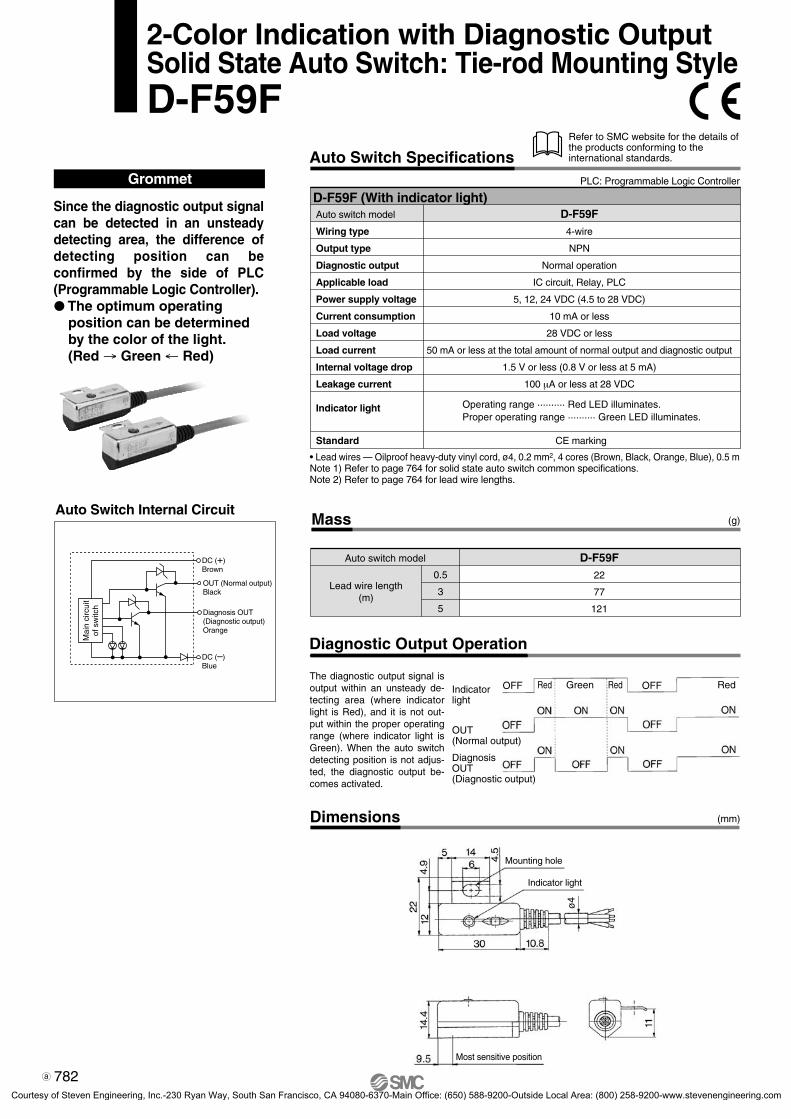
2-Color Indication with Diagnostic OutputSolid State Auto Switch: Rail Mounting StyleD-F79F
Grommet
Auto Switch Internal Circuit
Since the diagnostic output signal can be detected in an unsteady detecting area, the difference of detecting position can be confirmed by the side of PLC (Programmable Logic Controller). The optimum operating
position can be determined by the color of the light. (Red → Green ← Red)
OUT (Normal output)Black
DC (+)Brown
DC (–)Blue
Diagnosis OUT(Diagnostic output)Orange
Mai
n ci
rcui
t of
sw
itch
Auto Switch SpecificationsRefer to SMC website for the details of the products conforming to the international standards.
D-F79F (With indicator light)Auto switch model
Wiring type
Output type
Diagnostic output type
Applicable load
Power supply voltage
Current consumption
Load voltage
Load current
Internal voltage drop
Leakage current
Indicator light
Standard
D-F79F
4-wire
NPN
Normal operation
IC circuit, Relay, PLC
5, 12, 24 VDC (4.5 to 28 VDC)
10 mA or less
28 VDC or less
50 mA or less at the total amount of normal output and diagnostic output
1.5 V or less (0.8 V or less at 5 mA)
100 µA or less at 24 VDC
Operating range .......... Red LED illuminates.Proper operating range .......... Green LED illuminates.
Lead wires — Oilproof heavy-duty vinyl cord: ø3.4, 0.2 mm2 x 4 cores (Brown, Black, Orange, Blue), 0.5 mNote 1) Refer to page 764 for solid state auto switch common specifications.Note 2) Refer to page 764 for lead wire lengths.
CE marking
PLC: Programmable Logic Controller
Mass
Diagnostic Output Operation
Dimensions
Auto switch model
0.5
3
5
13
56
90
D-F79F
(g)
(mm)
Lead wire length(m)
The diagnostic output signal is output within an unsteady de-tecting area (where indicator light is Red), and it is not out-put within the proper operating range (where indicator light is Green). When the auto switch detecting position is not adjus-ted, the diagnostic output be-comes activated.
Indicator light
OUT(Normal output)
Diagnosis OUT(Diagnostic output)
Red Green Red Red
Indicator light
Most sensitive position
ø3.
4
ø3.2 Mounting hole
781
D-
4-4-03-AutoSw-UM.qxd 09.11.30 10:00 AM Page 6
Courtesy of Steven Engineering, Inc.-230 Ryan Way, South San Francisco, CA 94080-6370-Main Office: (650) 588-9200-Outside Local Area: (800) 258-9200-www.stevenengineering.com
Auto Switch Internal Circuit
Auto Switch Specifications
Diagnostic Output Operation
Dimensions
Grommet
Mass
Auto switch model
0.5
3
5
D-F59F22
77
121
(g)
(mm)
Lead wire length(m)
Since the diagnostic output signal can be detected in an unsteady detecting area, the difference of detecting position can be confirmed by the side of PLC (Programmable Logic Controller). The optimum operating
position can be determined by the color of the light. (Red → Green ← Red)
D-F59F (With indicator light)Auto switch model
Wiring type
Output type
Diagnostic output
Applicable load
Power supply voltage
Current consumption
Load voltage
Load current
Internal voltage drop
Leakage current
Indicator light
D-F59F
4-wire
NPN
Normal operation
IC circuit, Relay, PLC
5, 12, 24 VDC (4.5 to 28 VDC)
10 mA or less
28 VDC or less
50 mA or less at the total amount of normal output and diagnostic output
1.5 V or less (0.8 V or less at 5 mA)
100 µA or less at 28 VDC
2-Color Indication with Diagnostic OutputSolid State Auto Switch: Tie-rod Mounting StyleD-F59F
Standard CE marking
Refer to SMC website for the details of the products conforming to the international standards.
PLC: Programmable Logic Controller
The diagnostic output signal is output within an unsteady de-tecting area (where indicator light is Red), and it is not out-put within the proper operating range (where indicator light is Green). When the auto switch detecting position is not adjus-ted, the diagnostic output be-comes activated.
Indicator light
OUT(Normal output)
Diagnosis OUT(Diagnostic output)
Red GreenOFF OFFRed Red
ø4
Indicator light
Mounting hole
Most sensitive position
• Lead wires — Oilproof heavy-duty vinyl cord, ø4, 0.2 mm2, 4 cores (Brown, Black, Orange, Blue), 0.5 mNote 1) Refer to page 764 for solid state auto switch common specifications.Note 2) Refer to page 764 for lead wire lengths.
OUT (Normal output)Black
DC (+)Brown
DC (–)Blue
Diagnosis OUT(Diagnostic output)Orange
Mai
n ci
rcui
t of
sw
itch
Operating range .......... Red LED illuminates.Proper operating range .......... Green LED illuminates.
782
4-4-03-AutoSw-UM.qxd 09.11.30 10:00 AM Page 7
Courtesy of Steven Engineering, Inc.-230 Ryan Way, South San Francisco, CA 94080-6370-Main Office: (650) 588-9200-Outside Local Area: (800) 258-9200-www.stevenengineering.com

8.5
15
6.2
3.2
11
23
SM
C
8
7
15
ø3.4
ø3.2 mounting hole
Most sensitive position
Indicator light
Indicator light
ø3.2 mounting hole
Most sensitive position
Auto Switch Internal Circuit
Auto Switch Specifications
Dimensions
Water Resistant 2-Color IndicationSolid State Auto Switch: Rail Mounting StyleD-F7BA(V)L
Grommet
Water (coolant) resistant type The proper operating range
can be determined by the color of the light. (Red → Green ← Red)
PrecautionsCaution
Please consult with SMC if using coolant liquid other than water based solution.
Indicator light/Display method
D-F7BA(V)L (With indicator light)Auto switch model
Electrical entry direction
Wiring type
Output type
Applicable load
Power supply voltage
Current consumption
Load voltage
Load current
Internal voltage drop
Leakage current
Indicator light
2-wire
—
24 VDC Relay, PLC
—
—
24 VDC (10 to 28 VDC)
5 to 40 mA
4 V or less
0.8 mA or less at 24 VDC
D-F7BAVL
Perpendicular
D-F7BAL
In-line
D-F7BAL
D-F7BAVL
Mass
Auto switch model
0.5
3
5
D-F7BA—
50
81
D-F7BAV—
50
81
(g)
(mm)
Lead wire length(m)
Standard CE marking
Refer to SMC website for the details of the products conforming to the international standards.
PLC: Programmable Logic Controller
Operating range
IndicationGreenRed Red
Mai
n ci
rcui
t of
sw
itch
OUT (+)Brown
OUT (–)Blue
• Lead wires — Oilproof heavy-duty vinyl cord, ø3.4, 0.2 mm2, 2 cores (Brown, Blue), 3 m (Standard)Note 1) Refer to page 764 for solid state auto switch common specifications.Note 2) Refer to page 764 for lead wire lengths.
Proper operating range
Operating range .......... Red LED illuminates.Proper operating range .......... Green LED illuminates.
783
D-
4-4-03-AutoSw-UM.qxd 09.11.30 10:00 AM Page 8
Courtesy of Steven Engineering, Inc.-230 Ryan Way, South San Francisco, CA 94080-6370-Main Office: (650) 588-9200-Outside Local Area: (800) 258-9200-www.stevenengineering.com
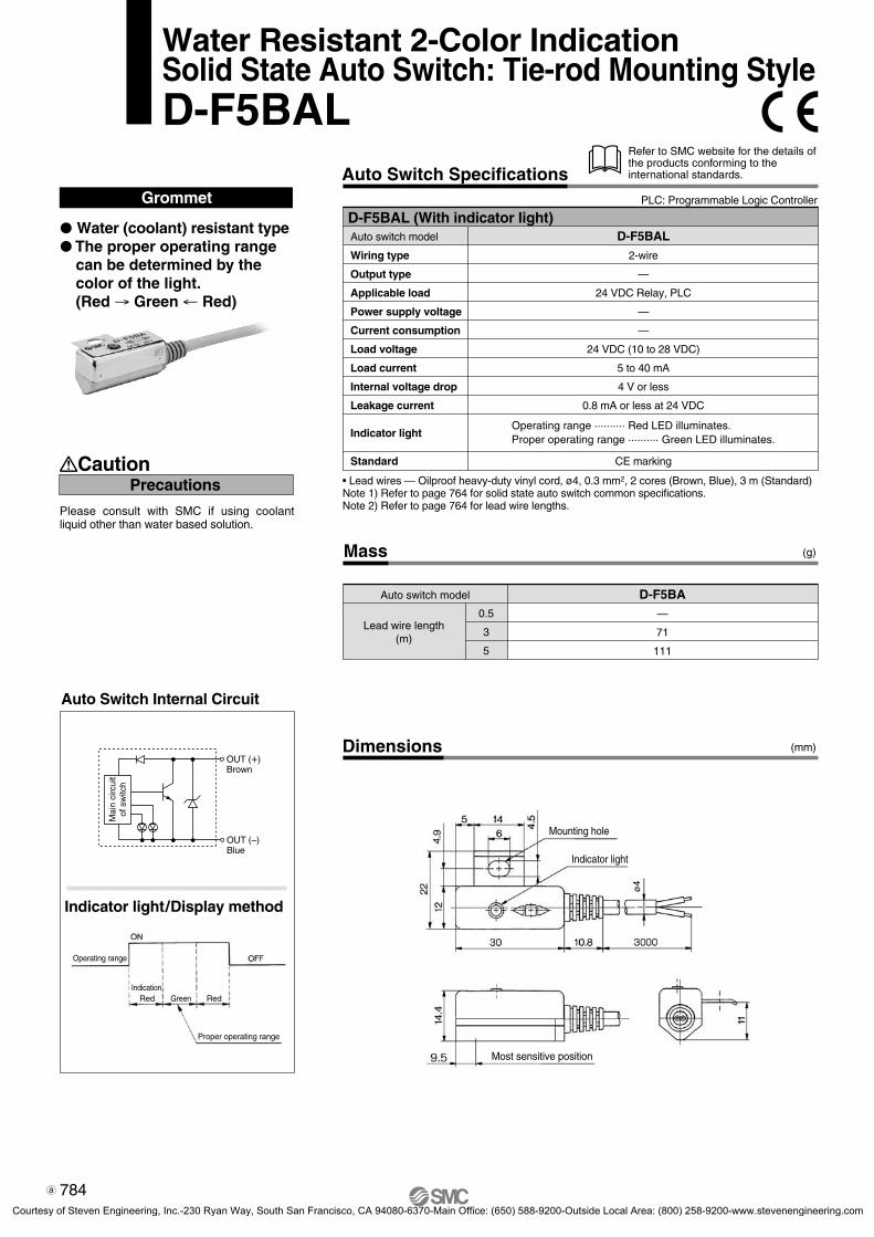
Mass
Auto switch model
0.5
3
5
(g)
(mm)
Lead wire length(m)
D-F5BA—
71
111
Auto Switch Internal Circuit
Auto Switch Specifications
Dimensions
Water Resistant 2-Color IndicationSolid State Auto Switch: Tie-rod Mounting StyleD-F5BAL
Grommet
ø4
Caution
Please consult with SMC if using coolant liquid other than water based solution.
Indicator light/Display method
Auto switch model
Wiring type
Output type
Applicable load
Power supply voltage
Current consumption
Load voltage
Load current
Internal voltage drop
Leakage current
Indicator light
D-F5BAL
2-wire
—
24 VDC Relay, PLC
—
—
24 VDC (10 to 28 VDC)
5 to 40 mA
4 V or less
0.8 mA or less at 24 VDC
D-F5BAL (With indicator light)
Precautions
Standard CE marking
Refer to SMC website for the details of the products conforming to the international standards.
PLC: Programmable Logic Controller
Water (coolant) resistant type The proper operating range
can be determined by the color of the light. (Red → Green ← Red)
• Lead wires — Oilproof heavy-duty vinyl cord, ø4, 0.3 mm2, 2 cores (Brown, Blue), 3 m (Standard)Note 1) Refer to page 764 for solid state auto switch common specifications.Note 2) Refer to page 764 for lead wire lengths.
Mai
n ci
rcui
t of
sw
itch
OUT (+)Brown
OUT (–)Blue
Operating range
IndicationGreenRed Red
Mounting hole
Most sensitive position
Indicator light
Proper operating range
Operating range .......... Red LED illuminates.Proper operating range .......... Green LED illuminates.
784
4-4-03-AutoSw-UM.qxd 09.11.30 10:00 AM Page 9
Courtesy of Steven Engineering, Inc.-230 Ryan Way, South San Francisco, CA 94080-6370-Main Office: (650) 588-9200-Outside Local Area: (800) 258-9200-www.stevenengineering.com

5
12.5 Most sensitive position
Production lot
24 VDC 5.2
2.5
6.2
35
Indicator light
Slotted set screw
M2.5 x 4l
D-Y7BA
SM
C
Auto Switch Internal Circuit
Auto Switch Specifications
Dimensions
Grommet
Mass
Auto switch model
0.5
3
5
D-Y7BA—
54
88
(g)
Lead wire length(m)
Caution
Please consult with SMC if using coolant liquid other than water based solution.Detection characteristics are the same as D-Y5 and D-Y7W, but the detection area length is different.
Indicator light/Display method
D-Y7BAL (With indicator light)Auto switch model
Wiring type
Applicable load
Load voltage
Load current
Internal voltage drop
Leakage current
Indicator light
Standard
D-Y7BAL
2-wire
24 VDC Relay, PLC
24 VDC (10 to 28 VDC)
2.5 to 40 mA or less
4 V or less
0.8 mA or less at 24 VDC
CE marking
Precautions
(mm)
Refer to SMC website for the details of the products conforming to the international standards.
PLC: Programmable Logic Controller
Water Resistant 2-Color IndicationSolid State Auto Switch: Direct Mounting StyleD-Y7BAL
Water (coolant) resistant type Uses a flexible cord as
standard. The proper operating range
can be determined by the color of the light. (Red → Green ← Red)
• Lead wires — Oilproof, flexible heavy-duty vinyl cord, ø3.4, 0.15 mm2, 2 cores (Brown, Blue), 3 m (Standard)
Note 1) Refer to page 764 for solid state auto switch common specifications.Note 2) Refer to page 764 for lead wire lengths.
Operating range
IndicationGreenRed Red
Mai
n ci
rcui
t of
sw
itch
OUT (+)Brown
OUT (–)Blue
Operating range .......... Red LED illuminates.Proper operating range .......... Green LED illuminates.
Proper operating range
785
D-
4-4-03-AutoSw-UM.qxd 09.11.30 10:00 AM Page 10
Courtesy of Steven Engineering, Inc.-230 Ryan Way, South San Francisco, CA 94080-6370-Main Office: (650) 588-9200-Outside Local Area: (800) 258-9200-www.stevenengineering.com

Mass (g)
Auto switch model
0.5
1
3
5
D-M9NA(V)8
14
41
68
D-M9PA(V)8
14
41
68
D-M9BA(V)7
13
38
63
Lead wire length(m)
Grommet
Auto switch model
Electrical entry direction
Wiring type
Output type
Applicable load
Power supply voltage
Current consumption
Load voltage
Load current
Internal voltage drop
Leakage current
Indicator light
Standard
D-M9NAVD-M9NA D-M9BA D-M9BAV
2-wire
—
24 VDC relay, PLC
—
—
24 VDC (10 to 28 VDC)
2.5 to 40 mA
4 V or less
0.8 mA or less
D-M9PAVD-M9PA
3-wire
IC circuit, Relay, PLC
5, 12, 24 VDC (4.5 to 28 V)
10 mA or less
40 mA or less
0.8 V or less at 10 mA (2 V or less at 40 mA)
100 µA or less at 24 VDC
In-line Perpendicular In-line Perpendicular In-line Perpendicular
NPN PNP
CE marking
28 VDC or less —
D-M9A(V) (With indicator light)
Lead wires — Oilproof, flexible heavy-duty vinyl cord: ø2.7 x 3.2 ellipse, 0.15 mm2, 2 cores(D-M9BA(V)), 3 cores (D-M9NA(V), D-M9PA(V))
Note 1) Refer to page 764 for solid state auto switch common specifications.Note 2) Refer to page 764 for lead wire lengths.
Water (coolant) resistant type 2-wire load current is reduced (2.5 to
40 mA). The proper operating range can be
determined by the color of the light. (Red → Green ← Red)
Using flexible cable as standard spec.
D-M9NA, D-M9NAV
D-M9BA, D-M9BAV
D-M9PA, D-M9PAV
Indicator light/Display method
Auto Switch Internal Circuit
PrecautionsCaution
2.7
6
2.6
9.3
Most sensitive position
4
SMC
22
3.2
4.6
2.8
4
28
M2.5 x 4l
Slotted set screwIndicator light
4
0.2
3
SMC4
2.8
24 2.7
Indicator light
M2.5 x 4l
Slotted set screw
Dimensions
D-M9A
D-M9AV
(mm)
6
3.2
Most sensitive position
Auto Switch SpecificationsPLC: Programmable Logic Controller
Water Resistant 2-Color IndicationSolid State Auto Switch: Direct Mounting StyleD-M9NA(V)/D-M9PA(V)/D-M9BA(V)
Fix the auto switch with the existing screw installed on the auto switch body. The auto switch may be damaged if a screw other than the one supplied is used.
OUTBlack
DC (+)Brown
DC (–)Blue
DC (+)Brown
OUTBlack
DC (–)Blue
OUT (+)Brown
OUT (–)Blue
ON
OFFOperatingrange
Mai
n ci
rcui
t of
sw
itch
Mai
n ci
rcui
t of
sw
itch
Mai
n ci
rcui
t of
sw
itch
DisplayRed Green Red
Proper operating range
Operating range .......... Red LED illuminates.Proper operating range .......... Green LED illuminates.
RoHS
786
RoHS-SW-4.qxd 10.7.26 4:52 PM Page 2
Courtesy of Steven Engineering, Inc.-230 Ryan Way, South San Francisco, CA 94080-6370-Main Office: (650) 588-9200-Outside Local Area: (800) 258-9200-www.stevenengineering.com

Auto Switch Internal Circuit
Dimensions
Grommet
Mass
Auto switch model
0.5
3
5
D-F7NT—
57
92
(g)
(mm)
Lead wire length(m)
With built-in OFF-delay timer (approx. 200 ms)
Easy intermediate detection
Timer Operation
D-F7NTL (With indicator light)Auto switch model
Wiring type
Output type
Output operation
Operating time
Off-delay time
Applicable load
Power supply voltage
Current consumption
Load voltage
Load current
Internal voltage drop
Leakage current
Indicator light
Standard
D-F7NTL3-wire
NPN
Off-delay
1 ms or less
200 ± 50 ms
IC circuit, Relay, PLC
5, 12, 24 VDC (4.5 to 28 VDC)
10 mA or less
28 VDC or less
40 mA or less
1.5 V or less (0.8 V or less at 10 mA)
100 μA or less at 24 VDC
Red LED illuminates when turned ON.
CE marking
Auto Switch SpecificationsRefer to SMC website for the details of the products conforming to the international standards.
PLC: Programmable Logic Controller
ø3.
4
ø3.2 mounting hole
Indicator light
Most sensitive position
• Lead wires — Oilproof heavy-duty vinyl cord, ø3.4, 0.2 mm2, 3 cores (Brown, Black, Blue), 3 m (Standard)
Note 1) Refer to page 764 for solid state auto switch common specifications.Note 2) Refer to page 764 for lead wire lengths.
Detection of intermediate positioning for high-speed cylinderDetecting point dispersion occurs due to response time of PLC (sequencer); e.g. scanning.
Ex.) Cylinder speed — 1000 mm/sec.PLC response time — 0.1 sec.Detecting point dispersion — Within 100 mm (= 1000 mm/sec. x 0.1 sec.)
Take PLC response time into considera-tion when using.
Switch detecting time
Switch output ON time
PLC response time
Switch operating range (mm)Cylinder speed (mm/s)
Mai
n ci
rcui
t of
sw
itch
OUTBlack
DC (+)Brown
DC (–)Blue
Solid State Auto Switch with TimerRail Mounting StyleD-F7NTL
787
D-
P0764-P0810-E.qxd 08.9.29 4:03 PM Page 787
Courtesy of Steven Engineering, Inc.-230 Ryan Way, South San Francisco, CA 94080-6370-Main Office: (650) 588-9200-Outside Local Area: (800) 258-9200-www.stevenengineering.com
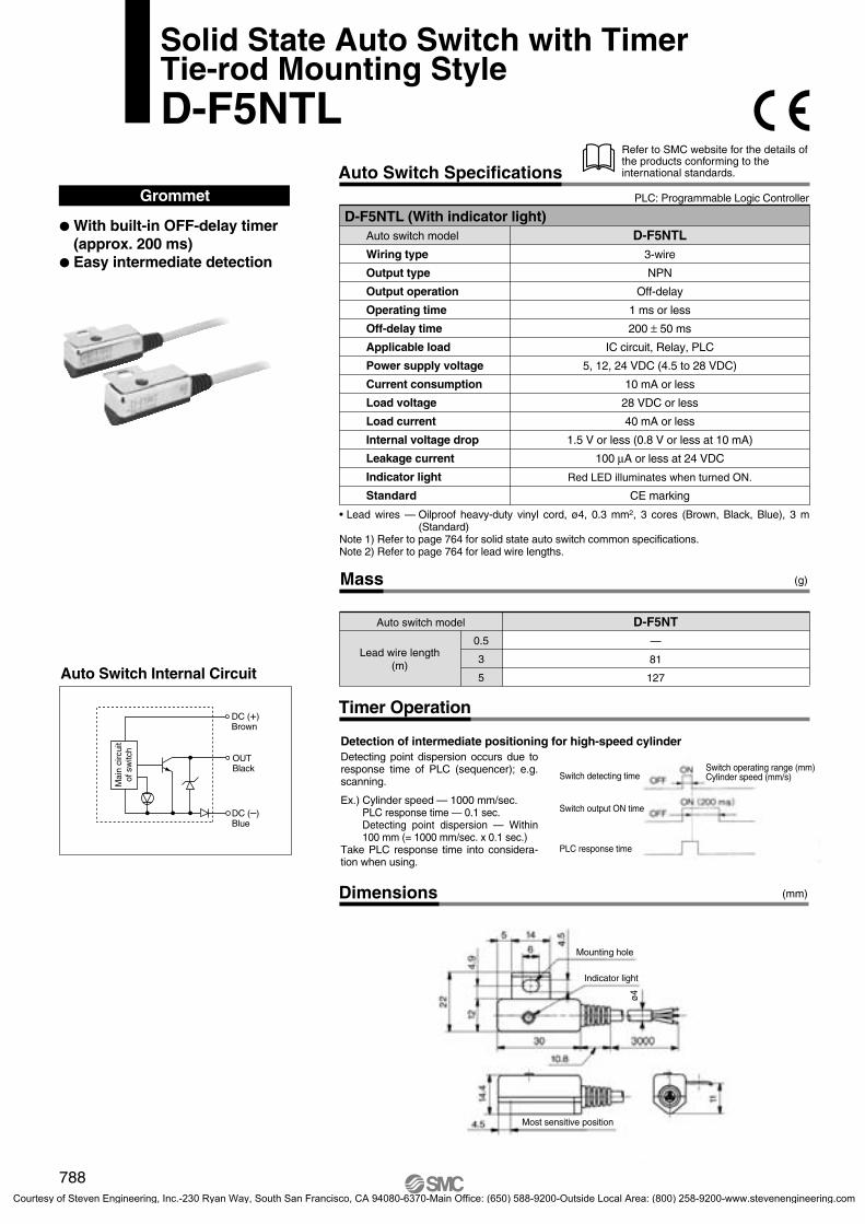
Auto Switch Internal Circuit
Dimensions
Grommet
Timer Operation
D-F5NTL (With indicator light)Auto switch model
Wiring type
Output type
Output operation
Operating time
Off-delay time
Applicable load
Power supply voltage
Current consumption
Load voltage
Load current
Internal voltage drop
Leakage current
Indicator light
Standard
D-F5NTL3-wire
NPN
Off-delay
1 ms or less
200 ± 50 ms
IC circuit, Relay, PLC
5, 12, 24 VDC (4.5 to 28 VDC)
10 mA or less
28 VDC or less
40 mA or less
1.5 V or less (0.8 V or less at 10 mA)
100 μA or less at 24 VDC
Red LED illuminates when turned ON.
CE marking
Mass
Auto switch model
0.5
3
5
(g)
(mm)
Lead wire length(m)
D-F5NT—
81
127
Auto Switch SpecificationsRefer to SMC website for the details of the products conforming to the international standards.
PLC: Programmable Logic Controller
Solid State Auto Switch with TimerTie-rod Mounting StyleD-F5NTL
With built-in OFF-delay timer (approx. 200 ms)
Easy intermediate detection
Mai
n ci
rcui
t of
sw
itch
OUTBlack
DC (+)Brown
DC (–)Blue
Detection of intermediate positioning for high-speed cylinderDetecting point dispersion occurs due to response time of PLC (sequencer); e.g. scanning.
Ex.) Cylinder speed — 1000 mm/sec.PLC response time — 0.1 sec.Detecting point dispersion — Within 100 mm (= 1000 mm/sec. x 0.1 sec.)
Take PLC response time into considera-tion when using.
ø4
Switch detecting time
Switch output ON time
PLC response time
Switch operating range (mm)Cylinder speed (mm/s)
Indicator light
Mounting hole
Most sensitive position
• Lead wires — Oilproof heavy-duty vinyl cord, ø4, 0.3 mm2, 3 cores (Brown, Black, Blue), 3 m (Standard)
Note 1) Refer to page 764 for solid state auto switch common specifications.Note 2) Refer to page 764 for lead wire lengths.
788
P0764-P0810-E.qxd 08.9.29 4:03 PM Page 788
Courtesy of Steven Engineering, Inc.-230 Ryan Way, South San Francisco, CA 94080-6370-Main Office: (650) 588-9200-Outside Local Area: (800) 258-9200-www.stevenengineering.com

Examples
To judge heightof a work piece
To confirm depth of the machined hole
OUT1
OUT2
0.50.5 mmMinimum width to detect
With one switch, various sized work pieces can be
detected by the difference of more than 0.5 mm.
∗ From 0.5 mm to detectable width dependant
on applied actuator.
OUT1 Trimmer OUT2 Trimmer
OUT1 and OUT2 areadjustable separately.
Operating range of sensor (LED of sensor is on.)
OUT1 Detecting rangeOutput ON = Green LED is on.
Adjustable by trimmer
Adjustable bytrimmer
Small work piece Proper work piece Large work piece
OUT2 Detecting rangeOutput ON = Orange LED is on.
• Can be mounted ona standard actuator.Direct mounting / Rail mounting
• Joining of connectorSensor and amplifier can be connected without restriction.
• Two mountingtypes (Amplifier unit)DIN rail mounting / Direct mounting
• IP67 (Sensor unit)IP40 for amplifier
Large work piece
Proper work piece
Small work piece
No work piece
One auto switch
allows work pieces to
be distinguished easily.
OUT1OUT2
Series D-7K/D-RKTrimmer Auto Switch
789
D-
P0764-P0810-E.qxd 08.9.29 4:03 PM Page 789
Courtesy of Steven Engineering, Inc.-230 Ryan Way, South San Francisco, CA 94080-6370-Main Office: (650) 588-9200-Outside Local Area: (800) 258-9200-www.stevenengineering.com

Specifications
Sensor Unit
Mounting
Applicable amplifier unit
Indicator light
Electrical entry
Lead wire
Impact resistance
Insulation resistance
Withstand voltage
Ambient temperature
Enclosure
Mass
Standard
D-RNK, D-RPK
Operating position: Red light is ON. Proper operating range: Green light is ON.
Grommet
Oilproof heavy-duty vinyl cord ø3.5 0.14 mm2 4 cores 3 m
With one e-con connector Note)
Rail mounting
980 m/s2
50 MΩ or more (500 VDC Mega) between lead wire and case
1000 VAC for 1 min. (between lead wire and case)
–10 to 60°C
IP67
58 g (with connector)
CE marking
D-F7K
Direct mounting
D-Y7K
Note) The e-con connector is not attached to the lead wire. They will be supplied loose in the same shipment.Internal Circuit
Model
Amplifier Unit (with Sensor Unit)
Applicable sensor unit
Application
Power supply voltage
Current consumption
Output specification
Load voltage
Load current
Internal voltage drop
Leakage current
Response time
Indicator light
Electricalentry
Connectionto sensorPower supply/output cable
Lead wire
Impact resistance
Insulation resistance
Withstand voltage
Ambient temperature
Enclosure
Mass
Standard
D-F7K, D-Y7K
For relay and PLC
12 to 24 VDC
40 mA or less
NPN open collector 2 outputs
28 VDC or less
80 mA or less/1 output
1.5 V or less
100 µA or less/1 output
1 ms or less
e-con connector
Grommet
Oilproof heavy-duty vinyl cable ø3.5 0.14 mm2 4 cores 3 m
98 m/s2
50 MΩ or more (500 VDC Mega) between lead wire and case
1000 VAC for 1 min. (between lead wire and case)
–10 to 60°C
IP40
70 g
CE marking
READY: Red LED illuminates when the piston position detected.
(When the sensor is connected).
OUT 1: Green LED illuminates when ON.
OUT 2: Orange LED illuminates when ON.
D-RNK
PNP open collector 2 outputs
—
D-RPKModelD-7K
Amplifier Unit
D-RNK
D-RPK
Sensor Unit
DC (+)(Brown)Brown
White
Blue
Black
Sensor
12 to24 VDC
DC (–)(Blue)
OUT 1(Black)
OUT 2(White)
4
3
2
1
DC (+)(Brown)Brown
White
Blue
Black
Sensor
12 to24 VDC
DC (–)(Blue)
OUT 1(Black)OUT 2(White)
4
3
2
1
Load
Load
Load
Load
Mai
n ci
rcui
tM
ain
circ
uit
PLC: Programmable Logic Controller
Sensor unit
Amplifier unit
Direct mounting type
Rail mounting type
Vsw (Brown)
GND (Blue)
SOUT 1 (Black)
SOUT 2 (White)
Detectivesensor
Main circuitof switch
790
Trimmer Auto Switch
Series D-7K/D-RK
4-4-03-AutoSw-UM.qxd 09.11.30 10:00 AM Page 12
Courtesy of Steven Engineering, Inc.-230 Ryan Way, South San Francisco, CA 94080-6370-Main Office: (650) 588-9200-Outside Local Area: (800) 258-9200-www.stevenengineering.com

Descriptions
Sensor unit
Amplifier unit
Air Gripper
Amplifier Unit
Sensor Unit
1 Indicator light
Red light turns ON when sensor detects the magnet field. Green light is ON during the proper operating range to detect the magneticfield (including most sensitive position).
ø3.2 mounting hole
M2.5 x 4L slottedset screw
Fixes the sensor to the actuator.3
2
D-F7K
D-RK
y
u
w
q
D-Y7K
e
q
Parallel gripper
Parallel gripper
Wide opening
Parallel gripper
Parallel gripper
Parallel gripper
Angular gripper
180° opening/closing
MHZ2MHZL2MHL2MHS2 (2 finger)MHS3 (3 finger) MHS (L) 3MHS4 (4 finger)MHC2MHW2
104.0
6.0
7.0
—
—
—
30° to –10°
—
—
—
—
—
—
—
—
—
5.0
7.0
8.0
—
—
—
30° to –10°
—
7.0
10.0
8.5
—
—
—
30° to –10°
88° to –5°
7.0
11.0
10.5
—
—
—
22.5° to –10°
54° to –6°
8.0
—
11.0
6.5
6.5
6.5
—
58° to –5°
8.5
—
12.5
7.0
7.0
7.0
—
41° to –5°
—
—
—
7.5
7.5
7.5
—
30° to –4°
—
—
—
8.5
8.0
8.5
—
—
—
—
—
—
—
—
—
—
12 16 20 25 32 40 50 63—
—
—
—
—
—
—
—
80 100
(mm or ° )
ModelBore size
Refer to the operation manual for how to adjust/set.
q
w
e
tr
Note) The operating range for grippers is measured when both ends are open.
1 Output (OUT1) indication: Green Illuminates when OUT1 outputs.
3 Output (OUT2) indication: Orange
OUT1 adjusting trimmer
Illuminates when OUT2 outputs.
2Adjusts the output range of OUT1 whensensor unit detects the magnetic field.
OUT2 adjusting trimmer4Adjusts the output range of OUT2 whensensor unit detects the magnetic field.
Confirmation of detection atsensor unit (READY): Red5
Illuminates when sensor unit is detecting the magnetic field. While its lighting, outputranges of OUT1 and OUT2 are adjustable.
7Confirmation of offsetadjustment (OFFSET): Red
Illuminates when offset adjustment iscompleted.
Offset adjusting trimmer(ADJ)6
Adjusts the sensor unit at the time of connection.Once adjusts, no need to re-adjust as longas the sensor unit is not replaced.Adjustment must be undertaken while thesensor unit is removed from the actuator.Refer to the operation manual for details.
Applicable Actuators and Operation Range (Angle)
Sensor Unit D-Y7K
The operating ranges are provided as guidelines including the hysteresis and are not guaranteed value. Please consult with SMC for alternative actuators other than those shown below.
791
Trimmer Auto Switch Series D-7K/D-RK
D-
4-4-03-AutoSw-UM.qxd 09.11.30 10:00 AM Page 13
Courtesy of Steven Engineering, Inc.-230 Ryan Way, South San Francisco, CA 94080-6370-Main Office: (650) 588-9200-Outside Local Area: (800) 258-9200-www.stevenengineering.com
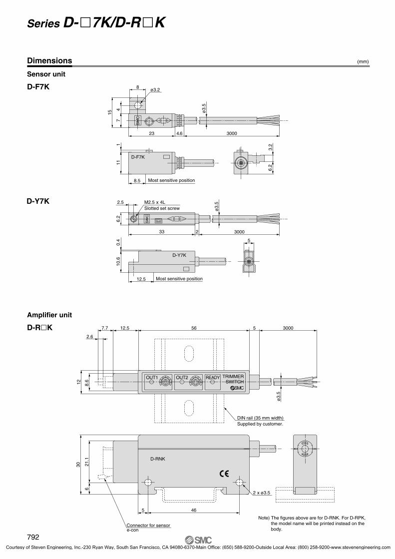
Dimensions
Sensor unit
D-F7K
Amplifier unit
D-RK
D-Y7K
8.612
56
465
512.57.7
2.6
3000
ø3.
5
21.1
6
30
OUT1 OUT2 READY TRIMMERSWITCH
SMC
D-RNK
2 x ø3.5
SM
C
D-F7K
D-Y7K
SM
C
Slotted set screw
111
7
15
4
23
8
3.2
6.2
8.5
4.6 3000
2.5
6.2
33 2
5
10.6
0.4
ø3.
5
ø3.2
ø3.
5
12.5
3000
DIN rail (35 mm width)Supplied by customer.
Connector for sensore-con
(mm)
Note) The figures above are for D-RNK. For D-RPK, the model name will be printed instead on the body.
Most sensitive position
Most sensitive position
M2.5 x 4L
792
Series D-7K/D-RK
P0764-P0810-E.qxd 08.9.29 4:03 PM Page 792
Courtesy of Steven Engineering, Inc.-230 Ryan Way, South San Francisco, CA 94080-6370-Main Office: (650) 588-9200-Outside Local Area: (800) 258-9200-www.stevenengineering.com

Trimmer Auto SwitchSpecific Product Precautions 1Be sure to read before handling.Refer to front matters 38 and 39 for Safety Instructions and pages 362 to 365 for the Auto Switch Common Precautions.
1. Confirm the specifications.Read the specifications carefully and use this product appro-priately. The product may be damaged or malfunction if it is used outside the range of specifications of current load, vol-tage, temperature or impact.
2. Cautions for use in an interlock circuit.When an auto switch is used for an interlock signal requiring high reliability, devise a double interlock system to avoid trouble by providing a mechanical protection function, or by also using an-other switch (sensor) together with the trimmer auto switch. Also perform periodic maintenance and confirm proper operation.
1. Take precautions when multiple cylinders are used close together.When more than 2 trimmer auto switch cylinders are used in close proximity, maintain a minimum actuator interval of 40 mm or more. (When the allowable interval is indicated for each cylinder series, use the specified values.) Magnetic field inter-ference may cause the trimmer auto switches to malfunction.
2. Keep the wiring as short as possible.Use a wire 3 m or shorter between the sensor and amplifier. Although wire length of power supply/output cable should not affect switch function, use a wire 100 m or shorter.
3. Take precautions for the internal voltage drop of the switch.Auto switches may not operate properly depending on the con-nected equipment.
4. Take measures for rotational stoppage of the piston rod.Take measures for rotational stoppage of the piston rod when de-signing by guide, etc. Or use non-rotating type SMC products. The operation may be unstable.
Design and Selection
Warning
Caution
1. Avoid repeatedly bending or stretching lead wires.Broken lead wires will result from applying bending stress or stretching forces to the lead wires.
2. Be sure to connect the connector for sensor to the amplifier before power is applied.
3. Do not allow short circuit of loads.Output is automatically stopped when the protection circuit is working, as the output unit registers any excess current flow, if loads are short circuited. Should this occur, shut off the power supply, remove the cause of this excess current flow and switch on the power again. Take special care to avoid reverse wiring between the power supply line (brown) and the output line (black, white).
4. Avoid incorrect wiring.If the connections are reversed (power supply line + and power supply line –), the trimmer auto switches will be protected by a protection circuit. However, if the power supply line (–) is con-nected to the black, white wire, the trimmer auto switches will be damaged.
Wiring
Caution
1. Never use in an atmosphere with explosive gases.The structure of trimmer auto switches is not designed to pre-vent explosion. Never use in an atmosphere with an explosive gas since this may cause a serious explosion.
1. Do not use in an area where a magnetic field is generated.Trimmer auto switches will malfunction or magnets inside cy-linders will become demagnetized.
2. Do not use in an environment where the trimmer auto switch will be continually ex-posed to water.Although the sensor units of trimmer auto switches satisfy the IEC standard IP67 structure, do not use trimmer auto switches in applications where continually exposed to water splash or spray. Poor insulation or swelling of the potting resin inside trimmer auto switches may cause malfunction.(Amplifier part D-RNK and RPK: IP40)
3. Do not use in an environment with oil or chemicals.Please consult with SMC if trimmer auto switches will be used in an environment with coolant, cleaning solvent, various oils or chemicals. If trimmer auto switches are used under these conditions for even a short time, they may be adversely affec-ted by improper insulation, malfunction due to swelling of the potting resin, or hardening of the lead wires.
4. Take measures against freezing when oper-ating at 5°C or less.
Operating Environment
Warning
Caution
Mounting and Adjustment
Caution1. Do not drop or bump.
Do not drop, bump or apply excessive impacts (980 m/s2 or more for sensor unit and 98 m/s2 or more for amplifier unit) while handling.Although the trimmer auto switch body may not be damaged, the inside of the trimmer auto switch could be damaged and cause a malfunction.
793
D-
4-4-03-AutoSw-UM.qxd 09.11.30 10:00 AM Page 14
Courtesy of Steven Engineering, Inc.-230 Ryan Way, South San Francisco, CA 94080-6370-Main Office: (650) 588-9200-Outside Local Area: (800) 258-9200-www.stevenengineering.com

1. Perform the following maintenance periodically in order to prevent possible danger due to unexpected trimmer auto switch malfunction.1) Secure and tighten trimmer auto switch mounting screws.
If screws become loose or the mounting position is dis-located, retighten them after readjusting the mounting posi-tion.
2) Confirm that there is no damage to lead wires.To prevent faulty insulation, replace trimmer auto switches or repair lead wires, etc., if damage is discovered.
Maintenance
1. Please consult with SMC concerning water resistance, elasticity of lead wires, and usage at welding sites, etc.
Other
Warning
Caution
1. Connection and removal of connector• Hold the lever and connector body with two fingers and in-
sert the connector straight into the pin until it is locked with a click sound.
• To remove the connector, pull it out straight while pressing the lever with one finger.
2. Connection of sensor connector• Cut the sensor lead wire as illustrated to the right.• Referring to the table below, insert each lead wire of the
cable at the position marked with a number corresponding to the color of the lead wire.
• For detailed information about e-con connectors, please con-sult with the manufacturers of the respective connectors.
• Use a sensor conector, ZS-28-CA-3 (1 pc.) or e-con connec-tors as shown below.
Wiring
Caution
20 mm or moreSheath
Insulator
Connector no.1234
Wire core colorBlack (SOUT1)
Blue (GND)White (SOUT2)
Brown (Vsw)
Lever
D-RNK
D-Y7K
• Confirm that the numbers on the connector match the colors of the lead wires and that they are inserted to the bottom. Press part A by hand for temporary fixing.
• Press in the central part of Part A vertically with a tool such as pliers.
• A sensor connector cannot be taken apart for reuse once it is crimped. If the lead wire arrangement is incorrect or if the wire insertion fails, use a new sensor connector.
Part A
ManufacturerSumitomo 3M Limited
Tyco Electronics AMP K.K.OMRON Corporation
Part no.37104-3122-000FL
1473562-4XN2A-1430
Trimmer Auto SwitchSpecific Product Precautions 2Be sure to read before handling.Refer to front matters 38 and 39 for Safety Instructions and pages 362 to 365 for the Auto Switch Common Precautions.
794
P0764-P0810-E.qxd 08.9.29 4:03 PM Page 794
Courtesy of Steven Engineering, Inc.-230 Ryan Way, South San Francisco, CA 94080-6370-Main Office: (650) 588-9200-Outside Local Area: (800) 258-9200-www.stevenengineering.com

Mounting of Amplifier Unit
1. Mounting with screws• Tighten two M3 x 16L mounting screws at a tightening torque
of 0.5 to 0.7 N·m.• Mounting surface should be flat and even. A bumpy or un-
even mounting surface can result in damage to the case.
• Use mounting screws (M3 x 16L) or DIN rail (35 mm width). (DIN rail part no.: ISA-2-1 to 7)
• Adjust offset before mounting of the amplifier unit.
Caution
Washer
M3 x 16L
3. Refer to each applicable actuator’s catalog for the mounting of sensor unit.
• In the case of mounting to the DIN rail, SMC recommends the following end plates: as de-tailed in the table on the right. Consult each manufacturer for the handling and details of end plate.
2. Mounting and removal to DIN railMounting• Hook the claw 1 of the am-
plifier body to the upper part of DIN rail, press down and push horizontally until the claw 2 is locked with a click sound.
Removal• To remove from the DIN rail,
push the amplifier body up-ward and then pull it hori-zontally to release from the claw 1 side.
OU
T1
OU
T2
TR
IMM
ER
SW
ITC
HR
EA
DY
SMC
OU
T1
OU
T2
TR
IMM
ER
SW
ITC
H
RE
AD
Y
SMC
OU
T1
OU
T2
TR
IMM
ER
SW
ITC
HR
EA
DY
SMC
OU
T1
OU
T2
TR
IMM
ER
SW
ITC
H
SMC
ManufacturerOMRON Corporation
IDEC Corporation
Part no.PFP-MBNL6
Claw 2
Claw 1
Trimmer Auto SwitchSpecific Product Precautions 3Be sure to read before handling.Refer to front matters 38 and 39 for Safety Instructions and pages 362 to 365 for the Auto Switch Common Precautions.
795
D-
P0764-P0810-E.qxd 08.9.29 4:03 PM Page 795
Courtesy of Steven Engineering, Inc.-230 Ryan Way, South San Francisco, CA 94080-6370-Main Office: (650) 588-9200-Outside Local Area: (800) 258-9200-www.stevenengineering.com

• Eliminates the harnessing work by cable with connector specifications• Adopts global standardized connector (IEC947-5-2)• IP67 construction
How to Order
Cable length
Solid state auto switchStandard part no.
0.5 m1.0 m3.0 m
SML
Connector model
Applicable Auto Switch
D M9N S A PC
Note) L is available for the D-P4DW type only.
ABD
Note) Type D is available for the D-P4DW type only.
M8—3 pinM8—4 pinM12—4 pin
—
—
—
—
—
—
—
—
—
—
—
—
—
3.0
Lead wire length (m)
1.00.5Applicable modelFunctionMounting
F79, F7P, J79F7NV, F7PV, F7BVF79W, F7PW, J79W
F7NWV, F7BWVF79FF7BA
F7BAVF7NTP4DW
F59, F5P, J59F59W, F5PW, J59W
F59FF5BAF5NT
Electricalentry
Grommet (In-line)Grommet
(Perpendicular)
Grommet (In-line)Grommet
(Perpendicular)
Grommet (In-line)
Grommet(Perpendicular)
Grommet (In-line)
—
2-colorindication
With diagnostic output
Water resistant
With timer
Magnetic field
—
2-color indication
With diagnostic output
Water resistant
With timer
Railmountingstyle
Tie-rodmountingstyle
—
—
—
—
—
—
—
—
—
—
—
—
—
—
—
3.01.00.5
Y59A, Y7P, Y59B
Y69A, Y7PV, Y69B
M9N, M9P, M9B
M9NV, M9PV, M9BV
F8N,F8P,F8B
Y7NW, Y7PW, Y7BW
Y7NWV, Y7PWV, Y7BWV
M9NW, M9PW, M9BW
M9NWV, M9PWV, M9BWV
Y7BA
M9NA, M9PA, M9BA
M9NAV, M9PAV, M9BAV
S791/2, S7P1/2, T791/2
S991/2, S9P1/2, T991/2
S99V1/2, T99V1/2
Grommet (In-line)Grommet
(Perpendicular)
Grommet (In-line)Grommet
(Perpendicular)Grommet
(Perpendicular)
Grommet (In-line)Grommet
(Perpendicular)
Grommet (In-line)Grommet
(Perpendicular)
Grommet (In-line)
Grommet(Perpendicular)
Grommet (In-line)
Grommet(Perpendicular)
—
—
2-colorindication
Water resistant
Connector Specifications
12
1 2
43
Connector model
Pin arrangement
Conformed standard
Impact resistance
Enclosure
Insulation resistance
Withstand voltage
M8–3 pin M8–4 pin M12–4 pin
JIS C 4524, JIS C 4525, IEC 947-5-2, NECA 0402
300 m/s2
IP67 (IEC60529 standard)
100 MΩ or more at 500 M VDC
1500 VAC/1 minute (between contacts), Leak current 1 mA or less
1
3
4
3 4
Made to Order Specifications: Solid State Auto Switch
With Pre-wired Connector1
Refer to SMC website for the details of the products conforming to the international standards.
∗ For the applicable auto switch model, refer to the table below.
Lead wire length (m)Applicable modelFunctionMounting
Electricalentry
Directmountingstyle
Rotaryactuator
796
P0764-P0810-E.qxd 08.9.29 4:03 PM Page 796
Courtesy of Steven Engineering, Inc.-230 Ryan Way, South San Francisco, CA 94080-6370-Main Office: (650) 588-9200-Outside Local Area: (800) 258-9200-www.stevenengineering.com

Connector Pin Arrangement
Dimensions
Sensor type
DC 2-wire type
DC 2-wire, Non-polar type
DC 3-wire type
DC 4-wire type
Brown
—
Brown
Brown
1 pin 2 pin 3 pin 4 pin
Color distinction of lead wire Meaning of contact number
1 pin 2 pin 3 pin 4 pin
Connector model
M8—3 pin 4 pin
M12—4 pin
ø14
44
Sensor section
ø10
31.4
Sensor section
Connector SpecificationsConnector model
Pin arrangement
Conformed standard
Impact resistance
Enclosure
Insulation resistance
Withstand voltage
JIS C 4524, JIS C 4525, IEC 947-5-2, NECA 0402
300 m/s2
IP67 (IEC60529 standard)
100 MΩ or more at 500 M VDC
1500 VAC/1 minute (between contacts), Leak current 1 mA or less
M8–3 pin M8–4 pin M12–4 pin
12
3 4
1 4
3
1 2
43
Connection (Female side) Connector CableMass for Connector TypesAs the parts are not supplied from SMC, refer to the application examples listed in the below.(For detail such as catalog availability, etc., please contact each manufacturer.)
Connector sizePart no. Connector type
M8-3
M8-4
M12-4
4 g
4 g
Approx. 11 g
Mass
M8
M12
SAC-3P
M8-3D
M8-4D
XS3
SAC-4P
VA-4D
XS2
PA5-4I
HR24
CM01-8DP4S
Manufacturer
Phoenix Contact Co., Ltd.
Corrence Corporation
OMROM Corporation
Phoenix Contact Co., Ltd.
Corrence Corporation
OMROM Corporation
Yamatake Corporation
Hirose Electric Co., Ltd.
DKK Ltd.
4
3
Number of pins Applicable series exampleD-APC
D-BPC
D-DPC
M8—4 pin
M12—4 pin
M8—3 pin
—
—
—
Orange
—
Brown
Blue
Blue
Blue
Blue
Black
Black
OUT (+)
—
DC (+)
DC (+)
—
—
—Diagnostic
output
—
OUT (±)
DC (–)
DC (–)
OUT (–)
OUT ( )
OUT
OUT
±
797
With Pre-wired Connector
D-
P0764-P0810-E.qxd 08.9.29 4:03 PM Page 797
Courtesy of Steven Engineering, Inc.-230 Ryan Way, South San Francisco, CA 94080-6370-Main Office: (650) 588-9200-Outside Local Area: (800) 258-9200-www.stevenengineering.com

Made to Order Specifications: Solid State Auto Switch-50: Without Indicator Light (Dark room) Specifications-61: Oilproof, Flexible Cable Specifications
-50Without Indicator Light (for dark room specifications)
Can be used in environments where light should be avoided.
50D
Solid state auto switch model
61D
Dimensions and specifications are common as standard products with the exception of no indicator light.
Lead wire lengthFor lead wire length, refer to page 764.
Lead wire lengthRefer to page 764 for lead wire lengths.
Without indicator light(for dark room specifications)
2
Oilproof, Flexible Heavy-duty Cord Specifications3
Oilproof, flexible heavy-duty cordspecifications
Symbol
Symbol
-61
Applicable part no.: General purpose type, solid state auto switch except D-J51
Note) Please consult with SMC for water resistant type, timer equipped type, diagnostic output type, wide range detection type, magnetic field resistant type, and heat resistant type.
This is the product which uses a heavy-duty cord having flexible characteristics 5 times (SMC comparison) as strong as oilproof heavy-duty cord used in the standard products.
Solid state auto switch part no.Applicable part no: All the solid state auto
switches with the exceptance of D-J51, output diagnostic type, connector type
Note) Oilproof, flexible heavy-duty cord is used for D-Y59 , Y69 , Y7P(V), D-M9, D-M9V, D-M9W, D-M9WV, D-M9AL, D-M9AVL, as standard. No need to suffix -61 to the end of part number.
AB
AB
Specifications are the same as standard products with the exception of lead wire specifications.Lead wire: For D-F8 type············ ø2.7, 0.15 mm2, 3 cores (Brown, Blue, Black), 2 cores (Brown, Blue)For other model nos.··················· ø3.4, 0.15 mm2, 3 cores (Brown, Blue, Black), 2 cores (Brown, Blue)
Dimensions are identical with D-F5 type, J59 type. Lead wire diameter is changed from ø4 to ø3.4. In other series products, it is common as standard product's specifications.
798
P0764-P0810-E.qxd 08.9.29 4:03 PM Page 798
Courtesy of Steven Engineering, Inc.-230 Ryan Way, South San Francisco, CA 94080-6370-Main Office: (650) 588-9200-Outside Local Area: (800) 258-9200-www.stevenengineering.com

( ) values for D-A72
8
15 (
14)
7 (6
)4
23 (22)
Indicator light
D-A80 without indicator light
ø3.2
9 (8.5)
ø3.4
Most sensitive position
6 (6
.2)
3
11.5
(11
.7)
Dimensions
Reed Auto SwitchRail Mounting StyleD-A72/D-A73/D-A80
GrommetElectrical entry: Perpendicular
Mass
Auto switch model
0.5
3
5
10
47
—
10
47
77
10
47
—
D-A72 D-A73 D-A80
(g)
(mm)
Lead wire length(m)
D-A7 (With indicator light)Auto switch model
Applicable load
Load voltage
Load current range (3)
Contact protection circuit
Internal voltage drop
Indicator light
Standard
24 VDC
5 to 40 mA
None
2.4 V or less
Red LED illuminates when turned ON.
CE marking
100 VAC
5 to 20 mA
D-A72
Relay, PLC
200 VAC
5 to 10 mA
D-A73
Relay, PLC
D-A80
Relay, IC circuit, PLC
40 mA
None
1 Ω or less (Including lead wire length of 3 m)
CE marking
D-A8 (Without indicator light)Auto switch model
Applicable load
Load voltage
Maximum load current
Contact protection circuit
Internal resistance
Standard
50 mA 20 mA
Auto Switch Internal Circuit
D-A72
D-A80
D-A73
Note 1) Operating load is an induction load.Note 2) Wiring to the load is 5 m or longer.Note 3) Load voltage is 100 VAC or 200 VAC.Use the contact protection box in any of the above listed situations. The contact point life may decrease. Especially in the case of D-A72, be sure to use the contact protection box. (Refer to page 765 for contact protection box.)
~
~
~
Auto Switch SpecificationsPLC: Programmable Logic Controller
Refer to SMC website for the details of the products conforming to the international standards.
• Lead wires — Oilproof heavy-duty vinyl cord, ø3.4, 0.2 mm2, 2 cores (Brown, Blue), 0.5 m Note 1) Refer to page 764 for reed auto switch common specifications.Note 2) Refer to page 764 for lead wire lengths.Note 3) Under 5 mA, the strength of the indicator light is poor. In some cases, visibility of the
indicator light will not be possible where the output signal is less than 2.5 mA. However, there is no problem in terms of contact output, when an output signal exceeds 1 mA or more.
24 V or lessACDC 48 V AC
DC 100 V ACDC
LED
Ree
d sw
itch
Resistor
Zener diode
Brown
Blue
Ree
d sw
itch
Blue
LED
Ree
d sw
itch
Resistor
Zener diode
Brown
Chokecoil
Contact protection boxCD-P11
Surgeabsorber
OUT Brown
OUT Blue
OUT (+)Brown
OUT (–)Blue
OUT (±)Brown
OUT ( )Blue
±
Contact protection boxCD-P11CD-P12
Contact protection boxCD-P11CD-P12
799
D-
P0764-P0810-E.qxd 08.9.29 4:03 PM Page 799
Courtesy of Steven Engineering, Inc.-230 Ryan Way, South San Francisco, CA 94080-6370-Main Office: (650) 588-9200-Outside Local Area: (800) 258-9200-www.stevenengineering.com

2
ø3.
4
22
8.5
15
74
8
ø3.2
SMC
6.2
3.3
10.2
Auto Switch Internal Circuit
D-A72H
D-A73H
D-A76H
D-A80H
Mass
Dimensions
Auto switch model
0.5
3
5
10
47
—
10
47
—
11
52
—
10
47
77
D-A72H D-A73H D-A76H D-A80H
D-A7H, D-A80H
Auto Switch SpecificationsPLC: Programmable Logic Controller
Refer to SMC website for the details of the products conforming to the international standards.
(g)
(mm)
Reed Auto SwitchRail Mounting StyleD-A7H/D-A80H
GrommetElectrical entry: In-line
Lead wire length(m)
D-A7H (With indicator light)Auto switch model
Applicable load
Load voltage
Max. load voltage/Load current range(3)
Contact protection circuit
Internal voltage drop
Indicator light
Standard
24 VDC
5 to 40 mA
2.4 V or less
100 VAC
5 to 20 mA
D-A72H
Relay, PLC
200 VAC
5 to 10 mA
D-A76H
IC circuit
4 to 8 VDC
20 mA
0.8 V or less
D-A73H
Relay, PLC
None
Red LED illuminates when turned ON.
CE marking
D-A80H
Relay, IC circuit, PLC
40 mA
None
1 Ω or less (Including lead wire length of 3 m)
CE marking
D-A80H (Without indicator light)Auto switch model
Applicable load
Load voltage
Maximum load current
Contact protection circuit
Internal resistance
Standard
50 mA 20 mA
Note 1) Operating load is an induction load.Note 2) In the case the wiring length to load is
more than 5 m.Note 3) Load voltage is 100 VAC or 200 VAC.Use the contact protection box in any of the above listed situations. The contact point life may decrease. Especially in the case of D-A72H, be sure to use the contact protection box. (Refer to page 765 for contact protection box.)
• Lead wires — Oilproof heavy-duty vinyl cord, 0.2 mm2, 2 cores (Brown, Blue), 3 cores (Brown, Black, Blue), 0.5 m
Note 1) Refer to page 764 for reed auto switch common specifications.Note 2) Refer to page 764 for lead wire lengths.Note 3) Under 5 mA, the strength of the indicator light is poor. In some cases, visibility of the
indicator light will not be possible where the output signal is less than 2.5 mA. However, there is no problem in terms of contact output, when an output signal exceeds 1 mA or more.
24 V or lessACDC 48 V AC
DC 100 V ACDC
Blue
LED
Ree
d sw
itch
Resistor
Zener diode
Brown
OUTBlue
OUTBrownChoke
coil
Contact protection boxCD-P11
Surgeabsorber
~
LED
Ree
d sw
itch
Resistor
Zener diode
Brown
Blue
OUT (+)Brown
~
OUT (–)Blue
LED
Ree
d sw
itch
Resistor
Reversecurrentprevention diode
OUTBlack
DC (+) Brown
DC (–)Blue
Load
(+)
(–)
DC power supply
Ree
d sw
itch OUT (±)
Brown
~
OUT ( ) Blue
±
Contact protection boxCD-P11CD-P12
Contact protection boxCD-P11CD-P12
Indicator lightD-A80H without indicator light
Most sensitive position
800
P0764-P0810-E.qxd 08.9.29 4:03 PM Page 800
Courtesy of Steven Engineering, Inc.-230 Ryan Way, South San Francisco, CA 94080-6370-Main Office: (650) 588-9200-Outside Local Area: (800) 258-9200-www.stevenengineering.com

Auto Switch Internal Circuit
D-A73C
D-A80C
Dimensions
Reed Auto SwitchRail Mounting StyleD-A73C/D-A80C
Mass (g)
(mm)
1. Confirm that the connector is appropriately tightened. If tightened insufficiently, the waterproof performance will deteriorate.
2. Refer to Best Pneumatics No. 2 for the details.
PrecautionsCaution
Auto switch model
0.5
3
5
12
54
84
12
54
84
D-A73C D-A80C
Lead wire length(m)
D-A73C (With indicator light)D-A73C
Relay, PLC
24 VDC
5 to 40 mA
None
2.4 V or less
Red LED illuminates when turned ON.
CE marking
D-A80C
Relay, IC circuit, PLC
50 mA
None
1 Ω or less (Including lead wire length of 3 m)
CE marking
D-A80C (Without indicator light)
Connector
Note 1) Operating load is an induction load.Note 2) Wiring to the load is 5 m or longer.Use the contact protection box in any of the above listed situations. The contact point life may decrease. (Refer to page 765 for contact protection box.)
Auto Switch SpecificationsPLC: Programmable Logic Controller
Refer to SMC website for the details of the products conforming to the international standards.
Indicator lightD-A80C without indicator light
Most sensitive position
Lead wire with connector
Auto switch model
Applicable load
Load voltage
Load current range (4)
Contact protection circuit
Internal voltage drop
Indicator light
Standard
Auto switch model
Applicable load
Load voltage
Maximum load current
Contact protection circuit
Internal resistance
Standard
24 V ACDC
• Lead wires — Oilproof heavy-duty vinyl cord, ø3.4, 0.2 mm2, 2 cores (Brown, Blue), 0.5 mNote 1) Refer to page 764 for reed auto switch common specifications.Note 2) Refer to page 764 for lead wire lengths.Note 3) Lead wire with connector may be shipped with the auto switch.Note 4) Under 5 mA, the strength of the indicator light is poor. In some cases, visibility of the
indicator light will not be possible where the output signal is less than 2.5 mA. However, there is no problem in terms of contact output, when an output signal exceeds 1 mA or more.
Blue
LED
Ree
d sw
itch
Resistor
Zener diode
Brown
OUT (–)Blue
OUT (+)Brown
Choke coil
Contact protection boxCD-P12
Zener diode
Ree
d sw
itch Contact
protection boxCD-P11CD-P12
OUT (±)Brown
~
OUT ( ) Blue
±
801
D-
P0764-P0810-E.qxd 08.9.29 4:03 PM Page 801
Courtesy of Steven Engineering, Inc.-230 Ryan Way, South San Francisco, CA 94080-6370-Main Office: (650) 588-9200-Outside Local Area: (800) 258-9200-www.stevenengineering.com
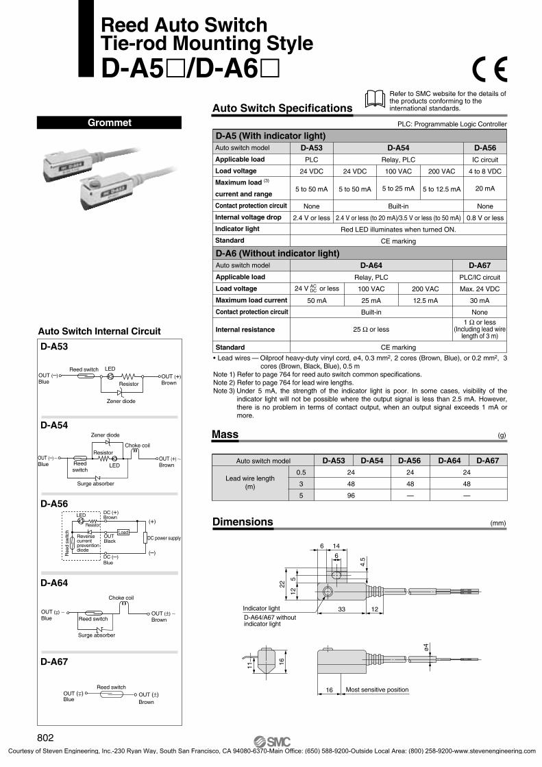
1233
22
512
4.5
6 14
6
D-A64/A67 without indicator light
Indicator light
ø4
16 Most sensitive position
1611
Auto Switch Internal Circuit
D-A53
D-A64
D-A56
Mass
Dimensions
(g)
(mm)
Grommet
D-A67
D-A54
Auto switch model
0.5
3
5
24
48
96
24
48
—
24
48
—
D-A53 D-A54 D-A56 D-A64 D-A67
Lead wire length(m)
D-A5 (With indicator light)Auto switch model
Applicable load
Load voltage
Maximum load (3)
current and range
Contact protection circuit
Internal voltage drop
Indicator light
Standard
D-A53
PLC
24 VDC
5 to 50 mA
None
2.4 V or less
24 VDC
5 to 50 mA
D-A54
Relay, PLC
100 VAC
5 to 25 mA
Built-in
2.4 V or less (to 20 mA)/3.5 V or less (to 50 mA)
200 VAC
5 to 12.5 mA
D-A56
IC circuit
4 to 8 VDC
20 mA
None
0.8 V or less
D-A6 (Without indicator light)Auto switch model
Applicable load
Load voltage
Maximum load current
Contact protection circuit
Internal resistance
200 VAC
12.5 mA
D-A67
PLC/IC circuit
Max. 24 VDC
30 mA
None
1 Ω or less(Including lead wire
length of 3 m)
D-A64
Relay, PLC
100 VAC
25 mA
Built-in
25 Ω or less
Red LED illuminates when turned ON.
CE marking
50 mA
Standard CE marking
PLC: Programmable Logic Controller
Refer to SMC website for the details of the products conforming to the international standards.Auto Switch Specifications
Reed Auto SwitchTie-rod Mounting StyleD-A5/D-A6
Zener diode
Reed switch LED
Resistor
OUT (–)Blue
OUT (+)Brown
Zener diode
LED
ResistorChoke coil
Surge absorber
OUT (–)Blue
OUT (+) BrownReed
switch
LED
Ree
d sw
itch
Resistor
OUTBlack
DC (+) Brown
DC (–)Blue
Load
(+)
(–)
DC power supplyReverse current prevention diode
Reed switch
Choke coil
Surge absorber
OUT ( ) Blue
OUT (±) Brown
±
Reed switchOUT (±)Brown
OUT ( ) Blue
±
24 V or lessACDC
• Lead wires — Oilproof heavy-duty vinyl cord, ø4, 0.3 mm2, 2 cores (Brown, Blue), or 0.2 mm2, 3 cores (Brown, Black, Blue), 0.5 m
Note 1) Refer to page 764 for reed auto switch common specifications.Note 2) Refer to page 764 for lead wire lengths.Note 3) Under 5 mA, the strength of the indicator light is poor. In some cases, visibility of the
indicator light will not be possible where the output signal is less than 2.5 mA. However, there is no problem in terms of contact output, when an output signal exceeds 1 mA or more.
802
P0764-P0810-E.qxd 08.9.29 4:03 PM Page 802
Courtesy of Steven Engineering, Inc.-230 Ryan Way, South San Francisco, CA 94080-6370-Main Office: (650) 588-9200-Outside Local Area: (800) 258-9200-www.stevenengineering.com
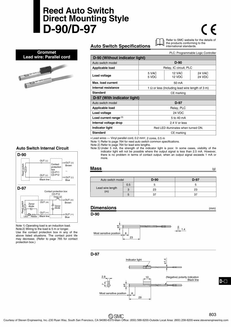
1.4
8
23
ø4
Most sensitive position
8
29
10
ø4
(Negative) polarity indicationBlack line
Most sensitive position
ø1.
4Indicator light
7
2.8
Auto Switch Internal Circuit
D-90
Mass
Dimensions
(g)
(mm)
Reed Auto SwitchDirect Mounting StyleD-90/D-97
GrommetLead wire: Parallel cord
D-97
Auto switch model
0.5
3
5
5
23
37
5
23
37
D-90 D-97
Lead wire length(m)
Note 1) Operating load is an induction load.Note 2) Wiring to the load is 5 m or longer.Use the contact protection box in any of the above listed situations. The contact point life may decrease. (Refer to page 765 for contact protection box.)
D-90 (Without indicator light)Auto switch model
Applicable load
Load voltage
Max. load current
Internal resistance
Standard
D-97 (With indicator light) Auto switch model
Applicable load
Load voltage
Load current range (3)
Internal voltage drop
Indicator light
Standard
D-97Relay, PLC
24 VDC
5 to 40 mA
2.4 V or less
Red LED illuminates when turned ON.
CE marking
D-90Relay, IC circuit, PLC
50 mA
1 Ω or less (Including lead wire length of 3 m)
CE marking
5 VAC5 VDC
24 VAC24 VDC
D-90
D-97
PLC: Programmable Logic Controller
Refer to SMC website for the details of the products conforming to the international standards.Auto Switch Specifications
12 VAC12 VDC
• Lead wires — Vinyl parallel cord, 0.2 mm2, 2 cores, 0.5 m Note 1) Refer to page 764 for reed auto switch common specifications.Note 2) Refer to page 764 for lead wire lengths.Note 3) Under 5 mA, the strength of the indicator light is poor. In some cases, visibility of the
indicator light will not be possible where the output signal is less than 2.5 mA. However, there is no problem in terms of contact output, when an output signal exceeds 1 mA or more.
Ree
d sw
itch OUT (±)
Brown
OUT ( ) Blue
±OUT ( ) ±
OUT (±)
Black line
Contact protection boxCD-P11CD-P12
LED
Ree
d sw
itch
Resistor
Zener diode
Choke coil
Contact protection boxCD-P12
Black line
OUT (+)Brown
OUT (–)Blue
OUT (+)
OUT (–)
Zener diode
803
D-
P0764-P0810-E.qxd 08.9.29 4:03 PM Page 803
Courtesy of Steven Engineering, Inc.-230 Ryan Way, South San Francisco, CA 94080-6370-Main Office: (650) 588-9200-Outside Local Area: (800) 258-9200-www.stevenengineering.com
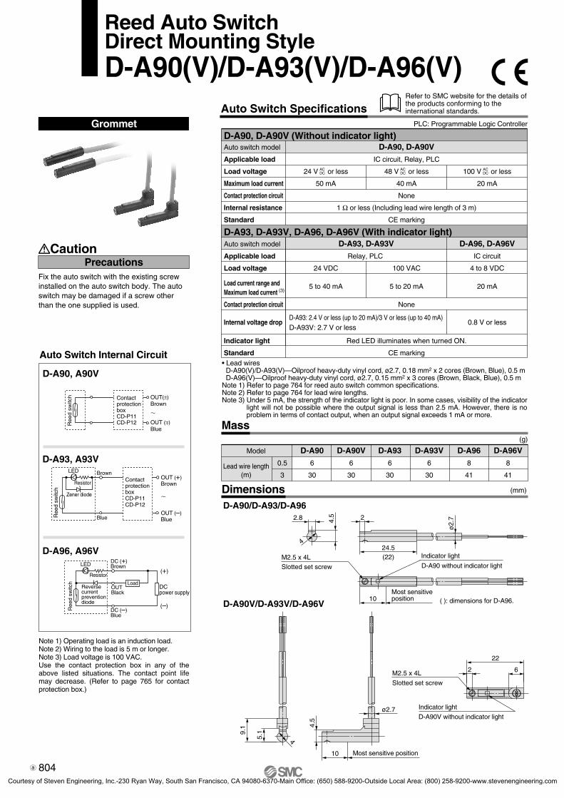
ø2.
72
24.5(22)
2.8 4.5
4
10 ( ): dimensions for D-A96.
D-A90 without indicator light
Indicator light
Most sensitive position
Slotted set screwM2.5 x 4L
4
9.1
5.1
ø2.7
10
4.5
Most sensitive position
2
22
6
D-A90V without indicator light
Indicator light
Slotted set screw
M2.5 x 4L
GrommetAuto Switch Specifications
D-A90, D-A90V (Without indicator light)Auto switch model
Applicable load
Load voltage
Maximum load current
Contact protection circuit
Internal resistance
Standard
D-A93, D-A93V, D-A96, D-A96V (With indicator light)Auto switch model
Applicable load
Load voltage
Load current range andMaximum load current (3)
Contact protection circuit
Internal voltage drop
Indicator light
Standard
D-A90, D-A90V
IC circuit, Relay, PLC
24 V or less
50 mA
None
1 Ω or less (Including lead wire length of 3 m)
CE marking
48 V or less
40 mA
100 V or less
20 mA
D-A93, D-A93V
Relay, PLC
24 VDC
5 to 40 mA
None
D-A93: 2.4 V or less (up to 20 mA)/3 V or less (up to 40 mA)D-A93V: 2.7 V or less
Red LED illuminates when turned ON.
CE marking
100 VAC
5 to 20 mA
D-A96, D-A96V
IC circuit
4 to 8 VDC
20 mA
0.8 V or less
Note 1) Operating load is an induction load.Note 2) Wiring to the load is 5 m or longer.Note 3) Load voltage is 100 VAC.Use the contact protection box in any of the above listed situations. The contact point life may decrease. (Refer to page 765 for contact protection box.)
Fix the auto switch with the existing screw installed on the auto switch body. The auto switch may be damaged if a screw other than the one supplied is used.
PrecautionsCaution
Model
0.5
3Lead wire length
(m)
D-A90
6
30
D-A90V
6
30
D-A93
6
30
D-A93V
6
30
D-A96
8
41
D-A96V
8
41
(g)
Mass
Auto Switch Internal Circuit
D-A90, A90V
D-A93, A93V
D-A96, A96V
DimensionsD-A90/D-A93/D-A96
D-A90V/D-A93V/D-A96V
(mm)
PLC: Programmable Logic Controller
Refer to SMC website for the details of the products conforming to the international standards.
Reed Auto SwitchDirect Mounting StyleD-A90(V)/D-A93(V)/D-A96(V)
• Lead wires D-A90(V)/D-A93(V)—Oilproof heavy-duty vinyl cord, ø2.7, 0.18 mm2 x 2 cores (Brown, Blue), 0.5 mD-A96(V)—Oilproof heavy-duty vinyl cord, ø2.7, 0.15 mm2 x 3 cores (Brown, Black, Blue), 0.5 m
Note 1) Refer to page 764 for reed auto switch common specifications.Note 2) Refer to page 764 for lead wire lengths.Note 3) Under 5 mA, the strength of the indicator light is poor. In some cases, visibility of the indicator
light will not be possible where the output signal is less than 2.5 mA. However, there is no problem in terms of contact output, when an output signal exceeds 1 mA or more.
ACDC
ACDC
ACDC
Reed s
witc
h OUT(±)Brown
OUT ( ) Blue
±
Contact protection boxCD-P11CD-P12
Blue
LED
Ree
d sw
itch
Resistor
Zener diode
BrownOUT (+)Brown
OUT (–)Blue
Contact protection boxCD-P11CD-P12
LED
Ree
d sw
itch
Resistor
Reverse current prevention diode
OUTBlack
DC (+) Brown
DC (–)Blue
Load
(+)
(–)
DC power supply
804
4-4-03-AutoUM.qxd 09.9.30 5:16 PM Page 5
Courtesy of Steven Engineering, Inc.-230 Ryan Way, South San Francisco, CA 94080-6370-Main Office: (650) 588-9200-Outside Local Area: (800) 258-9200-www.stevenengineering.com

7
2.8
ø3.
4
8
23
ø4
Most sensitive position
Indicator light
ø3.
4
8
29
10
ø4
Most sensitive position
Auto Switch Internal Circuit
D-90A
Mass
Dimensions
(g)
(mm)
Reed Auto SwitchDirect Mounting StyleD-90A/D-93A
GrommetLead wire: Heavy-duty cord
D-93A
Auto switch model
0.5
3
5
9
47
77
9
47
77
D-90A D-93A
Lead wire length(m)
D-90A
D-93A
D-90A (Without indicator light)Auto switch model
Applicable load
Load voltage
Max. load current
Internal resistance
Standard
D-93A (With indicator light)Auto switch model
Applicable load
Load voltage
Load current range (3)
Internal voltage drop
Indicator light
Standard
D-93ARelay, PLC
2.4 V or less
Red LED illuminates when turned ON.
CE marking
D-90ARelay, IC circuit, PLC
1 Ω or less (Including lead wire length of 3 m)
CE marking
5 VAC5 VDC
100 VAC100 VDC
20 mA
24 VAC24 VDC
12 VAC12 VDC
50 mA
24 VDC
5 to 40 mA
100 VAC
5 to 20 mA
Note 1) Operating load is an induction load.Note 2) Wiring to the load is 5 m or longer.Note 3) Load voltage is 100 VAC.Use the contact protection box in any of the above listed situations. The contact point life may decrease. (Refer to page 765 for contact protection box.)
PLC: Programmable Logic Controller
Refer to SMC website for the details of the products conforming to the international standards.Auto Switch Specifications
• Lead wires — Oilproof heavy-duty vinyl cord, 0.2 mm2, 2 cores (Brown, Blue), 0.5 mNote 1) Refer to page 764 for reed auto switch common specifications.Note 2) Refer to page 764 for lead wire lengths.Note 3) Under 5 mA, the strength of the indicator light is poor. In some cases, visibility of the
indicator light will not be possible where the output signal is less than 2.5 mA. However, there is no problem in terms of contact output, when an output signal exceeds 1 mA or more.
Ree
d sw
itch Contact
protection boxCD-P11CD-P12
LED
Ree
d sw
itch
Resistor
Zener diode
Brown
Blue
OUT (+)Brown
OUT (–)Blue
Contact protection boxCD-P11CD-P12
±
OUT(±)Brown
OUT( ) Blue
805
D-
P0764-P0810-E.qxd 08.9.29 4:03 PM Page 805
Courtesy of Steven Engineering, Inc.-230 Ryan Way, South San Francisco, CA 94080-6370-Main Office: (650) 588-9200-Outside Local Area: (800) 258-9200-www.stevenengineering.com

ø3.
4
1.5
8
25.5
Arm
D-R731
8.5
Most sensitive position
D-R732
8.5
Most sensitive position
D-R802
8.5
Most sensitive position
ø3.
4
8
1.525.5
Arm
D-R801
8.5
Most sensitive position
ø3.
4
8
1.525.5
Arm
32.5°
8
1
11.5
7.2
1.5
ø3.
4
8
25.5
Arm
11.5
32.5
°
8
1
7.2
1
8
11.5
7.2
32.5°
7.2
18
11.5
32.5
°
GrommetElectrical entry: In-line
Mass
Auto Switch Internal Circuit
D-R731, R732
D-R801, R802
Left-hand mounting Right-hand mounting
D-R1D-R2
D-R731, D-R732Relay, PLC
(g)
Dimensions
Auto switch modelApplicable loadLoad voltageLoad current rangeInternal voltage dropIndicator lightStandard
D-R73 (With indicator light)
2.4 V or lessRed LED illuminates when turned ON.
CE marking
100 VAC5 to 20 mA
24 VDC5 to 40 mA
40 mA 20 mA
D-R731: Right-hand mounting D-R732: Left-hand mounting
D-R801: Right-hand mounting D-R802: Left-hand mountingNote 1) Operating load is an induction load.Note 2) Wiring to the load is 5 m or longer.Note 3) Load voltage is 100 VAC.Use the contact protection box in any of the above listed situations. The contact point life may decrease. (Refer to page 765 for contact protection box.)
D-R73 D-R800.5
3
11
49
11
49Lead wire length
(m)
Auto switch model
(mm)
D-R801, D-R802Relay, IC circuit, PLC
Auto switch modelApplicable loadLoad voltageMax. load currentInternal resistanceStandard
D-R80 (Without indicator light)
1 Ω or less (Including lead wire length of 3 m)CE marking
50 mA
PLC: Programmable Logic Controller
Refer to SMC website for the details of the products conforming to the international standards.Auto Switch Specifications
Reed Auto SwitchDirect Mounting StyleD-R73/D-R80
ACDC100 V24 V or lessAC
DCACDC48 V
• Lead wires — Oilproof heavy-duty vinyl cord, ø.3.4, 0.2 mm2, 2 cores (Brown, Blue), 0.5 mNote 1) Refer to page 764 for reed auto switch common specifications.Note 2) Refer to page 764 for lead wire lengths.Note 3) Under 5 mA, the strength of the indicator light is poor. In some cases, visibility of
the indicator light will not be possible where the output signal is less than 2.5 mA. However, there is no problem in terms of contact output, when an output signal exceeds 1 mA or more.
LED
Resistor
Zenerdiode
Brown
Blue
OUT (+)Brown
OUT (–)Blue
Ree
d sw
itch
Contact protection boxCD-P11CD-P12
OUT (±)Brown
OUT (±)Blue
Ree
d sw
itch Contact
protection boxCD-P11CD-P12
806
P0764-P0810-E.qxd 08.9.29 4:03 PM Page 806
Courtesy of Steven Engineering, Inc.-230 Ryan Way, South San Francisco, CA 94080-6370-Main Office: (650) 588-9200-Outside Local Area: (800) 258-9200-www.stevenengineering.com

ConnectorElectrical entry: In-line
D-R731C: Right-hand mounting D-R732C: Left-hand mounting
D-R801C: Right-hand mounting D-R802C: Left-hand mounting
Auto Switch Internal Circuit
D-R731C, R732C
D-R801C, R802C
Left-hand mounting Right-hand mounting
D-R1CD-R2C
CautionPrecautions
Mass
Note 1) Operating load is an induction load.Note 2) Wiring to the load is 5 m or longer.Use the contact protection box in any of the above listed situations. The contact point life may decrease. (Refer to page 765 for contact protection box.)
D-R73C D-R80C0.5
3
5
12
51
81
12
51
81
Lead wire length(m)
Auto switch model
Reed Auto SwitchDirect Mounting StyleD-R73C/D-R80C
(g)
Dimensions (mm)
D-R731C, D-R732CRelay, PLC
Auto switch modelApplicable loadLoad voltageLoad current rangeInternal voltage dropIndicator lightStandard
D-R73C (With indicator light)
2.4 V or lessRed LED illuminates when turned ON.
CE marking
24 VDC5 to 40 mA
24 V ACDC
• Lead wires — Oilproof heavy-duty vinyl cord, ø.3.4, 0.2 mm2, 2 cores (Brown, Blue), 0.5 mNote 1) Refer to page 764 for reed auto switch common specifications.Note 2) Refer to page 764 for lead wire lengths.Note 3) Under 5 mA, the strength of the indicator light is poor. In some cases, visibility of the
indicator light will not be possible where the output signal is less than 2.5 mA. However, there is no problem in terms of contact output, when an output signal exceeds 1 mA or more.
D-R801C, D-R802CRelay, IC circuit, PLC
Auto switch modelApplicable loadLoad voltageMax. load currentInternal resistanceStandard
D-R80C (Without indicator light)
1 Ω or less (Including lead wire length of 3 m)CE marking
50 mA
PLC: Programmable Logic Controller
Refer to SMC website for the details of the products conforming to the international standards.Auto Switch Specifications
Confirm that there is no looseness after wiring. The looseness will decrease water resistance.
Most sensitive position
Most sensitive position
Most sensitive position
Most sensitive position
LED
Resistor
Zenerdiode
Brown
Blue
Ree
d sw
itch
Choke coil
Contact protection boxCD-P12
OUT (+)Brown
OUT (–)Blue
Zener diode
Contact protectionboxCD-P11CD-P12
OUT (±)Brown
~
OUT (±)Blue
Ree
d sw
itch
807
D-
P0764-P0810-E.qxd 08.9.29 4:03 PM Page 807
Courtesy of Steven Engineering, Inc.-230 Ryan Way, South San Francisco, CA 94080-6370-Main Office: (650) 588-9200-Outside Local Area: (800) 258-9200-www.stevenengineering.com

1.8
36.
2
14
ø3.4
11.5 Most sensitive position
15
74
8
23.5
Indicator light
ø3.2
Auto Switch Internal Circuit
D-A79W Mass
Dimensions
(g)
(mm)
Grommet
Indicator light/Display method
Auto switch model
0.5
3
11
53
D-A79W
Lead wire length(m)
Note 1) Operating load is an induction load.Note 2) Wiring to the load is 5 m or longer.Use the contact protection box in any of the above listed situations. The contact point life may decrease. (Refer to page 765 for contact protection box.)
D-A79W (With indicator light)Auto switch model
Applicable load
Load voltage
Load current range (3)
Contact protection circuit
Internal voltage drop
Indicator light
D-A79W
Relay, PLC
24 VDC
5 to 40 mA
None
4 V or less
Standard CE marking
PLC: Programmable Logic Controller
Refer to SMC website for the details of the products conforming to the international standards.Auto Switch Specifications
2-Color Indication Reed Auto SwitchRail Mounting StyleD-A79W
The proper operating range can be determined by the color of the light.(Red → Green ← Red)
Reed switch
LED
OUT (+)Brown
OUT (–)Blue
Mai
n ci
rcui
tof
sw
itch
Reverse flow prevent diode
Operating range
IndicationGreenRed Red
• Lead wires — Oilproof heavy-duty vinyl cord, ø3.4, 0.2 mm2, 2 cores (Brown, Blue), 0.5 mNote 1) Refer to page 764 for reed auto switch common specifications.Note 2) Refer to page 764 for lead wire lengths.Note 3) Under 5 mA, the strength of the indicator light is poor. In some cases, visibility of the
indicator light will not be possible where the output signal is less than 2.5 mA. However, there is no problem in terms of contact output, when an output signal exceeds 1 mA or more.
Proper operating range
Operating range .......... Red LED illuminates.Proper operating range .......... Green LED illuminates.
808
4-4-03-AutoSw-UM.qxd 09.11.30 10:00 AM Page 15
Courtesy of Steven Engineering, Inc.-230 Ryan Way, South San Francisco, CA 94080-6370-Main Office: (650) 588-9200-Outside Local Area: (800) 258-9200-www.stevenengineering.com

11
160.
5
Most sensitive position12
ø4
1233
23
134.
9
146
7
Indicator light
ø4.5
Auto Switch Internal Circuit
D-A59W Mass
Dimensions
(g)
(mm)
Grommet
Indicator light/Display method
Auto switch model
0.5
3
25
80
D-A59W
Lead wire length(m)
D-A59W (With indicator light)Auto switch model
Applicable load
Load voltage
Load current range(3)
Contact protection circuit
Internal voltage drop
Indicator light
Standard
D-A59W
Relay, PLC
24 VDC
5 to 40 mA
Built-in
4 V or less
CE marking
PLC: Programmable Logic Controller
Refer to SMC website for the details of the products conforming to the international standards.Auto Switch Specifications
2-Color Indication Reed Auto SwitchTie-rod Mounting StyleD-A59W
Choke coil
Zener diodeReed switch
LED
OUT (+)Brown
OUT (–)Blue
Mai
n ci
rcui
tof
sw
itch
Operating range
IndicationGreen Red
• Lead wires — Oilproof heavy-duty vinyl cord, ø4, 0.3 mm2, 2 cores (Brown, Blue), 0.5 mNote 1) Refer to page 764 for reed auto switch common specifications.Note 2) Refer to page 764 for lead wire lengths.Note 3) Under 5 mA, the strength of the indicator light is poor. In some cases, visibility of the
indicator light will not be possible where the output signal is less than 2.5 mA. However, there is no problem in terms of contact output, when an output signal exceeds 1 mA or more.
The proper operating range can be determined by the color of the light.(Red → Green ← Red)
Proper operating range
Operating range .......... Red LED illuminates.Proper operating range .......... Green LED illuminates.
809
D-
4-4-03-AutoSw-UM.qxd 09.11.30 10:00 AM Page 16
Courtesy of Steven Engineering, Inc.-230 Ryan Way, South San Francisco, CA 94080-6370-Main Office: (650) 588-9200-Outside Local Area: (800) 258-9200-www.stevenengineering.com