rotary actuator newthe rotary actuator body can be mounted directly. not possible for size 10 to 40...
TRANSCRIPT

+
Rotating angle: 90 , 180 , 270All series can rotate up to 270 .The use of specially designed seals and stoppers now enables our compact vane type rotary actuators to rotate up to 270 . (Single vane type)
0 to 230 (Size 10, 40)
0 to 240 (Size 15 to 30)
0 to 175
0 to 85
Rotating angle Rotating angle adjustment range
With auto switch unit
With angle adjuster unitWith angle adjuster unit
With auto switch unit
Two shaft options available
Port locations modified
Single shaft Double shaft
Many combinations available!
25 25
NewNew
Side ported (Size 10, 15)
Conventional typeParallel pipingNewNew
NewNew
The port size is unified to M3.
Double shaft (W shaft)
270
180
90
Change in angle: Parallel piping (0 ), Conventional type (25 )
Rotary ActuatorVane Type 10, 15, 20, 30, 40
CAT.ES20-230A
Series CRB2
NewNewRoHS

Connecting port location: Side ported or Axial portedThe port location can be selectedaccording to the application. (Size 10 to 40 with unit(s) are side ported only.)
Direct mountingThe rotary actuator body can be mounted directly.
Not possible for size 10 to 40 with unit(s).
Double vane type is standardized for 90 and 100 .The outside dimensions of the double vane type are equivalent to those of the single vane type (except size 10). Double vane construction can get twice the torque of the single vane type.
CRB2
The mounting position of the auto switch can be set freely.The switch can be fixed in the desired position in the circumferential direction.
Series CRB2
Side ported Axial ported
Size10 15 20 4030
90
100
180
270
90
100
180
270
Series Vane type
Single
Double
Rotating angle
Basic typeCRB2
With angle adjusterCRB2BWU
Screw x 3
Features 1

Vane Type
Series Single vane (S) Double vane (D)
CRB2
1. It consists of a shaft that is integrated with the vane that slides along the inner surface of the body, and a stopper.
2. The air that is supplied from port A pushes the vane, thus creating torque in the shaft.
3. The air in the exhaust chamber discharges via port B and rotates clockwise.
4. The vane stops as it comes in contact with the stopper.5. Similarly, when air is supplied from port B, it rotates
counterclockwise.
1. It consists of a shaft that is integrated with the 2 vanes that slide along the inner surface and 2 stoppers.
2. The air that is supplied from port A passes through the passage in the shaft in order to also supply air to the other chamber. Thus, the air pushes 2 vanes and creates torque in the shaft.
3. Its movement consists of the same rotation as that of the single vane.
How to Mount Loads
How to connect a load directly to a single flat shaft
To secure the load, select a screwof an appropriate size from those listed in tables (1) and (2) by taking the shaft's single flat bearing stress strength into consideration.
The plate thickness (t) in the table above indicates a reference value when a carbon steel is used. Besides, we do not manufacture a holding block.
Fig. 1 Fig. 2
Screw for holding a load
Holding block
CRB2
Size10152030
Shaft bore size4568
ScrewM4 or larger
M5 or larger
M6 or larger
Table (1) Using Screw Directly (Fig. 1)
CRB2
Size10152030
Shaft bore size4568
Screw
M3 or larger
M4 or largerM5 or larger
Plate thickness (t)2 or wider2.3 or wider3.6 or wider4 or wider
Table (2) Using Holding Block (Fig. 2)Series Series
Working Principle/How to Mount Loads Series CRB2
StopperStopper
Single flat
Hexagon sockethead cap screw
Shaft
VaneVane
Body
Shaft
Body
Front matter 1

Selection Procedures Note Selection Example
Operating conditions
Calculate the inertial moment of load.
Calculate the required torque for each load type and confirm that the values fall in the effective torque range.
• Static load (Ts)Required torque: T = Ts
• Resistance load (Tf)Required torque: T = Tf x (3 to 5)
• Inertial load (Ta)Required torque: T = Ta x 10
Confirm that the time falls in the rotation time adjustment range.
Calculate the kinetic energy of the load and confirm that the energy is within the allowable range.
Confirm that the load applied to the product is within the allowable range.
Air consumption and required air flow capacity are calculated when necessary.
Refer to the Model Selection Software (Pneumatic Model Selection Program Ver.4.0) on the SMC website (http://www.smcworld.com) for details.
Operating conditions are as follows:• Tentative model• Operating pressure (MPa)• Mounting orientation • Load type
Static loadResistance loadInertial load
• Load dimensions (m)• Load mass (kg)• Rotation time (s) • Rotating angle (rad)
• When the resistance load is rotated, the required torque calculated from the inertial load must be added.
Required torqueT = Tf x (3 to 5) + Ta x 10
• Consider the time after converted in the time per 90 .(0.6 s/180 is converted to 0.3 s/90 .)
• If the energy exceeds the allowable range, a suitable cushioning mechanism such as a shock absorber must be externally installed.
• If the load exceeds the allowable range, a bearing or similar must be externally installed.
• Loads are generated from multiple parts. The inertial moment of each load is calculated, and then totaled.
• The unit for the rotating angle is radian. 180 = rad
90 = /2rad
Tentative model: CRB2BS30-180SZOperating pressure: 0.4 MPaMounting orientation: Vertical Load type: Inertial loadRotation time: 0.6 s Rotating angle: rad (180 )
Thrust load: M0.15 x 9.8 + 0.1 x 9.8 = 2.45 [N] 2.45 [N] Allowable thrust load OK
Calculation of Moment of Inertia
Calculation of Required Torque
Confirmation of Rotation Time
Calculation of Kinetic Energy
Confirmation of Allowable Load
Calculation of Air Consumption and Required Air Flow Capacity
Model Selection
2t2
Inertial load: TaTa = · ·
· = [rad/s2]
T = Ta x 10
0.055 Nm Effective torque OK
= 0.000315 x x 10 = 0.055 [N·m]
Required torque: T
2 x 0.62
0.04 t 0.3t = 0.3 s/90 OK
Kinetic energy: E12
E = · · 2
12
E = x 0.000315 x ( ) = 0.01725 [J]
=
0.01725 [J] Allowable energy OK
2·t
2 x 0.6
2
1 = 0.15 x + 0.15 x 0.0252 = 0.000150.062 + 0.032
12
Inertial moment of load 1: 1
2 = 0.1 x + 0.1 x 0.042 = 0.0001650.012
2
Inertial moment of load 2: 2
= 1 + 2 = 0.000315 [kg·m2]Total inertial moment:
1
2
3
4
5
6
25
40
60
30 0.15 kg
r = 10, 0.1 kgLoad 2
Load 1
Front matter 2

12
r
123r2 + a2
= m·
a
K: Moment of inertia around the load center of gravity
= K + m·L2
K = m· r2
2
r
1. Find the moment of inertia B around the
rotation of shaft (B).2. B is converted to the
moment of inertia A around the rotation of shaft (A).
A = ( )2· B
ab
r2
2= m·
12a2 + b2
= m·
a2= m·
r
r
(A)(B)
Number of teeth = b
Number of teeth = a
L
ba
ba
a
r2
4= m·
4. Round plate
r
1. Thin shaft 6. Thin round plate
2. Thin rectangular plate
3. Thin rectangular plate (Including rectangular parallelepiped)
4. Round plate (Including column)
7. Cylinder
8. When the rotational axis and load center of gravity are not consistent
9. Gear transmission
5. Solid spherePosition of rotational axis: Through the center of diameter
Position of rotational axis: Through the center axis
Position of rotational axis: Perpendicular to the plate through the center of gravity
Position of rotational axis: Parallel to side b and throughthe center of gravity
Position of rotational axis: Perpendicular to the shaftthrough the center of gravity
Position of rotational axis: Through the center of diameterand gravity.
Position of rotational axis: Through the center of diameter
: Moment of inertia m: Load massEquation Table of Moment of Inertia1-1
Calculation of Moment of Inertia1
Series CRB2
12a2
= m·
2r2
5= m·
Front matter 3

If the shaft is located at a desired point of the load:1
If the load is divided into multiple loads:2
Calculation Example
a = 0.2 m, b = 0.1 m, L = 0.05 m, m = 1.5 kg
1 = 1.5 x = 6.25 x 10⁻³ kg·m2
2 = 1.5 x 0.052 = 3.75 x 10⁻³ kg·m2
= (6.25 + 3.75) x 10-3 = 0.01 kg·m2
120.22 + 0.12
Example) 1. If the load is the thin rectangular plate: Obtain the center of gravity of load as 1, a provisional shaft.
2. Obtain the actual moment of inertia 2 around the shaft, with the premise that the mass of the load itself is concentrated in the load’s center of gravity point.
3. Obtain the actual moment of inertia .
1 = m·
2 = m·L2
= 1 + 2
12a2 + b2
m1 = 2.5 kg, m2 = 0.5 kg, r1 = 0.1 m, r2 = 0.02 m, L = 0.08 m
Example) 1. If the load is divided into the 2 cylinders:The center of gravity of load 1 matches the shaft.The center of gravity of load 2 differs from the shaft.
Obtain the moment of inertia of load 1:
2. Obtain the moment of inertia of load 2.
3. Obtain the actual moment of inertia .
m1, m2: Mass of load 1 and 2r1, r2: Radius of load 1 and 2L: Distance from the shaft to the center of gravity of load 2
1 = m1·
= 1 + 2
2r1
2
2 = m2· + m2·L2
2r2
2
Calculation Example
Model Selection
Center of gravity of load
m: Mass of loadL : Distance from the shaft to the center of gravity of load
1 = 2.5 x = 1.25 x 10⁻² kg·m2
2 = 0.5 x + 0.5 x 0.082 = 0.33 x 10⁻² kg·m2
= (1.25 + 0.33) x 10-2 = 1.58 x 10⁻² kg·m2
20.12
20.022
Load 1: 1
Load 2: 2
Front matter 4
Calculation Example of Moment of Inertia1-2

Fluid Air
Size
Vane type
Port location
S: Single vaneD: Double vane
Side ported (Nil)Axial ported (E)
S D
10 15 20, 30 40S
ide
port
ed
Axi
al p
orte
d
Sid
e po
rted
Axi
al p
orte
d
Axi
al p
orte
d
Sid
e po
rted
Axi
al p
orte
d
Sid
e po
rted
Axi
al p
orte
d
Sid
e po
rted
Axi
al p
orte
d
Sid
e po
rted
Axi
al p
orte
d
Sid
e po
rted
Axi
al p
orte
d
Sid
e po
rted
Rot
atin
g an
gle
Var
iatio
ns
Sta
nd
ard
Shafttype
Cushion
Option Mounting
90
100
180
270
Single shaft
With flange
S
Double shaft W
Rubber bumper
With auto switch (W shaft)
With angle adjuster (W shaft)
With auto switch and angle adjuster (W shaft)
F
Shaft pattern
Rotating angle pattern
Mad
e to
Ord
er
Sha
ft ty
peP
atte
rn
S D S D S D
Double shaft key
Double round shaft
Single round shaft
J
Y
K
T
Basic typeSeries CRB2
With angle adjusterSeries CRB2BWU
Long shaft without single flat &Short shaft with single flat
Long shaft without keyway &Short shaft with single flat
Same length double long shaft with single flat on both shafts
Rotary Actuator/Vane Type
Size: 10, 15, 20, 30, 40Series CRB2
1

Flange Assembly Part No.(For details, refer to page 5.)
Model
CRB2F 10
CRB2F 15
CRB2F 20
CRB2F 30
Assembly part no.
P211070-2
P211090-2
P211060-2
P211080-2
Applicable Auto Switches/Refer to Best Pneumatics No.4 for further information on auto switches.
Made toOrder
Made to Order(For details, refer to pages19 to 23 ,29, 30.)
Symbol Description
XA1 to XA24
XC1
XC2
XC3
XC4
XC5
XC6
XC7
XC30
Shaft type pattern
Add connecting ports
Change threaded hole to through-hole
Change the screw position
Change the rotation range
Change rotation range between 0 to 200
Change rotation range between 0 to 110
Reversed shaft
Fluorine grease
The above may not be selected when the product comes with an auto switch or angle adjustment unit. For details, refer to pages 19, 20, 24, 25, 29.
ZSide portedAxial ported
Connecting port locationNilE
1 pc. 2 pcs.
Number of auto switchesSNilWithout auto switch
(Built-in magnet)
Auto switch
Nil
CDRB2 W
CDRB2 WWith auto switchSize: 20, 30, 40
With auto switchSize: 10, 15 F
CRB2 B S 180 S E
Z180 S L
Z180
T99
T79S LBWith auto switch
(With auto switch unit and built-in magnet)Made to Order
For details, refer to the table below.MountingBasic typeFlange type
BF
1015203040
Size203040
Size1015
For applicable auto switch model, refer to the table below.
90180270
90100
Rotating angle
Singlevane
Doublevane
90180270 90100
Single shaftDouble shaftSimple SpecialsSimple SpecialsSimple SpecialsSimple Specials
Shaft typeSWJKTYSingle shaft with single flat (size 10 to 30); Key (size 40)Double shaft with single flat (Size 10 to 30)
Long shaft key, Short shaft with single flat (Size 40)Refer to Page 4 for details of simple specials J, K, T and Y.Note) When an auto switch is mounted to the rotary
actuator, only shaft types W and J are available.
StandardSimple Specials/Made to Order
Patterned sequencing orderNilP
For details, refer to pages 19 to 30.
Single vaneDouble vane
Vane typeSD
F: Except size 40
S: A right-hand auto switch is shipped.
Nil: A right-hand switch and a left-hand switch are shipped.
Grommet/Lead wire: 0.5 mGrommet/Lead wire: 3 mConnector/Lead wire: 0.5 mConnector/Lead wire: 3 mConnector/Without lead wire
Electrical entry/Lead wire lengthNilLC
CLCN
Connectors are available onlyfor the R73, R80, T79.Lead wire with connector part nos.
D-LC05: Lead wire 0.5 m D-LC30: Lead wire 3 m D-LC50: Lead wire 5 m
Refer to page 33 when the auto switch unit is needed separately.
Lead wire length symbols:
Auto switches are shipped together, (but not assembled).
0.5 m……Nil (Example) R73C 3 m…… L (Example) R73CL 5 m…… Z (Example) R73CZNone…… N (Example) R73CN
Solid state auto switches marked with “ ” areproduced upon receipt of order.
Wiring(Output)
Auto switchmodel Lead wire
typePre-wiredconnector
Vinyl parallel cord
Oilproofheavy-dutyvinyl cord
Oilproof heavy-duty vinyl cord
Oilproofheavy-dutyvinyl cord
Electricalentry
Applicableload
Perpendicular In-line
Load voltageLead wire length (m)
2-wire
3-wire (NPN)
3-wire (PNP)
2-wire
24 V
24 V
DC AC0.5(Nil)
3(L)
None(N)
No
No
Yes
Yes
Yes
GrommetReedautoswitch
Solidstateautoswitch
Reedautoswitch
Solidstateautoswitch
Grommet
Connector
Grommet
Connector
Grommet
Connector
5 V,12 V
12 V
12 V
48 V,100 V
5 V,12 V
100 V
100 V
100 V
24 V or less
S99VS9PVT99V
ICcircuit
ICcircuit
ICcircuit
IC circuit
Relay,PLC
Relay,PLC
5(Z)A
pplic
able
size
Fo
r 10
, 15
Fo
r 20
, 30,
40
Type Specialfunction
Ind
ica
tor
ligh
t
3-wire (NPN)
3-wire (PNP)
5 V,12 V 5 V,12 V,24 V5 V,12 V,
100 V5 V,12 V,
24 V,100 V
S99S9PT999090A9793AS79S7PT79T79CR73R73CR80R80C
Vinyl parallel cordOilproof heavy-duty vinyl cord
2
Rotary ActuatorVane Type
Size: 10, 15, 20, 30, 40Series CRB2
RoHS
Withoutauto switch
How to Order
Size

JIS Symbol
Single vane Double vaneCRB2B 10- S CRB2B 15- S CRB2B 20- S CRB2B 30- S CRB2B 40- S CRB2B 10- D CRB2B 15- D CRB2B 20- D CRB2B 30- D CRB2B 40- D90 180
1.2
270
1.5
90 180
2.9
270
3.7
90 180
6.1
270
7.9
90 180
15
270
20.2
901
(0.6)1.5
(1.0)4.8
(3.6)11.3(8.5)
25(18.7)
180
31.5
270
41
90
1.0
100
1.1
90
2.6
100
2.7
90
5.6
100
5.7
90
14.4
100
14.5
90
33
100
34
Rotation
Volume
Values inside ( ) are volume of the supply side when A port is pressurized.
Volume (cm3)
Single vaneCRB2B 10- S CRB2B 15- S CRB2B 20- S CRB2B 30- S CRB2B 40- S
90 ,18027090 ,180 270Air (Non-lube)
5 to 60 C
0.0030.0004
2520
BearingSide ported or Axial ported
0 to 240Basic type, Flange type
Mountable (Side ported only)
90 ,180 ,270
0.2 0.15
1.05
0.7
1.5
1.0
0.00015
1510
0 to 230
0.0010.00025
1510
M3 x 0.5
0.04 to 0.30.02
0.0153025
M5 x 0.8
0.07 to 0.50.040.036040
0 to 230Basic type
0.03 to 0.3
Rotating angleFluidProof pressure (MPa)Ambient and fluid temperatureMax. operating pressure (MPa)Min. operating pressure (MPa)Rotation time adjustment range s/90 Note 1)
Allowable radial loadAllowable thrust load
Bearing typePort locationPort size (Side ported, Axial ported)Angle adjustable range Note 3)
MountingAuto switch
Model (Size)Vane type
Shaft load(N)
Allowable kinetic energy (J) Note 2)
Note 2) The upper numbers in this section in the table indicate the energy factor when the rubber bumper is used (at the end of the rotation), and the lower numbers indicate the energy factor when the rubber bumper is not used.Note 3) Adjustment range in the table is for 270 . For 90 and 180 , refer to page 15.
Single Vane Specifications
Single vane Double vaneCRB2BW10- S CRB2BW15- S CRB2BW20- S CRB2BW30- S CRB2BW40- S CRB2BW10- D CRB2BW15- D CRB2BW20- D CRB2BW30- D CRB2BW40- D9027
18026.7
27026.4
9048.4
18047.4
27046.4
90104
180103
270101
90199
180194
270189
90385
180374
270363
9042.7
10043.7
9055.4
10058.4
90119
100142
90219
100239
90398
100444
91530
102047
192890
25 38150
43203
91530
102047
192890
25 38150
43203
Vane typeModel
Vane typeModel
Rotating angleRotary actuator bodyFlange assemblyAuto switch unitAngle adjuster unit
Weight (g)
Double vaneCRB2B 10- D CRB2B 15- D CRB2B 20- D CRB2B 30- D CRB2B 40- D
90 ,100Air (Non-lube)
5 to 60 C
0.00332520
BearingSide ported or Axial ported
0 to 90Basic type, Flange type
Mountable (Side ported only)
0.2 0.15
1.05
0.7
1.5
1.0
0.00031510
0.00121510
M3 x 0.5
0.04 to 0.30.023025
M5 x 0.8
0.07 to 0.50.046040
Basic type
0.03 to 0.3
Rotating angleFluidProof pressure (MPa)Ambient and fluid temperatureMax. operating pressure (MPa)Min. operating pressure (MPa)
Allowable kinetic energy (J) Shaft load (N)
Bearing typePort locationPort size (Side ported, Axial ported)Angle adjustable range Note 3)
MountingAuto switch
Model (Size)Vane type
Note 1) Make sure to operate within the speed regulation range. Exceeding the maximum speed (0.3 sec/90 ) can cause the unit to stick or not operate.Note 3) Adjustment range in the table is for 100 . For 90 , refer to page 15.
Double Vane Specifications
Rotation time adjustment range s/90 Note 1)
Allowable radial loadAllowable thrust load
3
Series CRB2Rotary ActuatorVane Type

A parallel key is used instead of single flat for size 40.
With auto switch and angle adjuster unitWith angle adjuster unitWith auto switch
Round shaft
Single flat
CD
Round shaft
Round shaft
DD D
Round shaft Single flat
Single flat
DD
DDD
Round shaftRound shaftRound shaft
Without auto switch Size Rotating angle Vane type Port locationJ P ZCRB2B Made to Order
Z
CRB2BJ CRB2BYCRB2BTCRB2BK
CDRB2BJ CDRB2BJUCRB2BJU
With angle adjuster unit
With auto switch With angle adjuster unit
CDRB2B J U
With auto switch
Size Rotating angle Vane type
Symbol
J
Shaft type
Double shaft
Shaft end shape
Long shaft without single flat & Short shaft with single flatLong shaft without keyway & Short shaft with single flat
Size10 15 20 30 40
Shaft type
P Made to Order
Made to OrderSymbol Description
Shaft type patternAdd connecting portChange threaded hole to through-holeChange the screw positionChange rotation rangeChange rotation range between 0 and 200Change rotation range between 0 and 110Reversed shaftFluorine grease
XA31 to XA58XC1XC2XC3XC4XC5XC6XC7
XC30The above may not be selected when the product comes with an auto switch or angle adjustment unit. For details, refer to pages 24, 25, 29.
Patterned sequencing orderNil Without Made to Order
Simple Specials/Made to Order
P
Rotary Actuator: Replaceable Shaft
A shaft can be replaced with a different shaft type, except for standard shaft type.
Size 10 15 20 30 4014 18 20 22 30
(mm)
D
Note 1) Only side ports are available for connecting port location.
Note 2) Dimensions and tolerance of the shaftand single flat (a parallel key for size 40) are the same as the standard.
Size 10 15 20 30 40 814
918
1020
1322
1530
(mm)
CD
Note) Dimensions and tolerance of the shaft and single flat (a parallel key for size 40) are the same as the standard.
Shaft type
Symbol
J
KT
Y
Shaft type
Double shaft
Double shaftSingle shaft
Double shaft
Shaft-end shape
Long shaft without single flat & Short shaft with single flatLong shaft without keyway & Short shaft with single flat
Double round shaftSingle round shaft
Same length double long shaft with single flat on both shaftsDouble shaft key
Size10 15 20 30 40
Patterned sequencing orderNil Without Made to Order
Simple Specials/Made to OrderP
Made to OrderSymbol Description
Shaft type patternAdd connecting portsChange threaded holes to through-holesChange the screw positionChange the rotation rangeChange rotation range between 0 and 200Change rotation range between 0 and 110Reversed shaftFluorine grease
XA31 to XA58XC1XC2XC3XC4XC5XC6XC7XC30
For details, refer to pages 24 to 30.
4
Series CRB2

Optional Specifications: Flange (Size: 10, 15, 20, 30)
Assembly Part No.: P211070-2 (for C RB2F 10)
Assembly Part No.: P211090-2 (for C RB2F 15)
Assembly Part No.: P211060-2 (for C RB2F 20)
Assembly Part No.: P211080-2 (for C RB2F 30)
Type
Basic type
CRB2F 10
CRB2F 15
CRB2F 20
CRB2F 30
With auto switch
CDRB2FW10
CDRB2FW15
CDRB2FW20
CDRB2FW30
With angle adjuster
CRB2FWU10
CRB2FWU15
CRB2FWU20
CRB2FWU30
With angle adjuster and auto switch
CDRB2FWU10
CDRB2FWU15
CDRB2FWU20
CDRB2FWU30
P211070-2
P211090-2
P211060-2
P211080-2
Note 1) The flange (with countersunk head screws) is not mounted on the actuator at the time of shipment.Note 2) The flange can be mounted on the rotary actuator at 60 intervals.
ø
ø
øø
x ø
x ø
ø
ø
x ø
ø
ø
x ø
Flange assembly part no.
6 x countersunk head screwfor M3 conical seat and through-hole
M3 countersunk headscrew (3 pcs.)
Flange
Rotary actuator
6 x countersunk head screw for M3 conical seat and through-hole
M3 countersunk headscrew (3 pcs.)
Flange
Rotary actuator
6 x countersunk head screwfor M4 conical seat and through-hole
M4 countersunk headscrew (3 pcs.)
Flange
Rotary actuator
6 x countersunk head screw for M5 conical seat and through-hole
M5 countersunk headscrew (3 pcs.)
Flange
Rotary actuator
5
Series CRB2Rotary ActuatorVane Type

Rotation range 180
Rotation range 270
Rot
atio
nra
nge
100
Rot
atio
nra
nge
90
Rota
tion ran
ge 90
90, 100D270S180S90S
(45 )
(40 )
(45 )
(90)
(90)
+4 0 +4 0
+4 0
0−5
+4 0
A port B port A port B port
ChamferChamfer
A port
Chamfer
B port A port
B portChamfer
Direct Mounting of BodyEffective Output
Chamfered Position and Rotation Range: Top View from Long Shaft SideChamfered positions shown below illustrate the conditions of actuators when B port is pressurized.
CRB2B 10 CRB2B 15
CRB2B 20 CRB2B 30 CRB2B 40
Reference screw size
0.1 0.70.60.50.40.30.2
0.4
0.8
1.2
1.6
2.0
00
0.1 0.70.60.50.40.30.2
0.2
0.4
0.6
0.8
1.0
00
2
4
6
8
01.00.2 0.80.4 0.60
Effe
ctiv
e to
rque
(N
·m)
Effe
ctiv
e to
rque
(N
·m)
Effe
ctiv
e to
rque
(N
·m)
0.1 0.70.60.50.40.30.2
0.1
0.2
0.3
0.4
00
Effe
ctiv
e to
rque
(N
·m)
Doubl
e va
ne
Single vane Doubl
e va
ne
Single vane
Doubl
e va
ne
Single vane
Single vaneDoubl
e va
ne
4
8
12
16
01.00.2 0.80.4 0.60
Effe
ctiv
e to
rque
(N
·m)
Single vaneDoubl
e va
ne
Operating pressure (MPa) Operating pressure (MPa)
Operating pressure (MPa) Operating pressure (MPa) Operating pressure (MPa)
Model L Screw
CRB2B 10
CRB2B 15
CRB2B 20
CRB2B 30
CRB2B 40
11.5
16
24.5
34.5
39.5
M2.5
M2.5
M3
M4
M4
Dimension “L” of the actuators is provided in thetable below for JIS standard hexagon sockethead cap screws. If these types of screw are used, their heads will fit in the mounting hole.
Only the size 10 actuators have different L dimensions for single and double vane.Double vane: L = 20.5
Refer to page 10 for Q1 and Q2 dimensions.
Single vane Double vane
Screw
Note 1) For single vane type, the tolerance of rotating angle of 90 , 180 , 270 will be for size 10 only.For double vane type, the tolerance of rotating angle of 90 will be for size 10 only.
Note 2) The chamfered position of the double vane type shows the 90 specification position.
For size 40 actuators, a parallel key will be used instead of chamfer.+5 0
+5 0
6
Series CRB2

(Output shaft)(Output shaft)
For 100(Viewed from the output shaft side)
For 90(Viewed from the output shaft side)
For 100(Viewed from the output shaft side)
For 90(Viewed from the output shaft side)
(Output shaft)
For 90(Viewed from the output shaft side)
For 180(Viewed from the output shaft side)
For 270(Viewed from the output shaft side)
Parallel key for size 40
Parallel key for size 40
q
q
q
w
w
w
ee
e
r
r
rr
tt
tt
y
yy
y
y
uu
u
i
i
i
o
o
!0!0!0
!0!1
!1
!1
!2
!2
!2
!3!3
!3!3!3!3!3!3
!4
!4
!5
!6
!7
!8
A port B port A port B port A port B port
Internal rubber bumper(Not applicable to CRB2BS10)
A port B port A port B portA port B port A port B port
CRB2BS10- DZ
CRB2BS10/15/20/30/40- SZ
CRB2BS15/20/30/40- DZ
Double vane Figures below show the intermediate rotation position when A or B port is pressurized.
Component PartsDescription Material Note
Aluminum die-castedAluminum die-casted
Carbon steelStainless steel
ResinStainless steel
High carbon chrome bearing steelStainless steelAluminum alloy
PaintedPainted
Body (A)Body (B) Vane shaftStopperStopperStopperBearingBack-up ringCover
No.123456789
Description Material NoteResinSCMNBRNBRNBRNBRNBRNBR
Carbon steel
Special screw
Special sealSpecial seal
Size 40 onlySize 40 only
PlateHexagon socket head cap screwO-ringStopper sealGasketO-ringO-ringO-ringParallel key
No.101112131415161718
For size 40, material for ry is die-cast aluminum.
Component PartsDescription Material Note
Aluminum die-castedAluminum die-casted
Stainless steelResinResin
High carbon chrome bearing steelStainless steel
SCMNBRNBRNBR
Carbon steel
PaintedPainted
For 270For 180
Special screw
Special sealSize 40 onlySize 40 only
Body (A)Body (B) Vane shaftStopperStopperBearingBack-up ringHexagon socket head cap screwO-ringStopper sealO-ringParallel key
No.123456789101112
The material is carbon steel for size 30 and 40.
Construction Figures for 90 and 180 show the condition of the actuators when B port is pressurized, and the figure for 270 shows theposition of the ports during rotation.
Single vane
7
Series CRB2Rotary ActuatorVane Type

CRB2BW15/20/30/40- DZ
Double vane
CRB2BW10- DZ
CRB2BW10/15/20/30/40- SZ
Component PartsDescription Material Note
Aluminum die-castedAluminum die-casted
Carbon steelStainless steel
ResinStainless steel
High carbon chrome bearing steelStainless steelAluminum alloy
PaintedPainted
Body (A)Body (B) Vane shaftStopperStopperStopperBearingBack-up ringCover
No.123456789
Description Material NoteResinSCMNBRNBRNBRNBRNBRNBR
Carbon steel
Special screw
Special sealSpecial seal
Size 40 onlySize 40 only
PlateHexagon socket head cap screwO-ringStopper sealGasketO-ringO-ringO-ringParallel key
No.101112131415161718
For size 40, material for ry is die-cast aluminum.
Component PartsDescription Material Note
Aluminum die-castedAluminum die-casted
Stainless steelResinResin
High carbon chrome bearing steelStainless steel
SCMNBRNBRNBR
Carbon steel
PaintedPainted
For 270For 180
Special screw
Special sealSize 40 onlySize 40 only
Body (A)Body (B) Vane shaftStopperStopperBearingBack-up ringHexagon socket head cap screwO-ringStopper sealO-ringParallel key
No.123456789101112
The material is carbon steel for size 30 and 40.
Figures below show the intermediate rotation position when A or B port is pressurized.
!7
Construction
q
q
w
w
e
e
r
r
rr
t t
tt
y
y
yy
y
u
u
q
w
e
u
i
i
o
o
!0 !0 !0
!0
!1
!1
!2
!2
i
!1
!2
!3 !3!3!3!3!3!3!3
!4
!4
!5
!6
!8
Figures for 90 and 180 show the condition of the actuators when B port is pressurized, and the figure for 270 shows theposition of the ports during rotation.
Single vane
A port B port A port B port A port B port
Parallel key for size 40
(Short shaft side)
(Long shaft side)(Long shaft side)
(Long shaft side)
(Short shaft side)
For 100(Viewed from the long shaft side)
For 90(Viewed from the long shaft side)
For 100(Viewed from the long shaft side)
For 90(Viewed from the long shaft side)
(Long shaft side)
For 90(Viewed from the long shaft side)
For 180(Viewed from the long shaft side)
For 270(Viewed from the long shaft side)
Parallel key for size 40
A port B port A port B portA port B port A port B port
(Not applicable to CRB2BW10)
(Short shaft side)
Internal rubber bumper
8
Series CRB2

CDRB2BW40- S/D
CDRB2BW20/30- S/DCDRB2BW10/15- S/D
Component PartsDescription Material
ResinResinResin
Stainless steelAluminum alloy
ResinResinResin
Cover (A)Cover (B)Magnet leverHolding blockHolding block (B)Switch block (A)Switch block (B)Switch blockMagnet
No.123456789
Description MaterialStainless steelStainless steelStainless steelStainless steelStainless steel
NBR
Hexagon socket head set screwCross recessed round head screwCross recessed round head screwCross recessed round head screwCross recessed round head screwRubber cap
No.101112131415
q
q
w
w
e
e
r
r
t
y u i
o
o
!0!0
!1!1
!2
!2
!3
!3
!4
!4
!5
For the CDRB2BW10, 2 cross recessed round head screws !1 are required.
9
Construction (With auto switch)
Series CRB2Rotary ActuatorVane Type
Single vaneFollowing figures show actuators for 90 and 180 when B port is pressurized.
Double vaneFollowing figures show the intermediate rotation position when A or B port is pressurized.
(The unit is common for single vane type and double vane type.)
A port B port

Model A
29
34
42
50
63
B
15
20
29
40
45
C
8
9
10
13
15
D G1 G2 J K L M N P Q1QQ2 Q3 R S T V1 V2 W X Y
14
18
20
22
30
3
4
4.5
5
6.5
1
1.5
1.5
2
4.5
5
6
7
8
9
9
10
10
12
20
0.5
0.5
0.5
1.0
1.5
9.5
14
20
26
31
9.5
10
13
14
20
24
29
36
43
56
M3(6)
M3(10)
M4(13.5)
M5(18)
M5(16)
6
6
11
16.5
17.5
—
M3(5)
M4(7.5)
M5(10)
M5(10)
M3
M3
M5
M5
M5
14
19
24.5
34.5
39.8
3.6
7.6
10.5
14
17
30
39.5
50.5
64
79.5
37
47
59
75
90
19.8
21
22
24
30
8.5
11
14
15.5
21
14.5
17
21
25
31.6
E(g7) F(h9)
(mm)
CRB2B 10- SCRB2B 10- SECRB2B 15-CRB2B 15- ECRB2B 20-CRB2B 20- ECRB2B 30-CRB2B 30- ECRB2B 40-CRB2B 40- E
4
5
6
8
10
–0.004–0.016
–0.004–0.016
–0.004–0.016
–0.005–0.020
–0.005–0.020
9
12
14
16
25
0–0.036
0–0.043
0–0.043
0–0.043
0–0.052
Single shaft /CRB2BS - S/D<Port location: Side ported>
øP
øE
øEL
øF
S
G2
L2
20
Key dimensions
Model
CRB2B 40
h (h9) L1b (h9)
Size 40
Double shaft/CRB2BW - S/D<Port location: Side ported>
CRB2B 10- S<Port location: Side ported>
CRB2B - SE/DE<Port location: Axial ported>
Single shaft
3 x Q13 x Q3
4 0−0.030
4 0–0.030 4 0–0.030
K
G1
2 x R øA
øF
N V1
DB
M
T
K
L1 b
h
V2
CJ
L
W2 x R
NY
X
A port B port
Body (B)
Body (A)
Q3 (Thread)
Q1 (Thread) 3 x Q2 (Through-hole)
A port B port
2 x M3 x 0.5 (Depth 4)Size 10 only(for mounting unit)
A parallel key is used instead of single flat for size 40.
Dimensions: 10, 15, 20, 30, 40 (The size 10 double vane type is indicated on page 11.)
For single vane type, the figures below show actuators for 90 and 180 when B port is pressurized.For double vane type, the figures below show the intermediate rotation position when the A or B port is pressurized.
10
Series CRB2

Double shaft/CRB2BW10-D<Port location: Side ported>
CRB2B 10- DE<Port location: Axial ported>
Single shaft
ø9h9 0–0.036
ø9h9 0–0.036
ø4g7–0.004–0.016
ø4g7 –0.004–0.016
1
9.5
3
ø24
14.56
9
0.5
2 x M3 x 0.5
A port B port
ø29
39
2414
149.5
3.6
46
85
0.5
14.5
19.8 9.5
14.5
8.5
Body (B)
Body (A)
6 x M3 x 0.5 (Depth 3)(For unit mounting)
Goes through on Body (B)marked thread
2 x M3 x 0.5(Connecting port)
A port B port
Goes through on Body (B)marked thread
11
Single shaft/CRB2BS -10D<Port location: Side ported>
Dimensions: 10
Series CRB2Rotary ActuatorVane Type
Double vane Following figures show the intermediate rotation position when A or B port is pressurized.
3 mounting holes with the marksare for tightening the actuator and
not to be used for external mounting.
3 x M3 x 0.5 (Depth 6)
A port B port

Model A
29
34
42
50
63
B
15
20
29
40
45
C
29
29
30
31
31
D G K L M N P Q R T W Y
14
18
20
22
30
3
4
4.5
5
6.5
9
10
10
12
20
0.5
0.5
0.5
1.0
1.5
9.5
14
20
26
31
9.5
10
13
14
20
24
29
36
43
56
M3 x 0.5 depth 6
M3 x 0.5 depth 5
M4 x 0.7 depth 7
M5 x 0.8 depth 10
M5 x 0.8 depth 10
M3
M3
M5
M5
M5
3.6
7.6
10.5
14
17
19.8
21
22
24
30
18.5
18.5
25
25
31
E (g7) F (h9)
(mm)
CDRB2BW10- S
CDRB2BW15- SCDRB2BW15- DCDRB2BW20- SCDRB2BW20- DCDRB2BW30- SCDRB2BW30- DCDRB2BW40- SCDRB2BW40- D
4
5
6
8
10
–0.004–0.016
–0.004–0.016
–0.004–0.016
–0.005–0.020
–0.005–0.020
9
12
14
16
25
0–0.036
0–0.043
0–0.043
0–0.043
0–0.052
32.5
øP øP
4
65
L2
L
3 x Q (CDRB2BW10)6 x Q (CDRB2BW15)
N
G
(26.5: Connector type)
N
L
G
6 x Q
Size 40
20
Key dimensions
Model
CRB2B 40
h (h9) L1b (h9)
4 0-0.030
4 0–0.030 4 0–0.030
L1 b
h
CDRB2BW20/30- S/D CDRB2BW40- S/D
CDRB2BW10/15- SCDRB2BW15- D
CDRB2BW20/30/40- S/D
60(6
9)
2
A port B port
KøY
Auto switch
2 x R
24 (
30)
1M
T
K
øAøF
øE
DB
C
2 x R
Auto switch
K
øY
TM
25.5
øAøF
øE
DB
C
15
W
W
20.5
W
R22
.5
8 8
(3 mounting holes with the marks are for tightening the actuator and
not to be used for external mounting.)
A port B port
(34.
5: C
onne
ctor
type
)
1. The length is 24 when any of the following auto switches are used: D-90/90A/S99(V)/T99(V)/S9P(V)
The length is 30 when any of the following auto switches are used: D-97/93A2. The angle is 60 when any of the following auto switches are used:
D-90/90A/97/93A The angle is 69 when any of the following auto switches are used:
D-S99(V)/T99(V)/S9P(V)
A parallel key is used instead of single flat for size 40.
12
Series CDRB2
Dimensions: 10, 15, 20, 30, 40 (The size 10 double vane type is indicated on page 13.)
For single vane type, the figures below show actuators for 90 and 180 when B port is pressurized.For double vane type, the figures below show the intermediate rotation position when the A or B port is pressurized.

CDRB2BW -10D
ø9h9 0–0.036
ø4g7–0.004–0.016
9.5
3
ø2460
(69
)2
0.5
2 x M3 x 0.5
9
ø18.5
24 (
30)
19.
5
3.6
2414
29
ø29
19.8
15
1. The length is 24 when any of the following auto switches are used: D-90/90A/S99(V)/T99(V)/S9P(V) The length is 30 when any of the following auto switches are used: D-97/93A2. The angle is 60 when any of the following auto switches are used: D-90/90A/97/93A
The angle is 69 when any of the following auto switches are used: D-S99(V)/T99(V)/S9P(V)
3 mounting holes with the marks are for tightening the actuator and
not to be used for external mounting.
3 x M3 x 0.5 (Depth 6)
A port B port
13
Series CDRB2Rotary ActuatorWith Auto Switch
Dimensions: 10
Double vane Following figures show the intermediate rotation position when A or B port is pressurized.

Applicable Auto Switches/Refer to Best Pneumatics No.4 for further information on auto switches.Made to Order(For details, refer to pages19 to 23, 29, 30.)
Symbol Description
XA1 to XA24
XC1
XC2
XC3
XC4
XC5
XC6
XC7
XC30
Shaft type pattern
Add connecting ports
Change threaded hole to through-hole
Change the screw position
Change the rotation range
Change rotation range between 0 and 200
Change rotation range between 0 and 110
Reversed shaft
Fluorine grease
Z
1 pc. 2 pcs.
Number of auto switchesSNil
Without auto switch(Built-in magnet)
Auto switch
Nil
CDRB2 W
CDRB2 WWith auto switchSize: 20, 30, 40
With auto switchSize: 10, 15
Without auto switch
F
CRB2 B 180 S
Z180 S L
Z
U
UW
U 180
T99
T79S LBWith auto switch
(With auto switch unit and built-in magnet)Made to OrderMounting
Basic typeFlange type
BF
Size1015203040
Size203040
Size1015
For applicable auto switchmodel, refer to the table below.
90180270
90100
Rotating angle
Singlevane
Doublevane
90180270 90100
With angle adjuster unit
StandardSimple Specials/Made to Order
Patterned sequencing orderNilP
For details, refer to pages 19 to 30.
Single vaneDouble vane
Vane typeSD
F: Except size 40
S: A right-hand auto switch is shipped.Nil: A right-hand switch and a left-hand switch are shipped.
Grommet/Lead wire: 0.5 mGrommet/Lead wire: 3 mConnector/Lead wire: 0.5 mConnector/Lead wire: 3 mConnector/Without lead wire
Electrical entry/Lead wire lengthNilLC
CLCN Connectors are available only for the R73, R80, T79. Lead wire with connector part nos.D-LC05: Lead wire 0.5 mD-LC30: Lead wire 3 m D-LC50: Lead wire 5 m
How to Order
The above may not be selected when theproduct comes with an auto switch or angleadjuster unit. For details, refer to pages 19, 20, 24, 25, 29.
Refer to page 33 when the angle adjuster unit is needed separately.
For details, refer to the table below.
Auto switches are shipped together, (but not assembled).
Solid state auto switches marked with “ ” are produced upon receipt of order.
Auto switch model Lead wire
typePre-wiredconnector
Vinyl parallel cord
Oilproofheavy-dutyvinyl cord
Oilproof heavy-duty vinyl cord
Oilproofheavy-dutyvinyl cord
Electricalentry
Applicableload
Perpendicular In-line
Load voltageLead wire length (m)
2-wire
3-wire (NPN)
3-wire (PNP)
2-wire
24 V
24 V
DC AC0.5(Nil)
3(L)
None(N)
Yes
Yes
Yes
No
No
GrommetReedautoswitch
Solidstateautoswitch
Reedautoswitch
Solidstateautoswitch
Grommet
Connector
Grommet
Connector
Grommet
Connector
5 V, 12 V
12 V
12 V
48 V, 100 V
5V, 12V
100V
100 V
100 V
24 V or less
ICcircuit
ICcircuit
ICcircuit
IC circuit
Relay,PLC
Relay,PLC
5(Z)A
pplic
able
size Type Special
function
3-wire (NPN)
3-wire (PNP)
5 V, 12 V 5 V, 12 V, 24 V
5 V, 12 V,100 V
5 V, 12 V,24 V, 100 V
S99S9PT999090A9793AS79S7PT79T79CR73R73CR80R80C
Vinyl parallel cordOilproof heavy-duty vinyl cord
Lead wire length symbols: 0.5 m ····· Nil (Example) R73C3 m ····· L (Example) R73CL5 m ····· Z (Example) R73CZ
None ····· N (Example) R73CN
S99VS9PVT99V
Fo
r 20
, 30,
40
Fo
r 10
, 15
Wiring(Output)
Indic
ator
light
Made toOrder
Refer to page 33 when the auto switch unit is needed separately.
14
Size: 10, 15, 20, 30, 40Series CRB2BWURotary Actuator with Angle AdjusterVane Type
RoHS
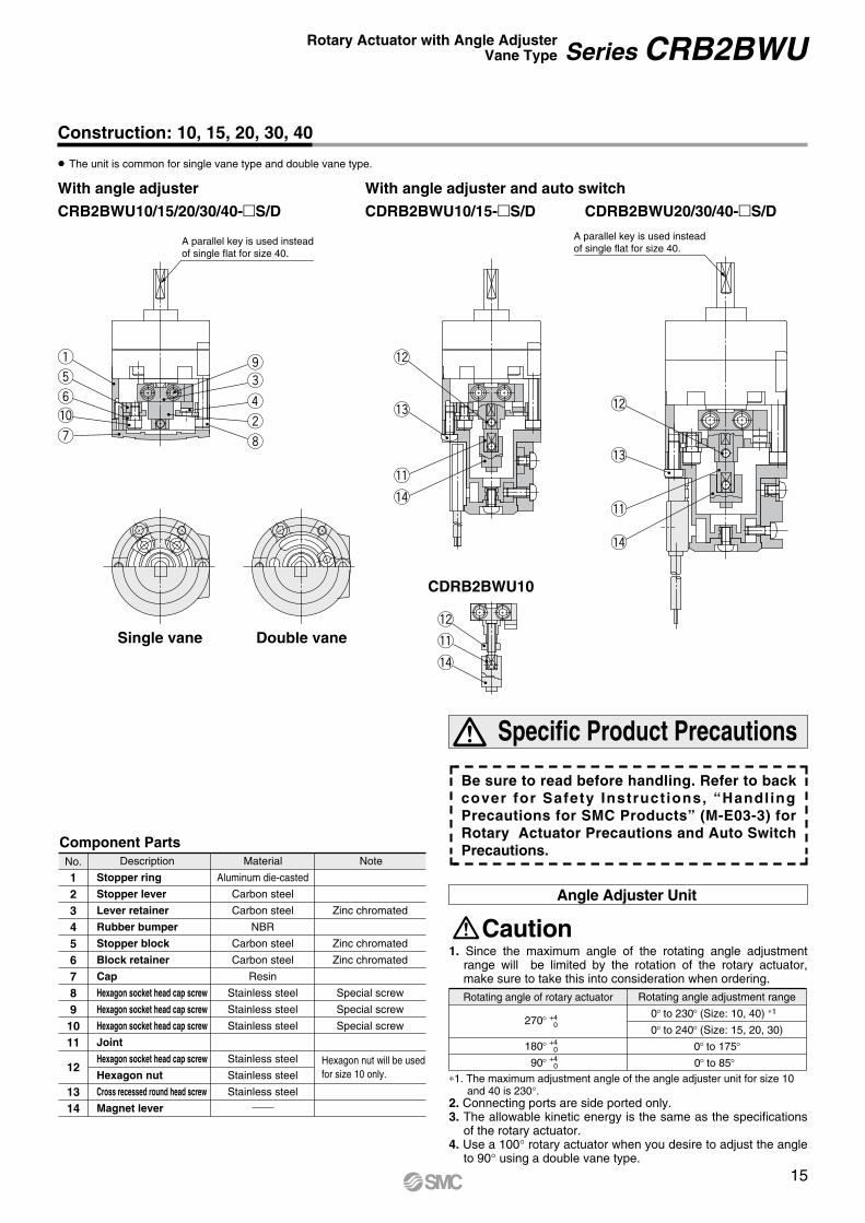
Component PartsNo.
1234567891011
12
1314
Description
Stopper ring
Stopper lever
Lever retainer
Rubber bumper
Stopper block
Block retainer
Cap
Hexagon socket head cap screw
Hexagon socket head cap screw
Hexagon socket head cap screw
Joint
Hexagon socket head cap screw
Hexagon nut
Cross recessed round head screw
Magnet lever
Aluminum die-casted
Carbon steel
Carbon steel
NBR
Carbon steel
Carbon steel
Resin
Stainless steel
Stainless steel
Stainless steel
Stainless steel
Stainless steel
Stainless steel
Zinc chromated
Zinc chromated
Zinc chromated
Special screw
Special screw
Special screw
Hexagon nut will be usedfor size 10 only.
Rotating angle of rotary actuator
270
1. The maximum adjustment angle of the angle adjuster unit for size 10 and 40 is 230 .
+40
180 +40
90 +40
1. Since the maximum angle of the rotating angle adjustment range will be limited by the rotation of the rotary actuator, make sure to take this into consideration when ordering.
2. Connecting ports are side ported only.3. The allowable kinetic energy is the same as the specifications
of the rotary actuator.4. Use a 100 rotary actuator when you desire to adjust the angle
to 90 using a double vane type.
Specific Product Precautions
Angle Adjuster Unit
Rotating angle adjustment range
0 to 230 (Size: 10, 40) 1
0 to 240 (Size: 15, 20, 30)
0 to 175
0 to 85
NoteMaterial
Be sure to read before handling. Refer to back cover for Safety Instructions, “Handling Precautions for SMC Products” (M-E03-3) for Rotary Actuator Precautions and Auto Switch Precautions.
CDRB2BWU20/30/40- S/D
With angle adjuster and auto switchWith angle adjuster
CRB2BWU10/15/20/30/40- S/D CDRB2BWU10/15- S/D
CDRB2BWU10
q
w
e
r
t
y
u i
o
!0
!1
!2
!3
!4!1
!2
!3
!4
!1
!2
!4
Construction: 10, 15, 20, 30, 40
The unit is common for single vane type and double vane type.
Caution
Single vane Double vane
15
Series CRB2BWURotary Actuator with Angle AdjusterVane Type
A parallel key is used instead of single flat for size 40.
A parallel key is used instead of single flat for size 40.
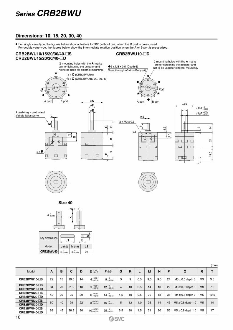
CRB2BWU10/15/20/30/40- SCRB2BWU15/20/30/40- D
CRB2BWU10- D
Model A
29
34
42
50
63
B
15
20
29
40
45
C
19.5
21.2
25
29
36.3
D G K L M N P Q R T
14
18
20
22
30
3
4
4.5
5
6.5
9
10
10
12
20
0.5
0.5
0.5
1.0
1.5
9.5
14
20
26
31
9.5
10
13
14
20
24
29
36
43
56
M3 x 0.5 depth 6
M3 x 0.5 depth 5
M4 x 0.7 depth 7
M5 x 0.8 depth 10
M5 x 0.8 depth 10
M3
M3
M5
M5
M5
3.6
7.6
10.5
14
17
E (g7) F (h9)
(mm)
CRB2BWU10- S
CRB2BWU15- SCRB2BWU15- DCRB2BWU20- SCRB2BWU20- DCRB2BWU30- SCRB2BWU30- DCRB2BWU40- SCRB2BWU40- D
4
5
6
8
10
−0.004−0.016
−0.004−0.016
−0.004−0.016
−0.005−0.020
−0.005−0.020
9
12
14
16
25
0−0.036
0−0.043
0−0.043
0−0.043
0−0.052
ø9h9 0−0.036
ø4g7 −0.004−0.016
L
2
20CRB2BWU40
h (h9) L1b (h9)
4 0
−0.030
4 0−0.030 4 0−0.030
L1 b
h
K
øP
L
H
9.5
3.6 3
0.5
6 x Q (CRB2BWU15, 20, 30, 40)
3 x Q (CRB2BWU10)
N
G
ø24
3 mounting holes with the marks are for tightening the actuator and
not to be used for external mounting.
(3 mounting holes with the marks are for tightening the actuator and not to be used for external mounting.)
3 x M3 x 0.5 (Depth 6)Goes through ø3.4 on Body (A)
Size 40
B portA port A port B port
K
2 x R
T
M
DB
C
øAøF
øE
2 x M3 x 0.5
9
9.5
ø29
4
1424
19.5
A parallel key is used instead of single flat for size 40.
Key dimensions
Model
Dimensions: 10, 15, 20, 30, 40
For single vane type, the figures below show actuators for 90 (without unit) when the B port is pressurized.For double vane type, the figures below show the intermediate rotation position when the A or B port is pressurized.
Series CRB2BWU
16

CDRB2BWU10/15- SCDRB2BWU15- D
CDRB2BWU20/30/40- S/D Size 40
Dimensions: 10, 15, 20, 30, 40 (The size 10 double vane type is indicated on page 18.)
For single vane type, the figures below show actuators for 90 (without unit) when the B port is pressurized.For double vane type, the figures below show the intermediate rotation position when the A or B port is pressurized.
Model A
29
34
42
50
63
B
15
20
29
40
45
C
45.5
47
51
55.5
62.2
D G K L M N P Q R T W Y
14
18
20
22
30
3
4
4.5
5
6.5
9
10
10
12
20
0.5
0.5
0.5
1.0
1.5
9.5
14
20
26
31
9.5
10
13
14
20
24
29
36
43
56
M3 x 0.5 depth 6
M3 x 0.5 depth 5
M4 x 0.7 depth 7
M5 x 0.8 depth 10
M5 x 0.8 depth 10
M3
M3
M5
M5
M5
3.6
7.6
10.5
14
17
19.8
21
22
24
30
18.5
18.5
25
25
31
E(g7) F(h9)
CDRB2BWU10- S
CDRB2BWU15- SCDRB2BWU15- DCDRB2BWU20- SCDRB2BWU20- DCDRB2BWU30- SCDRB2BWU30- DCDRB2BWU40- SCDRB2BWU40- D
4
5
6
8
10
−0.004−0.016
−0.004−0.016
−0.004−0.016
−0.005−0.020
−0.005−0.020
9
12
14
16
25
0−0.036
0−0.043
0−0.043
0−0.043
0−0.052
L2
20
Key dimensions
Model
CDRB2BWU40
h (h9) L1b (h9)
4 0
−0.030
4 0−0.030 4 0−0.030
L1 b
h
K
CDRB2BWU20/30- S/D CDRB2BWU40- S/D
R22.5
32.5
4
65
øP øP
8
L
6 x Q (CDRB2BWU15)3 x Q (CDRB2BWU10)
(26.5: Connector type)
(34.
5: C
onne
ctor
type
)
G
6 x Q60
(69
)2
A port B portA port B port
Auto switch
2 x R
K
N T
M24
(30
) 1
øY
CB
DG
øE
øFøA
Auto switch
2 x R25
.5M
TN
K
L
øY
CB
D
øE
øFøA
W
15
W
20.5
8
W
1. The length is 24 when any of the following auto switches are used: D-90/90A/S99(V)/T99(V)/S9P(V)The length is 30 when any of the following auto switches are used: D-97/93A
2. The angle is 60 when any of the following auto switches are used: D-90/90A/97/93AThe angle is 69 when any of the following auto switches are used: D-S99(V)/T99(V)/S9P(V)
(3 mounting holes with the marks are for tightening the actuator and not to be used for external mounting.)
A parallel key is used instead of single flat for size 40.
(mm)
17
Series CRB2BWURotary Actuator with Angle AdjusterVane Type
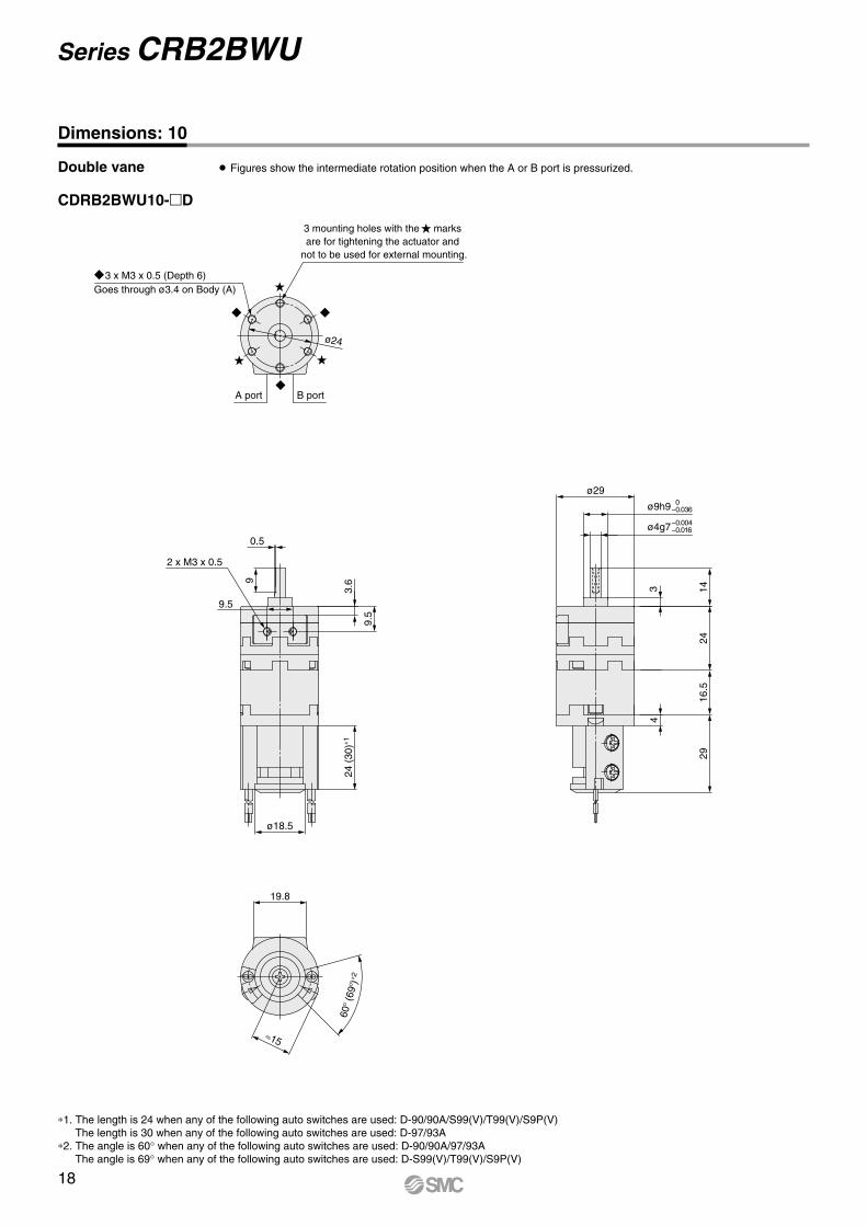
CDRB2BWU10- D
ø9h9 0−0.036
ø4g7−0.004−0.016
9.5
3
ø2460
(69
)2
2 x M3 x 0.5
0.5
9
3.6
9.5
24 (
30)
1
ø18.5
2916
.524
14
4
ø29
19.8
15
3 mounting holes with the marks are for tightening the actuator and
not to be used for external mounting.
A port B port
1. The length is 24 when any of the following auto switches are used: D-90/90A/S99(V)/T99(V)/S9P(V)The length is 30 when any of the following auto switches are used: D-97/93A
2. The angle is 60 when any of the following auto switches are used: D-90/90A/97/93AThe angle is 69 when any of the following auto switches are used: D-S99(V)/T99(V)/S9P(V)
3 x M3 x 0.5 (Depth 6)Goes through ø3.4 on Body (A)
18
Series CRB2BWU
Dimensions: 10
Double vane Figures show the intermediate rotation position when the A or B port is pressurized.
10
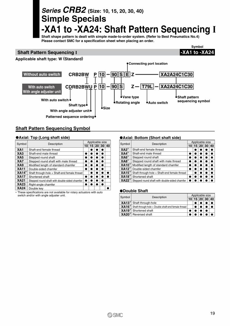
Auto switch
CDRB2BWU P 90 S T79L XA2A24C1C30
Size
With auto switch With angle adjuster unit
Shaft type
Applicable shaft type: W (Standard)
CRB2BW P 10 90 S E
Z
Z XA2A24C1C30Without auto switch
Vane type
Connecting port location
Shaft patternsequencing symbolRotating angle
Shaft Pattern Sequencing Symbol
Axial: Top (Long shaft side)
Patterned sequence ordering
Symbol DescriptionApplicable size
10 15 20 30 40
Double ShaftSymbol Description
Applicable size10 15 20 30 40
Axial: Bottom (Short shaft side)
Symbol DescriptionApplicable size
10 15 20 30 40
These specifications are not available for rotary actuators with auto switch and/or with angle adjuster unit.
Shaft-end female threadShaft-end male threadStepped round shaftStepped round shaft with male threadModified length of standard chamferDouble-sided chamferShaft through-hole + Shaft-end female threadShortened shaftStepped round shaft with double-sided chamferRight-angle chamferDouble key
Shaft-end female threadShaft-end male threadStepped round shaftStepped round shaft with male threadModified length of standard chamferDouble-sided chamferShaft through-hole + Shaft-end female threadShortened shaftStepped round shaft with double-sided chamfer
Shaft through-holeShaft through-hole + Double shaft-end female threadShortened shaftReversed shaft
With angle adjuster unit
With auto switch
XA1XA3XA5XA7XA9XA11XA14XA17XA21XA23XA24
XA2XA4XA6XA8XA10XA12XA15XA18XA22
XA13XA16XA19XA20
Series CRB2 (Size: 10, 15, 20, 30, 40)
Simple Specials-XA1 to -XA24: Shaft Pattern Sequencing IShaft shape pattern is dealt with simple made-to-order system. (Refer to Best Pneumatics No.4)Please contact SMC for a specification sheet when placing an order.
Symbol
-XA1 to -XA24Shaft Pattern Sequencing I
19

Combination
XA Combination
XA , XC Combination
A combination of up to two XA s are available.Example: -XA2A24
Combination other than -XA , such as Made to Order (-XC ), is also available.Refer to pages 29 to 30 for details on the made-to-order specifications.
SymbolXA1XA2XA3XA4XA5XA6XA7XA8XA9XA10XA11XA12XA13XA14XA15XA16XA17XA18XA19XA20XA21XA22XA23XA24
CombinationXA1
—
—
—
—
—
—————
———
——
XA2
—
—
—
—
—————
———
—
XA3
—
—
—
—
—————
———
——
XA4
—
—
—
—————
———
—
XA5
—
—
—
—————
———
——
XA6
—
—
—————
———
—
XA7
—
—
—————
———
——
XA8
—
—————
———
—
XA9
—
——
———
——
XA10
—
—
———
—
XA11
—————
———
——
XA12————
———
—
XA13————
———
—
XA14———
————
—
XA15—
—————
—
XA16——————
—
XA17
———
——
XA18——
—
XA19——
—
XA20
—
—
XA21
——
XA22XA22
—
XC1XC2XC3XC4XC5XC6XC7XC30
Add connecting portChange threaded holes to through-holesChange the screw positionChange rotation rangeChange rotation range between 0 to 200Change rotation range between 0 to 110Reversed shaftFluorine grease
10, 15, 20, 30, 4015, 20, 30, 40
CombinationXA1 to XA24
—
These specifications are not available for rotary actuators with auto switch and/or with angle adjuster unit. A total of four XA and XC combinations is available. Example: -XA2A24C1C30 -XA2C1C4C30
Symbol Description Applicable size
10, 15, 20, 30, 40
Series CRB2
20

Symbol: A1 The long shaft can be further shortened by machining female threads into it.
Size
15
20
30
X
(mm)
Q1
(If shortening the shaft is not required, indicate “ ” for dimension X.)Not available for size 10.The maximum dimension L1 is, as a rule, twice the thread size.(Example) For M3: L1 = 6 mm Applicable shaft type: W
Symbol: A2 The short shaft can be further shortened by machining female threads into it.
Size
15
20
30
40
Y(mm)
Q2
(If shortening the shaft is not required, indicate “ ” for dimension Y.) Not available for size 10.The maximum dimension L2 is, as a rule, twice the thread size.(Example) For M3: L2 = 6 mm Applicable shaft type: W
Symbol: A3 The long shaft can be further shortened by machining male threads into it.
Size
10
15
20
30
X
9 to 14
11 to 18
13 to 20
16 to 22
(mm)
L1 max
X-5
X-6
X-7
X-8
Q1
M4
M5
M6
M8
(If shortening the shaft is not required, indicate “ ” for dimension X.)Applicable shaft type: W
Axial: Top (Long shaft side) Axial: Bottom (Short shaft side)
Symbol: A4 The short shaft can be further shortened by machining male threads into it.
Size
10
15
20
30
40
Y 7 to 8
8.5 to 9
10
13
15
(mm)
L2 max
Y-3
Y-3.5
Y-4
Y-5
Y-6
Q2
M4
M5
M6
M8
M10
(If shortening the shaft is not required, indicate “ ” for dimension Y.)Applicable shaft type: W
Symbol: A5 The long shaft can be further shortened by machiningit into a stepped round shaft.
Size
10
15
20
30
X
4 to 14
5 to 18
6 to 20
6 to 22
(mm)
L1 max
X-3
X-4
X-4.5
X-5
D1
ø3
ø3 to ø4
ø3 to ø5
ø3 to ø6
(If shortening the shaft is not required, indicate “ ” for dimension X.)Applicable shaft type: WEqual dimensions are indicated by the same marker.(If not specifying dimension C1, indicate “ ” instead.)
Symbol: A6 The short shaft can be further shortened by machiningit into a stepped round shaft.
Size
10
15
20
30
40
Y
2 to 8
3 to 9
3 to 10
3 to 13
6 to 15
(mm)
L2 max
Y-1
Y-1.5
Y-1.5
Y-2
Y-4.5
D2
ø3
ø3 to ø4
ø3 to ø5
ø3 to ø6
ø3 to ø8
(If shortening the shaft is not required, indicate “ ” for dimension Y.)Applicable shaft type: WEqual dimensions are indicated by the same marker.(If not specifying dimension C2, indicate “ ” instead.)
Symbol: A7 The long shaft can be further shortened by machining it into a stepped round shaft with male threads.
Size
10
15
20
30
X
7.5 to 14
10 to 18
12 to 20
14 to 22
(mm)
L1 max
X-3
X-4
X-4.5
X-5
Q1
(If shortening the shaft is not required, indicate “ ” for dimension X.)Applicable shaft type: WEqual dimensions are indicated by the same marker.(If not specifying dimension C1, indicate “ ” instead.)
Symbol: A8 The short shaft can be further shortened by machining it into a stepped round shaft with male threads.
Size
10
15
20
30
40
Y
5.5 to 8
7.5 to 9
9 to 10
11 to 13
14 to 15
(mm)
L2 max
Y-1
Y-1.5
Y-1.5
Y-2
Y-4.5
Q2
(If shortening the shaft is not required, indicate “ ” for dimension Y.)Applicable shaft type: WEqual dimensions are indicated by the same marker.(If not specifying dimension C2, indicate “ ” instead.)
Q1= M
L1 +
(3
x P
)
L1 =
X =
Q2 = M L2 +
(3
x P
)
L2=
Y =
Q1 = M
L1
=
X =
Q2 = M
L2
=Y =
D1 = ø
C1
C1 = C
L1
=
X =
D2 = ø
L2
=
C2
C2 =
C
Y =
Q1 = MC1 = C
L1-(3
x P
)
X =
L1
=
Q2 = M
L2=
C2 =
C
L2-(3
x P
)
Y=
4 to 18
4.5 to 20
5 to 22
1.5 to 9
1.5 to 10
2 to 13
4.5 to 15
M3
M3, M4
M3, M4, M5
M3
M3, M4
M3, M4, M5
M3, M4, M5
3
3, 4
3, 4, 5
3, 4, 5, 6
3
3, 4
3, 4, 5
3, 4, 5, 6
3, 4, 5, 6, 8
Series CRB2Rotary ActuatorVane Type
21

Symbol: A9 The long shaft can be further shortened by changingthe length of the standard chamfer on the long shaft side.
Size
10
15
20
30
X
5 to 14
8 to 18
10 to 20
10 to 22
(mm)
L1
(If shortening the shaft is not required, indicate “ ” for dimension X.)Applicable shaft type: W
Symbol: A10 The short shaft can be further shortened by changing the length of the standard chamfer on the short shaft side.
Size
10
15
20
30
40
Y
3 to 8
3 to 9
3 to 10
5 to 13
7 to 15
(mm)
L2
(If shortening the shaft is not required, indicate “ ” for dimension Y.)Applicable shaft type: W
Symbol: A11 The long shaft can be further shortened by machininga double-sided chamfer onto it.
Size
10
15
20
30
X
5 to 14
8 to 18
10 to 20
10 to 22
(mm)
L1 L3 max
X-3
X-4
X-4.5
X-5
(If altering the standard chamfer and shortening the shaft are not required, indicate “ ” for both the L1 and X dimensions.)
Since L1 is a standard chamfer, dimension E1 is 0.5 mm or more,and 1 mm or more with a shaft bore size of ø30.Applicable shaft type: W
Axial: Top (Long shaft side) Axial: Bottom (Short shaft side)
Symbol: A12 The short shaft can be further shortened by machining a double-sided chamfer onto it.
Size
10
15
20
30
40
Y
3 to 8
3 to 9
3 to 10
5 to 13
7 to 15
(mm)
L2 L4 max
Y-1
Y-1.5
Y-1.5
Y-2
Y-4.5
(If altering the standard chamfer and shortening the shaft are not required, indicate “ ” for both the L2 and Y dimensions.)
Since L2 is a standard chamfer, dimension E2 is 0.5 mm or more, and 1 mm or more with shaft bore size of ø30 and ø40.
Applicable shaft type: W
Symbol: A14 Applicable to single vane type only
SizeThread
M3 x 0.5
M4 x 0.7
M5 x 0.8
15
ø2.5
—
—
(mm)
20
ø2.5
ø3.3
—
30
ø2.5
ø3.3
ø4.2
40
ø2.5
—
—
A special end is machined onto the long shaft, and a through-hole is drilled into it. Female threads are machined into the through-hole, whose diameter is equivalent to the pilot hole diameter.
Not available for size 10.The maximum dimension L1 is, as a rule, twice the thread size.
(Example) For M3: L1 max. = 6 mmA parallel key is used on the long shaft for size 40.Applicable shaft type: W
Symbol: A15 Applicable to single vane type onlyA special end is machined onto the short shaft, and a through-hole is drilled into it. Female threads are machined into the through-hole, whose diameter is equivalent to the pilot hole diameter.
A parallel key is used on the long shaft for size 40.Not available for size 10.The maximum dimension L2 is, as a rule, twice the thread size.
(Example) For M4: L2 max. = 8 mmApplicable shaft type: W
Symbol: A18 The short shaft is shortened.A parallel key is used on the long shaft for size 40.Applicable shaft type: W
X =
L1
=
L2
=
Y =
E3 =E1 =
L1
=
L3
=
X =
L4
=
L2
=
E4 =E2 =
Y=
Symbol: A17 The long shaft is shortened.Applicable shaft type: W
Size
10
15
20
30
40
X
3 to 14
4 to 18
4.5 to 20
5 to 22
18 to 33
(mm)
Size
10
15
20
30
40
Y
1 to 8
1.5 to 9
1.5 to 10
2 to 13
4.5 to 15
(mm)
M3 x 0.5
M4 x 0.7
M5 x 0.8
15
ø2.5
—
—
(mm)
20
ø2.5
ø3.3
—
30
ø2.5
ø3.3
ø4.2
40
ø2.5
—
—Q2 = M
L2 =
Q1 = M
L1 =
Body (A)
Body (B)
Long shaft side
Short shaft side
X =
Body (A)
Body (B)
Long shaft side
Short shaft side
Y=
9-(14-X) to (X-3)
10-(18-X) to (X-4)
10-(20-X) to (X-4.5)
12-(22-X) to (X-5)
5-( 8-Y) to (Y-1)
6-( 9-Y) to (Y-1.5)
7-(10-Y) to (Y-1.5)
8-(13-Y) to (Y-2)
9-(15-Y) to (Y-2)
9-(14-X) to (X-3)
10-(18-X) to (X-4)
10-(20-X) to (X-4.5)
12-(22-X) to (X-5)
5-( 8-Y) to (Y-1 )
6-( 2-Y) to (Y-1.5)
7-(10-Y) to (Y-1.5)
8-(13-Y) to (Y-2 )
9-(15-Y) to (Y-4.5)
Series CRB2
SizeThread
22

Symbol: A21 The long shaft can be further shortened by machining it into a stepped round shaft with a double-sided chamfer.
Size
10
15
20
30
X
6 to 14
7 to 18
8 to 20
10 to 22
L1 max
X-4.5
X-5.5
X-6.5
X-8
L3
L1 + 1.5
L1 + 1.5
L1 + 2
L1 + 3
D1(mm)
(If shortening the shaft is not required, indicate “ ” for dimension X.)Applicable shaft type: WEqual dimensions are indicated by the same marker.
(If not specifying dimension C1, indicate “ ” instead.)
Symbol: A22 The short shaft can be further shortened by machining it into a stepped round shaft with a double-sided chamfer.
Size
10
15
20
30
40
(mm)
(If shortening the shaft is not required, indicate “ ” for dimension Y.)Applicable shaft type: WEqual dimensions are indicated by the same marker.(If not specifying dimension C2, indicate “ ” instead.)
Axial: Top (Long shaft side)
Double Shaft
Axial: Bottom (Short shaft side)
Symbol: A13 Applicable to single vane type only
Size
15
20
30
40
d1(mm)
Shaft with through-holeNot available for size 10.Minimum machining diameter for d1 is 0.1 mm.A parallel key is used on the long shaft for size 40.Applicable shaft type: W
Symbol: A16 Applicable to single vane type onlyA special end is machined onto both the long and short shafts, and a through-hole is drilled into both shafts. Female threads are machined into the through-holes, whose diameter is equivalent to the diameter of the pilot holes.
Not available for size 10.The maximum dimension L1 is, as a rule, twice the thread size.
(Example) For M5: L1 max. = 10 mmA parallel key is used on the long shaft for size 40.Applicable shaft type: WEqual dimensions are indicated by the same marker.
Size Thread
M3 x 0.5
M4 x 0.7
M5 x 0.8
15
ø2.5
—
—
(mm)
20
ø2.5
ø3.3
—
30
ø2.5
ø3.3
ø4.2
40
ø2.5
—
—
d1 = ø
Q1 = M
Q1
L1=
L1
Symbol: A19 Both the long shaft and short shaft are shortened.
Size
10
15
20
30
40
X
3 to 14
4 to 18
4.5 to 20
5 to 22
18 to 30
Y
1 to 8
1.5 to 9
1.5 to 10
2 to 13
4.5 to 15
(mm)
A parallel key is used on the long shaft for size 40.Applicable shaft type: W
Symbol: A20 The shafts are reversed.(Both the long shaft and the short shaft are shortened.)
A parallel key is used on the long shaft for size 40.
Applicable shaft type: W
Size
10
15
20
30
40
X
3 to 10
4 to 11.5
4.5 to 13
5 to 16
6.5 to 17
(mm)
Y
1 to 12
1.5 to 15.5
1.5 to 17
2 to 19
—
Symbol: A23 The long shaft can be further shortened by machining right-angle double-sided chamfer onto it.
Size
10
15
20
30
X
5 to 14
8 to 18
10 to 20
10 to 22
L3 max
X-3
X-4
X-4.5
X-5
L1(mm)
(If altering the standard chamfer and shortening the shaft are not required, indicate “ ” for both the L1 and X dimensions.)
Since L1 is a standard chamfer, dimension E1 is 0.5 mm or more, and 1 mm or more with a shaft bore size of ø30 and ø40.
Applicable shaft type: W
Symbol: A24 Double keyKeys and keyways are machined additionally at 180 from the standard position.
Applicable shaft type: WEqual dimensions are indicated by the same marker.
Size
40
(mm)
Key dimensions
4 x 4 x 20
LL
2
Y
4 to 8
4.5 to 9
5 to 10
7 to 13
8 to 15
L1 max
Y-2.5
Y-3
Y-3.5
Y-5
Y-5.5
L4
L2 + 1.5
L2 + 1.5
L2 + 2
L2 + 3
L2 + 5
D2
ø3
ø3 to ø4
ø3 to ø5
ø3 to ø6
ø3 to ø6
D1 = ø
The standard chamfermay not be altered de-pending on the type of machining required.
The standard chamfer may not be altered depending on the type of machining required.
E1 =E3 =
L1
=
C1=
L3
=
X=
C1D2 = ø
E2 =E4 =
L4
=
C2
C2=
L2=
Y2
=
Body (A)
Body (B)
Long shaft side
Short shaft side Y=
X=
Body (A)
Body (B) X=
Y=
E1 =
E3
=
L1
=
L3
=
X =
LL
Key dimensions
LL
ø3
ø3 to ø4
ø3 to ø5
ø3 to ø6
ø2.5
ø2.5 to ø3.5
ø2.5 to ø4
ø2.5 to ø3
9- (14-X) to (X-3)
10- (18-X) to (X-4)
10- (20-X) to (X-4.5)
12- (22-X) to (X-5)
Series CRB2Rotary ActuatorVane Type
23

SJKTY
Refer topage 4.
Standard
Shaft Pattern Sequencing Symbol
Axial: Top (Long shaft side)
XA31XA33XA37XA45XA47XA48XA51
Description Shaft typeApplicable size
10 15 20 30 40 Shaft type
Double Shaft
Symbol DescriptionApplicable size
10 15 20 30 40
Axial: Bottom (Short shaft side)
Shaft-end female threadShaft-end female threadStepped round shaftMiddle-cut chamferMachined keywayChange of long shaft lengthChange of long shaft length
Shaft through-holeShaft through-holeShaft through-holeShaft through-hole + Shaft-end female threadShaft through-hole + Shaft-end female threadShaft through-hole + Shaft-end female threadChange of double shaft lengthChange of double shaft lengthChange of double shaft lengthReversed shaft, Change of double shaft length
Symbol
S, YJ, K, TJ, K, TJ, K, TJ, K, TS, Y
J, K, T
XA32XA34XA38XA46XA49XA52XA55
Description Shaft typeApplicable size
10 15 20 30 40Shaft-end female threadShaft-end female threadStepped round shaftMiddle-cut chamferChange of short shaft length Change of short shaft lengthChange of short shaft length
Symbol
S, YJ, K, T
KKYKJ
XA39XA40XA41XA42XA43XA44XA50XA53XA57XA58
S, YK, T
JS, YK, T
JYKJJ
These specifications are not available for rotary actuators with auto switch and/or with angle adjuster unit.
Series CRB2 (Size: 10, 15, 20, 30, 40)
Simple Specials-XA31 to -XA58: Shaft Pattern Sequencing IIShaft shape pattern is dealt with simple made-to-order system. (Refer to Best Pneumatics No.4)Please contact SMC for a specification sheet when placing an order.
10
Auto switch
U PCDRB2B 90 S T79L XA33A34C27C30
Size
With auto switch With angle adjuster unit
PCRB2B 10 90 S E
Z
Z XA33A34C27C30Without auto switch
Vane type
Connecting port location
J
J
Shaft type
Shaft pattern sequencing symbolRotating angle
Patterned sequence ordering
With angle adjuster unit
With auto switch
Applicable shaft type: S, J, K, T, Y
Symbol
-XA31 to -XA58Shaft Pattern Sequencing II
24

Combination
XA , XC CombinationCombination other than XA , such as Made to Order (XC ), is also available.Refer to pages 29 to 30 for details on the made-to-order specifications.
These specifications are not available for rotary actuators with auto switch and/or with angle adjuster unit.
A total of four XA and XC combinations is available.Example: XA33A34C5C30
XC1XC2XC3XC4XC5XC6XC7XC30
Description Applicable size
10, 15, 20, 30, 4015, 20, 30, 40
10, 15, 20, 30, 40
Add connecting portsChange threaded holes to through-holesChange the screw positionChange the rotation rangeChange rotation range between 0 to 200Change rotation range between 0 to 110Reversed shaftFluorine grease
Symbol
XA31XA32XA33XA34XA37XA38XA39XA40XA41XA42XA43XA44XA45XA46XA47XA48XA49XA50XA51XA52XA53XA55XA57XA58
XA31XA32
XA33XA34
XA37XA38
XA39
XA44XA45
XA46XA47
XA48XA49
XA50XA51
XA52XA53
XA55XA57
XA40XA41
XA42XA43
Y
K
K
J
K
J
KK,TKK
K,TKK
KKK
J
JJJ
J
JJJ
YY
KKJJJ
KKJJJ
YY
Shaft-end female threadShaft-end female threadShaft-end female threadShaft-end female threadStepped round shaftStepped round shaftShaft through-holeShaft through-holeShaft through-holeShaft through-hole + Shaft-end female threadShaft through-hole + Shaft-end female threadShaft through-hole + Shaft-end female threadMiddle-cut chamferMiddle-cut chamferMachined keywayChange of long shaft lengthChange of short shaft lengthChange of double shaft lengthChange of long shaft lengthChange of short shaft lengthChange of double shaft lengthChange of short shaft lengthChange of double shaft lengthReversed shaft, Change of double shaft length
XA Combination
A combination of up to two XA s are available.Example: XA31A32
Shaft type available for combination.
Symbol DescriptionAxial direction Applicable shaft type
CombinationJBottomTop K S T Y
J
KKJJJ J
Series CRB2Rotary ActuatorVane Type
CombinationXA31 to XA58
25
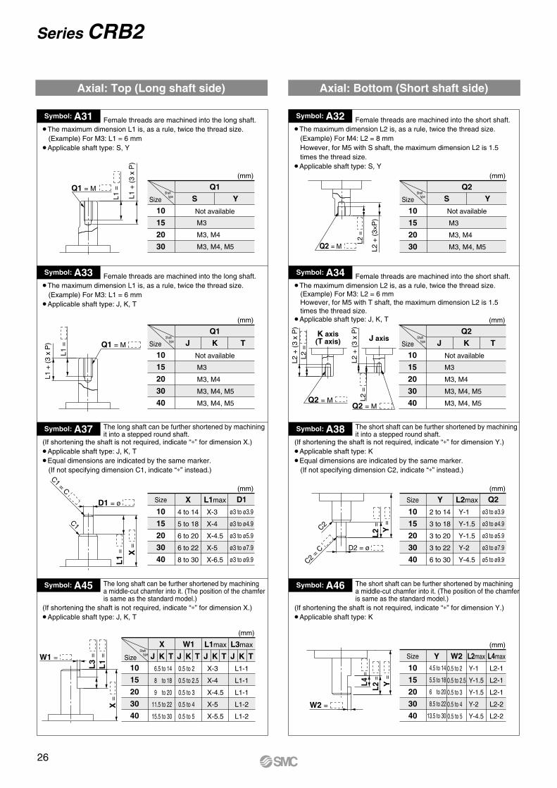
Series CRB2
Symbol: A31 Female threads are machined into the long shaft.
10
15
20
30
S
(mm)
YQ1
Size
Not available
The maximum dimension L1 is, as a rule, twice the thread size. (Example) For M3: L1 = 6 mm
Applicable shaft type: S, Y
Symbol: A32 Female threads are machined into the short shaft.The maximum dimension L2 is, as a rule, twice the thread size.
(Example) For M4: L2 = 8 mm However, for M5 with S shaft, the maximum dimension L2 is 1.5 times the thread size.
Applicable shaft type: S, Y
Symbol: A33 Female threads are machined into the long shaft.The maximum dimension L1 is, as a rule, twice the thread size.
(Example) For M3: L1 = 6 mmApplicable shaft type: J, K, T
Axial: Top (Long shaft side) Axial: Bottom (Short shaft side)
Symbol: A34 Female threads are machined into the short shaft.The maximum dimension L2 is, as a rule, twice the thread size.
(Example) For M3: L2 = 6 mm However, for M5 with T shaft, the maximum dimension L2 is 1.5 times the thread size.
Applicable shaft type: J, K, T
Symbol: A37 The long shaft can be further shortened by machiningit into a stepped round shaft.
Size
10
15
20
30
40
X
4 to 14
5 to 18
6 to 20
6 to 22
8 to 30
(mm)
L1max
X-3
X-4
X-4.5
X-5
X-6.5
D1
ø3 to ø3.9
ø3 to ø4.9
ø3 to ø5.9
ø3 to ø7.9
ø3 to ø9.9
(If shortening the shaft is not required, indicate “ ” for dimension X.)Applicable shaft type: J, K, TEqual dimensions are indicated by the same marker.
(If not specifying dimension C1, indicate “ ” instead.)
Symbol: A38 The short shaft can be further shortened by machiningit into a stepped round shaft.
Size
10
15
20
30
40
Y
2 to 14
3 to 18
3 to 20
3 to 22
6 to 30
(mm)
L2max
Y-1
Y-1.5
Y-1.5
Y-2
Y-4.5
Q2
ø3 to ø3.9
ø3 to ø4.9
ø3 to ø5.9
ø3 to ø7.9
ø5 to ø9.9
(If shortening the shaft is not required, indicate “ ” for dimension Y.)Applicable shaft type: KEqual dimensions are indicated by the same marker.(If not specifying dimension C2, indicate “ ” instead.)
Symbol: A45 The long shaft can be further shortened by machining a middle-cut chamfer into it. (The position of the chamferis same as the standard model.)
10
15
20
30
40
X(mm)
W1 L1max
X-3
X-4
X-4.5
X-5
X-5.5
L3max
L1-1
L1-1
L1-1
L1-2
L1-2
(If shortening the shaft is not required, indicate “ ” for dimension X.)Applicable shaft type: J, K, T
Symbol: A46 The short shaft can be further shortened by machining a middle-cut chamfer into it. (The position of the chamferis same as the standard model.)
Size
10
15
20
30
40
Y W2
0.5 to 2
0.5 to 2.5
0.5 to 3
0.5 to 4
0.5 to 5
(mm)
L2max
Y-1
Y-1.5
Y-1.5
Y-2
Y-4.5
L4max
L2-1
L2-1
L2-1
L2-2
L2-2
(If shortening the shaft is not required, indicate “ ” for dimension Y.)Applicable shaft type: K
10
15
20
30
40
J K
(mm)
TQ1
Size
Not available
10
15
20
30
S
(mm)
YQ2
Size
Not available
10
15
20
30
40
J K
(mm)
TQ2
Size
Not available
Q1 = M
L1 +
(3
x P
)
L1 =
Q2 = M L2 +
(3×
P)
L2 =
Q1 = M
L1 +
(3
x P
)
L1 =
Q2 = MQ2 = M
K axis(T axis) J axis
L2 +
(3
x P
)L2
=
L2 +
(3
x P
)L2
=
D1 = ø
C1 = C
C1
L1
= X= D2 = ø
L2
=
C2
C2 =
C
Y=
X=
L3
=W1 =
L1
= J K T J K T J K T J K TSize
W2 =
L4=
L2=
Y=
M3
M3, M4
M3, M4, M5
M3
M3, M4
M3, M4, M5
M3
M3, M4
M3, M4, M5
M3, M4, M5
M3
M3, M4
M3, M4, M5
M3, M4, M5
6.5 to 14
8 to 18
9 to 20
11.5 to 22
15.5 to 30
0.5 to 2
0.5 to 2.5
0.5 to 3
0.5 to 4
0.5 to 5
4.5 to 14
5.5 to 18
6 to 20
8.5 to 22
13.5 to 30
Shaft type
Shaft type
Shaft type
Shaft type
Shaft type
26

X=
X=
Y=
Y=
X=
Y=
Y=
Axial: Top (Long shaft side)
Double Shaft
Symbol: A39 Applicable to single vane type only
15
20
30
40
d1S Y
(mm)
Shaft with through-hole (Additional machining of S, Y shaft)Applicable shaft type: S, YEqual dimensions are indicated by
the same marker.Not available for size10.
A parallel key is used on the long shaft for size 40.
Minimum machining diameter for d1 is 0.1 mm.
Symbol: A40 Applicable to single vane type onlyShaft with through-hole (Additional machining of K, T shaft)
Applicable shaft type: K, TEqual dimensions are indicated by
the same marker.Not available for size10.
d1 = ø2.5, L1 = 18 (max.) for size 15 ; minimum machining diameter for d1 is 0.1 mm.
d1 = d3 for size 20 to 40.
S axisY axis
d1 = ø d1 = ø
Size
15
20
30
40
d1
ø2.5
d3K T K T
(mm)
Size
T axisK axis
L1 =
L2 =
d1
d3 = ø d3 = ø
d3
L1 =
d1
Shaft type Shaft type
Symbol: A47 Machine a keyway into the long shaft. (The positionof the keyway is the same as the standard model.) The key must be ordered separately.
Applicable shaft type: J, K, T
N1
a11.
5L
1
Axial: Bottom (Short shaft side)
Symbol: A49 The short shaft is shortened.
Applicable shaft type: Y
Symbol: A48 The long shaft is shortened.
Applicable shaft type: S, Y
Symbol: A52 The short shaft is shortened.
Applicable shaft type: K
Symbol: A51 The long shaft is shortened.
Applicable shaft type: J, K, T
Symbol: A55 The short shaft is shortened.
Applicable shaft type: J
ø2.5
ø2.5 to ø3.5
ø2.5 to ø4
ø2.5 to ø3
ø2.5 to ø3
ø2.5 to ø4
ø2.5 to ø4.5
ø2.5 to ø5
Size
10
15
20
30
40
Y(mm)
1 to 14
1.5 to 18
1.5 to 20
2 to 22
18 to 30
Size
10
15
20
30
40
Y(mm)
1 to 14
1.5 to 18
1.5 to 20
2 to 22
4.5 to 30
Size
10
15
20
30
40
Y(mm)
1 to 8
1.5 to 9
1.5 to 10
2 to 13
4.5 to 15
Size
10
15
20
30
40
X(mm)
3 to 14
4 to 18
4.5 to 20
5 to 22
18 to 30
Size
10
15
20
30
40
X(mm)
3 to 14
4 to 18
4.5 to 20
5 to 22
6.5 to 30
Size
20
30
a1
2h9
3h9
L1
10
14
N1
6.8
9.2
(mm)
0-0.025
0-0.025
Size 10 to 30 Size 40
Size 10 to 30 Size 40
Series CRB2Rotary ActuatorVane Type
27

Symbol: A41 Applicable to single vane type only
Size
15
20
30
40
d1(mm)
Shaft with through-hole• Not available for size 10.• Applicable shaft type: J• Equal dimensions are indicated by the same marker.
Symbol: A42 Applicable to single vane type onlyA special end is machined onto both the long and short shafts, and a through-hole is drilled into both shafts. Female threads are machined into the through-holes, whose diameter is equivalent to the diameter of the pilot holes.• Not available for size 10.• The maximum dimension L1 is, as a rule, twice the thread size.
(Example) For M5: L1 max. = 10 mm However, for M5 on the short shaft of S shaft: L1 max. = 7.5 mm
Symbol: A43 Applicable to single vane type onlyA special end is machined onto both the long and short shafts, and athrough-hole is drilled into both shafts. Female threads are machined into the through-holes, whose diameter is equivalent to the diameter of the pilot holes.• Not available for size 10.• The maximum dimension L1 is, as a rule, twice the thread size. (Example) For M5: L1 max. = 10 mm However, for M5 on the short shaft of T shaft: L1 max. = 7.5 mm
Symbol: A44 Applicable to single vane type onlyA special end is machined onto both the long and short shafts, and a through-hole is drilled into both shafts. Female threads are machined into the through-holes, whose diameter is equivalent to the diameter of the pilot holes.• Not available for size 10.• The maximum dimension L1 is, as a rule, twice the thread size. (Example) For M5: L1 max. = 10 mm
M3 x 0.5
M4 x 0.7
M5 x 0.8
S Y S Y S Y S Y
(mm)
15 20 30 40
Thread
SizeShaft
type
ø2.5
—
—
ø2.5
—
—
ø2.5
ø3.3
—
ø2.5
ø3.3
ø4.2
M3 x 0.5
M4 x 0.7
M5 x 0.8
K T K T K T K T
(mm)
15 20 30 40
Thread
ø2.5
—
—
ø2.5
ø3.3
ø4.2
ø2.5
ø3.3
—
ø2.5
ø3.3
ø4.2
M3 x 0.5
M4 x 0.7
M5 x 0.8
15 20 30 40Thread
Size
ø2.5
—
—
ø2.5
ø3.3
ø4.2
ø2.5
ø3.3
—
ø2.5
ø3.3
ø4.2
d1 = ø
• A parallel key is used on the longshaft for size 40.
• Applicable shaft type: S, Y• Equal dimensions are indicated
by the same marker.
Q1 = M
Q1
L1=
L1
• Applicable shaft type: K, T• Equal dimensions are indicated by the same marker.
Q1 = M
Q1
L1=
L1
• Applicable shaft type: J• Equal dimensions are indicated
by the same marker.
Q1 = M
Q1
L1=
L1
SizeShaft
type
Symbol: A50 Both the long shaft and the short shaft are shortened.
• Applicable shaft type: Y
Symbol: A53 Both the long shaft and the short shaft are shortened.
•Applicable shaft type: K
Symbol: A57 Both the long shaft and the short shaft are shortened.
• Applicable shaft type: J
Symbol: A58 The shafts are reversed. Additionally, both the long shaft and the short shaft are shortened.
(If shortening the shaft is not required, indicate “ ” for dimension X, Y.)• Applicable shaft type: J
ø2.5
ø2.5 to ø3.5
ø2.5 to ø4
ø2.5 to ø4.5
Size: 10 to 30 Size: 40
Y=
Y=
X =
X =
Short shaft side
Long shaft side
Body (B)
Body (A)
Short shaft side
Long shaft side
Body (B)
Body (A)
Y=
X =
Short shaft side
Long shaft side
Body (B)
Body (A)
Y =
X=
Short shaft side
Long shaft side
Body (B)
Body (A)
X=
Y=
Long shaft side
Short shaft side
Body (B)
Body (A)
Series CRB2
Size
10
15
20
30
40
X
3 to 14
4 to 18
4.5 to 20
5 to 22
18 to 30
(mm)
Y
1 to 14
1.5 to 18
1.5 to 20
2 to 22
18 to 30
Size
10
15
20
30
40
X
3 to 14
4 to 18
4.5 to 20
5 to 22
6.5 to 30
(mm)
Y
1 to 14
1.5 to 18
1.5 to 20
2 to 22
4.5 to 30
Size
10
15
20
30
40
X
3 to 14
4 to 18
4.5 to 20
5 to 22
6.5 to 30
(mm)
Y
1 to 14
1.5 to 18
1.5 to 20
2 to 22
4.5 to 30
Size
10
15
20
30
40
X
3 to 10
4 to 11.5
4.5 to 13
5 to 16
6.5 to 17
(mm)
Y
1 to 12
1.5 to 15.5
1.5 to 17
2 to 19
4.5 to 28
28

Made to Order Symbol
XC1 XC2 XC3 XC4 XC5 XC6 XC7XC30
Description
Add connecting portsChange threaded holes to through-holesChange the screw positionChange the rotation rangeChange rotation range between 0 to 200Change rotation range between 0 to 110Reversed shaftFluorine grease
Applicablesize
10
15
20
30
40
Applicable shaft typeW, J, K, S, T, Y
W, J
These specifications are not available for rotary actuators with auto switch and/or angle adjuster unit.
Combination
XC1XC2XC3XC4XC5XC6XC7
XC30
Combination
SWJKTY
Standard
Refer topage 4.
Shaft typeWJ
Standard
Refer to page 4.
XC1XC2
XC3XC4
XC5XC6
XC7
SymbolSymbol
Series CRB2 (Size 10, 15, 20, 30, 40)
Made to Order-XC1, 2, 3, 4, 5, 6, 7, 30
10
Auto switch
U PCDRB2B 90 S T79L XC1C30
Size
With auto switch With angle adjuster unit
PCRB2B 10 90 S E
Z
Z XC1C30Without auto switch
Vane type
Connecting port location
J
J
Shaft type
Made-to-order symbol
Rotating angle
With angle adjuster unit
With auto switch
Symbol
-XC1 to -XC7, -XC30
Patterned sequence ordering
29
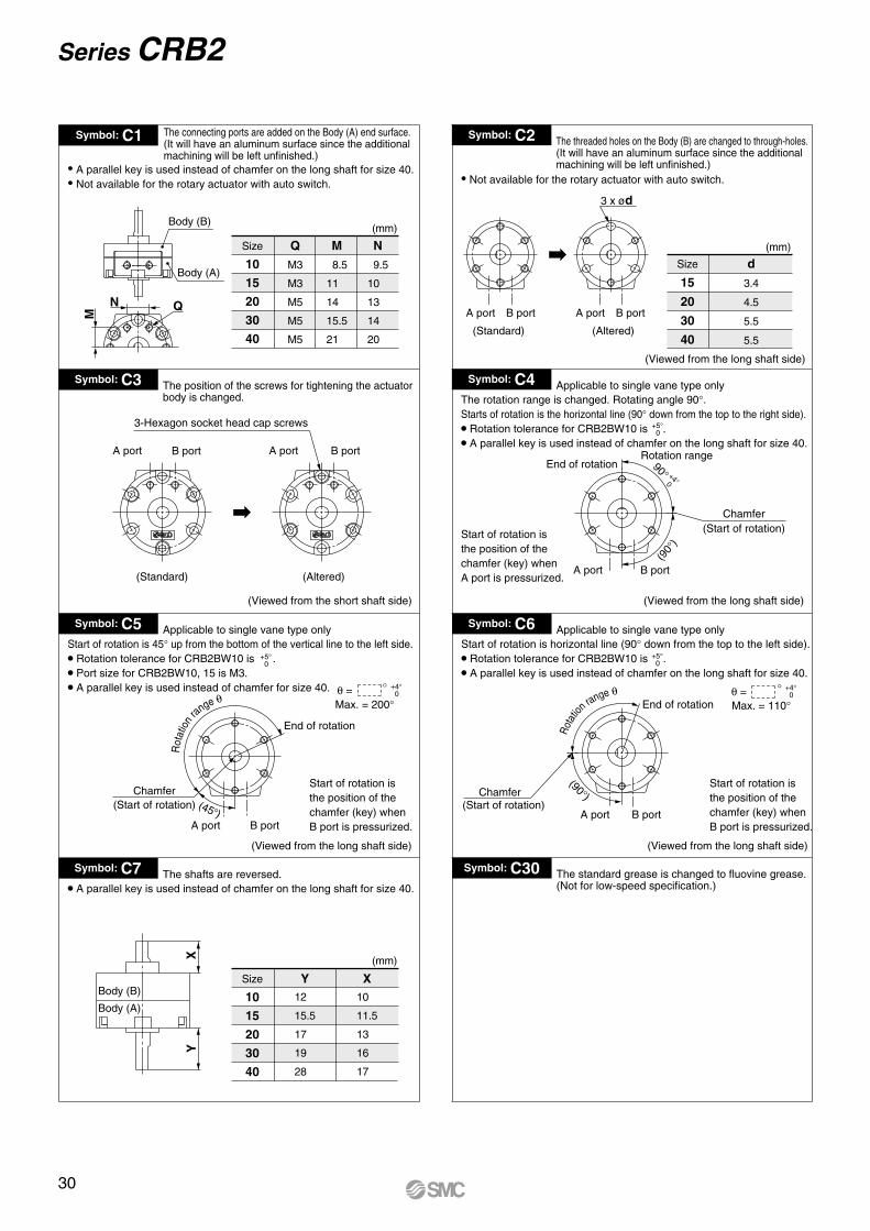
Symbol: C1 The connecting ports are added on the Body (A) end surface.(It will have an aluminum surface since the additional machining will be left unfinished.)
Size
10
15
20
30
40
(mm)
Q
M3
M3
M5
M5
M5
M
8.5
11
14
15.5
21
N
9.5
10
13
14
20
A parallel key is used instead of chamfer on the long shaft for size 40. Not available for the rotary actuator with auto switch.
Symbol: C2 The threaded holes on the Body (B) are changed to through-holes.(It will have an aluminum surface since the additional machining will be left unfinished.)
Not available for the rotary actuator with auto switch.
Size
15
20
30
40
(mm)
d
3.4
4.5
5.5
5.5
A port
(Standard) (Altered)
(Viewed from the long shaft side)
B port A port B port
3 x ød
Symbol: C3 The position of the screws for tightening the actuator body is changed.
(Viewed from the short shaft side) (Viewed from the long shaft side)
Symbol: C4 Applicable to single vane type onlyThe rotation range is changed. Rotating angle 90 .Starts of rotation is the horizontal line (90 down from the top to the right side).
• Rotation tolerance for CRB2BW10 is .
• A parallel key is used instead of chamfer on the long shaft for size 40.
Start of rotation is the position of the chamfer (key) when A port is pressurized.
(Viewed from the long shaft side)
Start of rotation is the position of the chamfer (key) when B port is pressurized.
(Viewed from the long shaft side)
Symbol: C5 Applicable to single vane type onlyStart of rotation is 45 up from the bottom of the vertical line to the left side.
• Rotation tolerance for CRB2BW10 is .
• Port size for CRB2BW10, 15 is M3.
• A parallel key is used instead of chamfer for size 40.
Symbol: C6 Applicable to single vane type onlyStart of rotation is horizontal line (90 down from the top to the left side).
• Rotation tolerance for CRB2BW10 is .
• A parallel key is used instead of chamfer on the long shaft for size 40.
Symbol: C7 The shafts are reversed.
Size
10
15
20
30
40
Y(mm)
X
• A parallel key is used instead of chamfer on the long shaft for size 40.
Symbol: C30 The standard grease is changed to fluovine grease.(Not for low-speed specification.)
+5 0
+5 0
+5 0
A port B port
(Standard) (Altered)
A port B port
3-Hexagon socket head cap screws
A port B port
Chamfer(Start of rotation)
End of rotationRotation range
(90
)
90+4 0
End of rotation
A port B port
(45 )
Chamfer(Start of rotation)
End of rotation
A port B port
Chamfer(Start of rotation)
(90)
Body (B)
Body (A)
XY
+4 0 =
Max. = 200
+4 0=
Max. = 110
10
11.5
13
16
17
12
15.5
17
19
28
Series CRB2M
N Q
Body (A)
Body (B)
Rot
atio
n range
Start of rotation isthe position of thechamfer (key) whenB port is pressurized.
Rota
tio
n range
30

31

Rotary Actuator
Series CRB2Component Unit
Auto Switch Unit and Angle Adjuster Unit
Series CRB2 Auto switch unit and/or angle adjuster unit can be mounted on the rotary actuator vane type.
Rotary actuator with auto switch unitCDRB2BW - -
Rotary actuator with auto switch unit and angle adjuster unitCDRB2BWU - -
Rotary actuator with angle adjuster unitCRB2BWU - -
Retrofit unit Auto switch unit Retrofit unit Angle adjuster unit
Retrofit unit Auto switch unit/Angle adjuster unit
The rotary actuator with auto switch and angle adjuster is basically a combination of the auto switch unit and angle adjuster unit.The items marked with are additional parts required for connection (joint assembly parts), and the items marked with are unnecessary.
To order the joint assembly separately, order it using the joint unit part number.
Auto switch unit Angle adjuster unit
Single flat (key)Round head screw
Single flat (key)
Cap
Single flat (key)
Set screw Joint
Round head screw
32

1 Auto Switch Unit Part No.
Series Vane type
Single/Double
Model
CDRB2BW10
CDRB2BW15
CDRB2BW20
CDRB2BW30
CDRB2BW40
Unit part no.
P611070-1
P611090-1
P611060-1
P611080-1
P611010-1
CRB2
Each unit can be retrofitted to the rotary actuator.
3 Angle Adjuster Unit Part No.
Series Vane type
Single/Double
Model
CRB2BWU10
CRB2BWU15
CRB2BWU20
CRB2BWU30
CRB2BWU40
Unit part no.
P811010-3
P811020-3
P811030-3
P811040-3
P811050-3
CRB2
Each unit can be retrofitted to the rotary actuator.
4 Auto Switch Angle Adjuster Unit Part No.
Series Vane type
Single/Double
Model
CDRB2BWU10
CDRB2BWU15
CDRB2BWU20
CDRB2BWU30
CDRB2BWU40
Unit part no.
P811010-4
P811020-4
P811030-4
P811040-4
P811050-4
CRB2
Each unit can be retrofitted to the rotary actuator.
5 Joint Unit Part No.
Series Vane type
Single/Double
Model
CDRB2BWU10
CDRB2BWU15
CDRB2BWU20
CDRB2BWU30
CDRB2BWU40
Unit part no.
P211070-10
P211090-10
P211060-10
P211080-10
P211010-10
CRB2
Joint unit is required to retrofit the angle adjuster unit to a rotary actuator with auto switch or to retrofit the auto switch unit to a rotary actuator with angle adjuster.
2 Switch Block Unit Part No.
Series
Right-handed
Left-handed
Right-handed
Left-handed
Right-handed
Left-handed
Model Unit part no.
P611070-8
P611070-9
P611010-8
P611010-9
P611060-8CRB2
CDRB2BW10,15
CDRB2BW20,30
CDRB2BW40
Auto switch unit comes with one right-hand and one left-hand switch blocks that are used for addition or when the switch block is damaged.
Solid state switch for size 10 and 15 requires no switch block, therefore the unit part number will be P211070-13.
Auto switch unit can be ordered separately if the rotary actuator with auto switch is required after the product being delivered. Since the auto switch will not be included, please order separately.
33
Component Unit Series CRB2

SpecificationsSingle Vane
Double Vane
ModelCRB2BWU10CRB2BWU15CRB2BWU20CRB2BWU30CRB2BWU40
Rotating angle adjustment range0 to 230
0 to 240
0 to 230
Rubber bumper
Yes
Rotating Angle Adjustment Method
Recommended Tightening Torque for Holding Stopper Block
ModelCRB2BWU10CRB2BWU15CRB2BWU20CRB2BWU30CRB2BWU40
Tightening torque (N·m)
1.0 to 1.2
2.5 to 2.9
3.4 to 3.9
ModelCRB2BWU10CRB2BWU15CRB2BWU20CRB2BWU30CRB2BWU40
Rotating angle adjustment range
0 to 90
Rubber bumper
YesRotaryactuator
Remove the resin cap in the illustrations below, slide the stopper block on the long groove and lock it into the appropriate position to adjust the rotating angle and rotating position. Protruding four chamfers for wrench on the output shaft that rotates allows manual operation and convenient position-ing. (Refer to the rotating angle setting examples shown in the next page for details.)
Other Operating Method
Although one stopper block is mounted on each long groove for standard specifications as shown in the illustrations below, 2 stopper blocks can be mounted on one long groove.
Angle adjustment range when 2 stopper blocks are mounted on one long grooveSize: 10, 40 ··················50Size: 15, 20, 30 ············60
As shown in <Fig.b>, when mounting 2 stopper blocks on one long groove, by revolving each stopper block (A)(B), the rotation range of the output shaft with single flat (key) is adjustable, as described in <Fig.a>,within either left 50 or 60 against port A and B.(Rotation range of single flat (key) when mounting 2 stopper blocks on the other side’s groove is the opposite side from <Fig.a> and the setting range is within either right 50 or 60 against port A and B.)
Series CRB2Angle Adjustment Setting
Note 1) Since the maximum angle of the rotating angle adjustment range will be limited by the rotation when using a rotary actuator for 90 ,make sure to take this into consideration when ordering. Rotary actuator for 90 should be used to adjust the angle of 85 or less as a guide.
Note 2) Connecting ports are side ported only.Note 3) The allowable kinetic energy is the same as the specifications of
the rotary actuator.
Note) Stopper block is tightened temporarily at the time of shipment. Angle is not adjusted before shipment.
60 50
Note) For size 40, each stopper block comes with 2 holding screws.
Section A-A(Double vane)
<Fig. b>
<Fig. a>
Section A-A(Single vane)
A A
Angle adjuster unit
Stopper block Long groove
Long grooveStopper block
Four chamfersfor wrench
Output shaft with single flat(A key is used for size 40.)
B portA port
Cap
Single flat (key)
A port B port
B portA port
Stopper lever
Stopper block (A) Stopper block (B)
Note 1) Use rotary actuator for 270 .Note 2) Connecting ports are side ported only.Note 3) The allowable kinetic energy is the same as the specifications of
the rotary actuator.
34

(195 )
(270 )
(135
)
Set range of BlockMax. 115 (Size: 10, 40)Max. 120 (Size: 15, 20, 30)
Set range of BlockMax. 115 (Size: 10, 40)
Max. 120 (Size: 15, 20, 30)
End qEnd w
<Fig. 4-2><Fig. 3-2>
End w
End q
<Fig. 4-1><Fig. 3-1>
<Fig. 2-2>
End w
End q
<Fig. 2-1><Fig. 1-1>
Point zero
Counterclockwise
Clockwise
Counterclockwise
Clockwise
Counterclockwise
Clockwise
Counterclockwise<Fig. 1-2>
Clockwise
End wEnd q
Single flat
A port B port
B portA port
Hatched area representsa stopper lever.
Stopper ring
Set range of Block = 135
Set range ofBlock = 90
A port B port
B portA port
Stopper ring
Single flat
Stopper ring
B portA port
B portA port
Single flat
Set range ofBlock = 30
Single flat
A port
A port
B port
Set range of Block = 90
B port
Stopper ring
End r
End e
(45 )
(45 )(45 )
Rotating Angle Setting Examples
The stopper ring is mounted on the standard position.(Rotary actuator with a rotating angle of 270 is used.)
Example 1 Example 2
Lock Block in Fig. 1-2, and move Block clockwise to allow the rotation of the shaft with single flat in Fig. 1-1 from point zero to End q. When Blockis locked and Block is moved counterclockwise, the shaft with single flat in Fig. 1-1 rotates from point zero to End w. The maximum rotation range of the shaft with single flat is as follows: Sizes 10, 40: up to 230 ; Sizes 15, 20, 30: up to 240 (Fig. 1-2 shows when the rotating angle is 0 .)
The maximum rotation range of the shaft with single flat in Fig. 2-2 is 195 ,from End q to End w. The rotation range of the shaft with single flat in Fig. 2-1 decreases to the range between End w and e when moving Blockin Fig. 2-2 clockwise, and similarly when moving Block counterclockwise, the rotation range decreases to the range between End q and r.However, since the internal stopper will come into contact with the vane at End q position of the shaft with single flat in Fig. 2-1, make sure that the stopper lever stops at Block when adjusting.
Example 3The stopper ring is mounted on 120 clockwise from the standard position shown in Fig. 1-2 of Example 1 as in Fig. 4-2 of Example 4.
Lock Block in Fig. 3-2 and move Block counterclockwise to allow the rotation of the shaft with single flat in Fig. 3-1 from End q to End w.However, since the internal stopper will come into contact with the vane at End q position of the shaft with single flat make sure that the stopper lever stops at Block when adjusting. End q side can be adjusted within 30 bymoving Block counterclockwise.
The stopper ring is mounted on 120 clockwise from the standard position shown in Fig. 1-2 of Example 1 as in Fig. 3-2 of Example 3.
The maximum rotation range of the shaft with single flat is 270 , from End q to End w, when using the actuator for 270 and End q side in Fig. 4-1 is stopped using the internal stopper and End w side is adjusted using Block .The rotation range can be adjusted within 90 in End w side. Note that Block cannot be moved and set 90 or more counterclockwise from its position in Fig. 4-2 since the internal stopper will come into contact with the vane.
Example 4
Note 1) Mounting of the stopper ring shown in Examples 2, 3, 4 are not applicable for size 10.Note 2) marks in the illustrations above indicate the mounting position of the stopper ring.Note 3) Select the appropriate rotation of the rotary actuator after careful consideration of the content of “Angle Adjustment Setting”.Note 4) For size 40, each block comes with 2 holding screws.
Block
Block
BlockBlock
Block
Block
Block
The stopper ring is mounted on 120 counterclockwise from the standard position shown in Fig. 1-2 of Example 1.
35
Angle Adjustment Setting Series CRB2

Applicable Auto Switches
Applicable series Auto switch model Electrical entry
CDRB2BW10/15
CDRB2BW20/30/40
Reed
Solidstate
Reed
Solidstate
D-90/90A
D-97/93A
D-S99/S99V
D-S9P/S9PV
D-T99/T99V
D-R73
D-R80
D-S79
D-S7P
D-T79
Grommet, 2-wire
Grommet, 3-wire (NPN)
Grommet, 3-wire (PNP)
Grommet, 2-wire
Grommet, 2-wire
Connector, 2-wire
Grommet, 3-wire (NPN)
Grommet, 3-wire (PNP)
Grommet, 2-wire; Connector, 2-wire
Operating Range and Hysteresis
Operating range: mThe range between the position where the auto switch turns ON as the magnet inside the auto switch unit moves and the position where the switch turns OFF as the magnet travels the same direction.Hysteresis range: dThe range between the position where the auto switch turns ON as the magnet inside the auto switch unit moves and the position where the auto switch turns OFF as the magnet travels the opposite direction.
How to Change the Auto Switch Detecting Position
When setting the detecting position, loosen the tightening screw a bit and move the auto switch to the preferred position and then tighten again and fix it. At this time, if tightened too much, screw can become damaged and unable to fix position. Be sure to set the tightening torque around 0.49 N·m.
Note) Since the figures in the above table are provided as a guideline only, they cannot be guaranteed.Adjust the auto switch after confirming the operating conditions in the actual setting.
Auto switch
Magnet
OFF
(OFF)
CDRB2BW10/15 CDRB2BW20 to 40
d: Hysteresis range
Actuated position: ON
m: Operating range
Model m: Operating range110 90 52
d: Hysteresis range
10
8
Solid state switch with 3-wire type has no connector type.
CDRB2BW10/15CDRB2BW20/30CDRB2BW40
Set screw
Series CDRB2With Auto Switch
36
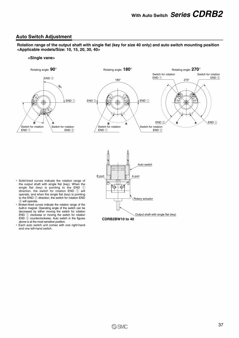
Rotation range of the output shaft with single flat (key for size 40 only) and auto switch mounting position<Applicable models/Size: 10, 15, 20, 30, 40>
Solid-lined curves indicate the rotation range of the output shaft with single flat (key). When the single flat (key) is pointing to the END qdirection, the switch for rotation END q will operate, and when the single flat (key) is pointing to the END w direction, the switch for rotation END w will operate.Broken-lined curves indicate the rotation range of the built-in magnet. Operating angle of the switch can be decreased by either moving the switch for rotation END q clockwise or moving the switch for rotation END w counterclockwise. Auto switch in the figures above is at the most sensitive position.
Each auto switch unit comes with one right-hand and one left-hand switch.
<Single vane>
CDRB2BW10 to 40
90
ABABB A
180 270
Rotating angle: 90 Rotating angle: 180 Rotating angle: 270
END w END q
END w
END q
Auto switch
A port
Rotary actuator
Output shaft with single flat (key)
B port
Switch for rotationEND q
Switch for rotationEND q
Switch for rotationEND q
Switch for rotationEND w
Switch for rotationEND w
Switch for rotationEND w
END w END q
37
Auto Switch Adjustment
With Auto Switch Series CDRB2

1st printing QT printing QT 8100SZ Printed in Japan.
Akihabara UDX 15F, 4-14-1, Sotokanda, Chiyoda-ku, Tokyo 101-0021, JAPANPhone: 03-5207-8249 Fax: 03-5298-5362http://www.smcworld.com© 2012 SMC Corporation All Rights Reserved
D-DNSpecifications are subject to change without prior notice and any obligation on the part of the manufacturer.
Warning
Limited warranty and Disclaimer/Compliance Requirements The product used is subject to the following “Limited warranty and Disclaimer” and “Compliance Requirements”.Read and accept them before using the product.
1. The product is provided for use in manufacturing industries.The product herein described is basically provided for peaceful use in manufacturing industries. If considering using the product in other industries, consult SMC beforehand and exchange specifications or a contract if necessary. If anything is unclear, contact your nearest sales branch.
Caution
Limited warranty and Disclaimer1. The warranty period of the product is 1 year in service or 1.5
years after the product is delivered. 2)
Also, the product may have specified durability, running distance or replacement parts. Please consult your nearest sales branch.
2. For any failure or damage reported within the warranty period which is clearly our responsibility, a replacement product or necessary parts will be provided. This limited warranty applies only to our product independently, and not to any other damage incurred due to the failure of the product.
3. Prior to using SMC products, please read and understand the warranty terms and disclaimers noted in the specified catalog for the particular products.
2) Vacuum pads are excluded from this 1 year warranty.A vacuum pad is a consumable part, so it is warranted for a year after it is delivered. Also, even within the warranty period, the wear of a product due to the use of the vacuum pad or failure due to the deterioration of rubber material are not covered by the limited warranty.
Compliance Requirements1. The use of SMC products with production equipment for the
manufacture of weapons of mass destruction (WMD) or any other weapon is strictly prohibited.
2. The exports of SMC products or technology from one country to another are governed by the relevant security laws and regulations of the countries involved in the transaction. Prior to the shipment of a SMC product to another country, assure that all local rules governing that export are known and followed.
These safety instructions are intended to prevent hazardous situations and/or equipment damage. These instructions indicate the level of potential hazard with the labels of “Caution,” “Warning” or “Danger.” They are all important notes for safety and must be followed in addition to International Standards (ISO/IEC) 1), and other safety regulations.
1) ISO 4414: Pneumatic fluid power – General rules relating to systems. ISO 4413: Hydraulic fluid power – General rules relating to systems. IEC 60204-1: Safety of machinery – Electrical equipment of machines. (Part 1: General requirements) ISO 10218-1: Manipulating industrial robots - Safety. etc.
Safety Instructions
Safety Instructions Be sure to read “Handling Precautions for SMC Products” (M-E03-3) before using.
Caution indicates a hazard with a low level of risk which, if not avoided, could result in minor or moderate injury.
Warning indicates a hazard with a medium level of risk which, if not avoided, could result in death or serious injury.
Caution:
Warning:
Danger :Danger indicates a hazard with a high level of risk which, if not avoided, will result in death or serious injury.
1. The compatibility of the product is the responsibility of theperson who designs the equipment or decides its specifications.Since the product specified here is used under various operating conditions, its compatibility with specific equipment must be decided by the person who designs the equipment or decides its specifications based on necessary analysis and test results. The expected performance and safety assurance of the equipment will be the responsibility of the person who has determined its compatibility with the product. This person should also continuously review all specifications of the product referring to its latest catalog information, with a view to giving due consideration to any possibility of equipment failure when configuring the equipment.
2. Only personnel with appropriate training should operate machinery and equipment.The product specified here may become unsafe if handled incorrectly. The assembly, operation and maintenance of machines or equipment including our products must be performed by an operator who is appropriately trained and experienced.
3. Do not service or attempt to remove product and machinery/equipment until safety is confirmed.1. The inspection and maintenance of machinery/equipment should only
be performed after measures to prevent falling or runaway of the driven objects have been confirmed.
2. When the product is to be removed, confirm that the safety measures as mentioned above are implemented and the power from any appropriate source is cut, and read and understand the specific product precautions of all relevant products carefully.
3. Before machinery/equipment is restarted, take measures to prevent unexpected operation and malfunction.
4. Contact SMC beforehand and take special consideration ofsafety measures if the product is to be used in any of the following conditions.1. Conditions and environments outside of the given specifications, or use
outdoors or in a place exposed to direct sunlight.2. Installation on equipment in conjunction with atomic energy, railways,
air navigation, space, shipping, vehicles, military, medical treatment, combustion and recreation, or equipment in contact with food and beverages, emergency stop circuits, clutch and brake circuits in press applications, safety equipment or other applications unsuitable for the standard specifications described in the product catalog.
3. An application which could have negative effects on people, property, or animals requiring special safety analysis.
4. Use in an interlock circuit, which requires the provision of double interlock for possible failure by using a mechanical protective function, and periodical checks to confirm proper operation.