ross syscon control panels - chemical processing · pdf fileross syscon control panels...
TRANSCRIPT
Page 1 of 14
Phone: 912-238-5800 - Website: www.rosssyscon.com - E-mail: [email protected]
Ross SysCon Control Panels
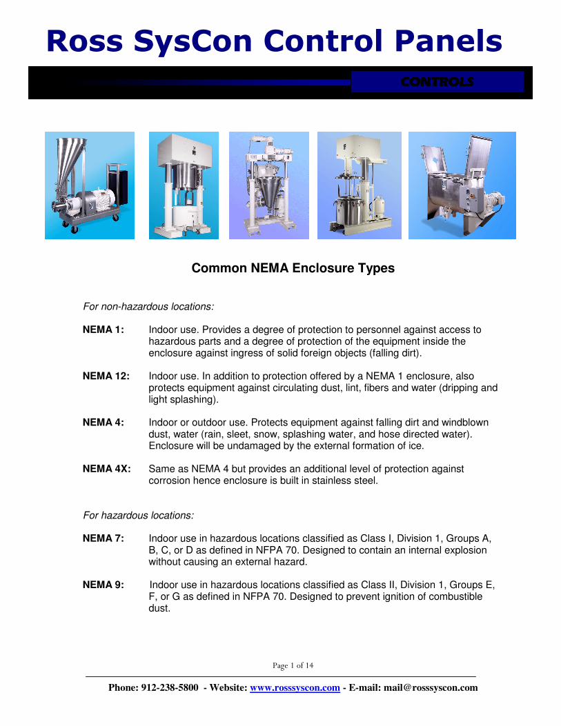
Common NEMA Enclosure Types
For non-hazardous locations:
NEMA 1: Indoor use. Provides a degree of protection to personnel against access to
hazardous parts and a degree of protection of the equipment inside the enclosure against ingress of solid foreign objects (falling dirt).
NEMA 12: Indoor use. In addition to protection offered by a NEMA 1 enclosure, also
protects equipment against circulating dust, lint, fibers and water (dripping and light splashing).
NEMA 4: Indoor or outdoor use. Protects equipment against falling dirt and windblown
dust, water (rain, sleet, snow, splashing water, and hose directed water). Enclosure will be undamaged by the external formation of ice.
NEMA 4X: Same as NEMA 4 but provides an additional level of protection against
corrosion hence enclosure is built in stainless steel. For hazardous locations:
NEMA 7: Indoor use in hazardous locations classified as Class I, Division 1, Groups A,
B, C, or D as defined in NFPA 70. Designed to contain an internal explosion without causing an external hazard.
NEMA 9: Indoor use in hazardous locations classified as Class II, Division 1, Groups E,
F, or G as defined in NFPA 70. Designed to prevent ignition of combustible dust.
CONTROLSCONTROLSCONTROLSCONTROLS
Page 2 of 14
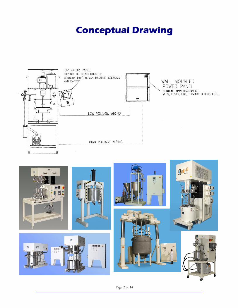
Conceptual Drawing

Page 3 of 14
Control Panel + Motor Starter (Single Speed Control)
Mixer Start Button
Mixer Stop Button
Emergency Stop Button
Mixer Jog Button (Option)
Remote/Local Switch
Local control means that you can start/stop the mixer using the buttons on the control panel.
Remote control means that mixer can be
started/stopped from another source.
NEMA 12 Panel
Page 4 of 14
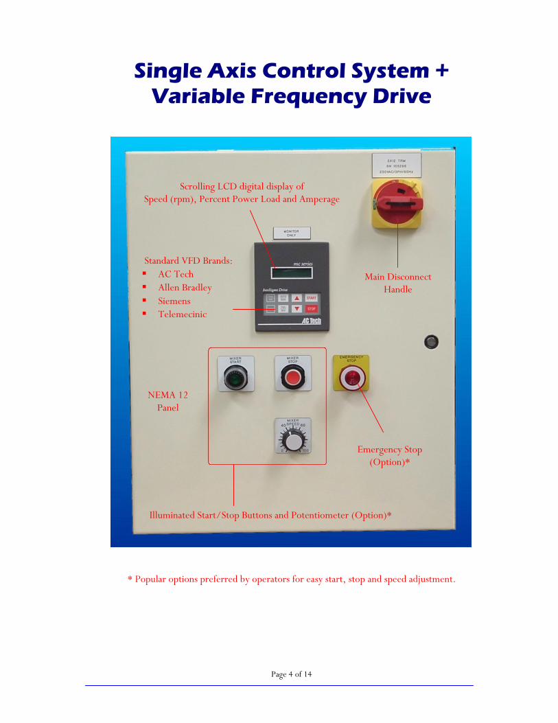
Single Axis Control System + Variable Frequency Drive
* Popular options preferred by operators for easy start, stop and speed adjustment.
Illuminated Start/Stop Buttons and Potentiometer (Option)*
Scrolling LCD digital display of Speed (rpm), Percent Power Load and Amperage
Emergency Stop (Option)*
Standard VFD Brands: � AC Tech � Allen Bradley � Siemens � Telemecinic
Main Disconnect Handle
NEMA 12 Panel

Page 5 of 14
Dual Axis Control System + Variable Frequency Drives
Potentiometers Emergency Stop
Vacuum Start and Stop
Buttons
Individual Start and Stop Buttons for each agitator
Cycle Time Display
Temperature Display Vacuum Level Display
Cycle Time
Start and Stop
Buttons
Speed Displays
Main Disconnect Handle
NEMA 12 Panel

Page 6 of 14
Triple Axis Control System + Variable Frequency Drives
Stainless steel, washdown NEMA 4X Panel
Fan Shrouds for Cooling
Control Transformer
Main Disconnect
Safety Relay Variable Frequency Drives
Enclosure Cooling Fan and Filter
VFD’s and safety circuits are pre-wired to terminal strip for easy field wiring.
Fuse Protection
Page 7 of 14
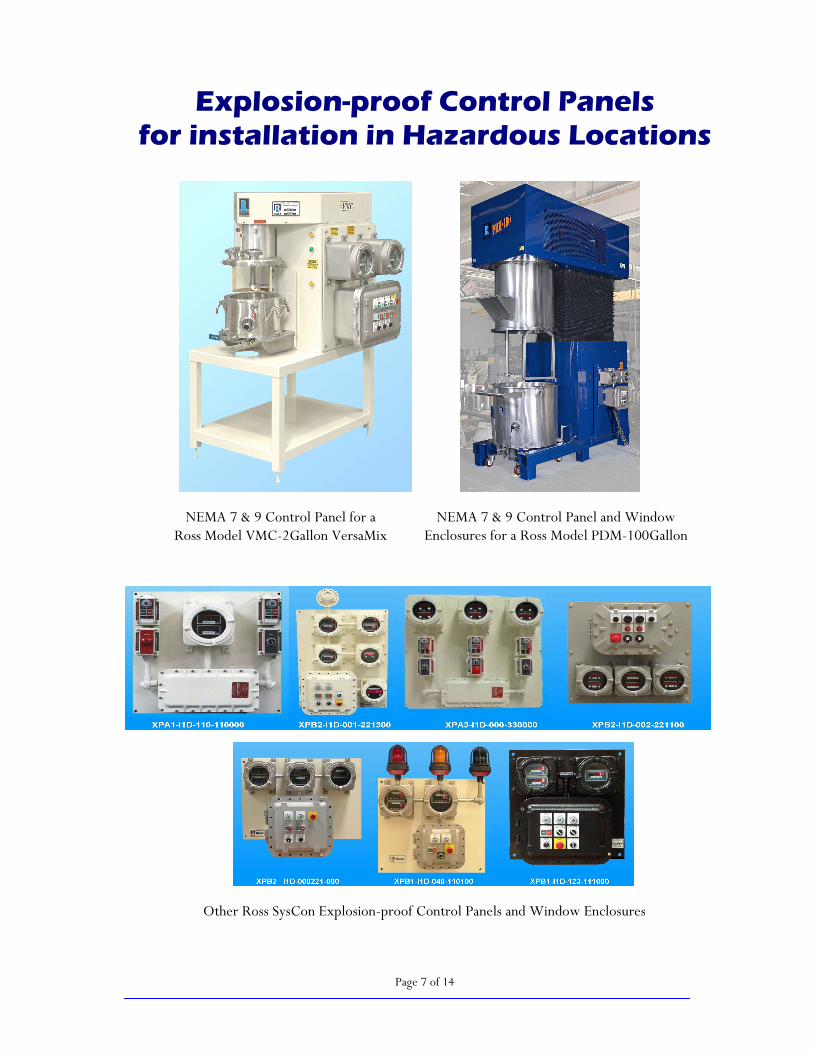
Explosion-proof Control Panels for installation in Hazardous Locations
NEMA 7 & 9 Control Panel for a Ross Model VMC-2Gallon VersaMix
NEMA 7 & 9 Control Panel and Window Enclosures for a Ross Model PDM-100Gallon
PowerMix VersaMix
Other Ross SysCon Explosion-proof Control Panels and Window Enclosures

Page 8 of 14
Sanitary All-Stainless Steel Control Panels (NEMA 4X)
Ross Sanitary Model PDM-1/2Gallon PowerMix
Ross Sanitary Model 5-cu.ft. Tumble Blender with Ross SysCon Touch Screen Controls
Ross Sanitary Model DPM-2Gallon Double Planetary Mixer with HV Blades
Ross Sanitary Bench and Floor Models HSM-400SC2 Inline High Shear Mixers with Solids/Liquid Injection Manifold (SLIM) System. Shown here with VFD’s installed in stainless steel enclosures.
Page 9 of 14
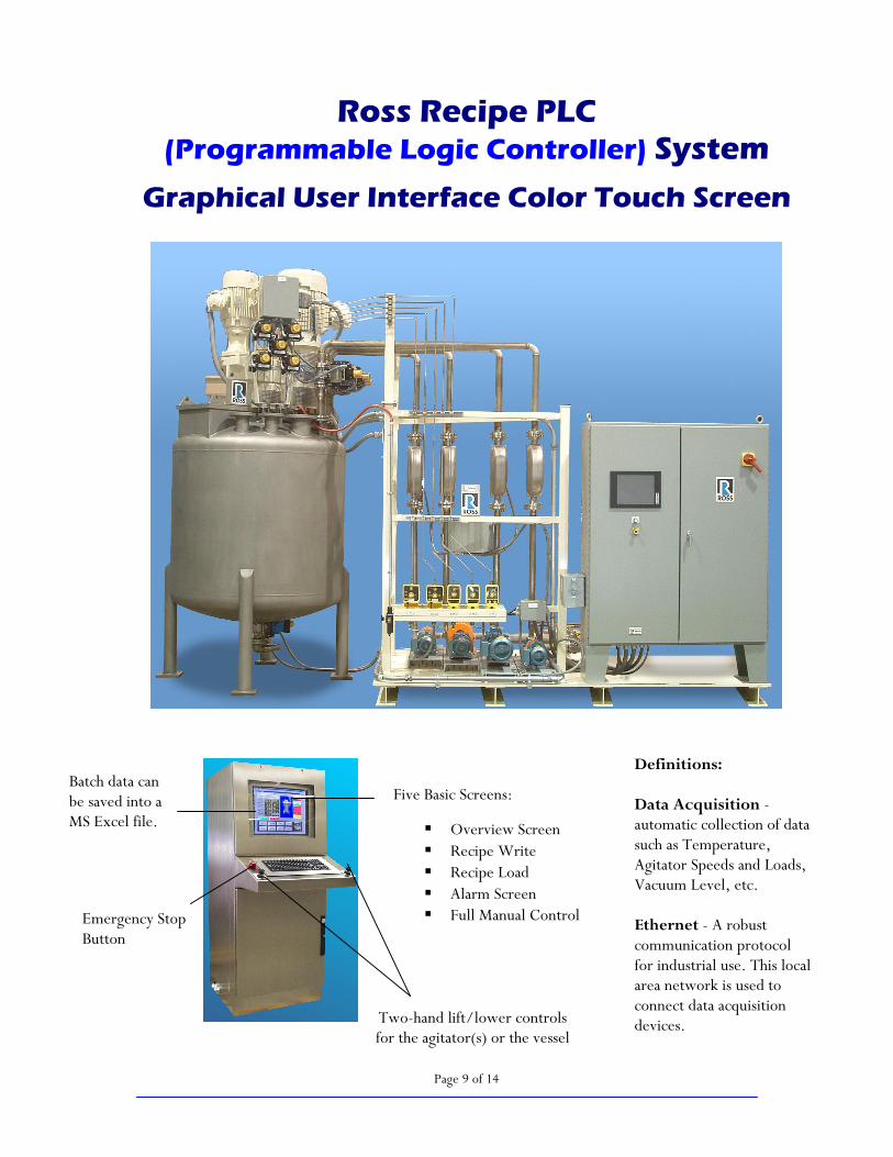
Ross Recipe PLC (Programmable Logic Controller) System
Graphical User Interface Color Touch Screen
Five Basic Screens:
� Overview Screen � Recipe Write � Recipe Load � Alarm Screen � Full Manual Control
Two-hand lift/lower controls for the agitator(s) or the vessel
Emergency Stop Button
Definitions: Data Acquisition - automatic collection of data such as Temperature, Agitator Speeds and Loads, Vacuum Level, etc. Ethernet - A robust communication protocol for industrial use. This local area network is used to connect data acquisition devices.
Batch data can be saved into a MS Excel file.

Page 10 of 14
OVERVIEW SCREEN
6
7
8
9
11
1
4
3
2
5 10
1) RECIPE NUMBER: Displays Recipe Number (1-10) to be executed.
2) STEP NUMBER: Displays the current step of the recipe.
3) CYCLE TIME: Displays the cycle time of each step.
4) MIXER RUNNING INDICATOR: Indicated the running state of the mixer drive.
5) OVERVIEW FIELDS: Displays the setpoints and actual values for each step.
6) CONTROL STATUS INDICATOR: Displays the current control mode of the mixer - Manual or Auto.
7) CYCLE STATUS INDICATOR: Displays the status of the cycle - Running, Stopped or Complete.
8) CYCLE START: Starts the cycle when highlighted and ENTER is depressed.
9) CYCLE STOP: Stops the cycle when highlighted and ENTER is depressed.
Cycle can be restarted at the same point it was stopped.
10) CYCLE RESET: Resets the cycle only after cycle has been completed. To reset cycle
before cycle is completed, a reload of the recipe is required.
11) MAIN SCREEN: Advances operator to the main screen.

Page 11 of 14
RECIPE WRITE SCREEN
2
1
3
4
5
6
1) RECIPE NUMBER: Enter Number (1-10) to identify recipe.
2) STEP FIELDS: Enter setpoints for each step corresponding to MIXER SPEED, HEATING
UNIT TEMPERATURE, VACUUM LEVEL and TIME.
3) WRITE RECIPE: Writes recipe values to PLC memory based on Recipe Number.
4) RECALL RECIPE: Loads recipe values previously written based on Recipe Number.
5) REC LOAD PAGE: Advances operator to the Recipe Load page.
6) MAIN PAGE: Advances operator to the main page.
Page 12 of 14
RECIPE LOAD SCREEN
2
3
1
4
5
6
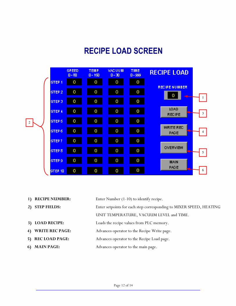
1) RECIPE NUMBER: Enter Number (1-10) to identify recipe.
2) STEP FIELDS: Enter setpoints for each step corresponding to MIXER SPEED, HEATING
UNIT TEMPERATURE, VACUUM LEVEL and TIME.
3) LOAD RECIPE: Loads the recipe values from PLC memory.
4) WRITE REC PAGE: Advances operator to the Recipe Write page.
5) REC LOAD PAGE: Advances operator to the Recipe Load page.
6) MAIN PAGE: Advances operator to the main page.
Page 13 of 14
ALARM SCREEN
1
2
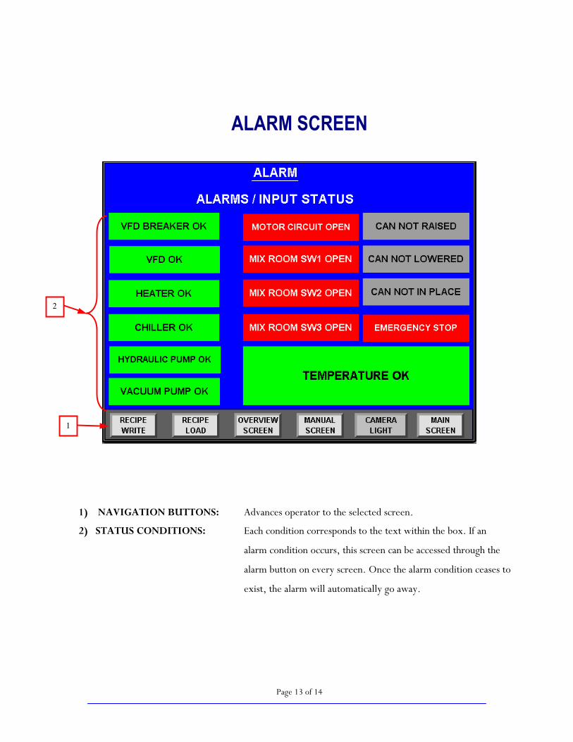
1) NAVIGATION BUTTONS: Advances operator to the selected screen.
2) STATUS CONDITIONS: Each condition corresponds to the text within the box. If an
alarm condition occurs, this screen can be accessed through the
alarm button on every screen. Once the alarm condition ceases to
exist, the alarm will automatically go away.
Page 14 of 14
MANUAL SCREEN
DDS32810C
2
1
3
4
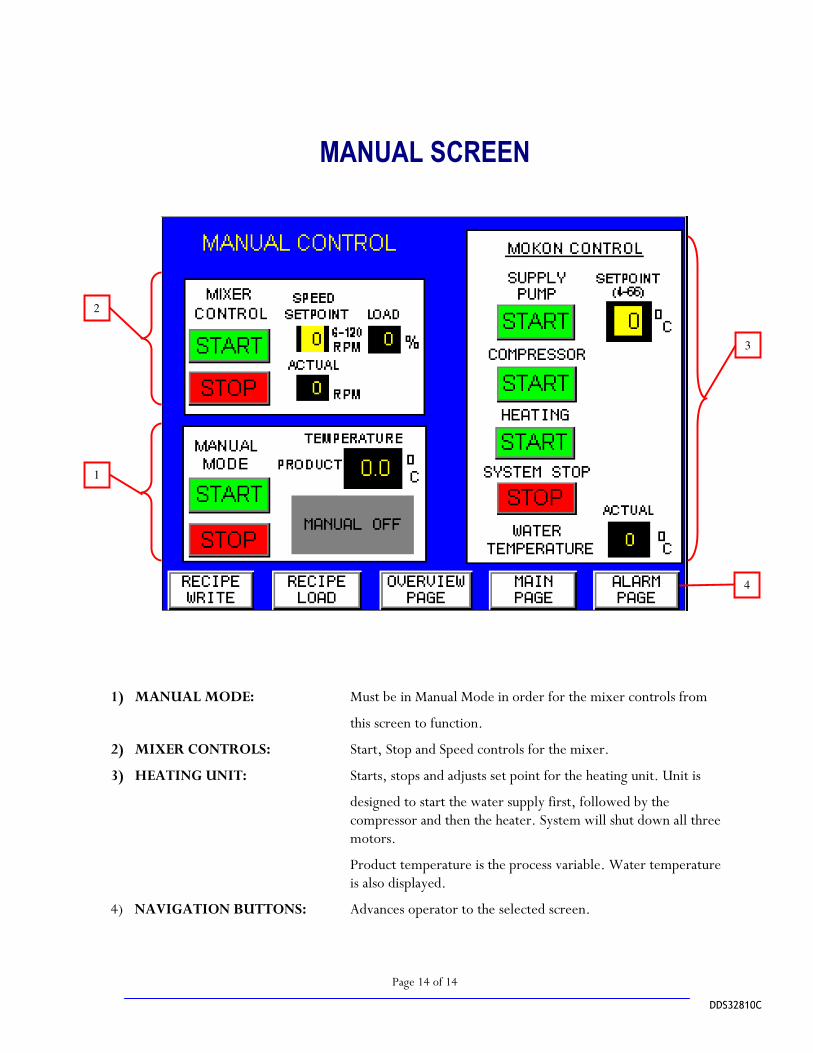
1) MANUAL MODE: Must be in Manual Mode in order for the mixer controls from
this screen to function.
2) MIXER CONTROLS: Start, Stop and Speed controls for the mixer.
3) HEATING UNIT: Starts, stops and adjusts set point for the heating unit. Unit is
designed to start the water supply first, followed by the compressor and then the heater. System will shut down all three motors.
Product temperature is the process variable. Water temperature is also displayed.
4) NAVIGATION BUTTONS: Advances operator to the selected screen.