rosnaini binti saidan - university of malayastudentsrepo.um.edu.my/8352/4/rosnaini_saidan.pdfaliran...
TRANSCRIPT

HIGH TEMPERATURE FORMING OF BORONIZED DUPLEX
STAINLESS STEEL
ROSNAINI BINTI SAIDAN
FACULTY OF ENGINEERING
UNIVERSITY OF MALAYA
KUALA LUMPUR
2015

HIGH TEMPERATURE FORMING OF BORONIZED DUPLEX
STAINLESS STEEL
ROSNAINI BINTI SAIDAN
DISSERTATION SUBMITTED IN FULFILLMENT OF
THE REQUIREMENTS FOR THE DEGREE OF
MASTER OF ENGINEERING SCIENCE
FACULTY OF ENGINEERING
UNIVERSITY OF MALAYA
KUALA LUMPUR
JANUARI 2015
UNIVERSITY OF MALAYA ORIGINAL LITERARY WORK DECLARATION
Name of Candidate: ROSNAINI BINTI SAIDAN I.C. No.: Matric No.: KGA100045
Name of Degree: MASTER OF ENGINEERING SCIENCE
Title of Dissertation (“this Work”): HIGH TEMPERATURE FORMING OF BORONIZED DUPLEX STAINLESS STEEL
Field of Study: ADVANCED MATERIALS
I do solemnly and sincerely declare that:
(1) I am the sole author/write of this Work; (2) This Work is original; (3) Any use of any work in which copyright exists was done by way of fair dealing and
for permitted purposes and any excerpt or extract from, of reference to or reproduction of any copyright work has been disclosed expressly and sufficiently and the title of the Work and its authorship have been acknowledged in this Work;
(4) I do not have any actual knowledge nor ought I reasonably to know that the making of this work constitutes an infringement of any copyright work;
(5) I hereby assign all and every rights in the copyright to this Work to the University of Malaya (“UM”), who henceforth shall be owner of the copyright in this work prohibited without the written consent of UM having been first had and obtained;
(6) I am fully aware that if in the course of making this Work I have infringed any copyright whether intentionally or otherwise, I may be subject to legal action or any other action as may be determined by UM.
Candidate’s Signature Date
Subscribed and solemnly declared before,
Witness’s Signature Date
Name:
Designation:
ii
ABSTRACT
The purpose of this work is to study the forming effect of boronized duplex stainless
steel (DSS) at high temperature. Pack-boronizing of treated-DSS was carried out at 1223
K for 2, 4 and 6 hours, resulting surface hardness that range between 1890 and 2418 HV.
The effects of microstructure, strain rate and surface hardness on high temperature forming
process of the boronized treated-DSS were investigated. The forming was also done to its
counterpart, the untreated (as-received) DSS, as a controlling factor. The results showed
that in general, boronizing increased the flow stress of the forming, as similarly, higher
surface hardness also increased the flow stress of the forming. However, the flow stress of
the boronized treated-DSS was significantly lower than that of the boronized as-received
DSS and comparable to the flow stress of non-boronized as-received DSS, therefore the
flow stress during the forming is not only affected by the surface hardness but also strongly
affected by the original microstructure of the substrate. The much lower flow stress is
attributed to the superplasticity brought about by the fine grain microstructure of the
treated-DSS. The study also concluded that with slower strain rate, the surface integration
of the boronized treated-DSS can be maintained even though the hardness of the boronized
treated DSS is relatively high.

iii
ABSTRAK
Tujuan penyelidikan ini dijalankan adalah untuk mengkaji kesan ubah-bentuk pada
suhu tinggi bagi keluli tahan karat dupleks (DSS) yang diboronkan. DSS terawat
diboronkan pada suhu 1223 K bagi tempoh 2, 4 dan 6 jam, yang menghasilkan kekerasan
permukaan di antara 1890 HV dan 2418 HV. Kesan mikrostruktur, kadar terikan dan
kekerasan permukaan bagi proses ubah-bentuk DSS terawat pada suhu tinggi dikaji.
Ubah-bentuk DSS asal yang diboronkan juga dilakukan untuk tujuan perbandingan. Hasil
kajian menunjukkan secara amnya, pemboronan akan meningkatkan aliran tegasan dalam
proses ubah-bentuk. Kekerasan permukaan yang tinggi juga meningkatkan aliran tegasan
dalam proses ubah-bentuk. Walaubagaimanapun, aliran tegasan bagi DSS terawat yang
diboronkan jelas lebih rendah daripada DSS asal yang diboronkan dan hampir menyamai
aliran tegasan DSS asal yang walaupun tidak diboronkan. Ini bermakna, aliran tegasan
semasa proses ubah-bentuk bukan hanya kesan daripada kekerasan permukaan tetapi jelas
juga disebabkan oleh mikrostruktur bahan tersebut. Tegasan aliran yang rendah ini
disebabkan oleh kesuperplastikan yang daripada butir mikrostruktur halus bagi DSS terawat.
Kajian ini juga merumuskan dengan merendahkan kadar terikan, keteguhan permukaan
bagi DSS terawat yang diboronkan dapat dikekalkan walaupun kekerasannya tinggi.

iv
ACKNOWLEDGEMENTS
Thank you to Allah s.w.t. for giving me the strength and patience to complete my
masters study.
I would like to express my gratitude to Dr. Iswadi Jauhari for an opportunity given
to me to involve in this research. His supervision, advice and guidance as well as the
extraordinary experiences throughout the work are really appreciated. His truly scientist
intuition, oasis of ideas and passions in science, exceptionally inspired and enrich my
growth as a student and enhance my potential in many areas.
A special thanks to my parents, Saidan Bin Nik and Rubiayah Bt Md Yusof for their
love, encouragement and moral support. To my siblings, thanks for being supportive and
caring.
I also like to thank everybody especially my friends; my superplastic team
(Superplastic Girls), Gojus Q, department staffs, and GGG Girls who are important to the
realization of my masters degree.
Last but not least, thank you to Mr. Sharuzzamal, Mr. Firdaus, Farah and PTSBees
family for their understanding and courage on my study. As well as expressing my apology
that I could not mention personally one by one.
Finally, thank you to HIR (UM.C/625/1/HIR/058) and UM (PV053/2011A) for
financing my research project. Apart than that, thank you to the UM RA scheme for
supporting my fees. I am grateful in every possible way.
Rosnaini Binti Saidan Faculty of Engineering, UM 2015

v
TABLE OF CONTENTS
ABSTRACT ii
ABSTRAK iii
ACKNOWLEDGEMENT iv
TABLE OF CONTENTS v
LIST OF FIGURES viii
LIST OF TABLES xi
LIST OF SYMBOLS AND ABBREVIATIONS xii
CHAPTER 1: INTRODUCTION
1.1 General 1
1.2 Research Objectives 2
1.3 Scope of Research
1.3.1 Boronizing Process 3
1.3.2 Forming Process 3
CHAPTER 2: LITERATURE REVIEW
2.1 Superplastcity 4
2.1.1 High Strain Rate Sensitivity 5
2.1.2 Fine Grain size 6
2.1.3 Temperature 7
2.1.4 Mechanism of superplasticity 7
2.1.5 Applications of superplasticity 10

vi
2.2 Boronizing 12
2.3 Duplex Stainless Steel 14
CHAPTER 3: EXPERIMENTAL PROCEDURE
3.1 Substrate Material 18
3.2 Material Preparation 19
3.2.1 Grinding and Polishing 19
3.2.2 Microstructure Evaluation 20
3.3 Fabrication of Jigs and Dies 20
3.3.1 Container for Boronizing Process 20
3.3.2 Jigs and Dies for Forming Process 22
3.4 Boronizing Process 23
3.5 Forming Process 24
3.6 Characterization Methods 26
3.6.1 X-ray Diffraction Analysis (XRD) 27
3.6.2 Optical Microscopy (OM) 27
3.6.3 Scanning Electron Microscopy (SEM)
28
3.6.4 Microhardness Tester 30
vii
CHAPTER 4: RESULTS AND DISCUSSIONS
4.1 Substrate Material 32
4.2.1 X-ray Diffraction Analysis 33
4.2.2 Boronized Layer Characterization 34
4.3 Forming Process 39
4.3.1 Microstructure Effect on Flow Stress 40
4.3.2 Surface Hardness Effect on Flow Stress 42
4.3.2.1 Near-Surface Microstructure: Effect of Surface Hardness and Grain Microstructure 43
4.3.3.1 High Strain Rate Sensitivity (m value) 45
4.3.3.2 Near-surface Microstructure: Effect of Strain Rate 47
CHAPTER 5: CONCLUSIONS
5.1 Conclusions 49
5.2 Recommendations 50
REFERENCES 51
PUBLICATIONS 55

viii

ix
LIST OF FIGURES
Figure Captions Page
2.1 A demonstration of superplasticity in Cu–Al alloy (8000% elongation) 4
2.2 Normalized curve of log stress versus log strain 6
2.3 Effect of decreasing grain size on the range of superplastic region
6
2.4 Evolution of microstructure during superplastic deformation (Chandra, 2002)
8
2.5 The process of diffusional accommodation (Zelin and Mukherjee,1996) 9
2.6 (a) the core inside the grain and mantle at the grain boundary (b) dislocation motion inside the mantle results in the grain rotation (D = diameter).(Zelin and Mukherjee, 1996)
9
2.7 The accommodation which combines dislocation and diffusional processes
10
2.8 (a) Superplastic forming (SPF) process. (Internet Source-1) (b) Superplastic forming of a superalloy gas-turbine rotor with integral blades (Internet Source-2)
11
2.9 Near equal amount of austenite (light etched regions) and ferrite (dark etched regions) microstructure of duplex stainless steel (Muthupandi et al, 2005).
15
2.10 Fe-Cr-Ni phase diagram (Internet Source-3) 15
2.11 Microstructure of fine grain duplex stainless steel (Miyamoto et al., 2001)
16
3.1 Flow of thermo-mechanical treatment process of DSS 19
3.2 Dimension of the cutting specimen of DSS 19
3.3 Schematic diagram of conventional boronizing container 21
3.4 Fabricated conventional boronizing container 21

x
3.5 Drawing dimension of lower and upper jigs that used for deformation proces (a) Drawing dimension of upper jig (b) Drawing dimension lower jig
22
xi
3.6 Dimension of dies from (a) top and (b) side views 23
3.7 Schematic diagram of pack-boronizing set up inside the conventional boronizing container
23
3.8 Flow diagram of boronizing process
24
3.9 Picture of Instron compression machine (a) and schematic diagram of experimental apparatus (b) for forming process
25
3.10 X-Ray Diffraction analysis machine 27
3.11 Optical microscope model Zeiss Axiotech with connected digital camera and image analyzer
28
3.12 Scanning electron microscope (SEM) 29
3.13 Microscope chamber of the SEM where the samples are placed for analysis
30
3.14 Mitutuyo microhardness tester model MVK-H2 31
4.1 Optical microscope images of (a) thermo-mechanically treated and (b) as-received DSS
32
4.2 X-ray diffraction pattern of as-received and treated-DSSs before and after boronizing at 1223K for 6 hours
34
4.3 Cross-section of all boronized DSS at 1223 K for 6 hours 35
4.4 Boronized layer thicknesses for different boronizing time and type of microstructure
36
4.5 Graph of boronized layer thicknesses for different boronizing times and types of microstructure
37
4.6 Microhardness of cross-sectional DSS, boronized at 1223 K for different hours and different types of microstructure
38
4.7 Microhardness gradient profile of all boronized samples; A (Treated-2hr), B (Treated-4hr), C (Treated-6hr) and D (As-received-6hr)
39
4.8 Stress-strain relationship of forming boronized samples; C (Treated-6hr) and D (As-received-6hr) and un-boronized samples; H (Treated-6hrs-Unboron) and I (As-received-DSS-6hrs-Unboron)
41
xii
4.9 Flow stress of forming at temperature of 1223 K for boronized treated-DSS; Sample A (Treated-2hr), Sample B (Treated-4hr) and Sample C (Treated-6hr)
43
4.10 Cross-sectional images of deformed boronized treated DSS and boronized as-received at strain rate of 1×10⁻⁴ s-1 for strain 0.4 at temperature 1223 K
44
4.11 Strain rate sensitivity (m) for superplastic forming at different strain rate; 1x10⁻⁴ s-1 (Sample C), 1×10⁻³ s-1 (Sample E), 2×10⁻⁴ s-1 (Sample F), and 6×10⁻⁵ s-1 (Sample G)
46
4.12 Stress-strain relationship for boronized treated DSS deformed at 1x10⁻⁴ s-1 (Sample C), 1×10⁻³ s-1 (Sample E), 2×10⁻⁴ s-1 (Sample F), and 6×10⁻⁵ s-1 (Sample G)
47
4.13
FESEM images of boronized treated-DSS deformed at 1223 K for different strain rate; 1×10⁻³ s-1 (Sample E), 2×10⁻⁴ s-1 (Sample F) and 6×10⁻⁵ s-1 (Sample G) and strain of 0.4
48

xiii
LIST OF TABLES
Table Caption Page
3.1 Chemical composition of duplex stainless steel (JIS SUS329J1) in wt %
18
3.2 Summary of experimental conditions for deformation process 26
4.1 Characterization of as-received and treated DSSs 33
4.2 Boronized layer thickness of treated and as-received DSSs at different times
36
4.3 Forming process conditions of boronized and un-boronized samples for treated and as-received DSSs
40
4.4 Forming process at strain rate 1x10⁻⁴ s-1 and strain of 0.4 of treated DSS boronized for different time
42
4.5 Superplastic forming of treated DSS boronized for 6 hours at different strain rate
45

xiv
LIST OF SYMBOLS AND ABBREVIATIONS
Symbols Explanation
m Strain-rate sensitivity
σ Plastic flow stress
F Applied force
A Cross-sectional area
K Constant
xv
Abbreviations Explanation
DSS Duplex Stainless Steel
SEM Scanning Electron Machine
FESEM Field Emission Scanning Electron Microscope
EDM Electrical Discharge Machine
XRD X-ray Diffraction
JIS
GBS
Japanese Industrial Standards
Grain Boundary Sliding
Tm Melting Temperature
m High Strain-Rate Sensitivity
FeB Ferum Boride
Fe2B Ferum (II) Boride
CrB Chromium Boride

1
CHAPTER 1
INTRODUCTION
1.1 General
Superplasticity is the phenomenon where a material undergoes a very large plastic
deformation before failure. Superplastic materials are characterized by their exceptional
ductility where an elongation as high as 8000% can be achieved (Carrino et al., 2003).
Since this phenomenon offers a lot of industrial potentials, numerous attempts have been
made to develop superplasticity in various materials and also to apply the technology in
engineering areas.
Boronizing is one of the surface engineering techniques used to harden surface of
steel. Boronizing is a thermochemical treatment in which boron atoms are diffused into a
metal surface to form hard boride layers with the base material. It was reported that a wide
range of materials including ferrous materials, non-ferrous materials and some super alloys
can be boronized (Vipin Jain, G. Sundararajan, 2002). The boronizing process can be
carried out in solid, liquid or gaseous medium. The most frequently used method is in solid
medium or pack boronizing, because of the simplicity of equipment.
Previous studies show that combination of superplasticity phenomenon and
boronizing has successfully improved the properties of duplex stainless steel. The results
obtained through dual compression method also initiated a new development of high
temperature forming through this work (I. Jauhari et. al, 2011).
In this study, duplex stainless steel (DSS) is used as the boronized substrate material.
Besides characterized by the balance ratio of α-ferrite and γ-austenite, DSS is a material

2
that can exhibit superplastic behaviour at high temperature. DSS is widely utilized in oil
and gas production and transmission, petroleum industries, petro-chemical process plants,
shipbuilding, transportations and for pulp and paper production equipments (F. Zucchi et. al,
2005 and H. Sieurin, R. Sandstrom, 2005).
Conventionally, devices or parts are initially formed to a specific shape before the
boronizing process and not to be exposed to any plastic deformation process after
boronizing to avoid surface disintegration. However, for complex-shaped parts, it is
difficult to attain a uniform boronizing. Contrary to this conventional process, this research
develops deformation process to form parts or devices after boronizing bulk material.
First step of the process is boronizing of duplex stainless steel to achieve a certain
degree of hardness and uniform boronized layer. The second step is hot deformation on the
boronized DSS at different parameters; surface hardness, type of microstructure and strain
rate. Un-boronized DSS was also deformed for comparison purpose.
1.2 Research Objectives
The objectives of this research are:
a) To study the feasibility of superplastic deformation of boronized duplex
stainless steel
b) To evaluate properties of forming boronized duplex stainless steel

3
1.3 Scope of Research
There are two parts in this work which are explained in the next subsections.
1.3.1 Boronizing Process
Pack-boronizing was conducted using a stainless steel container at different
boronizing time. Two different types of microstructure; fine and coarse grains were used for
comparison purpose. The process was carried out in a tube furnace with controlled
atmosphere using argon gas at superplastic temperature. Boronized layer thickness and
surface hardness before and after boronizing were evaluated.
1.3.2 Forming Process
Boronized DSS from process in subsection 1.3.1 was used. Forming process at high
temperature was performed using compression testing machine that equipped with
high-temperature furnace under controlled gas atmosphere. Boronized DSS was deformed
without presence of boron powder at different strain rate. Effects of grain microstructure,
surface hardness and strain rate were analyzed.

4
CHAPTER 2
LITERATURE REVIEW
2.1 Superplasticity
In general, superplasticty can be defined as a phenomenon of materials that are able
to undergo large uniform strains prior to failure in excess of 200% or more. The current
record for elongation in metals which stands at 8000% elongation in commercial bronze is
shown in Figure 2.1 (Chandra, 2002). Superplasticity has been observed in several kinds of
materials, such as metals (including aluminium, magnesium, iron, titanium and
nickel-based alloys), ceramics (including monolitihcs and composites), intermetallics
(including iron, nickel, titanium base) and laminates (Xing et. al., 2004). There are 2 types
of superplasticity which are micrograin or structural superplasticity and internal stress
superplasticity (Valiev, 2000).
Figure 2.1 A demonstration of superplasticity in Cu–Al alloy (8000% elongation)
It has been reported that superplastic behavior in most metals, alloys and ceramics
are associated with three main characteristic stated by Hertzberg (1996)
(1) fine grain size (on the order of 1-10μm)
(2) deformation temperature > 0.5 Tm (where Tm is the absolute melting point)
(3) a strain rate sensitivity factor m which is more than 0.3

5
2.1.1 High Strain Rate Sensitivity
Strain rate sensitivity represents the capacity of the material to resist necking and
influences the overall deformation during superplastic deformation (Kirthi, 2007). High
strain rate sensitivity allows inhibition of necking, which means no localized of failure at a
reduced-cross section area. For superplastic alloys, the characteristic mechanical behavior
observed is a strong dependence of flow stress, σ on strain rate,ε at the superplastic
temperature. The strain rate sensitivity exponent referred to as m provides a measure of the
strain rate sensitivity of flow stress and can be defined by the equation below:
m = ∂ (ln σ) ∂ ( ln ε ) (1) It follows that, from expressing the flow stress-strain rate relation by the following equation:
mK
AF εσ == (2)
where F = applied force A = cross-sectional area K = constant
dtdA
Aldtdl 11
−==ε = strain-rate
m = strain-rate sensitivity factor
Superplastic behavior is usually observed when m is greater or equal to 0.4. For
most superplastic materials m lies within the range of 0.4 to 0.8. Figure 2.2 shows the
relation between σ, ε and m.

6
Figure 2.2 Normalized curve of log stress versus log strain
2.1.2 Fine grain size
As mentioned earlier, fine grain size is one of the main characteristic of
superplasticity. It has been well understood that ductility of materials increases as the grain
size becomes finer. It is critical for the material to have fine grain structure in order to
create superplasticity or to deform in the superplastic condition. Figure 2.3 illustrates that
decreasing grain size has an effect on widening the superplastic region. Metals with fine
grain microstructure sized within the range of 1- 10 µm tends to exhibit superplasticity at
the temperature of deformation.
Figure 2.3 Effect of decreasing grain size on the range of superplastic region

7
2.1.3 Temperature
Temperature is considered to be one of the most important parameters in
superplastic deformation since temperature is closely related with superplastic deformation
and the movement of matter in general. Superplasticity is considered as the movement of
matter such as gas particles, solid particles and water particle. The movement of matter is a
temperature-dependent mechanism.
Superplasticity in most materials commonly occurs at elevated temperature. The
optimal temperature of superplastic forming is higher than 0.5 Tm where Tm is the melting
point of material expressed in Kelvin.
2.1.4 Mechanism of Superplasticity
Several metallurgical factors have been proposed to explain superplastic behavior.
Superplasticity results in high ductility through grain boundary sliding and fine equiaxed
microstructure. Grains are observed to change their neighbours and seen to emerge at the
free surface from the interior (Chandra, 2002). The particular structural condition is that the
material is of very fine grain size and the presence of a two-phase structure is usually of
importance in maintaining this fine grain size during testing. Furthermore, the strain rate of
superplastic deformation depends strongly on the grain size of the materials and
temperature.
Several models of mechanisms have been proposed for superplastic deformation
(Langdon, 1970; Mukherjee, 1971; Gifkins, 1976; Arieli and Mukherjee, 1980). Recent
studies using high voltage transmission electron microscope (TEM) support the idea that
grain boundary sliding is the primary mechanism (Chandra, 2000). Figure 2.4 shows the
microstructure movement during superplastic deformation. In superplastic deformation

8
however, strain in a given direction is due to the motion of individual grains or clusters of
grains relative to each other by sliding and rolling. During deformation, the grains remain
equiaxed or become equiaxed. Although there is some difference in grain shape during the
accommodation, the grain shape and size remain identical before and after deformation.
Figure 2.4 Evolution of microstructure during superplastic deformation (Chandra, 2002)
The accommodation mechanisms can be divided into three general groups
(Mukherjee, 2002): (a) diffusional accommodation, (b) accommodation by dislocation
motion and (c) combined model with elements of dislocation and diffusional
accommodation.
Diffusional accommodation occurs when the mass flow is due to the diffusion
process in the vicinity of grain boundary. When a load is applied to a material, the
deformation is due to grain boundary diffusion and sliding, as a result of strain. The process
is indicated in Figure 2.5.
Initial microstructure
Intermediate microstructure
Final microstructure
9
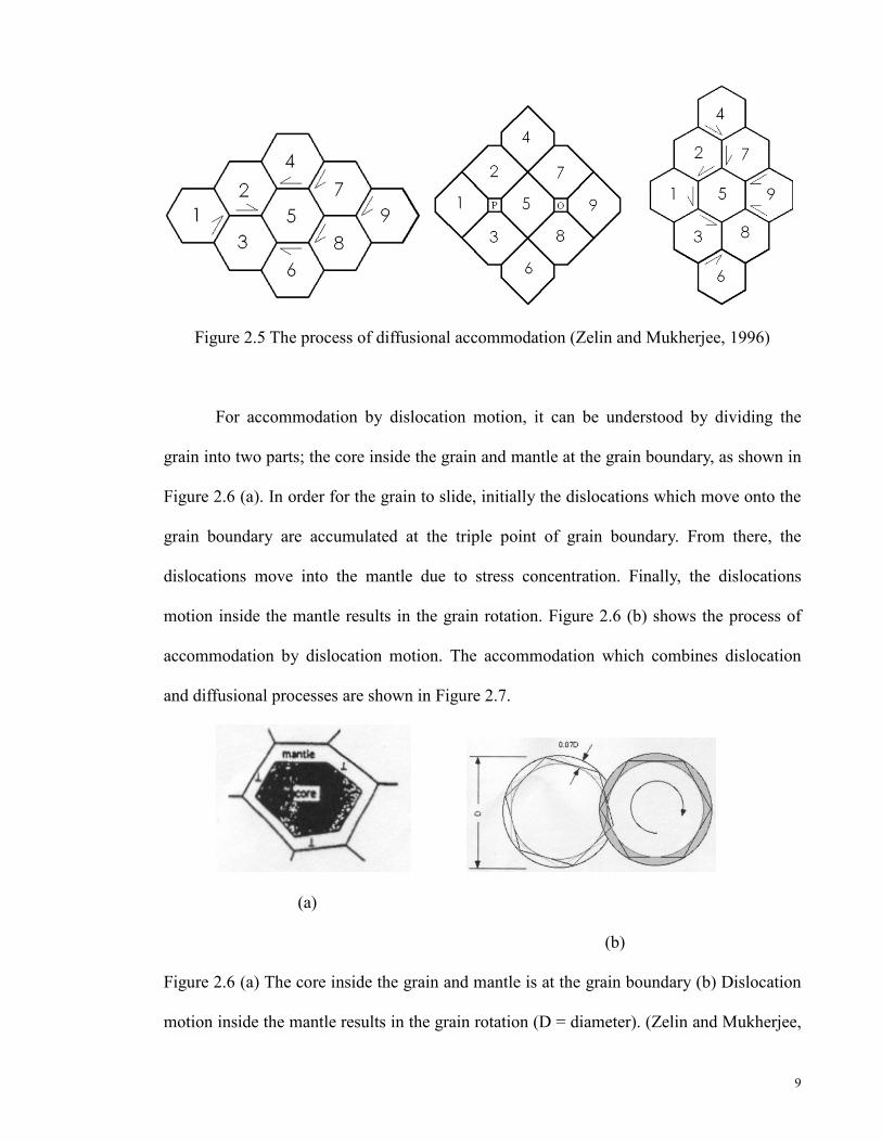
Figure 2.5 The process of diffusional accommodation (Zelin and Mukherjee, 1996)
For accommodation by dislocation motion, it can be understood by dividing the
grain into two parts; the core inside the grain and mantle at the grain boundary, as shown in
Figure 2.6 (a). In order for the grain to slide, initially the dislocations which move onto the
grain boundary are accumulated at the triple point of grain boundary. From there, the
dislocations move into the mantle due to stress concentration. Finally, the dislocations
motion inside the mantle results in the grain rotation. Figure 2.6 (b) shows the process of
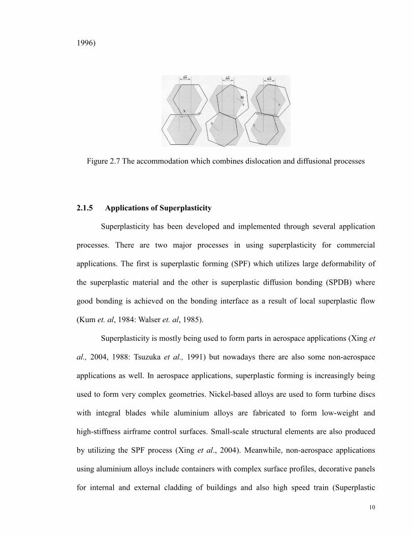
accommodation by dislocation motion. The accommodation which combines dislocation
and diffusional processes are shown in Figure 2.7.
(a)
(b)
Figure 2.6 (a) The core inside the grain and mantle is at the grain boundary (b) Dislocation
motion inside the mantle results in the grain rotation (D = diameter). (Zelin and Mukherjee,
10
1996)
Figure 2.7 The accommodation which combines dislocation and diffusional processes
2.1.5 Applications of Superplasticity
Superplasticity has been developed and implemented through several application
processes. There are two major processes in using superplasticity for commercial
applications. The first is superplastic forming (SPF) which utilizes large deformability of
the superplastic material and the other is superplastic diffusion bonding (SPDB) where
good bonding is achieved on the bonding interface as a result of local superplastic flow
(Kum et. al, 1984: Walser et. al, 1985).
Superplasticity is mostly being used to form parts in aerospace applications (Xing et
al., 2004, 1988: Tsuzuka et al., 1991) but nowadays there are also some non-aerospace
applications as well. In aerospace applications, superplastic forming is increasingly being
used to form very complex geometries. Nickel-based alloys are used to form turbine discs
with integral blades while aluminium alloys are fabricated to form low-weight and
high-stiffness airframe control surfaces. Small-scale structural elements are also produced
by utilizing the SPF process (Xing et al., 2004). Meanwhile, non-aerospace applications
using aluminium alloys include containers with complex surface profiles, decorative panels
for internal and external cladding of buildings and also high speed train (Superplastic
11
aluminium forming, 1988).
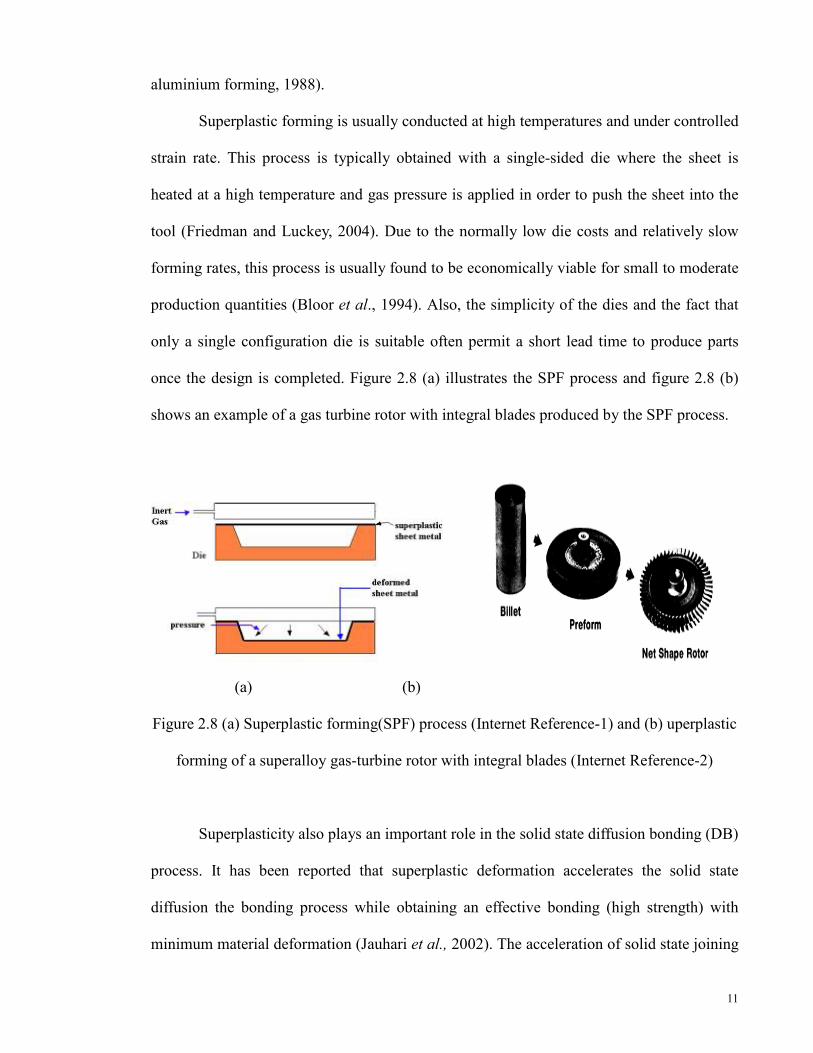
Superplastic forming is usually conducted at high temperatures and under controlled
strain rate. This process is typically obtained with a single-sided die where the sheet is
heated at a high temperature and gas pressure is applied in order to push the sheet into the
tool (Friedman and Luckey, 2004). Due to the normally low die costs and relatively slow
forming rates, this process is usually found to be economically viable for small to moderate
production quantities (Bloor et al., 1994). Also, the simplicity of the dies and the fact that
only a single configuration die is suitable often permit a short lead time to produce parts
once the design is completed. Figure 2.8 (a) illustrates the SPF process and figure 2.8 (b)
shows an example of a gas turbine rotor with integral blades produced by the SPF process.
(a) (b)
Figure 2.8 (a) Superplastic forming(SPF) process (Internet Reference-1) and (b) uperplastic
forming of a superalloy gas-turbine rotor with integral blades (Internet Reference-2)
Superplasticity also plays an important role in the solid state diffusion bonding (DB)
process. It has been reported that superplastic deformation accelerates the solid state
diffusion the bonding process while obtaining an effective bonding (high strength) with
minimum material deformation (Jauhari et al., 2002). The acceleration of solid state joining
12
by superplastic deformation is closely related to the development of grain boundary sliding
in the material (Lutfulin et. al., 1995). These processes permit fabrication of parts with
local thickness variations, attachments and complex sandwich structures (Bloor et at.,
1994). SPF together with DB has been implemented to produce hollow engine blades, fan
and compressor blades for aero engines (Xun and Tan, 2000; Xing et. al., 2004).
2.2 Boronizing
Boronizing has been widely used to improve the surface properties of metals.
Nowadays, boronizing is being successfully applied to ferrous and non-ferrous alloys
(Balokhonov et al, 2000; Hoffmann et al,2001). The boride layer produced through
boronizing have high hardness, good wear resistance and high corrosion and oxidation
resistance (C.H. Xu et al, 1997). With hardness produced exceeding 2000 HV, this process
promises a better resistance to friction and abrasion compared to carburizing and nitriding
(Sinha, 1991; Meric et al., 2000).
The boronizing process can be carried out in a solid, liquid or gaseous medium.
Among these methods, boronizing is mostly carried out by the solid or pack-medium
method due to its simplicity and cost-effectiveness (Keddam and Chentouf, 2005). In the
boronizing process, boron is diffused into the surface layer of metal. Boron is usually
derived from a solid, gaseous or liquid substance which is in contact with the metal surface.
Chemical reaction is not involved directly with the metal but may be catalyzed by the
presence of the metal.
As mentioned in a previous section, although liquid and gas boronizing are usually
used nowadays, solid or pack boronizing still remains as a process that is the most simple,
economical, original and industrially reliable.

13
Pack boronizing is a process in which boron is derived from a solid compound that
decomposes at the metal surface. This process consists of packing the work piece in a
container containing a solid boronizing agent (boronizing powder) and heating it slowly in
a furnace to attain a temperature of about 1173 K to 1223 K. To avoid complications,
boronizing should be carried out in a protective gas atmosphere, which may be pure argon,
pure nitrogen or a mixture of hydrogen and either argon or nitrogen.
The containers used for pack boronizing are usually made from heat resistant steels
which is most economical in the long run. To avoid unevenly boronized parts, the use of
smaller containers is generally preferred for a more uniform effect on the boronized
components.
In pack-boronizing, temperature and time are the main control factors. The
thickness of boride layer is determined by the temperature and time of the treatment (Jain
and Sundararajan, 2002). The boron amount determines how much it can be diffused and
the temperature determines the depth of boron penetration for a set of holding time. In
general, the boron atoms diffused lead to formation of a thicker boronized layer. In order to
produce a certain degree of boronizing and boronized thickness layer, it is very crucial to
select the suitable parameters. The easiest way to obtain thicker boronized layer is by
increasing the temperature. However, there is a temperature limitation due to thermal shock
in cooling and it is imperative to maintain the fine microstructure of the work piece.
14
2.3 Duplex Stainless Steel
Duplex Stainless Steel (DSS) contain between 18 to 25% chromium, 4 to 7% nickel
and up to 4% molybdenum and is water quenched from a hot working temperature that is
between 1000 and 1050oC to produce a microstructure that is approximately half ferrite and
half austenite (Kohser et al. , 2003). The nickel content is insufficient to generate a fully
austenitic structure and the result of the combination of ferritic and austenitic structure is
called duplex.
The duplex stainless steel, as its name implies, are defined as a family of stainless
steel which consists of a two phase aggregated microstructure of α-ferrite and γ-austenite.
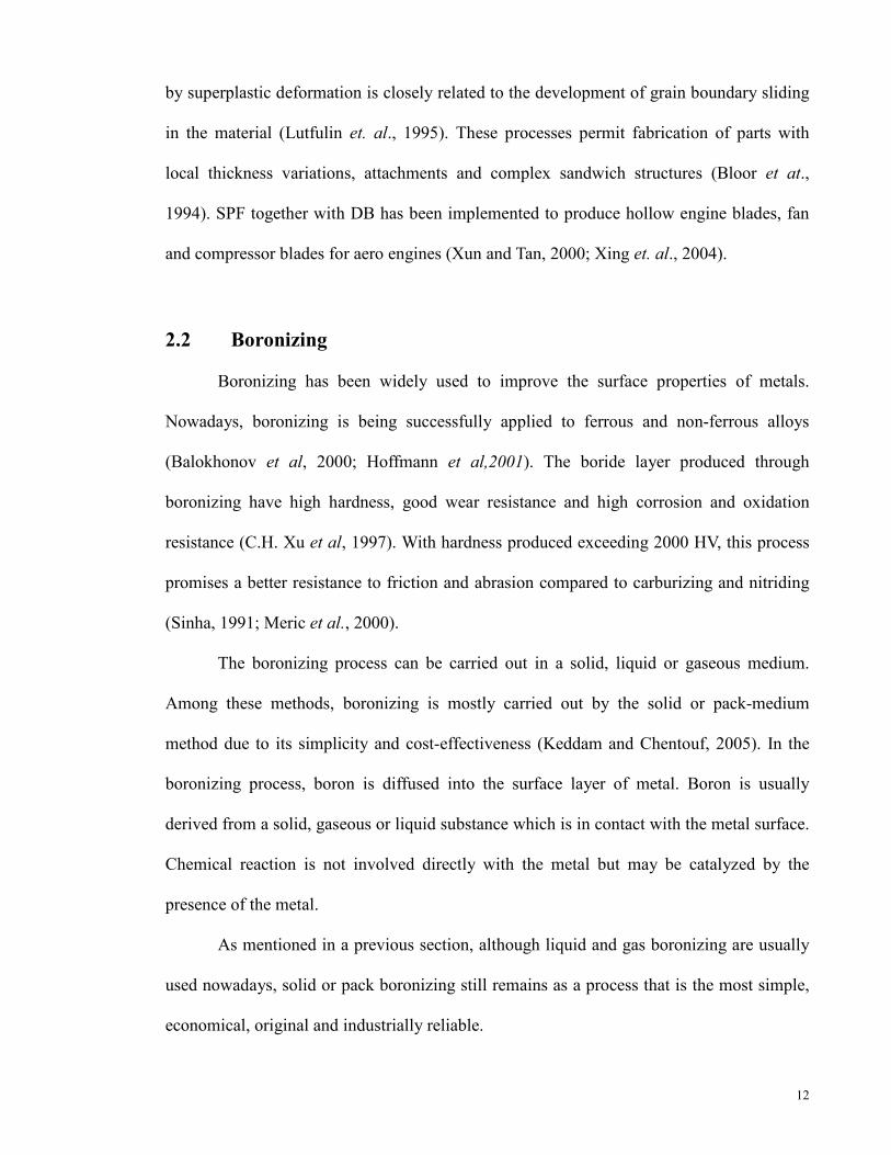
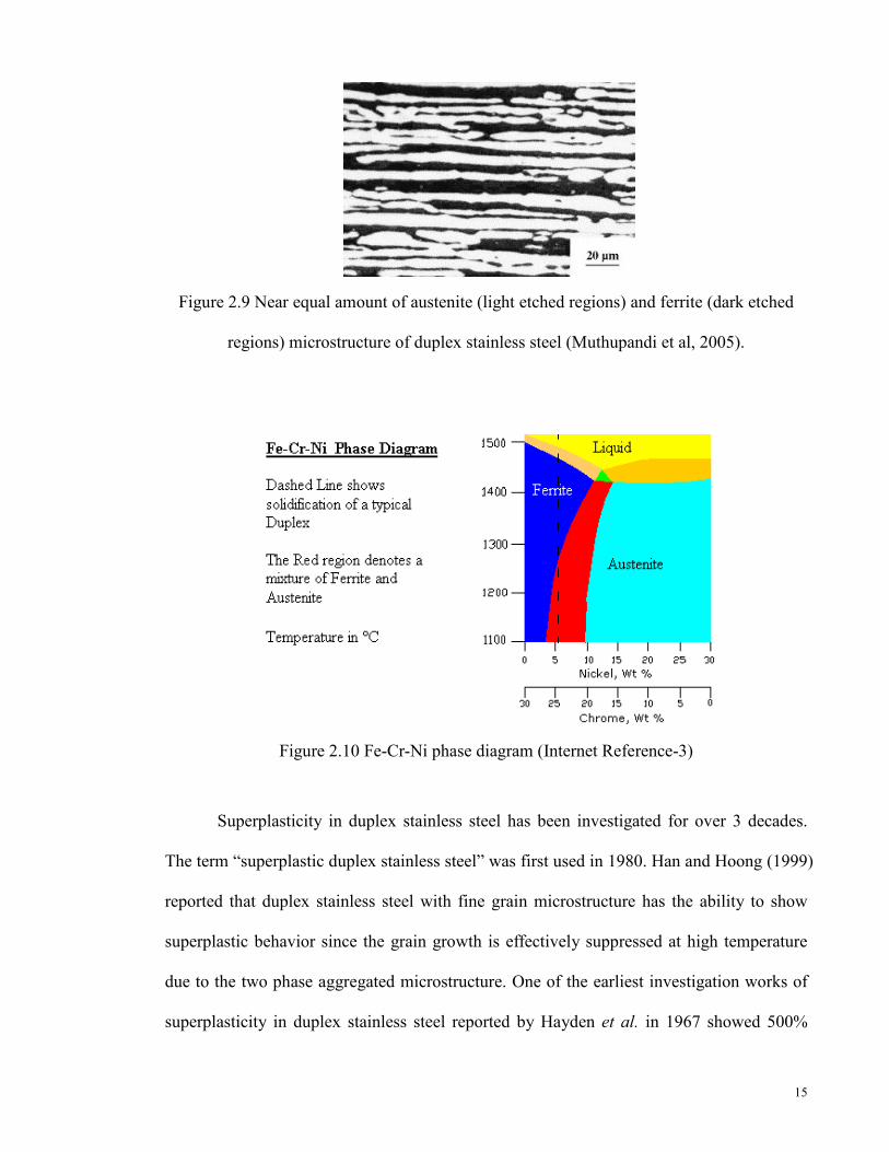
The microstructure of the standard duplex stainless steel that consist both ferritic and
austenitic structures is shown in Figure 2.9. It combines the attractive properties of
austenitic and ferritic stainless steel: high tensile strength and fatigue strength, good
toughness even at low temperatures, adequate formability and weldability and excellent
resistance to stress corrosion cracking, pitting and general corrosion (Cabrera et al., 2003).
These factors promote DSS as an alternative to austenitic stainless steels.
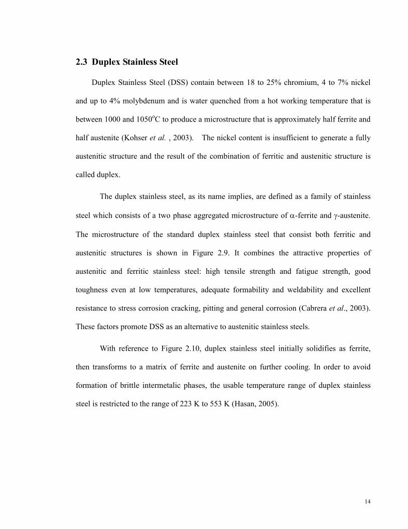
With reference to Figure 2.10, duplex stainless steel initially solidifies as ferrite,
then transforms to a matrix of ferrite and austenite on further cooling. In order to avoid
formation of brittle intermetalic phases, the usable temperature range of duplex stainless
steel is restricted to the range of 223 K to 553 K (Hasan, 2005).
15
Figure 2.9 Near equal amount of austenite (light etched regions) and ferrite (dark etched
regions) microstructure of duplex stainless steel (Muthupandi et al, 2005).
Figure 2.10 Fe-Cr-Ni phase diagram (Internet Reference-3)
Superplasticity in duplex stainless steel has been investigated for over 3 decades.
The term “superplastic duplex stainless steel” was first used in 1980. Han and Hoong (1999)
reported that duplex stainless steel with fine grain microstructure has the ability to show
superplastic behavior since the grain growth is effectively suppressed at high temperature
due to the two phase aggregated microstructure. One of the earliest investigation works of
superplasticity in duplex stainless steel reported by Hayden et al. in 1967 showed 500%

16
elongation in 25Cr-6.5Ni-0.6Ti hot-rolled duplex stainless steels.
Since a fine-grained microstructure is the most important feature of superplastic
materials, it is known that the processing step in producing the finest microstructures which
are stable at the deformation temperature and would enhance superplasticity is definitely
important. Several distinct thermo-mechanical processing techniques have been used to
develop a superplastic microstructure in duplex stainless steels. One example is
thermo-mechanical process which consists of hot-rolling the material in the temperature
range of 1100–1300°C followed by cold-rolling with 50% reduction (Jimenez et al, 2001).
The fine grain duplex microstructure is obtained through precipitation of the second phase
particles when the thermo-mechanically treated duplex stainless steel is heated up at test
temperature (Han and Hong, 1999). Figure 2.11 shows the microstructure of
thermo-mechanically treated duplex stainless steel with grain sizes of about 10 µm after it
has been heated, up at test temperature ranging from 850 to 1100°C.
Figure 2.11 Microstructure of fine grain duplex stainless steel (Miyamoto et al., 2001)

17
It has been reported by Jimenez et al. (2001) that the microstructure evolution
during deformation identifies grain boundary sliding as the mechanism responsible for
superplastic deformation of duplex stainless steels. On the other hand, some previous
studies suggest that the dynamic recrystallization of the softer phase in duplex stainless
steel or other duplex microstructure, which occurs continuously during deformation, could
be the dominant mechanism for superplasticity at temperatures in the range 800–191100°C.
However, Tsuzaki et al. (1996) suggested that grain boundary sliding is the dominant
mechanism for superplasticity in duplex stainless steel, and the role of dynamic
recrystallization is to keep the grain size fine, suitable for grain boundary sliding.
Furthermore, the study conducted by Han and Hong (1999) also concluded that the grain
boundary sliding assisted by dynamic recrystallization is considered to be the controlling
mechanism for superplastic deformation of DSS.
Based on the previous studies on dual compression method by I. Jauhari et. al
(2011), the present work is developed in order to study the feasibility of high temperature
forming behaviour of DSS. The characteristics of superplasticity on duplex stainless steel
are exploited through forming process. Extra attention was given to observations made on
superplastic effect and surface integrity of the substrate during the forming process. The
results gathered therein shall then become the reference for the employment of plastic
deformation process after boronizing or generally after surface hardening processes.
18
CHAPTER 3
EXPERIMENTAL PROCEDURE
3.1 Substrate Material
Duplex stainless steel (DSS) compared to Japanese Industrial Standards (JIS
SUS329J1) was used as the substrate material in this study. The chemical composition of
the DSS is shown in Table 3.1.
Table 3.1 Chemical composition of duplex stainless steel (JIS SUS329J1) in wt %
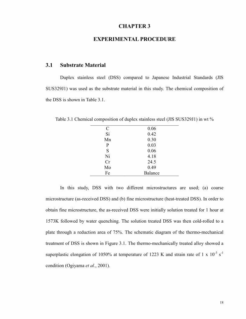
In this study, DSS with two different microstructures are used; (a) coarse
microstructure (as-received DSS) and (b) fine microstructure (heat-treated DSS). In order to
obtain fine microstructure, the as-received DSS were initially solution treated for 1 hour at
1573K followed by water quenching. The solution treated DSS was then cold-rolled to a
plate through a reduction area of 75%. The schematic diagram of the thermo-mechanical
treatment of DSS is shown in Figure 3.1. The thermo-mechanically treated alloy showed a
superplastic elongation of 1050% at temperature of 1223 K and strain rate of 1 x 10⁻³ s-1
condition (Ogiyama et al., 2001).
C Si
Mn P S Ni Cr Mo Fe
0.06 0.42 0.30 0.03 0.06 4.18 24.5 0.49
Balance
19
Figure 3.1 Flow chart of the thermo-mechanical treatment process of DSS
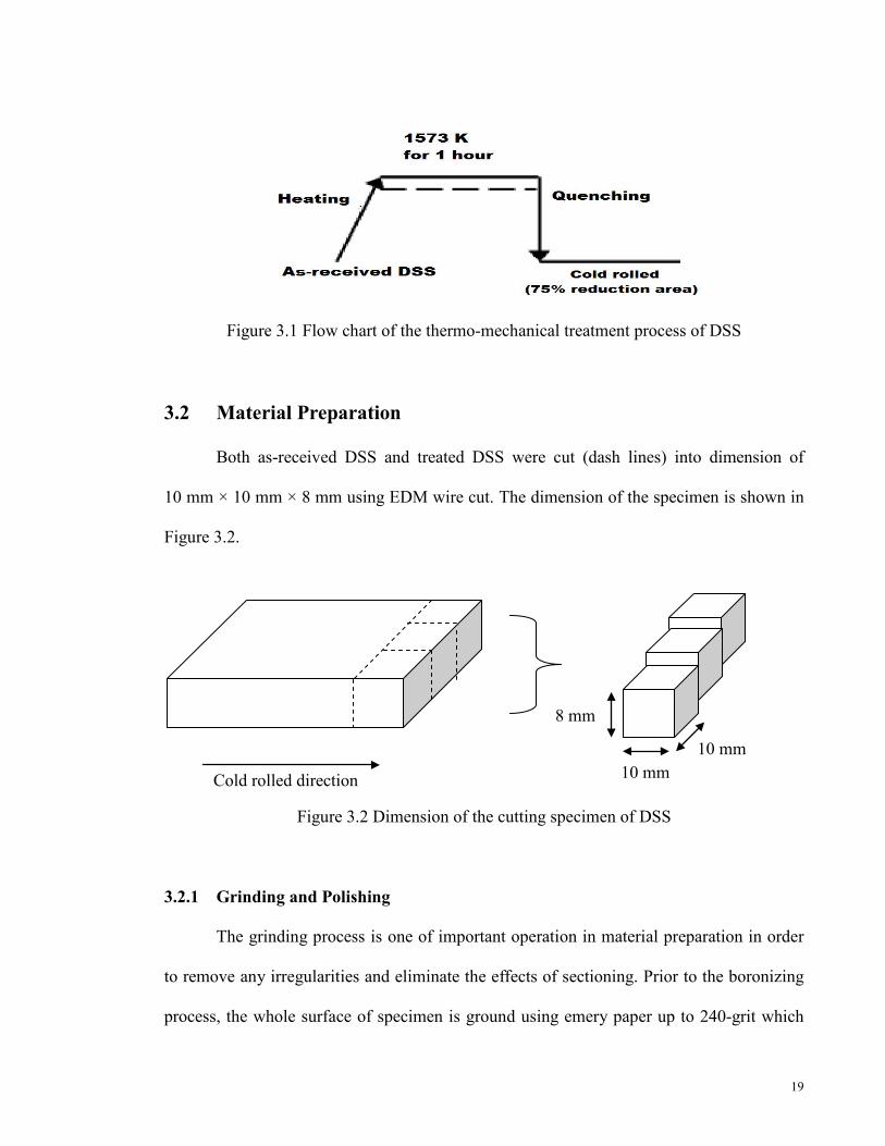
3.2 Material Preparation
Both as-received DSS and treated DSS were cut (dash lines) into dimension of
10 mm × 10 mm × 8 mm using EDM wire cut. The dimension of the specimen is shown in
Figure 3.2.
Figure 3.2 Dimension of the cutting specimen of DSS
3.2.1 Grinding and Polishing
The grinding process is one of important operation in material preparation in order
to remove any irregularities and eliminate the effects of sectioning. Prior to the boronizing
process, the whole surface of specimen is ground using emery paper up to 240-grit which
Cold rolled direction
8 mm
10 mm 10 mm
20
produces a surface roughness, Ra of 0.3µm (Hanis Ayuni, 2010). After the grinding process,
the specimen was washed using ethanol solution to remove contaminants.
3.2.2 Microstructure Evaluation
For microstructure evaluation, the cross-sectioned specimen was ground using
emery paper starting with the coarsest, 100-grit to the finest, 1200-grit to remove the oxide
layers. Polishing was performed in order to remove scratches and deformation from
grinding and to achieve a surface that is highly reflective, flat and defect free. The
specimen was polished until a mirror-like surface was obtained. A special etchant for
duplex stainless steel was prepared from hydrochloric acid (HCl) saturated with ferric
chloride (FeCl3) activated with a small amount of nitric acid (HNO3), based on the
proportion as mentioned by Voort (1984). The polished surface of the specimen was soaked
in the etchant solution for few seconds and then washed with distilled water.
3.3 Fabrication of Jigs and Dies
3.3.1 Container for the Boronizing Process
A stainless steel container was designed to conduct the conventional boronizing
process. Since boronizing is performed at high temperature, a container made from stainless
steel was used due to its high melting point which is between 1673 K and 1723 K. Besides
that, it is also known to have corrosion resistance qualities, high ductility, strength and
hardness. These properties are very suitable for the conventional boronizing process.
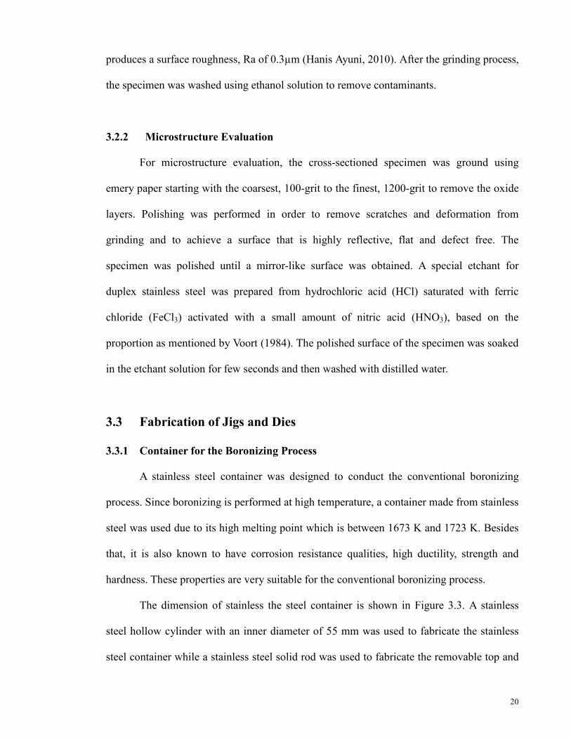
The dimension of stainless the steel container is shown in Figure 3.3. A stainless
steel hollow cylinder with an inner diameter of 55 mm was used to fabricate the stainless
steel container while a stainless steel solid rod was used to fabricate the removable top and
21
bottom cover. The solid rod was cut in a similar dimension to size of the inner diameter of
the hollow rod for it to be inserted as the bottom cover of the container. The bottom cover
was then welded to the container to ensure that it would not come off during the
experimental procedure. The removable top cover was also fabricated from a solid rod of
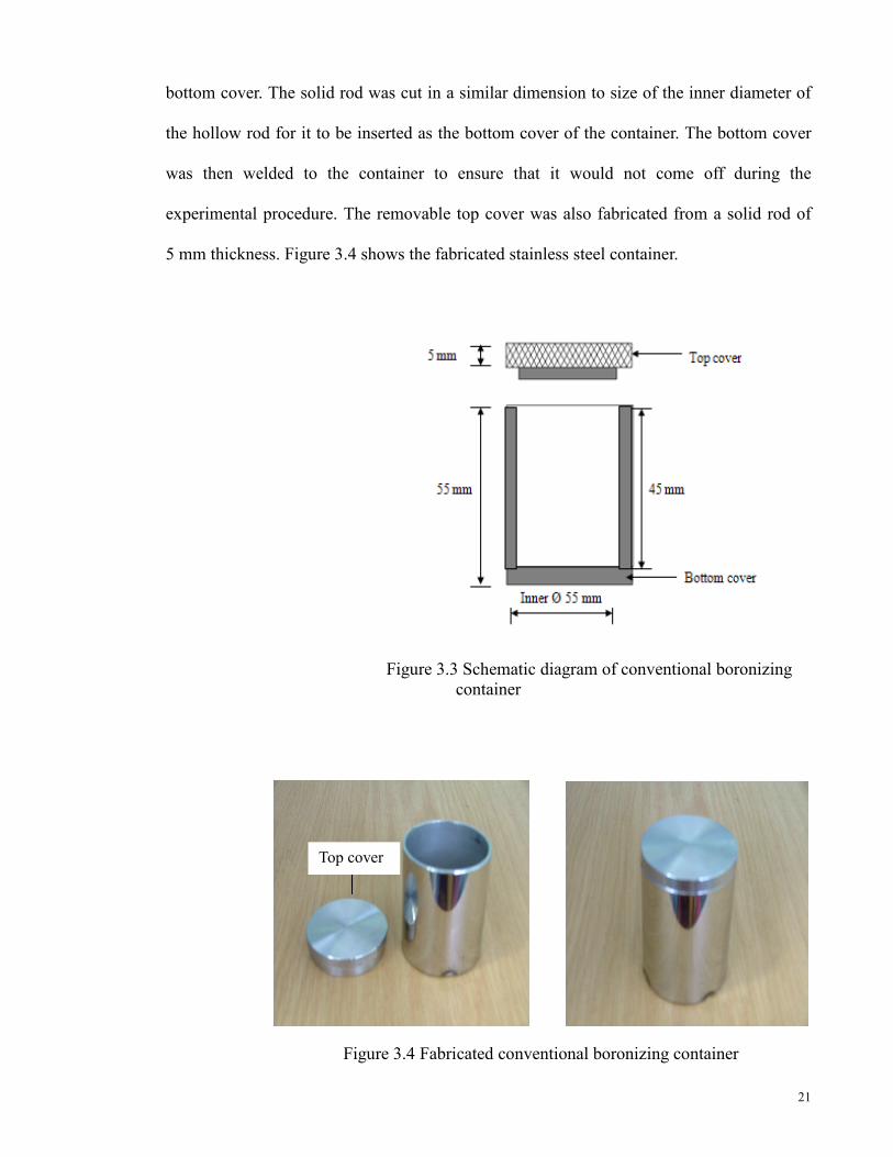
5 mm thickness. Figure 3.4 shows the fabricated stainless steel container.
Figure 3.3 Schematic diagram of conventional boronizing container
Figure 3.4 Fabricated conventional boronizing container
Top cover

22
3.3.2 Jigs and Dies for Forming Process
Specially designed jigs and dies were fabricated for superplastic deformation
process. High temperature resistance stainless steel was used for the fabrication of jigs and
dies. The upper temperature limit in the oxidation atmosphere is about 1273 K. The
drawing of jigs and dies is shown in Figure 3.5 (a), (b) and Figure 3.6 respectively. These
jigs and dies were set up for the forming process which is explained in section 3.5.
(a) Drawing dimension of upper jig
(b) Drawing dimension lower jig
Figure 3.5 Drawing dimension of lower and upper jigs that used for deformation
process

23
Figure 3.6 Dimension of dies from (a) top and (b) side views
3.4 Boronizing Process
In this work, pack-boronizing process was carried out. The specimen was
surrounded and packed with boron powder in the fabricated stainless steel container as
shown in Figure 3.7. Ekabor-1© boron powder was used as the boronizing agent in this
process. The container was tapped to make sure it was densely packed and also to prevent
air trap.
Figure 3.7 Schematic diagram of pack-boronizing set up inside the conventional
boronizing container
(b) Side View (a) Top View

24
Boronizing process was carried out at a temperature of 1223 K for 2, 4 and 6 hours
holding time in a tube furnace (Carbolite, type CTF 17/75/300) with controlled atmospheric
conditions using argon gas. Besides a offering a controlled atmospheric, Argon gas was
supplied to prevent oxidation at high temperature. After boronizing process completed, the
sample was allowed to cool in the furnace to room temperature. Figure 3.8 shows the flow
diagram for the boronizing process.
Figure 3.8 Flow diagram of boronizing process
3.5 Forming Process
Superplastic forming was carried out on the boronized specimen using a
compression testing machine (Instron) equipped with high-temperature furnace. The
specimen was compressed into a fabricated designed die. The sample was put in the die on
the end of lower jig. Both upper (movable crosshead) and lower jigs (fixed crosshead) were
placed in their specific positions located in the furnace. The picture and cross-section
diagram of the compression testing machine for the forming process set up is shown in
Figure 3.9.
Boronizing Temperature
Holding/ Boronizing time
Time
Temperature
Cool to room temperature
25
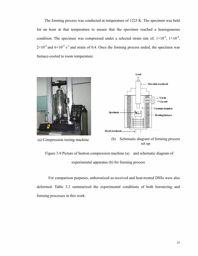
The forming process was conducted at temperature of 1223 K. The specimen was held
for an hour at that temperature to ensure that the specimen reached a homogeneous
condition. The specimen was compressed under a selected strain rate of; 1×10⁻³, 1×10⁻⁴,
2×10⁻⁴ and 6×10⁻⁵ s-1 and strain of 0.4. Once the forming process ended, the specimen was
furnace-cooled to room temperature.
Figure 3.9 Picture of Instron compression machine (a) and schematic diagram of
experimental apparatus (b) for forming process
For comparison purposes, unboronized as-received and heat-treated DSSs were also
deformed. Table 3.2 summarized the experimental conditions of both boronizing and
forming processes in this work.
(a) Compression testing machine (b) Schematic diagram of forming process set up

26
Table 3.2 Summary of experimental conditions for deformation process
* These samples, were exposed to heating at the same temperature for 6 hours without boron
powder
3.6 Characterization Methods
Several characterizations and analysis were performed in this study. X-ray diffraction
analysis (XRD) was carried out to confirm the presence of boride phases of boronized DSS.
The boronized layer was analyzed using an optical microscope and a scanning electron
microscope (SEM). The surface hardness of the specimen before and after the boronizing
process was measured using microhardness Vickers.
Sample Type of sample Boronizing
Process Superplastic Forming
Treated DSS
As-received DSS
Time (h)
Strain Rate (s-1)
Strain (mm/mm
)
Deformation time (s)
A-Treated-2hr / 2 1x10⁻⁴ 0.4 4000
B-Treated-4hr / 4 1x10⁻⁴ 0.4 4000
C-Treated-6hr / 6 1x10⁻⁴ 0.4 4000
D-As-received-6hr / 6 1x10⁻⁴ 0.4 4000
E-Treated-6hr-1 ×10⁻³ / 6 1x10⁻³ 0.4 400
F-Treated-6hr-2×10⁻⁴ / 6 2x10⁻⁴ 0.4 2000
G-Treated-6hr-6 × 10⁻⁵ / 6 6x10⁻⁵ 0.4 6666
H-Treated-6hrs*-1 ×10⁻⁴ / * 1x10⁻⁴ 0.4 4000
I-As-received-6hrs*-1
×10-4 / * 1x10⁻⁴ 0.4 4000

27
3.6.1 X-ray Diffraction Analysis (XRD)
X-ray diffraction (XRD) is a non-destructive technique to identify the crystalline
phases present in solid materials and powders and for analyzing structural properties (such
as stress, grain size, phase composition, crystal orientation, and defects) of the phases. The
XRD result patterns are like fingerprints of the material that is being examined.
In this study, chemical elements of the specimen, before and after the boronizing
process were confirmed using a Philips X’Pert MPD PW3040 XRD with CuKα radiation at
1.54056 Ǻ X-ray wavelength as shown in Figure 3.10. The specimen was scanned from
10° to 80° for 2θ angle at a step size of 0.020 and at a count time for 1.5 s at each step. The
surface of the specimen to be characterized by XRD analysis was cleaned with alcohol and
placed onto a glass slide.
Figure 3.10 X-Ray Diffraction analysis machine
3.6.2 Optical Microscopy
Morphology analysis can be made using the optical microscope for phase
identification. Visual examination enables material surface treatment to be identified and
characterized. In a reflected light microscope, the specimen is illuminated by frontal
lighting, which is accomplished by means of a small plain-glass reflector placed inside the
tube of the microscope (Zainul, 2004).

28
An optical microscope model Zeiss Axiotech with maximum 1000 times
enlargement was connected by a Panasonic digital camera model WV-CP410 to an image
analyzer. An MSQ software version 6.5 was used in this study as depicted in Figure 3.11.
The optical microscope was used in the microstructural analysis and measurement of
boronized layer thickness. The specimen was prepared and ground using various grades of
emery paper and polished until a mirror-like surface was achieved. The surface of the
specimen was then etched using a special etchant. Excess etchant is washed away with
distilled water and the specimen dried with a blower. The specimen was then ready to be
observed under a microscope using different magnifications.
Figure 3.11 Optical microscope model Zeiss Axiotech with connected digital camera and
image analyzer.
3.6.3 Scanning Electron Microscopy
With similar functions to that of an optical microscope, the scanning electron
microscope is used for deeper analytical microscopy because of its versatility and the wide
range of information it can provide. The SEM uses a focused beam instead of light for the
specimen imaging and obtains information on its structure and composition. The focused
Digital Camera

29
beam of high-energy electrons is scanned over the surface of a material and interacts with
the material, causing a variety of signals—secondary electrons (SE), backscattered
electrons (BSE), X-rays, photons, etc.— that may be used to characterize a material with
respect to specific properties. The signals are used to modulate the brightness on a display
CRT, thereby providing a high-resolution map of the selected material property.
In this study, Philips XL40 SEM as shown in Figure 3.13 was used to capture
images of specimen microstructure before and after the boronizing process. A conductive
sample is required for analyzing. For a non-conductive sample, generally specimens would
be coated using magnetic sputtering of gold. A sample preparation for SEM analysis is
similar to an optical microscope analysis. The sample to be analyzed was ground, polished
and etched to reveal its morphology. The sample was then put on the stub and placed in the
SEM chamber as shown in Figure 3.13.
Figure 3.12 Scanning electron microscope (SEM)

30
Figure 3.13 Microscope chamber of the SEM where the samples are placed for analysis
3.6.4 Microhardness Tester
According to Metals Handbook, hardness is defined as "Resistance of metal to
plastic deformation, usually by indentation”. It is the property of a metal-the ability to resist
being permanently, deformed (bent, broken, or having its shape changed), when load is
applied. The greater the hardness of the metal, the greater resistance it has to deformation.
In this study, hardness measurements were taken at the surface and the cross-section
of the boronized sample specimen using. A Vickers hardness test with a diamond indenter
test method was used. A load of 2N was applied and then the hardness reading was obtained
automatically after measuring the size of indentation. Mitutuyo microhardness tester model
MVK-H2 for the hardness test is shown in Figure 3.14.
Sample

31
Figure 3.14 Mitutuyo microhardness tester model MVK-H2
32
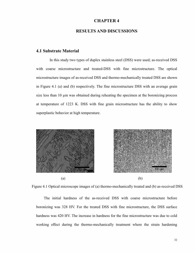
Figure 4.1 Optical microscope images of (a) thermo-mechanically treated and (b) as-received DSS
CHAPTER 4
RESULTS AND DISCUSSIONS
4.1 Substrate Material In this study two types of duplex stainless steel (DSS) were used; as-received DSS
with coarse microstructure and treated-DSS with fine microstructure. The optical
microstructure images of as-received DSS and thermo-mechanically treated DSS are shown
in Figure 4.1 (a) and (b) respectively. The fine microstructure DSS with an average grain
size less than 10 µm was obtained during reheating the specimen at the boronizing process
at temperature of 1223 K. DSS with fine grain microstructure has the ability to show
superplastic behavior at high temperature.
(a) (b)
The initial hardness of the as-received DSS with coarse microstructure before
boronizing was 328 HV. For the treated DSS with fine microstructure, the DSS surface
hardness was 420 HV. The increase in hardness for the fine microstructure was due to cold
working effect during the thermo-mechanically treatment where the strain hardening

33
occurred within the grains. Table 4.1 tabulates the characterizations of as-received DSS
(non-superplastic material) and treated-DSS (superplastic material).
Table 4.1 Characterization of as-received and treated DSSs
Characterization As-received DSS Treated DSS
Grain shape Elongated Equiaxed
Grain size - ~3 µm
Hardness 328 HV 420 HV
4.2 Boronizing Process of DSS
In this step, treated-DSS was boronized at temperature of 1223 K for 2, 4 and 6 hours
while as-received DSS was boronized for 6 hours for comparison. XRD analysis was
conducted for confirming the occurrence of boronizing process. Morphology analysis and
hardness test were also performed for detail characterization.
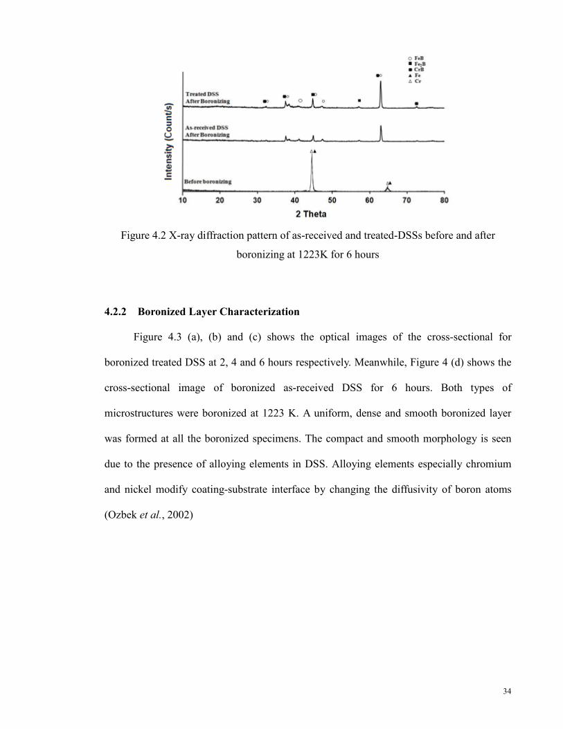
4.2.1 X-ray Diffraction Analysis (XRD)
The presence of boride phases on the surface of the boronized specimen were
confirmed by XRD analysis. Figure 4.2 demonstrates the XRD pattern of the as-received
and treated-DSS before and after boronizing for 6 hours at 1223 K. From the figure, the
presence of boride phases of FeB, Fe2B and CrB were detected on the surface of the
boronized specimen after boronizing. This results confirmed the successful occurrence of
boronizing process of the specimen. Further analysis of XRD is beyond the scope in this
study.
34
Figure 4.2 X-ray diffraction pattern of as-received and treated-DSSs before and after
boronizing at 1223K for 6 hours
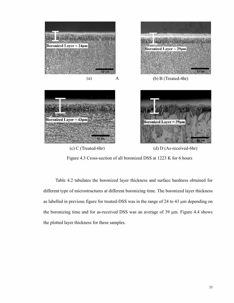
4.2.2 Boronized Layer Characterization
Figure 4.3 (a), (b) and (c) shows the optical images of the cross-sectional for
boronized treated DSS at 2, 4 and 6 hours respectively. Meanwhile, Figure 4 (d) shows the
cross-sectional image of boronized as-received DSS for 6 hours. Both types of
microstructures were boronized at 1223 K. A uniform, dense and smooth boronized layer
was formed at all the boronized specimens. The compact and smooth morphology is seen
due to the presence of alloying elements in DSS. Alloying elements especially chromium
and nickel modify coating-substrate interface by changing the diffusivity of boron atoms
(Ozbek et al., 2002)
35
Figure 4.3 Cross-section of all boronized DSS at 1223 K for 6 hours
(a) A
(c) C (Treated-6hr) (d) D (As-received-6hr)
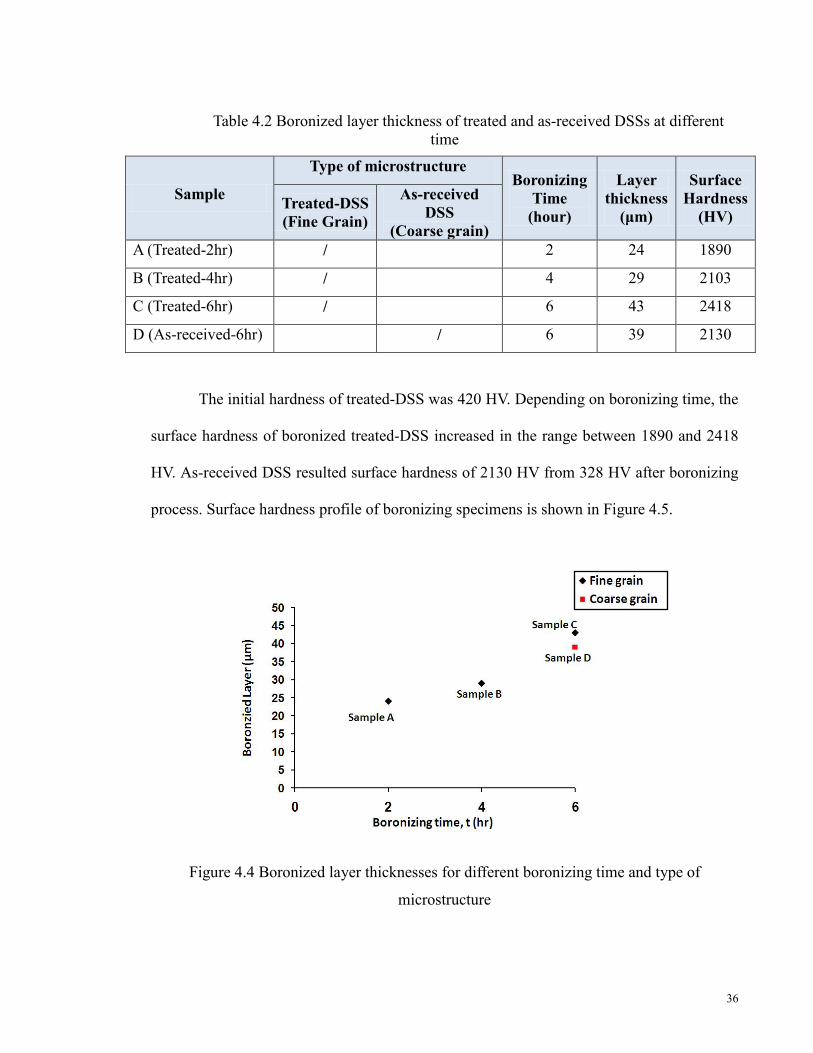
Table 4.2 tabulates the boronized layer thickness and surface hardness obtained for
different type of microstructures at different boronizing time. The boronized layer thickness
as labelled in previous figure for treated-DSS was in the range of 24 to 43 µm depending on
the boronizing time and for as-received DSS was an average of 39 µm. Figure 4.4 shows
the plotted layer thickness for these samples.
(b) B (Treated-4hr)
36
Table 4.2 Boronized layer thickness of treated and as-received DSSs at different time
The initial hardness of treated-DSS was 420 HV. Depending on boronizing time, the
surface hardness of boronized treated-DSS increased in the range between 1890 and 2418
HV. As-received DSS resulted surface hardness of 2130 HV from 328 HV after boronizing
process. Surface hardness profile of boronizing specimens is shown in Figure 4.5.
Figure 4.4 Boronized layer thicknesses for different boronizing time and type of
microstructure
Sample
Type of microstructure Boronizing
Time (hour)
Layer thickness
(μm)
Surface Hardness
(HV) Treated-DSS (Fine Grain)
As-received DSS
(Coarse grain) A (Treated-2hr) / 2 24 1890
B (Treated-4hr) / 4 29 2103
C (Treated-6hr) / 6 43 2418
D (As-received-6hr) / 6 39 2130
37
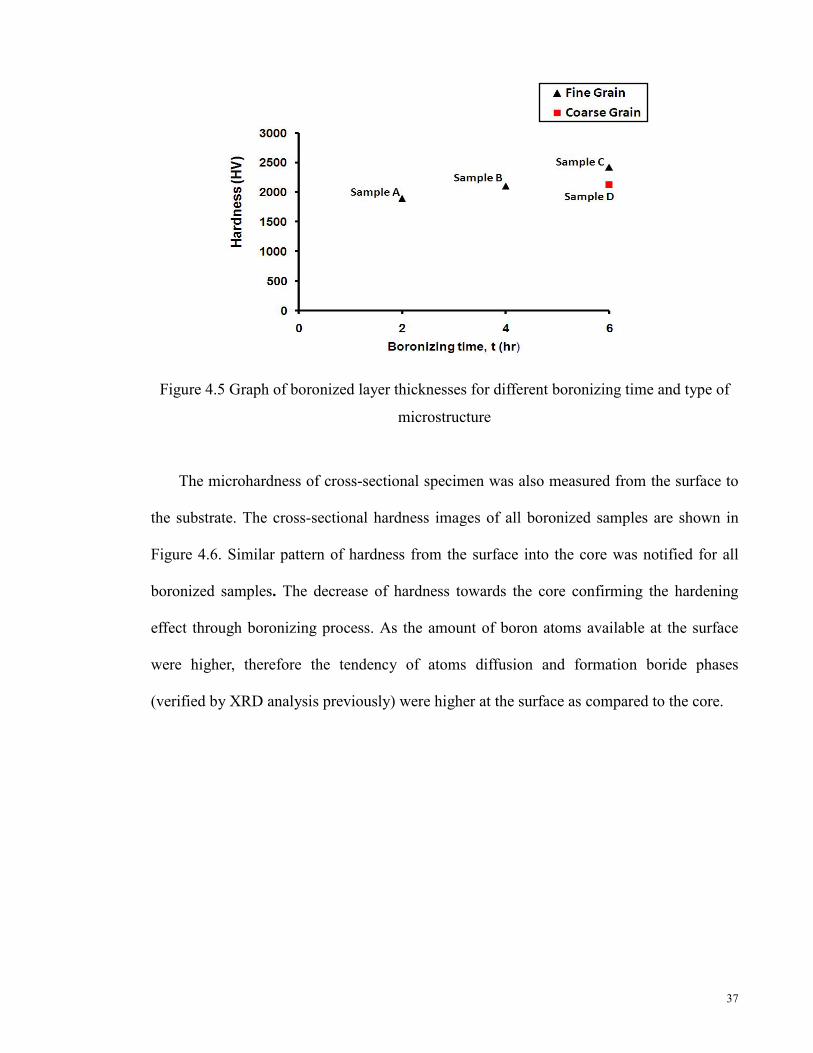
Figure 4.5 Graph of boronized layer thicknesses for different boronizing time and type of
microstructure
The microhardness of cross-sectional specimen was also measured from the surface to
the substrate. The cross-sectional hardness images of all boronized samples are shown in
Figure 4.6. Similar pattern of hardness from the surface into the core was notified for all
boronized samples. The decrease of hardness towards the core confirming the hardening
effect through boronizing process. As the amount of boron atoms available at the surface
were higher, therefore the tendency of atoms diffusion and formation boride phases
(verified by XRD analysis previously) were higher at the surface as compared to the core.

38
(a) Sample A (Treated-2hr) (b) Sample B (Treated-4hr)
(c) Sample C (Treated-6hr) (d) Sample D (As-received-6hr)
Figure 4.6 Microhardness of cross-sectional DSS, boronized at 1223 K for different hours
and different types of microstructure
The microhardness for boronized treated-DSS (Sample A, B and C) and boronized
as-received DSS (Sample D) from the surface towards the core were profiled in Figure 4.7.
For treated-DSS samples that boronized at different time, the profile revealed that longer
boronizing time promotes harder surface and thicker boronized layer. As boronizing time
increase, it allows more boron atoms to diffuse into the substrate. It was also noted that
both treated-DSS (Sample C) and as-received DSS (Sample D) which experienced the same
boronizing time duration produced 2418 HV and 2130 HV of surface hardness respectively.
The treated-DSS with fine grain having higher value of grain boundaries. Grain boundaries
are the most active area in microstructure and the diffusional of boron atoms would be

39
more active in this area. Therefore, higher value of surface hardness was obtained for
treated-DSS sample compared to as-received DSS.
Figure 4.7 Microhardness gradient profile of all boronized samples; A (Treated-2hr),
B (Treated-4hr), C (Treated-6hr) and D (As-received-6hr)
4.3 Forming Process
Heat forming of superplastic material; boronized treated-DSS was performed and also
for non-superplastic material; boronized as-received DSS were also performed for
comparison. Sample was deformed without the presence of boron powder. All boronized
samples were compressed at different conditions. From here, effect of different types of
grain microstructure, surface hardness and strain rate on the surface integrity of the
deformed boronized DSS were analyzed.
4.3.1 Grain Microstructure Effect on Flow Stress
Table 4.3 tabulates the effects of different microstructure and process condition on
flow stress. Boronized (Sample C and Sample D) and un-boronized (Sample H and Sample
I) specimens for both types of microstructure were deformed at the strain rate of 1x10⁻⁴ s-1
and strain of 0.4.

40
Table 4.3 Forming process conditions of boronized and un-boronized samples for
treated-DSS and as-received DSS
* These samples were exposed to heating at the same temperature for 6 hours without
boron powder
The stress-strain relationship for both boronized and un-boronized samples were
shown in Figure 4.8. The flow stress for as-received DSS (Sample I) and the treated-DSS
(Sample H) were about 37 MPa and 20 MPa respectively. The flow stress of as-received
DSS was higher than the treated one. After being boronized, the flow stress of both samples
increases remarkably to about 110 and 68 MPa respectively.
Figure 4.8 Stress-strain relationship of forming boronized samples; C (Treated-6hr) and D
(As-received-6hr) and un-boronized samples; H (Treated-6hrs-Unboron) and I
(As-received-DSS-6hrs-Unboron)
ample Type of sample Boronizing
Process Forming Process
Treated DSS
As-received DSS Time (h) Flow Stress
(MPa) C (Treated-6hr) / 6 68
D (As-received-6hr) / 6 110
H (Treated-6hrs-Unboron) / * 20
I (As-received-6hrs-Unboron) / * 37

41
Apparently, the presence of hard boronized layer increased the flow stress of the
samples. Similar trend of results were also reported for case-hardened (B. Hoffmann, 2001).
However, for Sample C (2418 HV) and sample D (2130 HV) it interesting to note that the
flow stress was not only depend on the hardness of the boronized layer. It was known that
the flow stress of Sample C (boronized treated-DSS) was lower than Sample D (boronized
as-received DSS) although having higher hardness. Sample C which having fine grain
microstructure is suggested affects the flow stress produced. When a load is applied to the
specimen which having fine grain microstructure, the deformation is due to grain boundary
diffusion and sliding, as a result of strain (Mohd Yusof H.A, 2010). Therefore, although
surface hardness of Sample C was higher than Sample D, the occurrence of fine grain of
boundary sliding was suggested to produce lower flow stress.
4.3.2 Surface Hardness Effect on Flow Stress
Table 4.4 shows the experimental conditions for this part. Treated-DSS that was
boronized at different time were superplastically deformed at strain rate 1x10⁻⁴ s-1 and
strain of 0.4.
42
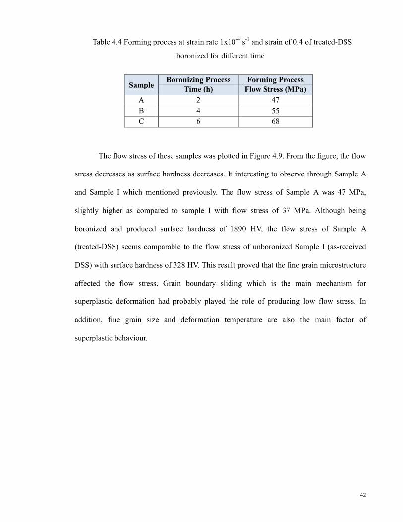
Table 4.4 Forming process at strain rate 1x10⁻⁴ s-1 and strain of 0.4 of treated-DSS
boronized for different time
The flow stress of these samples was plotted in Figure 4.9. From the figure, the flow
stress decreases as surface hardness decreases. It interesting to observe through Sample A
and Sample I which mentioned previously. The flow stress of Sample A was 47 MPa,
slightly higher as compared to sample I with flow stress of 37 MPa. Although being
boronized and produced surface hardness of 1890 HV, the flow stress of Sample A
(treated-DSS) seems comparable to the flow stress of unboronized Sample I (as-received
DSS) with surface hardness of 328 HV. This result proved that the fine grain microstructure
affected the flow stress. Grain boundary sliding which is the main mechanism for
superplastic deformation had probably played the role of producing low flow stress. In
addition, fine grain size and deformation temperature are also the main factor of
superplastic behaviour.
Sample Boronizing Process Forming Process
Time (h) Flow Stress (MPa) A 2 47 B 4 55 C 6 68

43
Figure 4.9 Flow stress of forming at temperature of 1223 K for boronized treated-DSS;
Sample A (Treated-2hr), Sample B (Treated-4hr) and Sample C (Treated-6hr)
4.3.2.1 Near-surface Microstructure: Effect of Surface Hardness and Grain
Microstructure
Near-surface microstructures of boronized treated-DSS (Sample A, Sample B and
Sample C) and as-received DSS (Sample D) after forming process is shown in Figure 4.10.
All these samples were deformed at strain rate of 1×10⁻⁴ s-1 and strain 0.4. Among the four
samples, Sample A (boronized treated DSS) has the lowest hardness and produced the
lowest flow stress. Contrary to Sample D (boronized as-received DSS), it has the highest
flow stress which has been explained in section 4.3.1. For different hardness samples;
Sample A, Sample B and Sample C, the near-surface morphology was similar to the
samples’ morphology before forming process especially for Sample A and Sample B. It
can be seen that although Sample D was boronized at the same duration time as Sample C,
the near-surface microstructure of Sample D (as-received DSS) was almost damaged until
the core while only a few micro-cracks were observed in Sample C (treated-DSS) . From
these results, it showed that hard boronized treated-DSS able to withstand the load applied
during deformation process and produced lower flow stress as compared to the boronized

44
as-received DSS. The fine grain microstructure of treated-DSS probably the factor to
withstand the applied load. As reported by Xu et. al (1996) that the smaller the grain size,
the more grain boundaries area and the higher the resistance is to crack propagation.
(a) Sample A (Treated-2hr) (b) Sample B (Treated-4hr)
(c) Sample C (Treated-6hr) (d) Sample D
(As-received-6hr)
Figure 4.10 Cross-sectional images of deformed boronized treated DSS and boronized
as-received at strain rate of 1×10⁻⁴ s-1 for strain 0.4 at temperature 1223 K
45
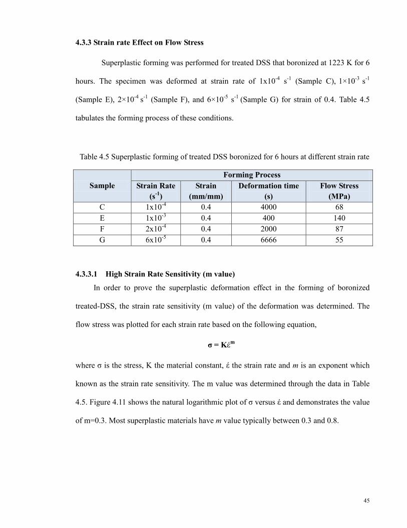
4.3.3 Strain rate Effect on Flow Stress
Superplastic forming was performed for treated DSS that boronized at 1223 K for 6
hours. The specimen was deformed at strain rate of 1x10⁻⁴ s-1 (Sample C), 1×10⁻³ s-1
(Sample E), 2×10⁻⁴ s-1 (Sample F), and 6×10⁻⁵ s-1 (Sample G) for strain of 0.4. Table 4.5
tabulates the forming process of these conditions.
Table 4.5 Superplastic forming of treated DSS boronized for 6 hours at different strain rate
4.3.3.1 High Strain Rate Sensitivity (m value)
In order to prove the superplastic deformation effect in the forming of boronized
treated-DSS, the strain rate sensitivity (m value) of the deformation was determined. The
flow stress was plotted for each strain rate based on the following equation,
σ = Kέm
where σ is the stress, K the material constant, έ the strain rate and m is an exponent which
known as the strain rate sensitivity. The m value was determined through the data in Table
4.5. Figure 4.11 shows the natural logarithmic plot of σ versus έ and demonstrates the value
of m=0.3. Most superplastic materials have m value typically between 0.3 and 0.8.
Sample Forming Process
Strain Rate (s-1)
Strain (mm/mm)
Deformation time (s)
Flow Stress (MPa)
C 1x10⁻⁴ 0.4 4000 68 E 1x10⁻³ 0.4 400 140 F 2x10⁻⁴ 0.4 2000 87 G 6x10⁻⁵ 0.4 6666 55

46
Figure 4.11 Strain rate sensitivity (m) for superplastic forming at different strain rate;
1x10⁻⁴ s-1 (Sample C), 1×10⁻³ s-1 (Sample E), 2×10⁻⁴ s-1 (Sample F), and 6×10⁻⁵ s-1 (Sample
G)
In Figure 4.12, forming at high strain rate resulted flow stress of about 140 MPa
(Sample E). At a fixed temperature, as strain rate decreased, the flow stress was also
decreased. The flow stress of lower strain rate were 87, 68, 55 MPa for Sample F, Sample C
and Sample G respectively. Generally, increasing strain rate leads to the augmentation of
flow stress. The results here suggested that the boronizing would hardened the substrate
surface and therefore increase during high temperature forming. It also suggests that the
flow stress of the surface-hardened substrate could be reduced through superplasticity.

47
Figure 4.12 Stress-strain relationship for boronized treated DSS deformed at 1x10⁻⁴ s-1
(Sample C), 1×10⁻³ s-1 (Sample E), 2×10⁻⁴ s-1 (Sample F), and 6×10⁻⁵ s-1 (Sample G)
4.3.3.2 Near-surface Microstructure: Effect of Strain Rate
In this part with reference to Figure 4.12 previously, superplastic forming was done
on boronized treated-DSS that boronized for 6 hours. FESEM images in Figure 4.13 shows
the near-surface microstructure of boronized treated-DSS after forming at 1223 K and
strain rate of 0.4 for different strain rate;1×10⁻³ s-1 (Sample E), 2×10⁻⁴ s-1 (Sample F) and
6×10⁻⁵ s-1 (Sample G). With reference to Figure 4.12 previously, forming at the highest
strain rate produced high flow stress. From the FESEM images, it showed that at highest
strain rate leads to disintegration of boronized layer (Figure 4.13(a)). At the lower strain
rate, the flow stress produced was 87 MPa (Figure 4.13 (b)) and surface disintegration was
noticed through the microcracks formations into the substrate. In Figure 4.13 (c) there is no
sign of surface disintegration after deformation process.

48
(a) Sample E ( 1×10⁻³ s-1) (b) Sample F (2×10⁻⁴ s-1)
(c) Sample G (6×10⁻⁵ s-1)
Figure 4.13 FESEM images of boronized treated-DSS deformed at 1223 K for different
strain rate; 1×10⁻³ s-1 (Sample E), 2×10⁻⁴ s-1 (Sample F) and 6×10⁻⁵ s-1 (Sample G) and
strain of 0.4
From these results, it showed that when forming using superplastic material
(treated-DSS), the hard boronized layer is able to withstand the load applied without cracks
and produced low flow stress. It is important to notice that in order to be able to form
surface hardened material without compromising on the surface disintegration, the flow
stress during forming must be kept as low as possible. This could be achieved through the
control of boronizing and heat forming parameters with the exploitation of superplastic
deformation process.
49
CHAPTER 5
CONCLUSIONS
5.1 Conclusions
In this study, the effects of microstructure, strain rate and surface hardness on the
forming process of the boronized treated-DSS were investigated. Characterizations on
surface hardness, boronized layer and flow stress behaviour of the samples were done.
Depending on boronizing time, boronized layer thickness of treated-DSS varied from 24 to
43 µm and surface hardness formed was in the range of 1890 to 2418 HV. Long duration
time leads to the increment of boronized layer thickness and surface hardness. Boronized
as-received DSS possesses a surface hardness and a boronized layer thickness of 2130 HV
and 39 µm respectively.
For different surface hardness of boronized treated-DSS, the flow stress of high
temperature forming was varied from 47 to 68 MPa. The flow stress is also increased as the
hardness increases. Depending on types of microstructure, boronized treated-DSS produced
lower flow stress as compared to boronized as-received DSS.
From the study, the following conclusions also can be made:
1. The flow stress during the forming process is strongly dependent on the surface
hardness of the boronized layer, strain rate and initial microstructure conditions of
the substrate.
2. Through superplasticity, the flow stress of the surface hardened sample can be kept
or maintained as low as possible without creating any sign of surface disintegration.

50
5.2 Recommendations
Some suggestions for further study and development through the findings are stated as
follows:
• The microstructure characterization such as EPMA analysis can be look into to
evaluate the boron content of boronized samples.
• Mechanical testing such as wear test should be studied to investigate the product’s
performance.
• The processing techniques using different dimension of jigs and dies to form a
product or parts
• The application using the results produced and its potential usage in the industry
such as formation gear.

51
REFERENCES
Arieli, A., Mukherjee, A.K., (1980). A model for the rate-controlling mechanism in superplasticity. Materials Science and Engineering. 45 (1), 61-70
Balokhonov, R.R., Stefanov, Yu.P., Makarov, P.V., Smolin, I.Yu., (2000). Deformation and fracture of surface-hardened materials at meso- and macroscale levels. Theoretical and Applied Fracture Mechanic. 33, 9-15
Bloor, D., Brook, R.J., Flenings, M.C., Mahgan, S., (1994). The encyclopedia of advanced materials., Vol 4, Elsevier Science Ltd., Pergamon, UK., 2712-2722 Cabrera, J.M., Mateo, A., Llanes, L., Prado, J.M., Anglada, M., (2003). Hot deformation of
duplex stainless steels. Journal of Materials Processing Technology. 143-144, 321-325
Carrino, L., Giuliano, G., Polini, W., (2003). A method to characterize superplastic materials in comparison with alternative methods. Journal of Materials Processing Technology. 138, 417 – 422 Chandra, N., (2002). Constitutive behavior of superplastic materials. International Journal of Non-Linear Mechanics. 37,461-484 Friedman, P.A., Luckey, S.G., (2004). On the expanded usage of superplastic forming of aluminium sheet for automotive applications. Material Science Forum. 447-448, 199-204 Gifkins, R.C., (1976). Grain-boundary sliding and its accommodation during creep and superplasticity. Met. Trans. 7, 1225-1232
Han, Y.S., Hong, S.H., (1997). The effects of thermo-mechanical treatments on superplasticity of Fe-24Cr-7Ni-3Mo-0.14N duplex stainless steel. Scripta Materialia, 36 (5), 557-563 Hasan, R., (2005). Development of superplastic boronizing using duplex stainless steel, Master Sc. Eng. Thesis, University of Malaya, Kuala Lumpur, Malaysia.
Henrik, S., Rolf, S., (2006). Fracture toughness of a welded duplex stainless steel. Engineering Fracture Mechanics. 73, 377-90
Hertzberg, R.W., (1996). Deformation and Fracture Mechanics of Engineering Materials, 4th edn. New York: John Wiley & Sons.

52
Hoffmann, B., Vo¨hringer, O., Macherauch, E., (2001). Effect of compressive plastic deformation on mean lattice strains, dislocation densities and flow stresses of martensitically hardened steels. Materials Science and Engineering A. 319–321, 299–303 Jauhari, I., Ogiyama, H., Tsukuda, H., (2002). Superplastic Diffusion Bonding of Duplex Stainless Steel. Proceedings of 2nd. World Engineering Congress, 22-25
Jiménez, J.A., Frommeyer, G., Carsí, M., Ruano, O. A., (2001). Superplastic properties of a δ/γ stainless steel. Materials Science and Engineering A. 307, 134-142
Keddam, M., Chentaouf, S.M., (2005). A diffusion model for describing the bilayer growth (FeB/Fe2B) during the iron powder-pack boriding. Applied Surface Science. 252 (2), 393-399 Kirthi, B., (2007). An approach to inverse modeling through the integration of artificial neural networks and genetic algorithms, Master Sc. in Mechanical Engineering Thesis, University of Kentucky, United States of America
Kohser, R.A., DeGarmo, E.P., Black, J.T., & Klamecki, B.E., (2003). Materials and Process in Manufacturing 8th edition, John Wiley & Sons, 134
Kum, D.W., Oyama, T., Sherby, O.D., Ruano, O.A., Wadsworth, J., (1984). In S.P. Agrawal (ed.) Superplastic Forming. American Society for Metals, Metals Park, 32.
Langdon, T.G., (1970). Grain boundary sliding as a deformation mechanism during creep. Philosophical Magazine. 22, 689-700 Lutfullin, R.Y., Imayev, R.M., Kaibyshev, O.A., Hismatullin, F.N., Imayev V.M., (1995). Superplasticity and solid state bonding of the TiAl intermetallic compound with micro and submicrocrystalline structure. Scripta Metallurgica et Materialia. 33, 9, 1445-1449 Meric C., Sahin S., Yilmaz S.S., (2000). Investigation of the effect on boride layer of powder particle size used in boronizing with solid boron-yielding substances. Materials Research Bulletin. 35, 2165-2172 Miyamoto, H., Mimaki, T., Hashimoto, S. (2001). Superplastic deformation of micro-specimens of duplex stainless steel. Materials Science Engineering A. 319-321, 779-783 Mohd Yusof H. A., (2010). Superplastic Boronizing of Duplex Stainless Steel through Dual Compression Method, Masters Sc. Eng. Thesis, University of Malaya, Kuala Lumpur, Malaysia. Mukherjee, A.K., (2002). An examinationof the constitutive equation for elevated temperature plasticity. Materials Science and Engineering A. 322 (1-2), 1-22 Mukherjee, A.K., (1971). The rate controlling mechanism in superplasticity. Materials Science and Engineering. 8 (2), 83-89
53
Muthupandi, V., Bala Srinivasan, P., Seshadri, S. K., and Sundaresan, S., Shankar, V., (2005). Effect of nickel and nitrogen addition on the microstructure and mechanical properties of power beam processed duplex stainless steel (UNS 31803) weld metals. Materials Letters. 59, 2305-2309
Ozbek, I., Konduk, B.A., Bindal, C., Zeytin, S., Ucisik, A.H., (2002). Characterization of borided AISI 316L stainless steel implant. Vacuum. 65, 521-525
Sinha A.K., (1991). Boronizing, ASM Handbook, OH, USA. Journal of Heat Treatment. 4, 437-447
Superform Metals Limited (Eds.). (1988). Superplastic Aluminium Forming, Gulliver Press Ltd., United Kingdom Tsuzuka, T., Takahashi, A., and Sakamoto, A., (1991). Application of superplastic forming for aerospace components, In Hori, S., Tokizane, M. and Furushiro, N. (eds). Superplasticity in Advanced Materials, 611-620 Tsuzaki, K., Xiaoxu, H., Maki, T., (1996). Mechanism of dynamic continuous recrystallization during superplastic deformation in a microduplex stainless steel. Acta Metallurgica. 44 (11), 4491-4499
Valiev, R. Z., (2000). Superplastic Behaviour of Micro-and Nanograined Materials. NATO Science Series, 367, 491-506
Vipin, J., Sundararajan, G., (2002). Influence of the pack thickness of the boronizing mixture on the boriding of steel. Surface and Coatings Technology. 149, 21–26
Walser, B., Ritter, U., (1985). In B. Bandelet and M. Suery (eds.) Superplastic Centre National de la Recheache Scientifique, Paris, 15
Xing, H.L., Wang, C.W., Zhang, K.F., Wang, Z.R, (2004). Recent Development in the Mechanics of Superplasticity and Its Applications. Journal of Materials Processing Technology. 151, 196-202
Xu. C. H., Xi J. K., and Gao W., (1997). Isothermal superplastic boronizing of high carbon
and low alloy steels. Scripta Maerialia. 34 (3), 455-461
Xun, Y.W., Tan, M.J., (2000). Applications of superplastic forming and diffusion bonding to hollow engines blades. Journal of Materials processing Technology. 99, 80-85 Xu, C. H, Xi, J.K, and Gao, W. (1996), Isothermal superplastic boronizing of high carbon steel and low alloy steels. Scripta Materialia. 34(3). 455-461

54
Yusof, H.A.M., Jauhari I., Saidan, R., (2011). Superplastic boronizing of duplex stainless steel under dual compression method. Materials Science and engineering A. 528, 8106-8110 Zainul, H., (2004). Optical Microscopy, A 2-Day Short Course on Materials Analysis, Characterization and Evaluation, University of Malaya, Kuala Lumpur, Malaysia. Zelin, M.G., Mukherjee, A.K., (1996). Geometrical aspects of superplastic flow. Materials Science and Engineering A. 208, 210-225 Zucchi, F., Grassi, V., Monticelli, C., Trabanelli, G., (2006). Hydrogen embrittlement of duplex stainless steel under cathodic protection in acidic artificial sea water in the presence of sulphide ion. Corrosion Science. 48, 522–530
INTERNET REFERENCES
URL: 1) http://www.metalwebnews.com/howto/superplastic-forming/superplastic-
forming.html
URL: 2) http://www.nap.edu/html/materials_and_man/0309036976/HTML
URL: 3) http://www.asminternational.org/asmenterprise
URL: 4) http://www.lapump.com/html/duplex_stainless steel.html

55
PUBLICATIONS Journal I. Jauhari, H.A.M Yusof and R. Saidan. Superplastic boronizing of duplex stainless steel
under dual compression method. Materials Science and Engineering A. Vols. 528 (2011) pp.
8106-8110.
R. Saidan and I. Jauhari. A Study on the High Temperature Forming Effect of Boronized
Duplex Stainless Steel. (In-review in Journal of Materials Processing Technology)
Conference
R. Saidan and I. Jauhari. (2012) Effect of Superplastic Forming on Boronized Duplex
Stainless Steel. Proceeding of 6th International Conference on Advanced Computational
Engineering and Experimenting (ACEX-2012). 1-4 July 2012. Istanbul, Turkey.