rosettacnc g-code language · rosettacnc g-code language 1/39 1. supported g codes the following...
TRANSCRIPT
RosettaCNC G-code language
1/4
Document release 2
RosettaCNC G-code language
2/4
RosettaCNC G-code language
All rights reserved on this manual. No part of this document can be copied or reproduced in any form without prior written authorisation. RosettaCNCMotion® does not insure or guarantee its contents and explicitly declines all liability related to the guarantee of its suitability for any purpose. Theinformation in this document can be changed without notice. RosettaCNC Motion® shall not be held liable for any error or omission in this document.RosettaCNC Motion® is a registered trademark.
Information
Document: MDUROSETTACNCSOFTWAREGCODEDescription: RosettaCNC G-code languageLink: https://wiki.rosettacnc.com/doku.php/software/mdurosettacncsoftwaregcodeRelease documento Descrizione Note Data01 First release / 17/01/201802 Minor changes / 29/01/2019
References
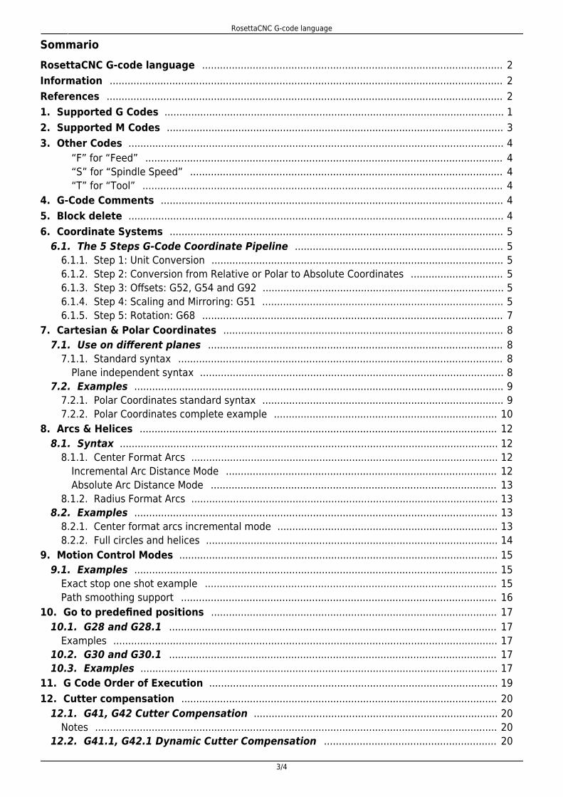
This manual explains the programming language used by the RosettaCNC software. All the implementation details are refer tothe software version 1.5. This version can be identified by open the “Help” menu → “About RosettaCNC”. Then it appears:
RosettaCNC G-code language
3/4
SommarioRosettaCNC G-code language 2 ..................................................................................................... Information 2 .................................................................................................................................... References 2 ..................................................................................................................................... 1. Supported G Codes 1 .................................................................................................................. 2. Supported M Codes 3 ................................................................................................................. 3. Other Codes 4 ..............................................................................................................................
“F” for “Feed” 4 ........................................................................................................................ “S” for “Spindle Speed” 4 ......................................................................................................... “T” for “Tool” 4 .........................................................................................................................
4. G-Code Comments 4 ................................................................................................................... 5. Block delete 4 .............................................................................................................................. 6. Coordinate Systems 5 ................................................................................................................
6.1. The 5 Steps G-Code Coordinate Pipeline 5 ...................................................................... 6.1.1. Step 1: Unit Conversion 5 .................................................................................................. 6.1.2. Step 2: Conversion from Relative or Polar to Absolute Coordinates 5 ............................... 6.1.3. Step 3: Offsets: G52, G54 and G92 5 ................................................................................. 6.1.4. Step 4: Scaling and Mirroring: G51 5 ................................................................................. 6.1.5. Step 5: Rotation: G68 7 .....................................................................................................
7. Cartesian & Polar Coordinates 8 .............................................................................................. 7.1. Use on different planes 8 ...................................................................................................
7.1.1. Standard syntax 8 ............................................................................................................. Plane independent syntax 8 ......................................................................................................
7.2. Examples 9 ............................................................................................................................ 7.2.1. Polar Coordinates standard syntax 9 ................................................................................. 7.2.2. Polar Coordinates complete example 10 ...........................................................................
8. Arcs & Helices 12 ........................................................................................................................ 8.1. Syntax 12 ...............................................................................................................................
8.1.1. Center Format Arcs 12 ....................................................................................................... Incremental Arc Distance Mode 12 ........................................................................................... Absolute Arc Distance Mode 13 ................................................................................................
8.1.2. Radius Format Arcs 13 ....................................................................................................... 8.2. Examples 13 ..........................................................................................................................
8.2.1. Center format arcs incremental mode 13 .......................................................................... 8.2.2. Full circles and helices 14 ..................................................................................................
9. Motion Control Modes 15 ........................................................................................................... 9.1. Examples 15 ..........................................................................................................................
Exact stop one shot example 15 .................................................................................................. Path smoothing support 16 ..........................................................................................................
10. Go to predefined positions 17 ................................................................................................ 10.1. G28 and G28.1 17 ..............................................................................................................
Examples 17 ................................................................................................................................. 10.2. G30 and G30.1 17 .............................................................................................................. 10.3. Examples 17 ........................................................................................................................
11. G Code Order of Execution 19 ................................................................................................. 12. Cutter compensation 20 ..........................................................................................................
12.1. G41, G42 Cutter Compensation 20 .................................................................................. Notes 20 .......................................................................................................................................
12.2. G41.1, G42.1 Dynamic Cutter Compensation 20 ..........................................................
RosettaCNC G-code language
4/4
Notes 20 ....................................................................................................................................... 12.3. Tool compensation entry options 21 ..............................................................................
Common Cutter Radius Compensation Errors 21 ......................................................................... 12.4. Examples 22 ........................................................................................................................
12.4.1. Easy Lead-in 22 ............................................................................................................... 12.4.2. Auto 23 ............................................................................................................................
13. Macro programming 25 ........................................................................................................... 14. G-code variables 26 ..................................................................................................................
14.1. Description 26 .................................................................................................................... 14.2. Vacant or Empty Variables 27 .........................................................................................
15. Local variables 29 ..................................................................................................................... 16. Arithmetic Logic & Statements 30 .........................................................................................
16.1. Binary Operators 30 .......................................................................................................... About equality and floating-point values 30 .................................................................................
16.2. Functions 30 ....................................................................................................................... 17. Looping & Branching 31 ..........................................................................................................
17.1. Unconditional Branching 31 ............................................................................................. 17.2. Conditional Branching 31 ................................................................................................. 17.3. IF-THEN Option 31 ............................................................................................................. 17.4. While Loop 31 ..................................................................................................................... 17.5. Example 31 ..........................................................................................................................
18. Custom Macro calls 33 ............................................................................................................. 19. Subroutines 34 .......................................................................................................................... 1. User Tool Change Subprogram 35 ...........................................................................................
Examples 35 ................................................................................................................................... Manual Tool Change 35 ................................................................................................................ Automatic Tool Change 35 ...........................................................................................................
21. Messages & Media 37 .............................................................................................................. 21.1. Parameters meaning 37 ....................................................................................................
Notes 37 .................................................................................................................................... 21.2. Examples 37 ........................................................................................................................
Modal window messages 37 ......................................................................................................... HUD messages 38 ........................................................................................................................
22. Acknowledgement 39 ...............................................................................................................

RosettaCNC G-code language
1/39
1. Supported G Codes
The following table describes supported G-Code commands.The G-codes and M-codes called in the same line of a G-code file are executed accordingly to G Code Order of Execution.
In the following axes means one or more of X,Y,Z,A,B,C, along with a corresponding floating point value for a specified axis.
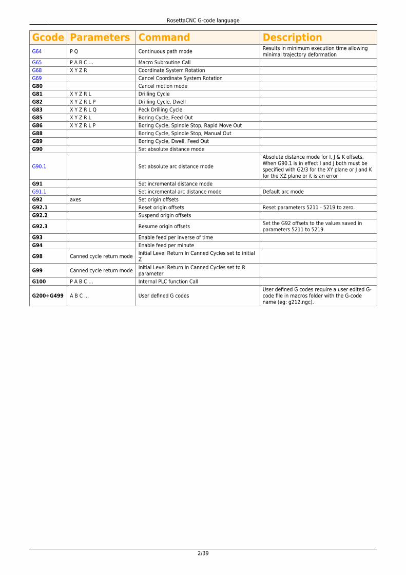
Gcode Parameters Command DescriptionG0 axes Straight traverse Traverse at maximum velocityG1 axes F Straight feed Move at feed rate FG2 axes F P IJK or R Clockwise arc feed Arc at feed rate FG3 axes F P IJK or R Counterclockwise arc feed Arc at feed rate FG4 P Dwell Pause for P secondsG9 axes F Exact Stop (non-modal) Move at feed rate F and stop at the endG10 L1 P axes Set Tool Table EntryG10 L10 P axes Set Tool Table, Calculated, WorkpieceG10 L2 P axes Coordinate System Origin SettingG10 L2 P axes Coordinate Origin Setting CalculatedG15 Switch to Cartesian coordinatesG16 Switch to polar coordinatesG17 Select XY arc planeG18 Select XZ arc planeG19 Select YZ arc plane
G20 Select inches mode All G-code from this point on will beinterpreted in inches
G21 Select mm mode All G-code from this point on will beinterpreted in millimetres
G28 axes Go to G28 position Optional axes specify an intermediate pointG28.1 axes Set G28 position The current machine position is recordedG30 axes Go to G30 position Optional axes specify an intermediate pointG30.1 axes Set G30 position The current machine position is recordedG40 Disable Cutter Compensation
G41 D I Enable Cutter Compensation left of programmedpath
G41.1 D L Enable Dynamic Cutter Compensation left ofprogrammed path
G42 D I Enable Cutter Compensation right ofprogrammed path
G42.1 D L Enable Dynamic Cutter Compensation right ofprogrammed path
G43 H Enable Tool Length Compensation H argument is optional, if it is not specified thecurrent tool is used.
G43.1 X Y Z Enable Dynamic Tool Length CompensationTool compensation is enabled considering thespecified offsets X, Y and Z. The argumentsX,Y and Z are optional but at least one shouldbe specified.
G43.2 H Apply additional Tool Length Offset Add the offsets due to the tool specified withthe H argument to the offsets already in use.
G49 Cancel Tool Length CompensationG50 Disable scalingG51 X Y Z and I J K or P Enable scaling
G52 axes Local Work Shift The values entered are added to all workoffsets
G53 Select absolute coordinates Non-Modal: Applies only to current block
G54 Select coord system 1G54 is typically used as the “normal”coordinate system and reflects the machineposition
G55 Select coord system 2G56 Select coord system 3G57 Select coord system 4G58 Select coord system 5G59 Select coord system 6G59.1 Select coord system 7G59.2 Select coord system 8G59.3 Select coord system 9G61 Set exact path modeG61.1 Set exact stop mode Motion will stop between each G-code block
RosettaCNC G-code language
2/39
Gcode Parameters Command DescriptionG64 P Q Continuous path mode Results in minimum execution time allowing
minimal trajectory deformationG65 P A B C … Macro Subroutine CallG68 X Y Z R Coordinate System RotationG69 Cancel Coordinate System RotationG80 Cancel motion modeG81 X Y Z R L Drilling CycleG82 X Y Z R L P Drilling Cycle, DwellG83 X Y Z R L Q Peck Drilling CycleG85 X Y Z R L Boring Cycle, Feed OutG86 X Y Z R L P Boring Cycle, Spindle Stop, Rapid Move OutG88 Boring Cycle, Spindle Stop, Manual OutG89 Boring Cycle, Dwell, Feed OutG90 Set absolute distance mode
G90.1 Set absolute arc distance modeAbsolute distance mode for I, J & K offsets.When G90.1 is in effect I and J both must bespecified with G2/3 for the XY plane or J and Kfor the XZ plane or it is an error
G91 Set incremental distance modeG91.1 Set incremental arc distance mode Default arc modeG92 axes Set origin offsetsG92.1 Reset origin offsets Reset parameters 5211 - 5219 to zero.G92.2 Suspend origin offsets
G92.3 Resume origin offsets Set the G92 offsets to the values saved inparameters 5211 to 5219.
G93 Enable feed per inverse of timeG94 Enable feed per minute
G98 Canned cycle return mode Initial Level Return In Canned Cycles set to initialZ
G99 Canned cycle return mode Initial Level Return In Canned Cycles set to Rparameter
G100 P A B C … Internal PLC function Call
G200÷G499 A B C … User defined G codesUser defined G codes require a user edited G-code file in macros folder with the G-codename (eg: g212.ngc).
RosettaCNC G-code language
3/39
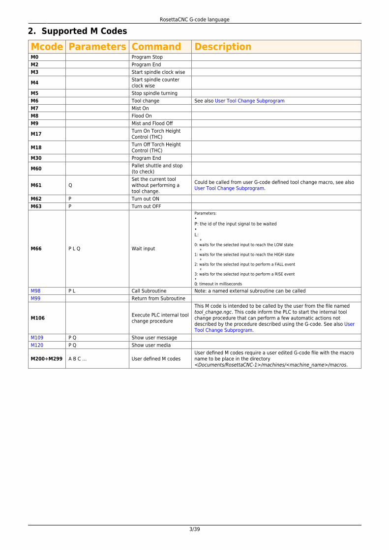
2. Supported M Codes
Mcode Parameters Command DescriptionM0 Program StopM2 Program EndM3 Start spindle clock wise
M4 Start spindle counterclock wise
M5 Stop spindle turningM6 Tool change See also User Tool Change SubprogramM7 Mist OnM8 Flood OnM9 Mist and Flood Off
M17 Turn On Torch HeightControl (THC)
M18 Turn Off Torch HeightControl (THC)
M30 Program End
M60 Pallet shuttle and stop(to check)
M61 QSet the current toolwithout performing atool change.
Could be called from user G-code defined tool change macro, see alsoUser Tool Change Subprogram.
M62 P Turn out ONM63 P Turn out OFF
M66 P L Q Wait input
Parameters:•P: the id of the input signal to be waited•L: ⚬0: waits for the selected input to reach the LOW state ⚬1: waits for the selected input to reach the HIGH state ⚬2: waits for the selected input to perform a FALL event ⚬3: waits for the selected input to perform a RISE event•Q: timeout in milliseconds
M98 P L Call Subroutine Note: a named external subroutine can be calledM99 Return from Subroutine
M106 Execute PLC internal toolchange procedure
This M code is intended to be called by the user from the file namedtool_change.ngc. This code inform the PLC to start the internal toolchange procedure that can perform a few automatic actions notdescribed by the procedure described using the G-code. See also UserTool Change Subprogram.
M109 P Q Show user messageM120 P Q Show user media
M200÷M299 A B C … User defined M codesUser defined M codes require a user edited G-code file with the macroname to be place in the directory<Documents/RosettaCNC-1>/machines/<machine_name>/macros.

RosettaCNC G-code language
4/39
3. Other Codes
Simple G-code commands are used for setting the speed, feed, and tool parameters.
“F” for “Feed”
The F command sets the feed rate; the machine operates at the set feed rate when G1 is used, and subsequent G1 commandswill execute at the set F value.
If the feed rate (F) is not set once before the first G1 call, either an error will occur or the machine will operate at its “default”feed rate.An example of a valid F command: G1 F1500 X100 Y100
“S” for “Spindle Speed”
The S command sets the spindle speed, typically in revolutions per minute (RPM). An example of a valid S command: S10000
“T” for “Tool”
The T command is used to set the id of the tool to be loaded with the M6 command.The typical syntax to load the tool with id 1 would be:M6 T1
Notes
If the automatic tool change feature is enabled in the board settings, the M6 command produces a toolchange handled by RosettaCNC internal code that can by adapted using dedicated parameters.
Setting the Tool Change Type option to Custom Macro in the board settings the user can customise thetool change procedure. if the option is enabled the M6 command will look into the machine macro folderand execute the G-code file named tool_change.ngc. In this file the user can specify any supported G-codecommand to perform the tool change procedure as required by the specific machine. To see a referenceimplementation of the file tool_change.ngc please take a look to User Tool Change Subprogram.
4. G-Code Comments
The following syntaxes are supported:
(…) : simple comment between brackets; : simple comment till the end of the line started with a semi column
5. Block delete
Block Delete, also called Optional Skip, determines what happens when a line of code has a forward slash mark (/).In RosettaCNC integrated G-Code editor there is a dedicated icon to enable/disable this feature. When the feature is enabledand a line of G-Code begins with a forward slash the line is ignored and the execution skips to the next line of code.
RosettaCNC G-code language
5/39
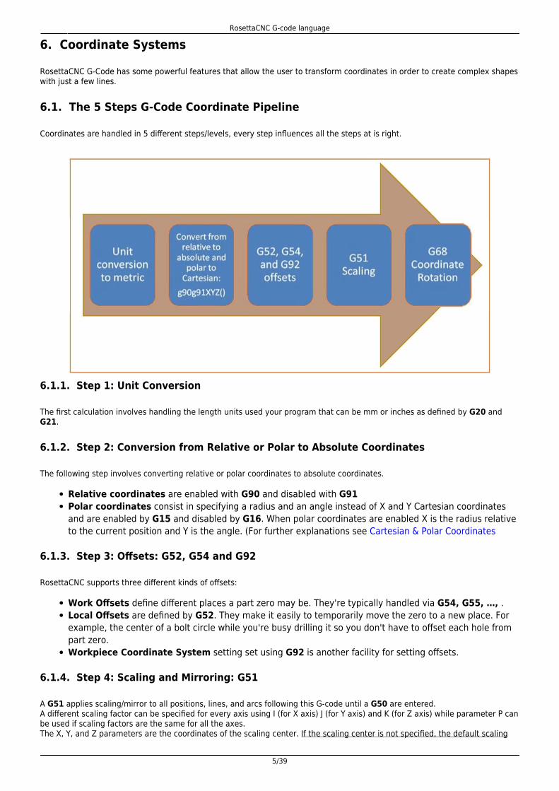
6. Coordinate Systems
RosettaCNC G-Code has some powerful features that allow the user to transform coordinates in order to create complex shapeswith just a few lines.
6.1. The 5 Steps G-Code Coordinate Pipeline
Coordinates are handled in 5 different steps/levels, every step influences all the steps at is right.
6.1.1. Step 1: Unit Conversion
The first calculation involves handling the length units used your program that can be mm or inches as defined by G20 andG21.
6.1.2. Step 2: Conversion from Relative or Polar to Absolute Coordinates
The following step involves converting relative or polar coordinates to absolute coordinates.
Relative coordinates are enabled with G90 and disabled with G91Polar coordinates consist in specifying a radius and an angle instead of X and Y Cartesian coordinatesand are enabled by G15 and disabled by G16. When polar coordinates are enabled X is the radius relativeto the current position and Y is the angle. (For further explanations see Cartesian & Polar Coordinates
6.1.3. Step 3: Offsets: G52, G54 and G92
RosettaCNC supports three different kinds of offsets:
Work Offsets define different places a part zero may be. They're typically handled via G54, G55, …, .Local Offsets are defined by G52. They make it easily to temporarily move the zero to a new place. Forexample, the center of a bolt circle while you're busy drilling it so you don't have to offset each hole frompart zero.Workpiece Coordinate System setting set using G92 is another facility for setting offsets.
6.1.4. Step 4: Scaling and Mirroring: G51
A G51 applies scaling/mirror to all positions, lines, and arcs following this G-code until a G50 are entered.A different scaling factor can be specified for every axis using I (for X axis) J (for Y axis) and K (for Z axis) while parameter P canbe used if scaling factors are the same for all the axes.The X, Y, and Z parameters are the coordinates of the scaling center. If the scaling center is not specified, the default scaling

RosettaCNC G-code language
6/39
center is the current cutter position (not the current origin).To mirror, enter a negative value for the scaling factor.
Notes:
If the arc radius was specified with R, the radius will be scaled by the larger of the two circular plane scalefactors. The result will be a circular arc between the scaled arc start and the scaled arc end.If the arc center was specified with I, J, and/or K, the centres will be scaled by the appropriate axis scalefactors. The result will be a circular arc from the scaled arc start, around the scaled center, and usuallywith a line from the end of the circular arc to the scaled arc end.In no case can an ellipse be generated using scaling.
( © 2019 RosettaCNC Motion )( file name: scaling.ngc )( G-code scaling example that uses G50 and G51 ) G21 G40 G49 G90 G54 G50 G69 M98 P1 ; Normal windowG0 X0 Y0G59G0 G90 x0 y0 z0G51 P2 ; Scaling center is X0 Y0 Z0M98 P1 ; Scaled windowG50 ; Move to the right using G55 system to avoid plot overlappingG10 L2 P2 x40G55 G0 G90 x0 y0 z0M98 P1 ; Normal windowG51 X15 Y15 P2 ;M98 P1 ; Scaled windowG50 G10 L2 P2 x0G54 ; Move to the right using G55 system to avoid plot overlappingG10 L2 P3 x80G56 G0 G90 x0 y0 z0M98 P1 ; Normal windowG51 X10 Y10 P2 ;M98 P1 ; Scaled windowG50 G10 L2 P3 x0G54M2 ( Gothic window )O1 F20. S500 ; G00 X10 Y10 G01 X20 Y20 G03 X10 R5 ;or I-5 J0 G01 Y10
RosettaCNC G-code language
7/39
G00 X0 Y0M99
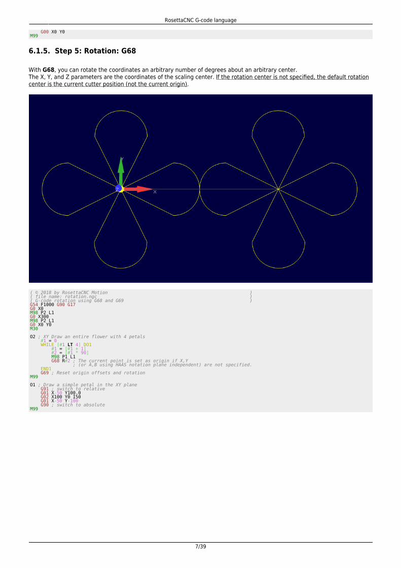
6.1.5. Step 5: Rotation: G68
With G68, you can rotate the coordinates an arbitrary number of degrees about an arbitrary center.The X, Y, and Z parameters are the coordinates of the scaling center. If the rotation center is not specified, the default rotationcenter is the current cutter position (not the current origin).
( © 2018 by RosettaCNC Motion )( file name: rotation.ngc )( G-code rotation using G68 and G69 )G54 F1000 G90 G17G0 X0M98 P2 L1G0 X300M98 P2 L1G0 X0 Y0M30 O2 ; XY Draw an entire flower with 4 petals #1 = 0 WHILE [#1 LT 4] DO1 #1 = [#1 + 1] #2 = [#1 * 90] M98 P1 L1 G68 R#2 ; The current point is set as origin if X,Y ; (or A,B using HAAS notation plane independent) are not specified. END1 G69 ; Reset origin offsets and rotationM99 O1 ; Draw a simple petal in the XY plane G91 ; switch to relative G01 X-50 Y100.0 G02 X100 Y0 I50 G01 X-50 Y-100 G90 ; switch to absoluteM99

RosettaCNC G-code language
8/39
7. Cartesian & Polar Coordinates
With Cartesian Coordinates X, Y, and Z represent distances from part zero (absolute coordinates) or from the current position(relative coordinates).
With polar coordinates, we use an angle and a distance relative to the origin.
The following picture gives a graphical overview.
7.1. Use on different planes
7.1.1. Standard syntax
XY Plane: X is used to identify the radius and Y to identify the angleYZ Plane: Y is used to identify the radius and Z to identify the angleXZ Plane: X is used to identify the radius and Z to identify the angle
Plane independent syntax
It is also possible to use a plane independent syntax using two special symbols:
@ for the radius^ for the angle
RosettaCNC G-code language
9/39
7.2. Examples
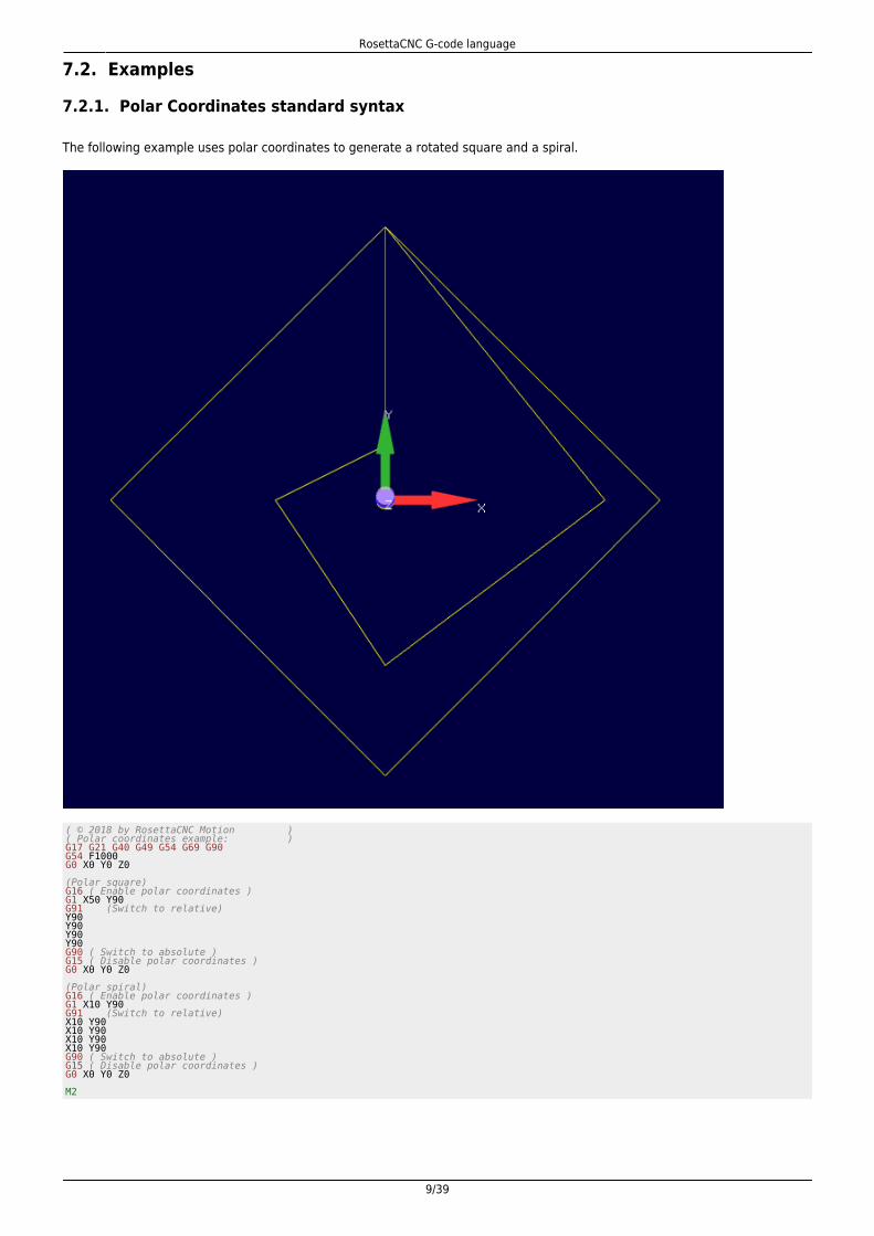
7.2.1. Polar Coordinates standard syntax
The following example uses polar coordinates to generate a rotated square and a spiral.
( © 2018 by RosettaCNC Motion )( Polar coordinates example: )G17 G21 G40 G49 G54 G69 G90G54 F1000G0 X0 Y0 Z0 (Polar square)G16 ( Enable polar coordinates )G1 X50 Y90G91 (Switch to relative)Y90Y90Y90Y90G90 ( Switch to absolute )G15 ( Disable polar coordinates )G0 X0 Y0 Z0 (Polar spiral)G16 ( Enable polar coordinates )G1 X10 Y90G91 (Switch to relative)X10 Y90X10 Y90X10 Y90X10 Y90G90 ( Switch to absolute )G15 ( Disable polar coordinates )G0 X0 Y0 Z0 M2
RosettaCNC G-code language
10/39
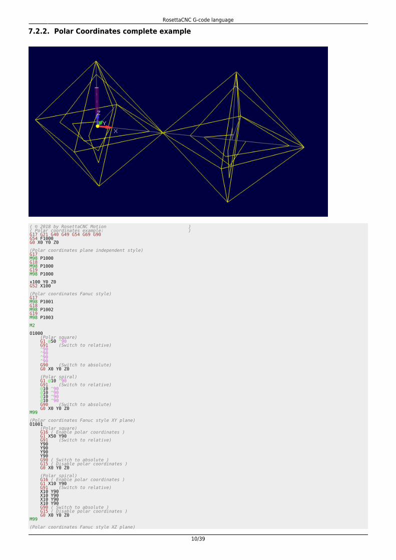
7.2.2. Polar Coordinates complete example
( © 2018 by RosettaCNC Motion )( Polar coordinates example: )G17 G21 G40 G49 G54 G69 G90G54 F1000G0 X0 Y0 Z0 (Polar coordinates plane independent style)G17M98 P1000G18M98 P1000G19M98 P1000 x100 Y0 Z0G52 X100 (Polar coordinates Fanuc style)G17M98 P1001G18M98 P1002G19M98 P1003 M2 O1000 (Polar square) G1 @50 ^90 G91 (Switch to relative) ^90 ^90 ^90 ^90 G90 (Switch to absolute) G0 X0 Y0 Z0 (Polar spiral) G1 @10 ^90 G91 (Switch to relative) @10 ^90 @10 ^90 @10 ^90 @10 ^90 G90 (Switch to absolute) G0 X0 Y0 Z0M99 (Polar coordinates Fanuc style XY plane)O1001 (Polar square) G16 ( Enable polar coordinates ) G1 X50 Y90 G91 (Switch to relative) Y90 Y90 Y90 Y90 G90 ( Switch to absolute ) G15 ( Disable polar coordinates ) G0 X0 Y0 Z0 (Polar spiral) G16 ( Enable polar coordinates ) G1 X10 Y90 G91 (Switch to relative) X10 Y90 X10 Y90 X10 Y90 X10 Y90 G90 ( Switch to absolute ) G15 ( Disable polar coordinates ) G0 X0 Y0 Z0M99 (Polar coordinates Fanuc style XZ plane)
RosettaCNC G-code language
11/39
O1002 (Polar square) G16 ( Enable polar coordinates ) G1 X50 Z90 G91 (Switch to relative) Z90 Z90 Z90 Z90 G90 ( Switch to absolute ) G15 ( Disable polar coordinates ) G0 X0 Y0 Z0 (Polar spiral) G16 ( Enable polar coordinates ) G1 X10 Z90 G91 (Switch to relative) X10 Z90 X10 Z90 X10 Z90 X10 Z90 G90 ( Switch to absolute ) G15 ( Disable polar coordinates ) G0 X0 Y0 Z0M99 (Polar coordinates Fanuc style YZ plane)O1003 (Polar square) G16 ( Enable polar coordinates ) G1 Y50 Z90 G91 (Switch to relative) Z90 Z90 Z90 Z90 G90 ( Switch to absolute ) G15 ( Disable polar coordinates ) G0 X0 Y0 Z0 (Polar spiral) G16 ( Enable polar coordinates ) G1 Y10 Z90 G91 (Switch to relative) Y10 Z90 Y10 Z90 Y10 Z90 Y10 Z90 G90 ( Switch to absolute ) G15 ( Disable polar coordinates ) G0 X0 Y0 Z0M99
RosettaCNC G-code language
12/39
8. Arcs & Helices
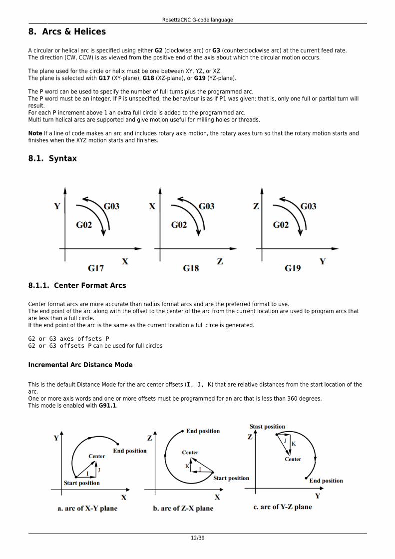
A circular or helical arc is specified using either G2 (clockwise arc) or G3 (counterclockwise arc) at the current feed rate.The direction (CW, CCW) is as viewed from the positive end of the axis about which the circular motion occurs.
The plane used for the circle or helix must be one between XY, YZ, or XZ.The plane is selected with G17 (XY-plane), G18 (XZ-plane), or G19 (YZ-plane).
The P word can be used to specify the number of full turns plus the programmed arc.The P word must be an integer. If P is unspecified, the behaviour is as if P1 was given: that is, only one full or partial turn willresult.For each P increment above 1 an extra full circle is added to the programmed arc.Multi turn helical arcs are supported and give motion useful for milling holes or threads.
Note If a line of code makes an arc and includes rotary axis motion, the rotary axes turn so that the rotary motion starts andfinishes when the XYZ motion starts and finishes.
8.1. Syntax
8.1.1. Center Format Arcs
Center format arcs are more accurate than radius format arcs and are the preferred format to use.The end point of the arc along with the offset to the center of the arc from the current location are used to program arcs thatare less than a full circle.If the end point of the arc is the same as the current location a full circe is generated.
G2 or G3 axes offsets PG2 or G3 offsets P can be used for full circles
Incremental Arc Distance Mode
This is the default Distance Mode for the arc center offsets (I, J, K) that are relative distances from the start location of thearc.One or more axis words and one or more offsets must be programmed for an arc that is less than 360 degrees.This mode is enabled with G91.1.
RosettaCNC G-code language
13/39
Absolute Arc Distance Mode
Arc center offsets (I, J, K) are relative distances from the current origin of the axes.One or more axis words and both offsets must be programmed for arcs less than 360 degrees.This mode is enabled with G90.1.
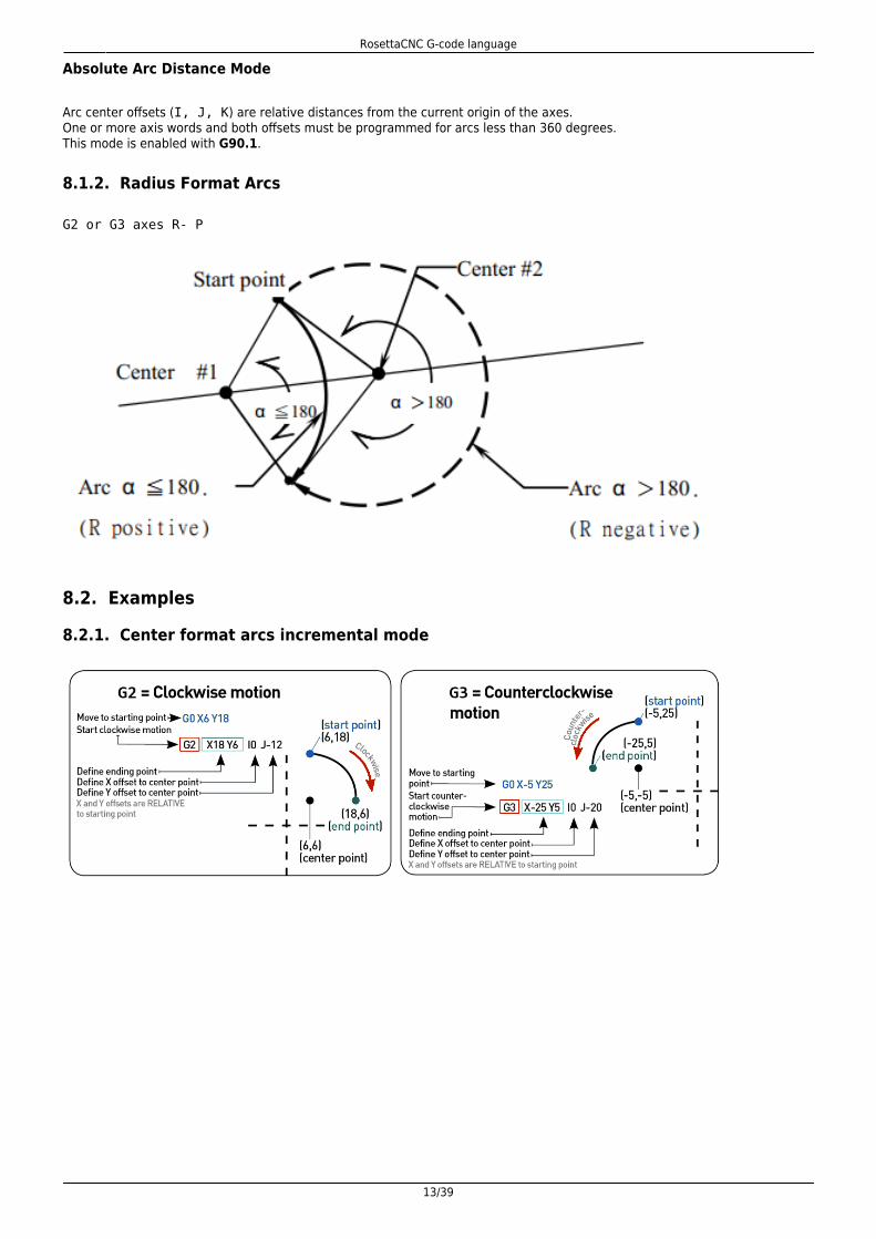
8.1.2. Radius Format Arcs
G2 or G3 axes R- P
8.2. Examples
8.2.1. Center format arcs incremental mode
RosettaCNC G-code language
14/39
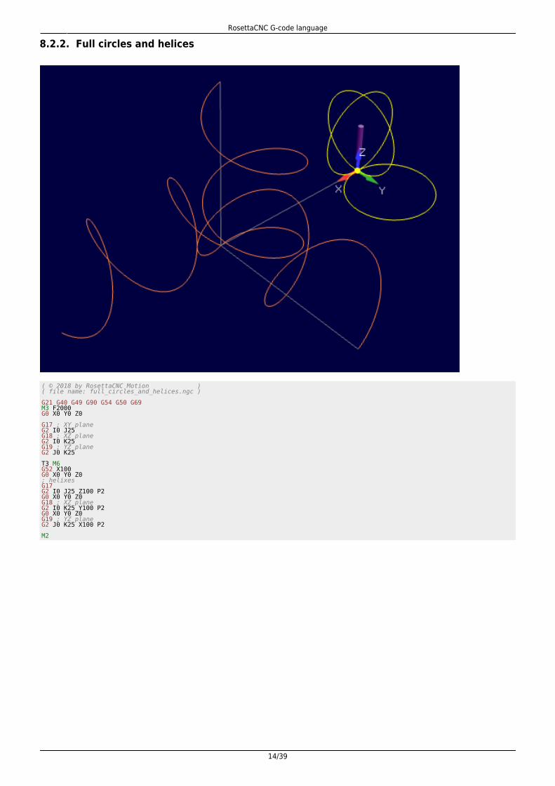
8.2.2. Full circles and helices
( © 2018 by RosettaCNC Motion )( file name: full_circles_and_helices.ngc ) G21 G40 G49 G90 G54 G50 G69M3 F2000G0 X0 Y0 Z0 G17 ; XY planeG2 I0 J25G18 ; XZ planeG2 I0 K25G19 ; YZ planeG2 J0 K25 T3 M6G52 X100G0 X0 Y0 Z0; helixesG17G2 I0 J25 Z100 P2G0 X0 Y0 Z0G18 ; XZ planeG2 I0 K25 Y100 P2G0 X0 Y0 Z0G19 ; YZ planeG2 J0 K25 X100 P2 M2

RosettaCNC G-code language
15/39
9. Motion Control Modes
RosettaCNC supports three different motion control modes:
Exact path mode enabled with G61 that forces the CNC to follow the programmed path using the lookahead feature to diminish program duration.Exact stop mode enabled with G61.1 that forces the CNC to stop at the end of every motion block.Continuous path mode enabled with G64 that enable both look ahead feature and trajectoryblending feature to reach maximum speed performances.This mode supports two optional parameters
P: Trajectory deformation/blending toleranceQ: Points removal threshold that can be used to decrease the number of points generated by the CAM
9.1. Examples
Exact stop one shot example
RosettaCNC supports G9 command to force exact stop at the end of a specific block.
( © 2018 by RosettaCNC Motion )( G9 example: Exact stop one shot ) G54 G64 P5.0 F5000G0 X-10 Y-10 Z0G1 X0 Y0G9X40Y40G9X10Y0 ( The same result could be achieved using G61.1)G0 X-10 Y-60G92 X-10 Y-10G1 X0 Y0G61.1X40G64Y40G61.1X10G64Y0G92.1M30
RosettaCNC G-code language
16/39
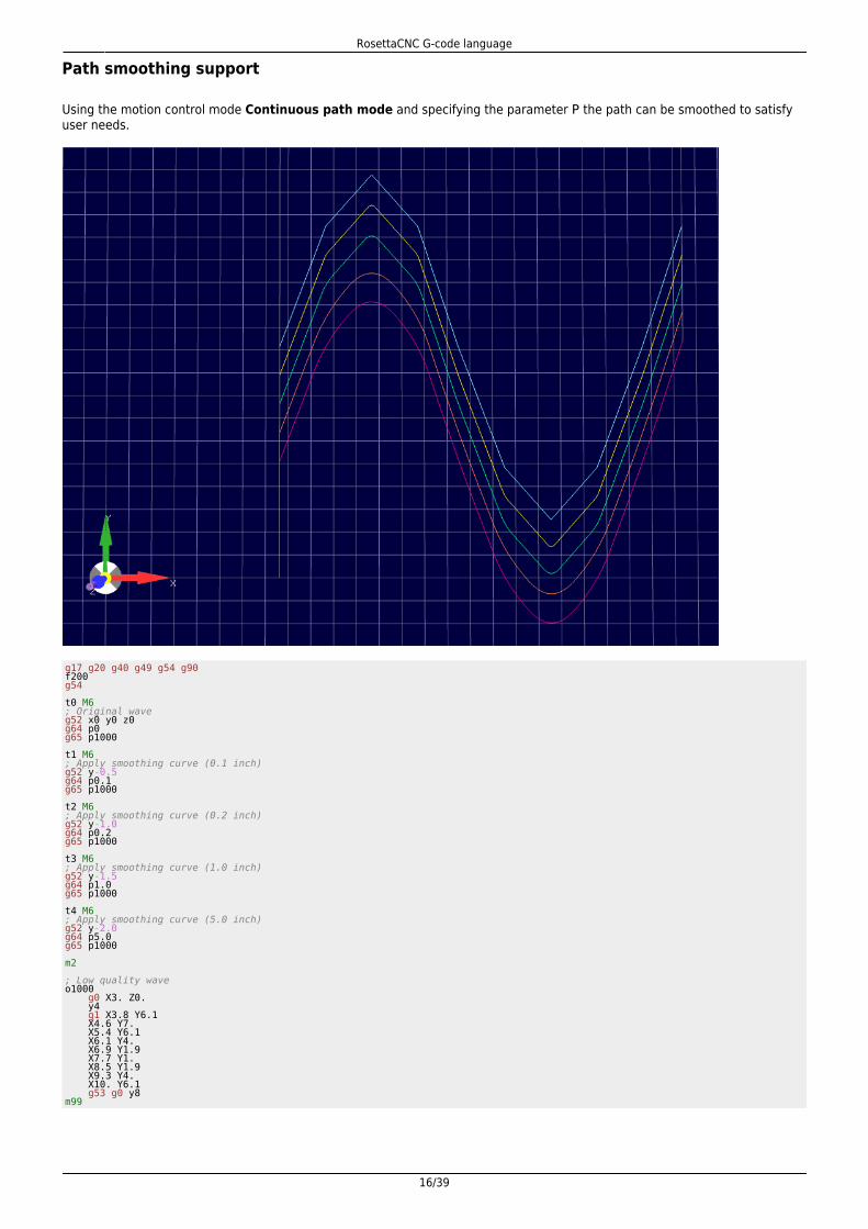
Path smoothing support
Using the motion control mode Continuous path mode and specifying the parameter P the path can be smoothed to satisfyuser needs.
g17 g20 g40 g49 g54 g90f200g54 t0 M6; Original waveg52 x0 y0 z0g64 p0g65 p1000 t1 M6; Apply smoothing curve (0.1 inch)g52 y-0.5g64 p0.1g65 p1000 t2 M6; Apply smoothing curve (0.2 inch)g52 y-1.0g64 p0.2g65 p1000 t3 M6; Apply smoothing curve (1.0 inch)g52 y-1.5g64 p1.0g65 p1000 t4 M6; Apply smoothing curve (5.0 inch)g52 y-2.0g64 p5.0g65 p1000 m2 ; Low quality waveo1000 g0 X3. Z0. y4 g1 X3.8 Y6.1 X4.6 Y7. X5.4 Y6.1 X6.1 Y4. X6.9 Y1.9 X7.7 Y1. X8.5 Y1.9 X9.3 Y4. X10. Y6.1 g53 g0 y8m99

RosettaCNC G-code language
17/39
10. Go to predefined positions
10.1. G28 and G28.1
G28 uses the values stored in parameters 5161-5166 as the X Y Z A B C final point to move to.The parameter values are absolute machine coordinates
G28 - makes a rapid move from the current position to the absolute position of the values in parameters5161-5166. Since the position stored in the parameters 5161-5166 is considered absolute the tool offsetenabled with G43 influences the position. Example: #5163 = 0, tool_offset_z = 50 → target_position =#5163 - tool_offset_z = -50.G28 axes - makes a rapid move to the position specified by axes including any offsets, then will make arapid move to the absolute position of the values in parameters 5161-5166 for axes specified.Any axis not specified will not move.G28.1 - stores the current absolute position into parameters 5161-5166.
Examples
G28 (rapid move to the values specified into the stored parameters, moving all axes)G28 Z10.0 (rapid move to Z10.0 then to location specified in the G28 stored parameters, moving only Z)G28 G91 Z0 (rapid relative move to relative Z0.0 then to location specified in the G28 stored parameters, moving only Z)
The last example skip the intermediate position, since the movement is relative and with a displacement of 0.It is usually used to ensure that only axis Z will move to the homing position specified in G28 parameters.
10.2. G30 and G30.1
G30 uses the values stored in parameters 5181-5186 as the X Y Z A B C final point to move to.The parameter values are absolute machine coordinates
G30 - makes a rapid move from the current position to the absolute position of the values in parameters5181-5186.G30 axes - makes a rapid move to the position specified by axes including any offsets, then will make arapid move to the absolute position of the values in parameters 5181-5186 for axes specified.Any axis not specified will not move.G30.1 - stores the current absolute position into parameters 5181-5186.
10.3. Examples

RosettaCNC G-code language
18/39
( © 2018 by RosettaCNC Motion )( file name: g28_example.ngc ) G17 G21 G40 G49 G50 G54 G69 G90 #5161=20 ( G28 X )#5162=40 ( G28 Y )#5163=20 ( G28 Z ) G52 X20 Y20G28 G91 Z0M98 P1000; Since Z axis is specified only axis Z will be moved to the; position stored in parameter 5163.; Since the intermediate point Z0 is specified with G91 the; intermediate point position will be skipped.G28 G91 Z0G90 G52 X50 Y50M98 P1000; If no axis is specified with the G28 the position stored in; the parameters 5161-5166 is used.G28 M2 ( Square )O1000 G90 G0 X0 Y0 Z0 G1 X10 Y10 X0 Y0M99
RosettaCNC G-code language
19/39
11. G Code Order of Execution
The order of execution of items on a line is defined not by the position of each item on the line, but by the following list:
the entire line is skipped if it starts with a forward slash / and the block delete toggle is activecomments started with ( or ;if N is the first letter of a line the following number is interpreted as line numberwhen a subroutine declaration is found (example O1001) the remaining part of the line is allowed only tobe a comment.control flow statements like WHILE,IFset feed rate mode G93, G94set feed rate Fset spindle speed SI/O handling: M62, M63, M66change tool: M6 if user tool change macro is disabled, M61, M106spindle on or off: M3, M4, M5coolant on or off: M7, M8, M9, M17, M18M48, M49M109, M120dwell G4set active plane: G17, G18, G19set length units: G20, G21cutter radius compensation on or off: G40, G41, G42cutter length compensation on or off: G43, G49coordinate system selection: G54, G55, G56, G57, G58, G59, G59.1, G59.2, G59.3set path control mode: G61, G61.1, G64set distance mode: G90, G91set arc mode: G90.1, G91.1set retract mode: G98, G99non modal G-codes: G10, G28, G28.1, G30, G30.1, G52, G92, G92.1, G92.2, G92.3scaling: G50, G51rotation: G68, G69motion: G0, G1, G2, G3, G9, G76, G80stop: M0, M1, M2, M30, M47control flow statements like GOTOsubroutines and macros: M98, M6 only if user tool change macro is enabled
Some codes require to be the only G/M codes in the line, they are: G65, G100, user defined m codes and user defined g codes

RosettaCNC G-code language
20/39
12. Cutter compensation
The cutter radius compensation capabilities of the Interpreter enable the programmer to specify that a cutter should travel tothe right or left of an open or closed contour composed of arcs of circles and straight line segments, all planes are supportedXY, YZ and XZ.
12.1. G41, G42 Cutter Compensation
G41 <D> <I> left of programmed pathG42 <D> <I> right of programmed path
Notes
D - tool numberI - dynamic radius offsetThe D word is optional; if there is no D word the radius of the currently loaded tool will be used (if no tool isloaded and no D word is given, a radius of 0 will be used).The I word is optional; if there is I word the resulting radius will be: “table diameter value” / 2 - “I value”.If supplied, the D word is the tool number to use. This would normally be the number of the tool in thespindle (in which case the D word is redundant and need not be supplied), but it may be any valid toolnumber.It is an error if:
The D number is not a valid tool number or 0.Cutter compensation is commanded to turn on when it is already on.
12.2. G41.1, G42.1 Dynamic Cutter Compensation
G41.1 D <L> (left of programmed path)G42.1 D <L> (right of programmed path)
Notes
D - cutter diameterL - tool orientation (see lathe tool orientation)
G41.1 & G42.1 function the same as G41 & G42 with the added scope of being able to program the tooldiameter. The L word defaults to 0 if unspecified.
It is an error if:The YZ plane is active.
RosettaCNC G-code language
21/39
The L number is not in the range from 0 to 9 inclusive.The L number is used when the XZ plane is not active.Cutter compensation is commanded to turn on when it is already on.
12.3. Tool compensation entry options
Two compensation entry option are supported:
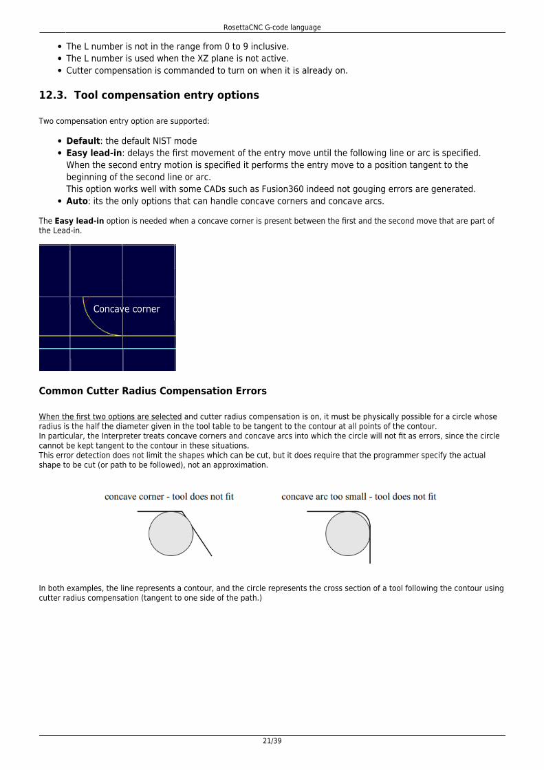
Default: the default NIST modeEasy lead-in: delays the first movement of the entry move until the following line or arc is specified.When the second entry motion is specified it performs the entry move to a position tangent to thebeginning of the second line or arc.This option works well with some CADs such as Fusion360 indeed not gouging errors are generated.Auto: its the only options that can handle concave corners and concave arcs.
The Easy lead-in option is needed when a concave corner is present between the first and the second move that are part ofthe Lead-in.
Common Cutter Radius Compensation Errors
When the first two options are selected and cutter radius compensation is on, it must be physically possible for a circle whoseradius is the half the diameter given in the tool table to be tangent to the contour at all points of the contour.In particular, the Interpreter treats concave corners and concave arcs into which the circle will not fit as errors, since the circlecannot be kept tangent to the contour in these situations.This error detection does not limit the shapes which can be cut, but it does require that the programmer specify the actualshape to be cut (or path to be followed), not an approximation.
In both examples, the line represents a contour, and the circle represents the cross section of a tool following the contour usingcutter radius compensation (tangent to one side of the path.)
RosettaCNC G-code language
22/39
12.4. Examples
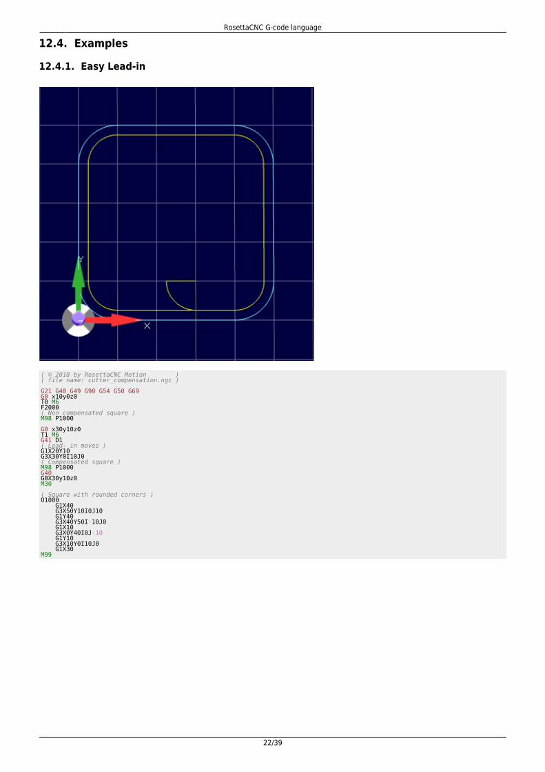
12.4.1. Easy Lead-in
( © 2018 by RosettaCNC Motion )( file name: cutter_compensation.ngc ) G21 G40 G49 G90 G54 G50 G69G0 x10y0z0T0 M6F2000( Non compensated square )M98 P1000 G0 x30y10z0T1 M6G41 D1( Lead- in moves )G1X20Y10G3X30Y0I10J0( Compensated square )M98 P1000G40G0X30y10z0M30 ( Square with rounded corners )O1000 G1X40 G3X50Y10I0J10 G1Y40 G3X40Y50I-10J0 G1X10 G3X0Y40I0J-10 G1Y10 G3X10Y0I10J0 G1X30M99

RosettaCNC G-code language
23/39
12.4.2. Auto
( © 2018 by RosettaCNC Motion )( file name: automatic_compensation.ngc )( G-code with cutter comensation example in all planes )( Note: for a real work the cutter compensation lead-in )( move should be added manually. )G17 G21 G40 G49 G90 G54 G50 G69 ; XY planeG17G00 Z50G00 X50 Y50 M6 T0F1000. S500G00 Z10M98 P1 ; Normal window G00 X50 Y50M6 T3F1000. S500G01 Z10G41M98 P1 ; Compensated windowG40 G52 X150G00 X0 Y0 Z0 ; XZ PlaneG18G00 Y50G00 Z50 X50 M6 T0G00 Y10M98 P2 ; Normal window G00 Z50 X50M6 T3F1000. S500G01 Y10G41M98 P2 ; Compensated windowG40 G52 X-150G00 X0 Y0 Z0 ; YZ PlaneG19
RosettaCNC G-code language
24/39
G00 X50G00 Y50 Z50 M6 T0G00 X10M98 P3 ; Normal window G00 Y50 Z50M6 T3F1000. S500G01 X10G41M98 P3 ; Compensated windowG40 M2 O1 ; Gothic window XY G91 G01 Y-50 X50 Y100 G03 X-100 R50 G01 Y-100 X50 G90M99 O2 ; Gothic window XZ G91 G01 X-50 Z50 X100 G03 Z-100 R50 G01 X-100 Z50 G90M99 O3 ; Gothic window YZ G91 G01 Z-50 Y50 Z100 G03 Y-100 R50 G01 Z-100 Y50 G90M99

RosettaCNC G-code language
25/39
13. Macro programming
Rosetta CNC supports Macro programming (following Fanuc Macro B style).
Your G-code programs or sub-programs can include a few non G-code commands that use:
VariablesArithmetic Logic & StatementsSubroutinesCustom Macro calls (subroutines with arguments)Looping & Branching
Subroutines, Macros and WHILE statements can be nested up to 100 times.
The following example provide an overview of the supported macro programming features.
F5000G0 x0 y0 z0G1 x100 ( RosettaCnC supports G-code subroutines )( To invoke a subroutine type "M98 P<subroutine id> L<repetitions>". )( The following line invoke the subroutine with id 1 for 2 times. )M98 P1 L2 ( RosettaCnC supports G-code numbered external subroutines )M98 P101 L2 ( RosettaCnC supports G-code named external subroutines )M98 P"named_sub.ngc" L2 #1 = 10#2 = 20#3 = 30#4 = -10( RosettaCnC supports macro calls )( The arguments are loaded in the correspondent parameters. )( When the call is finished the parameters 1-33 are restored to the value )( they had before the call . ); A = #1; B = #2; C = #3G65 P2 A3 B5 C2 IF [#4 EQ -10] THEN M109 P"Parameter 4 is restored to #4 when the macro is finished" G65 P"named_sub.ngc" A3 B5 C2 ( RosettaCnC supports user defined M codes with arguments [M200 - M299] )M200 A10 B5 C7.0 m2 ( Program End) ( RosettaCnC supports G-code subroutines, in the following lines two )( subroutines are defined. ) ( The following lines declare a subrutine with id 1 )O1( Subroutine body that contains G-code instructions )G0 x0 y0 z0G0 x0 y0 z50G0 x0 y0 z0( The following line define the end of the subroutine )M99 O2( Subroutine body can access and modify local parameters )#4 = [[#1 + #2] * #3] IF [#5 EQ #0] THEN M109 P"Parameter 5 has not been set when the macro has been called" IF [#4 EQ 16] THEN M109 P"Parameter 4 is equal to #4"( The following line define the end of the subroutine )M99
RosettaCNC G-code language
26/39
14. G-code variables
Rosetta CNC supports Macro programming (following Fanuc Macro B style). Your G-code programs or sub-programs caninclude a few non G-code commands that use variables, arithmetic, logic statements, and looping are available.
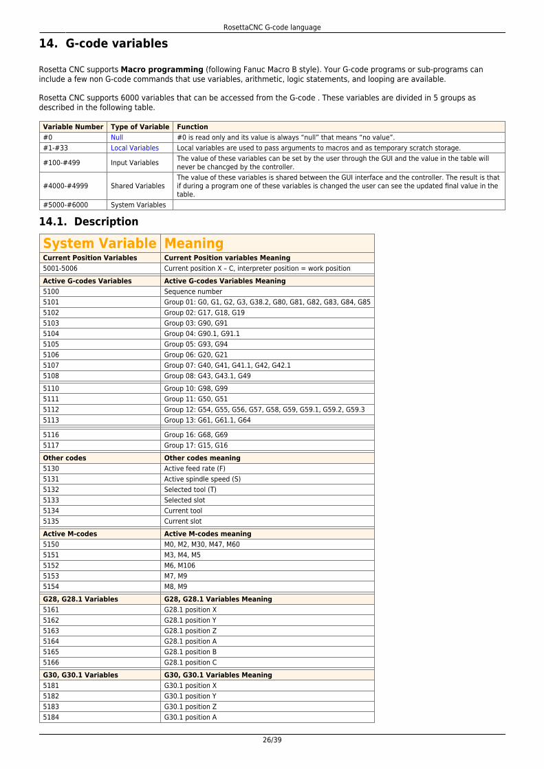
Rosetta CNC supports 6000 variables that can be accessed from the G-code . These variables are divided in 5 groups asdescribed in the following table.
Variable Number Type of Variable Function#0 Null #0 is read only and its value is always “null” that means “no value”.#1-#33 Local Variables Local variables are used to pass arguments to macros and as temporary scratch storage.
#100-#499 Input Variables The value of these variables can be set by the user through the GUI and the value in the table willnever be chancged by the controller.
#4000-#4999 Shared VariablesThe value of these variables is shared between the GUI interface and the controller. The result is thatif during a program one of these variables is changed the user can see the updated final value in thetable.
#5000-#6000 System Variables
14.1. Description
System Variable MeaningCurrent Position Variables Current Position variables Meaning5001-5006 Current position X – C, interpreter position = work positionActive G-codes Variables Active G-codes Variables Meaning5100 Sequence number5101 Group 01: G0, G1, G2, G3, G38.2, G80, G81, G82, G83, G84, G855102 Group 02: G17, G18, G195103 Group 03: G90, G915104 Group 04: G90.1, G91.15105 Group 05: G93, G945106 Group 06: G20, G215107 Group 07: G40, G41, G41.1, G42, G42.15108 Group 08: G43, G43.1, G495110 Group 10: G98, G995111 Group 11: G50, G515112 Group 12: G54, G55, G56, G57, G58, G59, G59.1, G59.2, G59.35113 Group 13: G61, G61.1, G64
5116 Group 16: G68, G695117 Group 17: G15, G16Other codes Other codes meaning5130 Active feed rate (F)5131 Active spindle speed (S)5132 Selected tool (T)5133 Selected slot5134 Current tool5135 Current slotActive M-codes Active M-codes meaning5150 M0, M2, M30, M47, M605151 M3, M4, M55152 M6, M1065153 M7, M95154 M8, M9G28, G28.1 Variables G28, G28.1 Variables Meaning5161 G28.1 position X5162 G28.1 position Y5163 G28.1 position Z5164 G28.1 position A5165 G28.1 position B5166 G28.1 position CG30, G30.1 Variables G30, G30.1 Variables Meaning5181 G30.1 position X5182 G30.1 position Y5183 G30.1 position Z5184 G30.1 position A

RosettaCNC G-code language
27/39
System Variable MeaningCurrent Position Variables Current Position variables Meaning5185 G30.1 position B5186 G30.1 position CWCS Offsets Variables WCS Offsets Variables Meaning5211 - 5216 G92 offset X - CWCS Variables WCS Variables Meaning5220 Coord. System number5221 - 5226 Coord. System 1 X – C5241 - 5246 Coord. System 2 X – C5261 - 5266 Coord. System 3 X – C5281 - 5286 Coord. System 4 X – C5301 - 5306 Coord. System 5 X – C5321 - 5326 Coord. System 6 X – C5341 - 5346 Coord. System 7 X – C5361 - 5366 Coord. System 8 X – C5381 - 5386 Coord. System 9 X – CReturn Variables Return Variables Meaning5398 Return value for M665399 Return value for M109 and M120Tool Variables Tool Variables Meaning5400 Current tool id5402 Current tool offset X5403 Current tool offset Y5404 Current tool offset Z5410 Current tool diameter5420 Tool compensation offset X (Set using G43, G43.1, G43.2, G49)5421 Tool compensation offset Y (Set using G43, G43.1, G43.2, G49)5422 Tool compensation offset Z (Set using G43, G43.1, G43.2, G49)5426 The id of the tool used for RTCP compensation (G43.4)
14.2. Vacant or Empty Variables
In many cases, a variable may also be undefined. In this case, the variable is set to #0, which identifies a null variable (empty /not initialized). Indeed #0 is a read-only variable used mainly for two purposes:
check if a variable has been initializedreset a variable
At the beginning of the compilation every non system variable is set to #0.
A null variable has no value, it should not be confused with a variable that has a zero value.
#101 = 0 ; Variable #101 has a zero value#102 = #0 ; Variable #102 is vacant (empty), has no value and cannot be used for some operations
The following piece of G-code provide an example of the operations that can be used with an empty variable
( © 2018 by RosettaCNC Motion )( NULL paramater handling example: )( Every parameter is set to NULL when not initialized )( Parameter #0 stores the value NULL and cannot be written ) ; Comparing a null to a null variable:; Define #1 as null (that means that is is empty/not initialized)#1 = #0IF[#1 EQ #0] THEN M109 P"IF[#1 EQ #0] Should return TRUE"IF[#1 NE #0] THEN M109 P"IF[#1 NE #0] Should return FALSE"IF[#1 GT #0] THEN M109 P"IF[#1 GT #0] Should return FALSE"IF[#1 GE #0] THEN M109 P"IF[#1 GE #0] Should return TRUE"IF[#1 LT #0] THEN M109 P"IF[#1 LT #0] Should return FALSE"IF[#1 LE #0] THEN M109 P"IF[#1 LE #0] Should return TRUE" ; Comparing a zero to a null variable:; Define #1 as zero that means #1 is equal to 0#1 = 0IF[#1 EQ #0] THEN M109 P"IF[#1 EQ #0] Should return FALSE"IF[#1 NE #0] THEN M109 P"IF[#1 NE #0] Should return TRUE"IF[#1 GT #0] THEN M109 P"IF[#1 GT #0] Should return FALSE"IF[#1 GE #0] THEN M109 P"IF[#1 GE #0] Should return TRUE"IF[#1 LT #0] THEN M109 P"IF[#1 LT #0] Should return FALSE"IF[#1 LE #0] THEN M109 P"IF[#1 LE #0] Should return TRUE" ; Comparing a null variable to a zero:; #1 is defined as null (that means #1 is vacant)#1 = #0IF[#1 EQ 0] THEN M109 P"IF[#1 EQ 0] Should return FALSE"IF[#1 NE 0] THEN M109 P"IF[#1 NE 0] Should return TRUE"IF[#1 GT 0] THEN M109 P"IF[#1 GT 0] Should return FALSE"
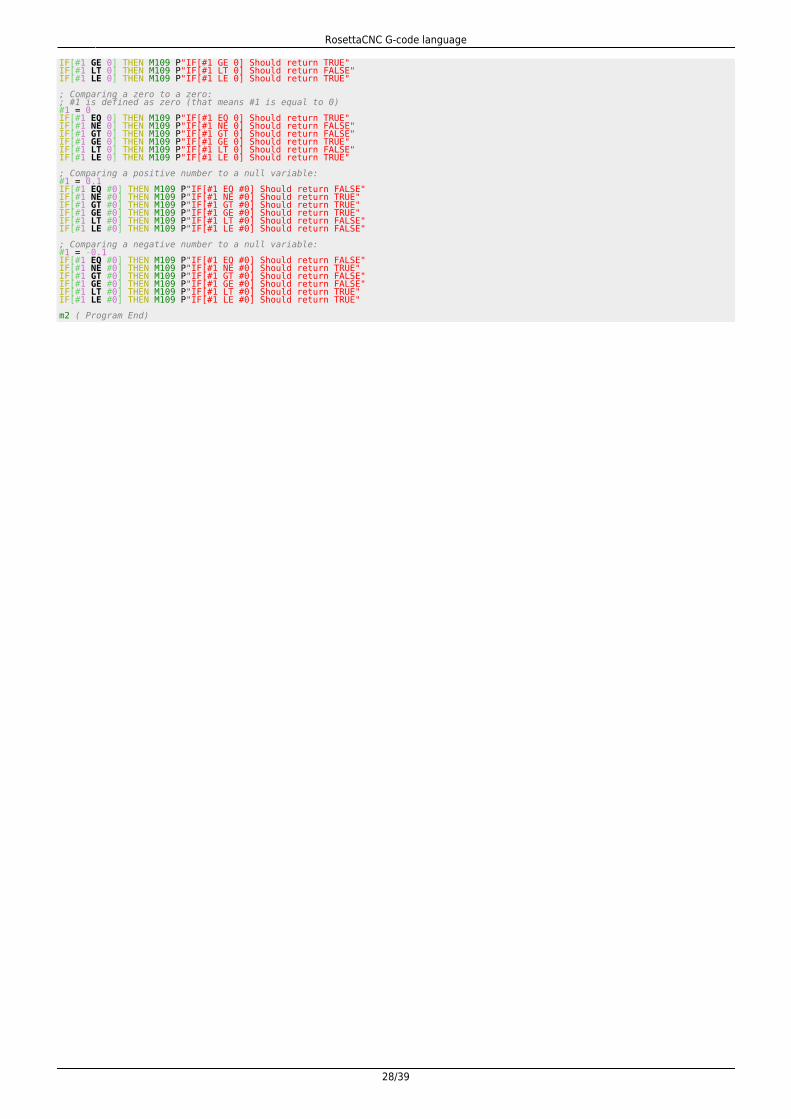
RosettaCNC G-code language
28/39
IF[#1 GE 0] THEN M109 P"IF[#1 GE 0] Should return TRUE"IF[#1 LT 0] THEN M109 P"IF[#1 LT 0] Should return FALSE"IF[#1 LE 0] THEN M109 P"IF[#1 LE 0] Should return TRUE" ; Comparing a zero to a zero:; #1 is defined as zero (that means #1 is equal to 0)#1 = 0IF[#1 EQ 0] THEN M109 P"IF[#1 EQ 0] Should return TRUE"IF[#1 NE 0] THEN M109 P"IF[#1 NE 0] Should return FALSE"IF[#1 GT 0] THEN M109 P"IF[#1 GT 0] Should return FALSE"IF[#1 GE 0] THEN M109 P"IF[#1 GE 0] Should return TRUE"IF[#1 LT 0] THEN M109 P"IF[#1 LT 0] Should return FALSE"IF[#1 LE 0] THEN M109 P"IF[#1 LE 0] Should return TRUE" ; Comparing a positive number to a null variable:#1 = 0.1IF[#1 EQ #0] THEN M109 P"IF[#1 EQ #0] Should return FALSE"IF[#1 NE #0] THEN M109 P"IF[#1 NE #0] Should return TRUE"IF[#1 GT #0] THEN M109 P"IF[#1 GT #0] Should return TRUE"IF[#1 GE #0] THEN M109 P"IF[#1 GE #0] Should return TRUE"IF[#1 LT #0] THEN M109 P"IF[#1 LT #0] Should return FALSE"IF[#1 LE #0] THEN M109 P"IF[#1 LE #0] Should return FALSE" ; Comparing a negative number to a null variable:#1 = -0.1IF[#1 EQ #0] THEN M109 P"IF[#1 EQ #0] Should return FALSE"IF[#1 NE #0] THEN M109 P"IF[#1 NE #0] Should return TRUE"IF[#1 GT #0] THEN M109 P"IF[#1 GT #0] Should return FALSE"IF[#1 GE #0] THEN M109 P"IF[#1 GE #0] Should return FALSE"IF[#1 LT #0] THEN M109 P"IF[#1 LT #0] Should return TRUE"IF[#1 LE #0] THEN M109 P"IF[#1 LE #0] Should return TRUE" m2 ( Program End)
RosettaCNC G-code language
29/39
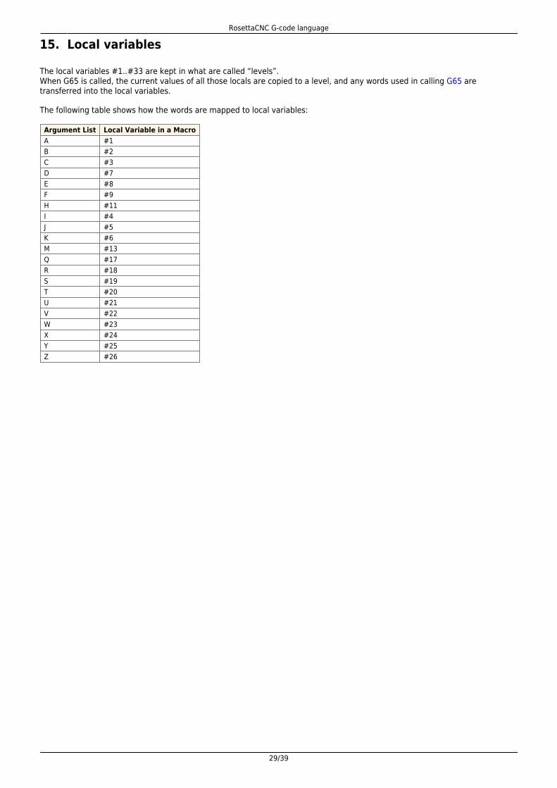
15. Local variables
The local variables #1..#33 are kept in what are called “levels”.When G65 is called, the current values of all those locals are copied to a level, and any words used in calling G65 aretransferred into the local variables.
The following table shows how the words are mapped to local variables:
Argument List Local Variable in a MacroA #1B #2C #3D #7E #8F #9H #11I #4J #5K #6M #13Q #17R #18S #19T #20U #21V #22W #23X #24Y #25Z #26

RosettaCNC G-code language
30/39
16. Arithmetic Logic & Statements
16.1. Binary Operators
Binary operators only appear inside expressions.
There are:
Mathematical operations: addition (+), subtraction (-), multiplication (*), and division (/), modulusoperation (MOD) and power operation (* *)Logical operations: non-exclusive or (OR), exclusive or (XOR), and logical and (AND)Relational operators: equality (EQ), inequality (NE), strictly greater than (GT), greater than or equal to(GE), strictly less than (LT), and less than or equal to (LE)
Their precedence is defined accordingly to the following table
Operators Precedence* * highest* / MOD+ -EQ NE GT GE LT LEAND OR XOR lowest
About equality and floating-point values
The RS274/NGC language only supports floating-point values of finite precision. The interpreter considers values equal if theirabsolute difference is less than 0.0001.
16.2. Functions
The following table shows the available functions. Unary operations arguments which take angle measures (COS, SIN, and TAN) are in degrees. Values returned by unary operations which return angle measures (ACOS, ASIN, and ATAN) are also indegrees.
Function Name ResultATAN[arg]/[arg] Four quadrant inverse tangentABS[arg] Absolute valueACOS[arg] Inverse cosineASIN[arg] Inverse sineCOS[arg] CosineEXP[arg] e raised to the given powerFIX[arg] Round down to integerFUP[arg] Round up to integerROUND[arg] Round to nearest integerLN[arg] Base-e logarithmSIN[arg] SineSQRT[arg] Square RootTAN[arg] Tangent

RosettaCNC G-code language
31/39
17. Looping & Branching
17.1. Unconditional Branching GOTOn
17.2. Conditional Branching IF [ CONDITION IS TRUE ] GOTOn
IF [#7 LT 0] GOTO65 ;If the value of variable #7 is less than 0, branch to block N65...... ;If the above condition is true, bypass this section and go down till N65...N65 ... ;Target block of the IF conditional statement
17.3. IF-THEN Option IF [ condition is true ] THEN [ argument ]
17.4. While Loop WHILE [condition] DOn
While loops can be nested as follows
WHILE [... Condition 1 is true ...] DO1 ; Start of WHILE loop 1 ... <... Body of Loop 1 - Part 1 ...> WHILE [... Condition 2 is true ...] DO2 ; Start of WHILE loop 2 ... <... Body of Loop 2 ...> ... END2 ; End of WHILE loop 2 ... <... Body of Loop 1 - Part 2 ...> ...END1 ; End of WHILE loop 1...
17.5. Example
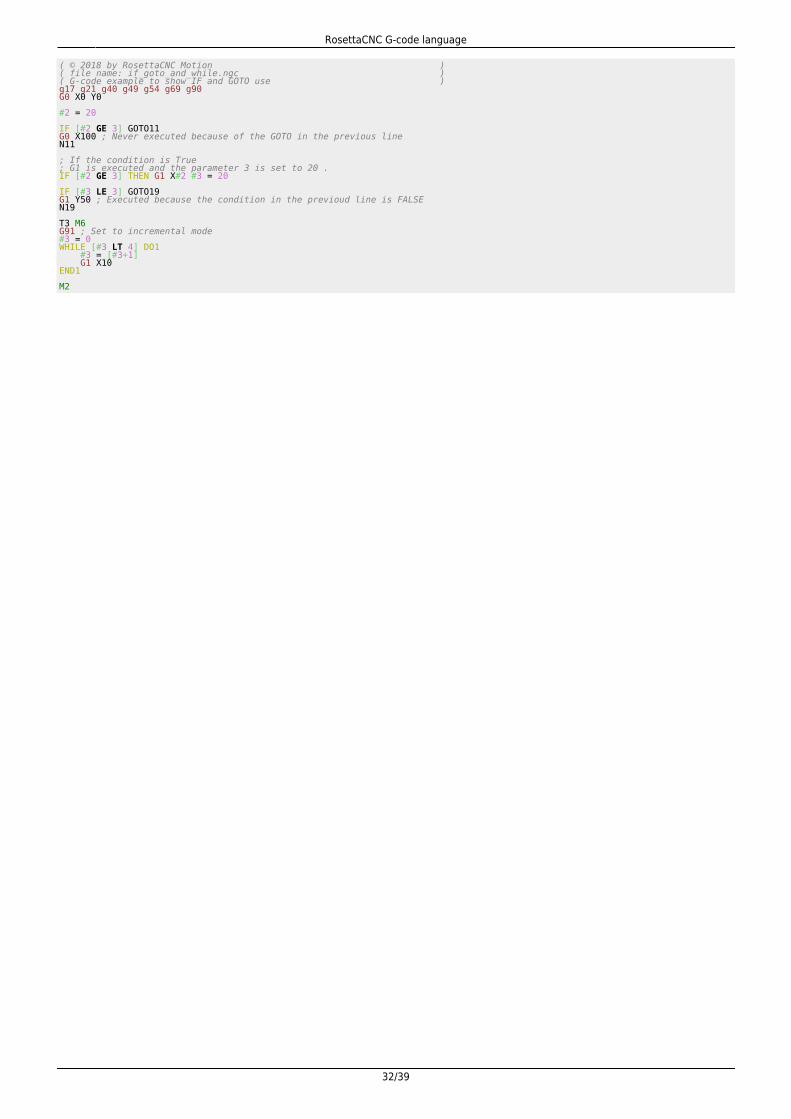
RosettaCNC G-code language
32/39
( © 2018 by RosettaCNC Motion )( file name: if_goto_and_while.ngc )( G-code example to show IF and GOTO use )g17 g21 g40 g49 g54 g69 g90G0 X0 Y0 #2 = 20 IF [#2 GE 3] GOTO11G0 X100 ; Never executed because of the GOTO in the previous lineN11 ; If the condition is True; G1 is executed and the parameter 3 is set to 20 .IF [#2 GE 3] THEN G1 X#2 #3 = 20 IF [#3 LE 3] GOTO19G1 Y50 ; Executed because the condition in the previoud line is FALSEN19 T3 M6G91 ; Set to incremental mode#3 = 0WHILE [#3 LT 4] DO1 #3 = [#3+1] G1 X10END1 M2
RosettaCNC G-code language
33/39
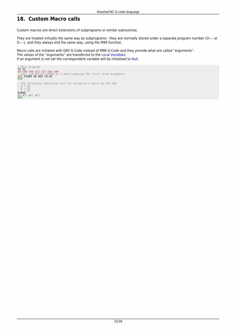
18. Custom Macro calls
Custom macros are direct extensions of subprograms or similar subroutines.
They are treated virtually the same way as subprograms - they are normally stored under a separate program number (O—- orO—–), and they always end the same way, using the M99 function.
Macro calls are initiated with G65 G-Code instead of M98 G-Code and they provide what are called “arguments”.The values of the “arguments” are transferred to the Local Variables.If an argument is not set the correspondent variable will be initialised to Null.
; Main programT5 M6G0 G90 G40 G21 G17 G94 G80; Call subroutine O1000 as a macro passing the first three argumentsG65 P1000 A0 B35 C0.01M30 ; The following subroutine will be called as a macro by the G65; A = #1; B = #2; C = #3O1000G1 x#1 y#2 z#3M99
RosettaCNC G-code language
34/39
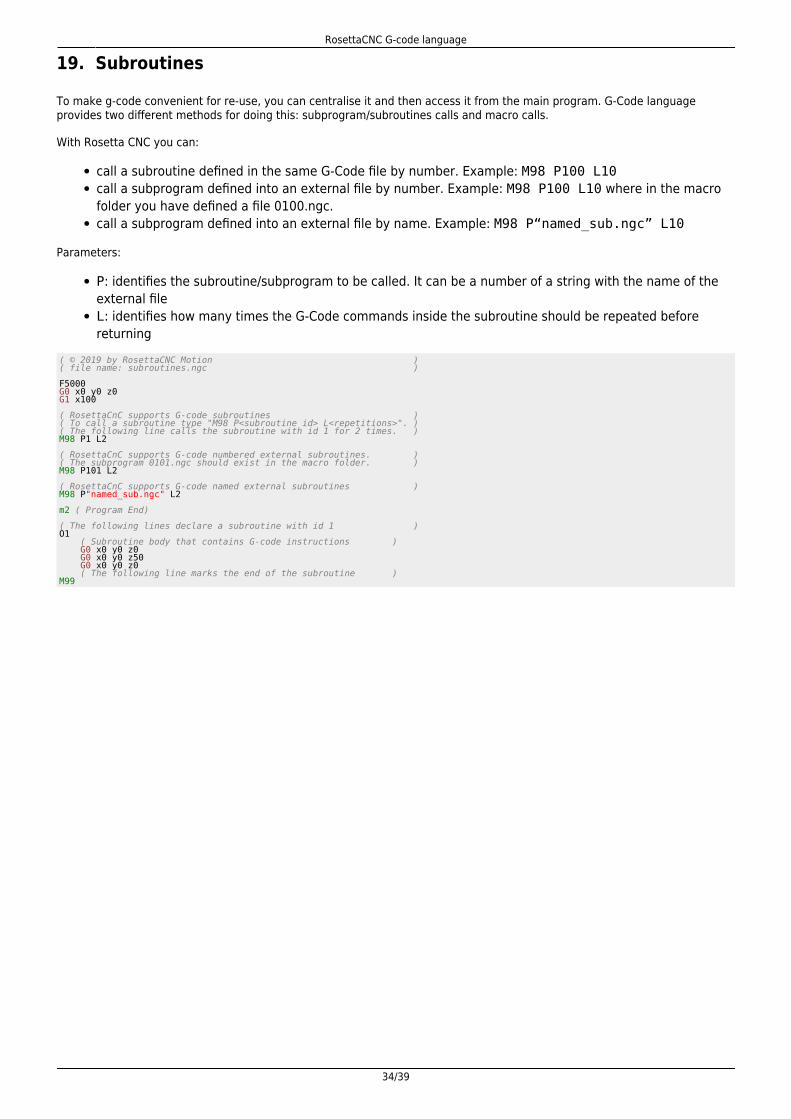
19. Subroutines
To make g-code convenient for re-use, you can centralise it and then access it from the main program. G-Code languageprovides two different methods for doing this: subprogram/subroutines calls and macro calls.
With Rosetta CNC you can:
call a subroutine defined in the same G-Code file by number. Example: M98 P100 L10call a subprogram defined into an external file by number. Example: M98 P100 L10 where in the macrofolder you have defined a file 0100.ngc.call a subprogram defined into an external file by name. Example: M98 P“named_sub.ngc” L10
Parameters:
P: identifies the subroutine/subprogram to be called. It can be a number of a string with the name of theexternal fileL: identifies how many times the G-Code commands inside the subroutine should be repeated beforereturning
( © 2019 by RosettaCNC Motion )( file name: subroutines.ngc ) F5000G0 x0 y0 z0G1 x100 ( RosettaCnC supports G-code subroutines )( To call a subroutine type "M98 P<subroutine id> L<repetitions>". )( The following line calls the subroutine with id 1 for 2 times. )M98 P1 L2 ( RosettaCnC supports G-code numbered external subroutines. )( The subprogram 0101.ngc should exist in the macro folder. )M98 P101 L2 ( RosettaCnC supports G-code named external subroutines )M98 P"named_sub.ngc" L2 m2 ( Program End) ( The following lines declare a subroutine with id 1 )O1 ( Subroutine body that contains G-code instructions ) G0 x0 y0 z0 G0 x0 y0 z50 G0 x0 y0 z0 ( The following line marks the end of the subroutine )M99
RosettaCNC G-code language
35/39
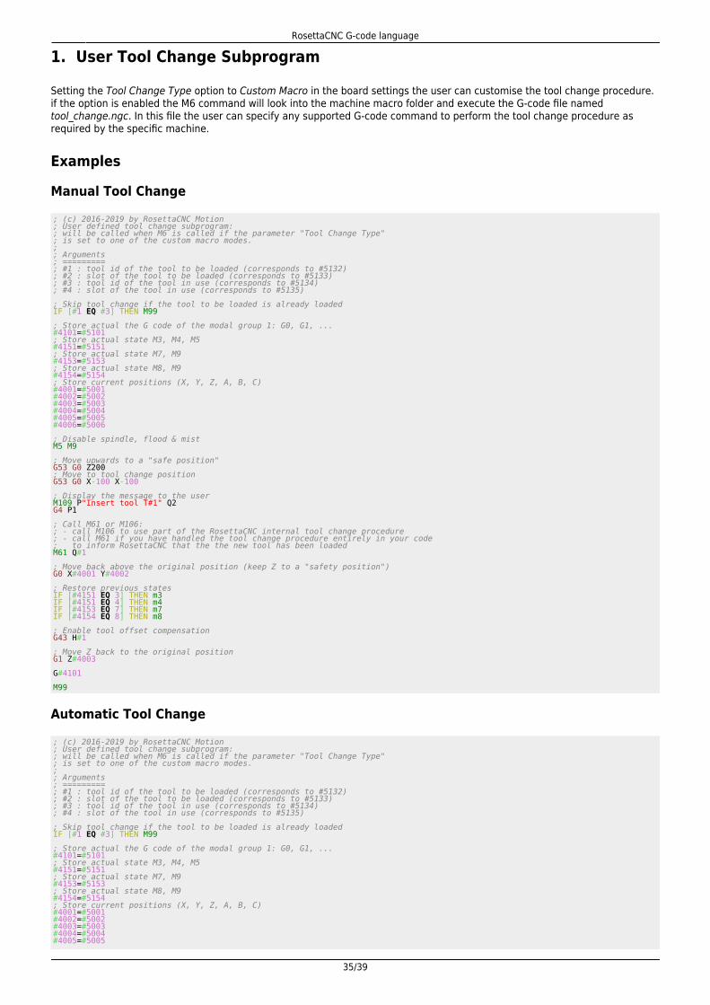
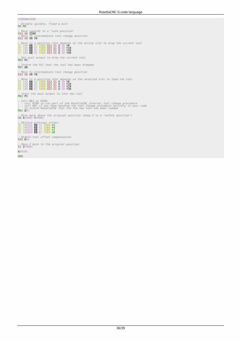
1. User Tool Change Subprogram
Setting the Tool Change Type option to Custom Macro in the board settings the user can customise the tool change procedure.if the option is enabled the M6 command will look into the machine macro folder and execute the G-code file namedtool_change.ngc. In this file the user can specify any supported G-code command to perform the tool change procedure asrequired by the specific machine.
Examples
Manual Tool Change
; (c) 2016-2019 by RosettaCNC Motion; User defined tool change subprogram:; will be called when M6 is called if the parameter "Tool Change Type"; is set to one of the custom macro modes.;; Arguments; =========; #1 : tool id of the tool to be loaded (corresponds to #5132); #2 : slot of the tool to be loaded (corresponds to #5133); #3 : tool id of the tool in use (corresponds to #5134); #4 : slot of the tool in use (corresponds to #5135) ; Skip tool change if the tool to be loaded is already loadedIF [#1 EQ #3] THEN M99 ; Store actual the G code of the modal group 1: G0, G1, ...#4101=#5101; Store actual state M3, M4, M5#4151=#5151; Store actual state M7, M9#4153=#5153; Store actual state M8, M9#4154=#5154; Store current positions (X, Y, Z, A, B, C)#4001=#5001#4002=#5002#4003=#5003#4004=#5004#4005=#5005#4006=#5006 ; Disable spindle, flood & mistM5 M9 ; Move upwards to a "safe position"G53 G0 Z200; Move to tool change positionG53 G0 X-100 X-100 ; Display the message to the userM109 P"Insert tool T#1" Q2G4 P1 ; Call M61 or M106:; - call M106 to use part of the RosettaCNC internal tool change procedure; - call M61 if you have handled the tool change procedure entirely in your code; to inform RosettaCNC that the the new tool has been loadedM61 Q#1 ; Move back above the original position (keep Z to a "safety position")G0 X#4001 Y#4002 ; Restore previous statesIF [#4151 EQ 3] THEN m3IF [#4151 EQ 4] THEN m4IF [#4153 EQ 7] THEN m7IF [#4154 EQ 8] THEN m8 ; Enable tool offset compensationG43 H#1 ; Move Z back to the original positionG1 Z#4003 G#4101 M99
Automatic Tool Change
; (c) 2016-2019 by RosettaCNC Motion; User defined tool change subprogram:; will be called when M6 is called if the parameter "Tool Change Type"; is set to one of the custom macro modes.;; Arguments; =========; #1 : tool id of the tool to be loaded (corresponds to #5132); #2 : slot of the tool to be loaded (corresponds to #5133); #3 : tool id of the tool in use (corresponds to #5134); #4 : slot of the tool in use (corresponds to #5135) ; Skip tool change if the tool to be loaded is already loadedIF [#1 EQ #3] THEN M99 ; Store actual the G code of the modal group 1: G0, G1, ...#4101=#5101; Store actual state M3, M4, M5#4151=#5151; Store actual state M7, M9#4153=#5153; Store actual state M8, M9#4154=#5154; Store current positions (X, Y, Z, A, B, C)#4001=#5001#4002=#5002#4003=#5003#4004=#5004#4005=#5005
RosettaCNC G-code language
36/39
#4006=#5006 ; Disable spindle, flood & mistM5 M9 ; Move upwards to a "safe position"G53 G0 Z200; Move to intermediate tool change positionG53 G0 X0 Y0 ; Move to a position that depends on the active slot to drop the current toolIF [#4 EQ 1] THEN G53 G1 X-10 Y0IF [#4 EQ 2] THEN G53 G1 X-10 Y10IF [#4 EQ 3] THEN G53 G1 X-10 Y20IF [#4 EQ 4] THEN G53 G1 X-10 Y30 ; Set aux1 output to drop the current toolM62 P1 ; Inform the PLC that the tool has been droppedM61 Q0 ; Move to intermediate tool change positionG53 G0 X0 Y0 ; Move to a position that depends on the selected slot to load the toolIF [#2 EQ 1] THEN G53 G1 X-10 Y0IF [#2 EQ 2] THEN G53 G1 X-10 Y10IF [#2 EQ 3] THEN G53 G1 X-10 Y20IF [#2 EQ 4] THEN G53 G1 X-10 Y30 ; reset the aux1 output to lock new toolM63 P1 ; Call M61 or M106:; - call M106 to use part of the RosettaCNC internal tool change procedure; - call M61 if you have handled the tool change procedure entirely in your code; to inform RosettaCNC that the the new tool has been loadedM61 Q#1 ; Move back above the original position (keep Z to a "safety position")G0 X#4001 Y#4002 ; Restore previous statesIF [#4151 EQ 3] THEN m3IF [#4151 EQ 4] THEN m4IF [#4153 EQ 7] THEN m7IF [#4154 EQ 8] THEN m8 ; Enable tool offset compensationG43 H#1 ; Move Z back to the original positionG1 Z#4003 G#4101 M99
RosettaCNC G-code language
37/39
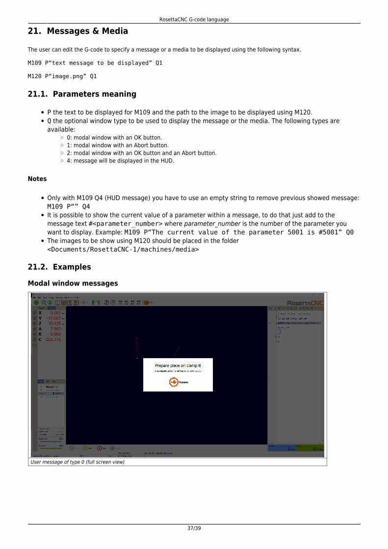
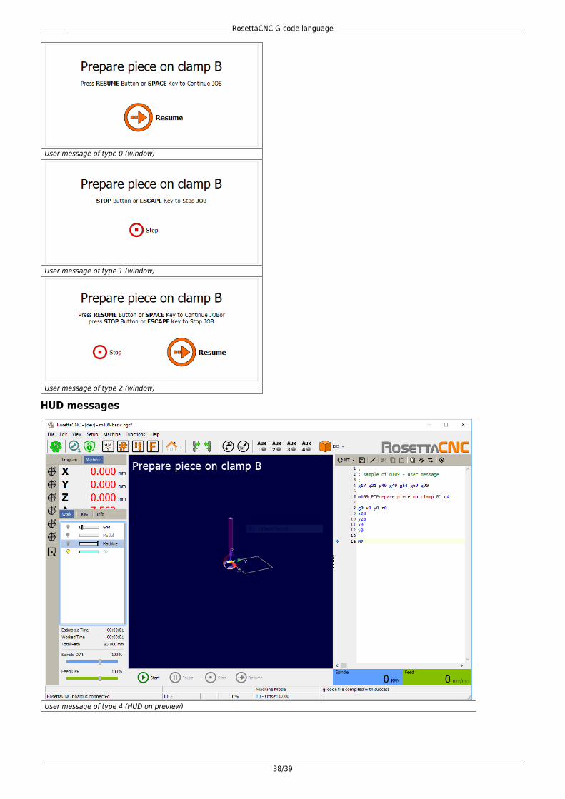
21. Messages & Media
The user can edit the G-code to specify a message or a media to be displayed using the following syntax.
M109 P“text message to be displayed” Q1
M120 P“image.png” Q1
21.1. Parameters meaning
P the text to be displayed for M109 and the path to the image to be displayed using M120.Q the optional window type to be used to display the message or the media. The following types areavailable:
0: modal window with an OK button.1: modal window with an Abort button.2: modal window with an OK button and an Abort button.4: message will be displayed in the HUD.
Notes
Only with M109 Q4 (HUD message) you have to use an empty string to remove previous showed message:M109 P“” Q4It is possible to show the current value of a parameter within a message, to do that just add to themessage text #<parameter_number> where parameter_number is the number of the parameter youwant to display. Example: M109 P“The current value of the parameter 5001 is #5001” Q0The images to be show using M120 should be placed in the folder<Documents/RosettaCNC-1/machines/media>
21.2. Examples
Modal window messages
User message of type 0 (full screen view)
RosettaCNC G-code language
38/39
User message of type 0 (window)
User message of type 1 (window)
User message of type 2 (window)
HUD messages
User message of type 4 (HUD on preview)
RosettaCNC G-code language
39/39
22. Acknowledgement
All those who desire to contribute improving this documentation are encouraged to report inaccuracies or incorrect content.Write to the address: [email protected]
Documento generato automaticamente da RosettaCNC Wiki - https://wiki.rosettacnc.com/Il contenuto wiki è costantemente aggiornato dal team di sviluppo di RosettaCNC, è quindi possibile che la versione onlinecontenga informazioni più recenti di questo documento.