rosemount 370xa natural gas chromatograph€¦ · 1. home screen.route the power supply lines...
TRANSCRIPT

Rosemount™ 370XA Natural Gas ChromatographQuick Start Guide
Quick Start Guide00825-0100-3700, Rev AA
December 2019
1
1
2
3
4
5
6
7
8
9
10
11
12
13
3
2
4
5
6 6
7 7 8
9
10
11
12
13
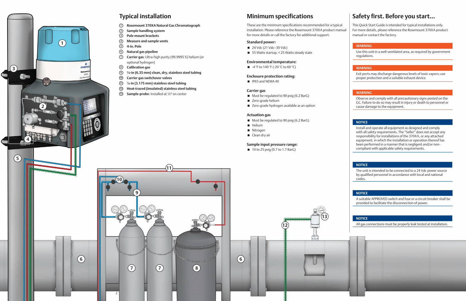
Typical installation Minimum specifications Safety first. Before you start…Rosemount 370XA Natural Gas Chromatograph
Sample handling systemPole mount brackets
Measure and sample vents
4-in. Pole
Natural gas pipeline
Carrier gas: Ultra-high purity (99.9995 %) helium (or
optional hydrogen)Calibration gas
¼-in (6.35 mm) clean, dry, stainless steel tubing
Carrier gas switchover valves
⅛-in (3.175 mm) stainless steel tubing
Heat-traced (insulated) stainless steel tubing
Sample-probe: Installed at ⅓rd on center
These are the minimum specifications recommended for a typical installation. Please reference the Rosemount 370XA product manual for more details or call the factory for additional support.
Standard power: � 24 Vdc (21 Vdc–30 Vdc) � 55 Watts startup, < 25 Watts steady state
Environmental temperature: � -4 °F to 140 °F (-20 °C to 60 °C)
Enclosure protection rating: � IP65 and NEMA 4X
Carrier gas � Must be regulated to 90 psig (6.2 BarG) � Zero-grade helium � Zero-grade hydrogen available as an option
Actuation gas � Must be regulated to 90 psig (6.2 BarG) � Helium � Nitrogen � Clean dry air
Sample input pressure range: � 10 to 25 psig (0.7 to 1.7 BarG)
This Quick Start Guide is intended for typical installations only. For more details, please reference the Rosemount 370XA product manual or contact the factory.
WARNING
Use this unit in a well-ventilated area, as required by government regulations.
WARNING
Exit ports may discharge dangerous levels of toxic vapors; use proper protection and a suitable exhaust device.
WARNING
Observe and comply with all precautionary signs posted on the GC. Failure to do so may result in injury or death to personnel or cause damage to the equipment.
NOTICE
Install and operate all equipment as designed and comply with all safety requirements. The “Seller” does not accept any responsibility for installations of the 370XA, or any attached equipment, in which the installation or operation thereof has been performed in a manner that is negligent and/or non-compliant with applicable safety requirements.
NOTICE
The unit is intended to be connected to a 24 Vdc power source by qualified personnel in accordance with local and national codes.
NOTICE
A suitable APPROVED switch and fuse or a circuit breaker shall be provided to facilitate the disconnection of power.
NOTICE
All gas connections must be properly leak tested at installation.
2 3

Step 1- Mounting the Rosemount 370XARecommended Minimum Installation Clearances
65 in.(1660 mm)
20 in.(50 mm)
25 in.(635 mm)
11 in.(280 mm)
38 in. (665 mm)
8 in.(200 mm)
18 in.(460 mm)
10.849 in.(275.6 mm)
40 in.(1 m)
8 in. (200 mm)
8 in.200 mm
12 in.305 mm
28 in.(705 mm)
40 in.(1000 mm)
1. Attach the bracket to the pole by sliding the plastic inserts onto the pole.
2. Install the two U-bolts through the inserts and the holes in the bracket.
3. The base of the bracket should be 40 in. (1000 mm) from the ground to make the operator interface easy to use.
1. Install ⅜-in. (10 mm) anchors (not supplied) suitable to anchor the weight of the GC, approximately 50 lb. (22 kg) as per the drawing. Use the bracket as a guide to locate the anchors correctly before drilling the holes. The threads of the anchors should protrude from the wall by 1½ in. (40 mm).
2. Mount the bracket to the wall anchors and tighten the nuts. Ensure that the bracket is attached firmly to the wall.
3. Maneuver the GC to insert the two top bolts into the eyelets of the mounting bracket and allow the bolts to drop down and hold the GC loosely on the bracket.
40 in.(1000 mm)
9 in.(230 mm)11 in.
(280 mm)
9 in.
(230 mm)
11 in.
(280 mm)
1. Secure to the floor with four ½-in (12.7 mm) or ⅜-in ( 9.525 mm)cement anchors.
NOTE: The cement foundation should be able to support the weight of the GC, 50 lb. (22 kg), and its accessories, as well as any other utilities that may be installed.
2. Install mounting pole in base; if supplying your own pole, it should be 4 in. (106 mm) in diameter and at least 55 in. (1397 mm) or 4.5 ft (1.39 m) tall.
.5 in.(12 mm)
Mount the bracket.Secure the base.
Mount the bracket on the wall.
Tighten the screws on the bracket.
1. Use a 6 mm hex wrench to screw the top two bolts into the back of the GC without the washers, leaving ½ in (1.27 cm) of thread showing.
4. Screw in the two bottom bolts through the mounting bracket with the washers on. The flat washer should be against the bracket, and the spring washer between the flat washer and the bolt head. Hand tighten these two bolts so that they secure the GC in place.
5. One at a time, remove the top bolts, put on the washers, and screw the bolts into the back of the GC and hand tighten.
40 in.(1000 mm)
1½ in.(40 mm)
4 5
NOTE:Secure base to floor
5½ in.(140 mm)
10⅞ in.(275 mm)
1 2
3
4

2. Connect the atmospheric vents to a vent line of at least ⅜-in (1.905 cm) diameter that is routed to the atmosphere in a safe area to ensure there is no back-pressure created on the vents.
NOTE: The flows out of the vents are: Sample Vent – 10 to 50 cc/min of sample gas for
approximately three and a half minutes of the four-minute cycle.
Measure vent – Continuous flow of less than 1 cc per analysis cycle.
Sample Bypass – Continuous flow of 150 to 200 cc/min of sample gas.
3. Open the carrier gas bottle valves and set the regulator to 80 psig (5.5 BarG) - recommended. 90 psig (6.2 BarG) is the maximum pressure..
4. Open the calibration gas bottle valves and set to 15 psig (1 BarG).
5. Open the sample probe valves and set the sample pressure to 20 psig (1.4 BarG).
6. Leak check all lines with liquid leak-check solution.
7. Open the sample and calibration valves on the sample panel and leak-check up to the fittings on the GC's inlet manifold.
Step 2 – Sample handling system and gas line connections
1
2
Mount the single stream sample plate.Note: This procedure differs when using hydrogen (instead of helium) as a carrier gas.
Connect the gas lines.
1. Using the tubing supplied with the sample system, con-nect the stream, actuation, and calibration gases from the sample plate to the manifold block (also shown on previous page).
1. Use the two 1-in bolts and a 5/32 hex wrench to screw the large mounting bar tightly to the left side of the plate with the angled foot facing the edge of the plate.
Note: To install a multi-stream sample system, please refer to the instructions provided in the sample system installation kit.
2. Use the two 0.5 in bolts and a 5/32 hex wrench to screw the small mounting bar loosely to the right side of the plate with the angled foot facing the edge of the plate.
3. Angle the plate onto the left side of the GC so that the large mounting block fits behind the left edge of the cut-out. Swing the right side of the plate around until it attaches to the right side of the cut-out.
4. Slide the small mounting bar to the right so that it fits behind the right edge of the cut-out. Tighten the small mounting block's screws.
Carrier Gas
BypassVent
Sample Gas
Calibration Gas
Sample VentMeasure VentSample Bypass
Stream 1Calibration
Carrier/actuation
NOTE:Be careful not to crimp the sample system's tubing when bendingthem to connect to the GC's manifold block. Doing so will inhibitgas flow. Ensure all caps on tubing connections have been removed.
6 7
CalibrationActuation
Manifold block
Stream 1Carrier
Manifold block
Helium carrier gas
Hydrogen carrier gas
Stream 1Calibration
CarrierActuation
Atmospheric reference vent (no connection)

Step 3 – Wiring Step 4 – Startup
1. Route the power supply lines through the lower left or right cable entry – whichever is the most convenient.2. Connect power wires to TB8. DO NOT APPLY POWER YET.3. Route the communication wiring through the lower right cable entry. If additional separation of wiring is required, use the upper right
cable entry for the additional signal wiring. Refer to the Terminal Board Key Map for communications wiring.4. Connect the signal wiring as shown in the diagrams below.
Local Operator Interface
Display icons Main Menu Display Options
To display a desired letter, repeatedly press the appropriate key until the letter displays. For example, to display the letter “H”, press the 4 key three times.
1. Turn on the power. The local operator interface (LOI) will show the Emerson logo while the software starts up, and then it will show the home screen.
Full color screen480 x 272 pixels
UpExit/Cancel
AlphanumericalKeypad
Enter Down
Right
Left
Select/Edit
No alarms
Unacknowledged alarm(s)
Active alarm(s)
Security switch unlocked
Security switch locked
� View � Hardware � Application � Logs � GC Controls � Tools
8 9
1 Connect power and communications wiring. 1 Power the GC.
2 How to enter letters from the keypad.

3. Press the key to continue, and enter in the uncertainty values from the certificate.
NOTE: If the calibration certificate does not include uncertainty values, use the default 2 % setting.
4. Press the key to continue, and enter the energy value for the calibration blend.
NOTE: The calculated value shown on the display is calculated using the same C6+ Ratio of C6/C7/C8 as is used in the stream calculations. This value may differ to the value on the certificate which may use a hexane only energy content. Use the calculated value from the screen to avoid nuisance alarms during calibrations.
5. Press to save and close the screen.
Wait for the oven to reach the operating temperature.1. From the Main Menu, navigate to the Hardware menu and select Heaters.2. Wait for the Heater Out of Range alarm to clear. This should take approximately two
hours from when power is applied.
Clear alarms.1. From the Main Menu, navigate to the View menu and select Current Alarms.2. Press [2] to acknowledge and clear all alarms.3. Press to return to the Main Menu.
Purge calibration gas.1. From the Main Menu, navigate to the GC Control menu and select Single Stream.2. Select the 4-Cal stream and check the Purge Stream for 60 seconds option.3. Let the GC run for at least 30 minutes.
Calibrate the GC.1. From the Main Menu, navigate to the GC Control menu and select Halt to stop the
current analysis.2. When the analysis cycle finishes, select Calibration from the control menu.3. Select Purge Stream for 60 seconds and a Normal calibration type and press to
start the calibration cycle.4. Confirm at the end of the calibration cycle no alarms where generated. If alarms
were activated, refer to the manual that is included on the MON2020 CD-ROM that is shipped with the GC.
Put the GC into service.1. From the Main Menu, navigate to the GC Control menu and select Auto Sequence.2. Select Purge stream for 60 seconds and press to start the analysis cycle.
For more configuration and operating instructions, refer to the manual that is included on the MON2020 CD or USB that is shipped with the GC, and is available online at www.Emerson.com/RosemountGasAnalysis
As the GC warms up to operating temperature and purges the carrier gas through the system, configure the GC’s site-specific settings, such as the calibration gas values and communication settings.
Note: The Login screen will appear if you are not logged in.Enter your user name and password. The default values for Rosemount 370XA GCs is:User: EMERSONPassword: (blank)
Configure the time and date.1. From the Main Menu, select Set GC Time from the Tools menu.2. Confirm the time and date is correct. To change the time or date, use the arrow keys
to navigate to the field to change and press the Select/Edit key to edit.3. Press the key to save the changes, or the key to discard changes and exit to the
main menu.
Configure the serial port settings.4. From the Main Menu, use the arrow keys to navigate to the Application menu and
select the Communications option.5. Use the arrow keys to navigate through the various settings and press the Select/Edit
key to edit the appropriate values. The settings must match the settings of the host device communicating to the GC on that port.
6. When you have finished making changes, press the key to save changes and close the screen.
Configure the Ethernet port.1. From the Main Menu, use the arrow keys to navigate to the Application menu and
select the TCP/IP Settings option.2. Use the arrow keys to navigate through the various settings and press the Select/Edit
key to edit the appropriate values. The settings must match the settings of the host device communicating to the GC on that port.
3. When you have finished making changes, press the key to save changes and close the screen.
If required, you can access the Analog Input, Analog Output, Digital Input, and Digital Outputs settings from the Hardware menu. Refer to the manual for further information
Enter the calibration gas values.1. From the main menu, navigate to the Application menu and select Calibration Gas
Info.2. Press the Select/Edit edit key and enter the calibration gas concentration values for
each component. Note that the methane value will be calculated automatically. You can use this as a check against the value on the certificate to ensure all the values have been entered correctly.
Step 5 – Configure and calibrate the GC.
Note: If the unit is not in Idle mode, then do the following: 1. Press 3 on the keypad to go to the GC Control menu.2. Press the down arrow to highlight the Halt command.3. Press on the keypad and then follow the prompts.
Home Screen Calibration Gas Uncertainty Screen
Main Menu, Showing the Set GC Time Calibration Gas Energy Content Screen
Set GC Time Screen Heater Screen Showing Current PWM
Communication Screen for the Serial Ports Selecting the Cal. Gas for a Single Stream Analysis
TCP/IP Settings Screen Starting the First Communication Cycle
Calibration Concentration Screen Starting the 370XA Analyzing Stream Gas
10 11
©2019 Emerson. All rights reserved.
The Emerson logo is a trademark and service mark of Emerson Electric Co. Rosemount is mark of one of the Emerson family of companies. All other marks are the property of their respective owners.
00825-0100-3700Rev AA
2019
ASIA-PACIFICEmerson Automation Solutions1 Pandan CrescentSingapore 128461Republic of Singapore +65 6 777 8211 +65 6 777 0947 [email protected]
MIDDLE EAST AND AFRICAEmerson Automation SolutionsEmerson FZE Jebel Ali Free ZoneDubai, United Arab Emirates,P.O. Box 17033 +971 4 811 8100 +971 4 886 5465 [email protected]
AMERICASEmerson Automation Solutions 10241 West Little York, Suite 200Houston, TX 77040 USA Toll Free + 866 422 3683 +1 713 396 8880 (North America) +1 713 396 8759 (Latin America) +1 713 466 8175 [email protected]
YouTube.com/user/RosemountMeasurement
Facebook.com/Rosemount
Twitter.com/Rosemount_News
Linkedin.com/company/Emerson-Automation-Solutions
EUROPEEmerson Automation SolutionsNeuhofstrasse 19a PO Box 1046CH-6340 BaarSwitzerland + 41 (0) 41 768 6111 + 41 (0) 41 768 6300 [email protected]