room controllers se7600e series - schneider electric
TRANSCRIPT

SE7600E SeriesRTU Terminal Equipment Controller with IAQ Control
Room Controllers 01
Installation GuideFor Commercial HVAC Applications
CONTENTSInstallation 2 Location 2 Installation 2Operation Overview 3 Features overview 3Model Chart 3 Network ready 4Terminal, Identification and Function 4 Screw terminal arrangement and wiring 4 Main outputs wiring 4Typical Applications 5 Remote sensor accessories 5Configuring and Status Display Instructions 7 Status display 7User interface 8 User configuring instructions menu 8 Local keypad interface 8Installer Configuration Parameter Menu 13 Fresh AIr Damper Control Sequences 21Economizer Control Mode Only 21Economizer Mode & Fresh-Air Measurement Station 21Economizer Mode & CO2 Level Control 22Economizer Mode & CO2 Level Control & Fresh-Air Measurement Station 22Specifications 23Drawing & Dimensions 24

All brand names, trademarks and registered trademarks are the property of their respective owners. Information contained within this document is subject to change without notice.Schneider Electric One High Street, North Andover, MA 01845 USA Telephone: +1 978 975 9600 Fax: +1 978 975 9674 http://www.schneider-electric.com/buildings
II-SE7000-SE7600E-A4.EN.4.2013.v1 April 2013
© 2
013
Sch
neid
er E
lect
ric. A
ll rig
hts
rese
rved
.
SE7600E SeriesInstallation Guide 2
Figure-1 Opening the Cover
Figure-2 Opening the PCB
Figure-3 Terminal Block Reinstall
INSTALLATIONInspection• RemovethesecurityscrewonthebottomoftheTerminalEquipmentControl-lercover.
• OpentheunitbypullingonthebottomsideofFanCoilTerminalEquipmentController(Figure-1).
• Removethewiringterminalsfromthesticker.• PleasereadtheFCCIDandIClabelinstalledinthecoveruponremovalofthecoverforthewirelessproducts.
Location• Donotinstallonanoutsidewall.• Installawayfromanydirectheatsource.• Donotinstallnearanairdischargegrill.• Donotlocateindirectsunradiation.• NothingshouldrestrictverticalaircirculationtotheTerminalEquipmentCon-troller.
Installation1. SwingopentheFanCoilTerminalEquipmentControllerPCBtotheleftbypressingthetwoPCBretainingtabs(Figure-2).
2. Pullthecables6"outfromthewall.3. Thewallsurfacemustbeflatandclean.4. Insertthecableintothecentralholeofthebase.5. Alignthebaseandmarkthelocationofthetwomountingholesonthewall.Installthepropersideofthebaseupward.
6. Installthescrewanchorsinthewall.7. Insertscrewsinthemountingholesoneachsideofthebase(Figure-2).8. Gentlyswingbackthecircuitboardonthebaseandpushonituntilthetabslockit.
9. Stripeachwire1/4inchfromtheend.10.Inserteachwireaccordingtothewiringdiagram.11.Gentlypushexcesswiringbackintotheholeinthebase.12.Reinstallthewiringterminalsintheircorrectlocations(Figure-3).13.Reinstallthecover(topsidefirst)andgentlypushanyextrawirelengthbackintotheholeinthewall.
14.Installthesecurityscrew.
InstallationIf replacing an existing Terminal Equipment Controller, label the wires before removal of the Terminal Equipment Controller.
Electronic controls are static sensitive devices. Discharge yourself properly before manipulating and installing the Terminal Equipment Controller.
A short circuit or wrong wiring may permanently damage the Terminal Equipment Controller or the equipment.
All SE7000 series Terminal Equipment Controllers are designed for use as operating controls only and are not safety devices. These instruments have undergone rigorous tests and verification prior to shipping to ensure proper and reliable operation in the field. Whenever a control failure could lead to personal injury and/or loss of property, it becomes the responsibility of the user / installer / electrical system designer to incorporate safety devices (such as relays, flow switch, thermal protections, etc…) and/or an alarm system to protect the entire system against such catastrophic failures. Tampering with the devices or unintended application of the devices will result in a void of warranty.

© 2
013
Sch
neid
er E
lect
ric. A
ll rig
hts
rese
rved
.
3SE7600E SeriesInstallation Guide
All brand names, trademarks and registered trademarks are the property of their respective owners. Information contained within this document is subject to change without notice.Schneider Electric One High Street, North Andover, MA 01845 USA Telephone: +1 978 975 9600 Fax: +1 978 975 9674 http://www.schneider-electric.com/buildings
II-SE7000-SE7600E-A4.EN.4.2013.v1 April 2013
THEORY OF OPERATIONTheSE76X6EusesaSchneiderElectricproprietaryadaptivelogicalgorithmtocontrolthespacetem-perature.Thisalgorithmcontrolstheheatingandairconditioningsystemtominimizeovershootwhilestillprovidingcomfort.ItprovidesexceptionalaccuracyduetoitsuniquePItimeproportioningcontrolalgo-rithm,whichvirtuallyeliminatesthetemperatureoffsetassociatedwithtraditional,differential-based,on-offTerminalEquipmentControllers.NotethecomparisoninFigure-4.
Figure-4 On-Off Mechanical vs PI Electronic Control
FEATURES OVERVIEW•7dayschedulemodels,2or4events.
•C02controllogicbasedonfreshairvolumeorfreshairdamperposition.
•FreshairdamperoutputforbuildingCO2levelcontrol.
•Gas,oilorelectricsystemcompatibility.
•Remoteoutdoorsensingcapabilityforaddedflex-ibility. Systemmodeheatingandcoolinglockout.
•Remotedischargeairsensorinputformonitoringandcontrolpurpose. Systemefficiencyfeedback. Dischargehighlimitheatinglockout. Dischargelowlimitcoolinglockout. Remotereturnairsensorinputthatreplaces internalonboardsensor. Systemefficiencyfeedback.
•Passwordprotectedconfigurationmenuandlock-ablekeypadsforsecurity.
•Automaticsmartfanoperationsavesenergyduringunoccupiedperiods.
•NonvolatileEEPROMmemorypreventslossofparametersduringpowershortage.
•ConfigurableSPSToutputrelayonschedulingmodelsforlighting,exhaustfanorfreshaircontrol.
•6hourtypicalreservetimeforclockincaseofpowerloss.
Easy configuration and self-binding operation
•Easyconfigurationwithoutusinganyspecialsoftwareoradditionaltools.•Canbeusedasstand-aloneorwithBACnet™MS-TPsupervisioncontrollerformonitoringpurposed.•TrulyscalableintermsofsupportednumberofzonesandRTUunits.
SE7300 Series Ordering
SE76 5 E 5 0 W45
Example: SE7656E5045W
Economizer / RH Sensor:
-6 = For Scheduling (Programmable models)
Programmability:-0 = No local scheduling/ Non-programmable
-5 = Local scheduling/ Programmable
PIR Options:-50 = PIR ready/cover not included-55 = Factory assembled with PIR cover
Application:-E = With Indoor Air Quality (IAQ) Control
Communication Options:-B = BACnet MS/TP
-W = Zigbee wireless
- = Network Ready
®
®
Wireless communicationPIR ready/cover not includedIAQ ControlLocal schedulingLocal scheduling
-0 = No local scheduling/ Non-programmable
6
MODEL CHART
All brand names, trademarks and registered trademarks are the property of their respective owners. Information contained within this document is subject to change without notice.Schneider Electric One High Street, North Andover, MA 01845 USA Telephone: +1 978 975 9600 Fax: +1 978 975 9674 http://www.schneider-electric.com/buildings
II-SE7000-SE7600E-A4.EN.4.2013.v1 April 2013
© 2
013
Sch
neid
er E
lect
ric. A
ll rig
hts
rese
rved
.
SE7600E SeriesInstallation Guide 4
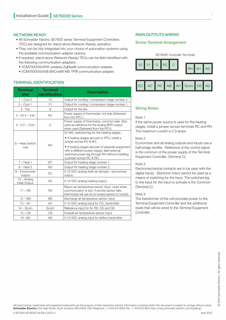
NETWORK READY•AllSchneiderElectricSE7600seriesTerminalEquipmentControllers(TEC)aredesignedforstand-alone(NetworkReady)operation.•Theycanbefullyintegratedintoyourchoiceofautomationsystemsusingtheavailablecommunicationadapteroptions.•Ifrequired,stand-alone(NetworkReady)TECscanbefieldretrofittedwiththefollowingcommunicationadapters:•VCM7000V5045WwirelessZigBee®communicationadapter.•VCM7600V5045BBACnet®MS-TP®communicationadapter.
TERMINAL IDENTIFICATION
Terminal Use
Terminal Identification
Description
1–Cool2 Y2 Outputforcooling/compressorstagenumber2.
2–Cool1 Y1 Outputforcooling/compressorstagenumber1.
3-Fan G Outputforthefan.
4-24V~Hot RCPowersupplyofthermostat,hotside(DeliveredfromtheRTU).
5-0V~Com CPowersupplyofthermostat,commonside.AlsousedasreferencefortheanalogBPDoutputwhenused(DeliveredfromtheRTU).
6–HeatSwitchLeg
RH
24VACswitchedlegfortheheatingstages.
•IfheatingstagesarepartorRTU,installajumperacrossRC&RH.
•Ifheatingstagesarepartofseparateequipmentwithadifferentpowersupply,feedexternalswitchedpowerlegthroughRHwithoutinstallingajumperacrossRC&RH.
7–Heat1 W1 Outputforheatingstagenumber1.
8–Heat2 W2 Outputforheatingstagenumber2.9–Economizer
OutputEC
0-10VDCanalogfreshairdamper/economizeroutput.
10–AnalogHeatOutput
AO 0-10VDCanalogheatingoutput.
11–RS RSReturnairtemperaturesensorinput.Usedwhencommunicationislost.Ifremotesensorfails,thermostatwilluseitson-boardsensortocontrol.
12–MS MS Dischargeairtemperaturesensorinput
13–AI1 AI1 0-10VDCanaloginputforCO2transmitter
14–Scom Scom ReferenceinputforAI,RS,OSandDS
15–OS OS Outsideairtemperaturesensorinput
16–AI2 AI2 0-10VDCanaloginputforairflowtransmitter
Screw Terminal Arrangement
RH W1 W2Y2 Y1 G RC C
EC AO RS MS AI1 Scom OS AI2
SE76XXEControllerTerminals
Wiring Notes
Note1Ifthesamepowersourceisusedfortheheatingstages,installajumperacrossterminalsRCandRH.Themaximumcurrentis2.0amps.
Note2Economizerandallanalogoutputsandinputsuseahalfbridgerectifier.ReferenceofthecontrolsignalisthecommonofthepowersupplyoftheTerminalEquipmentController.(TerminalC).
Note3 Electromechanicalcontactsaretobeusedwiththedigitalinputs.Electronictriacscannotbeusedasameansofswitchingfortheinput.TheswitchedlegtotheinputfortheinputtoactivateistheCommon(TerminalC).
Note4ThetransformeroftheunitprovidespowertotheTerminalEquipmentControllerandtheadditionalloadsthatwillbewiredtotheTerminalEquipmentController.
MAIN OUTPUTS WIRING

© 2
013
Sch
neid
er E
lect
ric. A
ll rig
hts
rese
rved
.
5SE7600E SeriesInstallation Guide
All brand names, trademarks and registered trademarks are the property of their respective owners. Information contained within this document is subject to change without notice.Schneider Electric One High Street, North Andover, MA 01845 USA Telephone: +1 978 975 9600 Fax: +1 978 975 9674 http://www.schneider-electric.com/buildings
II-SE7000-SE7600E-A4.EN.4.2013.v1 April 2013
TYPICAL APPLICATIONS
Main Outputs Wiring
REMOTE SENSOR ACCESSORIES Applicable Models
Model Description Application Picture
SE3010W1045 Roomsensor
•Remoteroomsensing•3thermistorswith2dipswitchesareprovidedwitheachsensorforvariousaveragingcombinations
SE3020W1045
RoomsensorwithtemporaryoverridekeyandoccupancyLED
•RemoteroomsensingwithoverridekeyandoccupancyLED•3thermistorswith2dipswitchesareprovidedwitheachsensorforvariousaveragingcombinations
Y2 Y1 G RH EC AO AI1 OS AI2Scom
Cool Stage
2
T1
0-10 VDC
24V Com
0-10 VDC
24V Com
Fan
Cool Stage
1 0-10 VDCInput
0-10 VDCInput
24V AC
Jumper J1
RS
ReturnAir
Sensor
MS
MixedAir
Sensor
Heat Stage
2
Heat Stage
1
Controller Internal Wiring
System Wiring
RC C W1 W2
OutdoorSensor
All brand names, trademarks and registered trademarks are the property of their respective owners. Information contained within this document is subject to change without notice.Schneider Electric One High Street, North Andover, MA 01845 USA Telephone: +1 978 975 9600 Fax: +1 978 975 9674 http://www.schneider-electric.com/buildings
II-SE7000-SE7600E-A4.EN.4.2013.v1 April 2013
© 2
013
Sch
neid
er E
lect
ric. A
ll rig
hts
rese
rved
.
SE7600E SeriesInstallation Guide 6
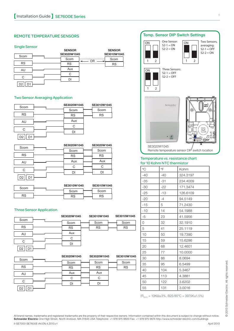
Single Sensor
Two Sensor Averaging Application
Three Sensor Application
Temp. Sensor DIP Switch Settings
Temperature vs. resistance chart for 10 Kohm NTC thermistorºC ºF Kohm
-40 -40 324.3197
-35 -31 234.4009
-30 -22 171.3474
-25 -13 126.6109
-20 -4 94.5149
-15 5 71.2430
-10 14 54.1988
-5 23 41.5956
0 32 32.1910
5 41 25.1119
10 50 19.7390
15 59 15.6286
20 68 12.4601
25 77 10.0000
30 86 8.0694
35 95 6.5499
40 104 5.3467
45 113 4.3881
50 122 3.6202
55 131 3.0016
(R25°C=10KΩ±3%,B25/85°C=3975K±1.5%)
SENSORSE3020W1045
SENSORSE3010W1045
SE3020W1045 SE3010W1045
SE3020W1045
SE3010W1045
SE3020W1045
SE3010W1045
SE3020W1045 SE3010W1045 SE3010W1045
SE3020W1045 SE3020W1045 SE3010W1045
ScomScom Scom
RS
AU
C
D2 D1
RS RSAux
C
DI
OR
ScomRSAux
C
DI
ScomRSAux
C
DI
Scom
RS
AU
C
D2 D1
ScomRSAux
C
DI
ScomRS
Scom
RS
AU
C
D2 D1
ScomRS
ScomRS
Scom
RS
ScomRSAux
C
DI
ScomRS
ScomRS
Scom
RS
AU
C
D2 D1
ScomRSAux
C
DI
ScomRSAux
C
DI
ScomRS
Scom
RS
AU
C
D2 D1
SE3010W1045
ON
1 2
ON
1 2
One Sensor: S2-1 = ONS2-2 = ON
Two Sensors, averaging:S2-1 = OFFS2-2 = ON
ON
1 2
Three Sensors:S2-1 = OFFS2-2 = OFF
SE3020W1045RemotetemperaturesensorDIPswitchlocation
REMOTE TEMPERATURE SENSORS
© 2
013
Sch
neid
er E
lect
ric. A
ll rig
hts
rese
rved
.
7SE7600E SeriesInstallation Guide
All brand names, trademarks and registered trademarks are the property of their respective owners. Information contained within this document is subject to change without notice.Schneider Electric One High Street, North Andover, MA 01845 USA Telephone: +1 978 975 9600 Fax: +1 978 975 9674 http://www.schneider-electric.com/buildings
II-SE7000-SE7600E-A4.EN.4.2013.v1 April 2013
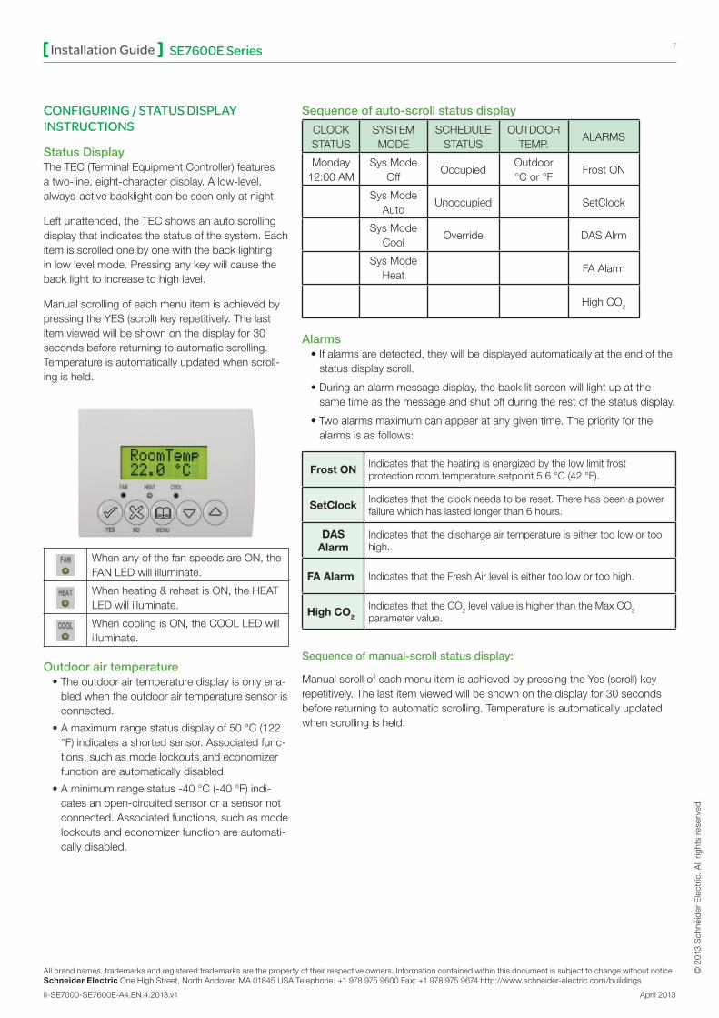
CONFIGURING / STATUS DISPLAY INSTRUCTIONS
Status DisplayTheTEC(TerminalEquipmentController)featuresatwo-line,eight-characterdisplay.Alow-level,always-activebacklightcanbeseenonlyatnight.
Leftunattended,theTECshowsanautoscrollingdisplaythatindicatesthestatusofthesystem.Eachitemisscrolledonebyonewiththebacklightinginlowlevelmode.Pressinganykeywillcausethebacklighttoincreasetohighlevel.
ManualscrollingofeachmenuitemisachievedbypressingtheYES(scroll)keyrepetitively.Thelastitemviewedwillbeshownonthedisplayfor30secondsbeforereturningtoautomaticscrolling.Temperatureisautomaticallyupdatedwhenscroll-ingisheld.
WhenanyofthefanspeedsareON,theFANLEDwillilluminate.
Whenheating&reheatisON,theHEATLEDwillilluminate.
WhencoolingisON,theCOOLLEDwillilluminate.
Outdoor air temperature •Theoutdoorairtemperaturedisplayisonlyena-bledwhentheoutdoorairtemperaturesensorisconnected.
•Amaximumrangestatusdisplayof50°C(122°F)indicatesashortedsensor.Associatedfunc-tions,suchasmodelockoutsandeconomizerfunctionareautomaticallydisabled.
•Aminimumrangestatus-40°C(-40°F)indi-catesanopen-circuitedsensororasensornotconnected.Associatedfunctions,suchasmodelockoutsandeconomizerfunctionareautomati-callydisabled.
Sequence of auto-scroll status display
CLOCKSTATUS
SYSTEMMODE
SCHEDULESTATUS
OUTDOORTEMP.
ALARMS
Monday12:00AM
SysModeOff
OccupiedOutdoor°Cor°F
FrostON
SysModeAuto
Unoccupied SetClock
SysModeCool
Override DASAlrm
SysModeHeat
FAAlarm
HighCO2
Alarms•Ifalarmsaredetected,theywillbedisplayedautomaticallyattheendofthestatusdisplayscroll.
•Duringanalarmmessagedisplay,thebacklitscreenwilllightupatthesametimeasthemessageandshutoffduringtherestofthestatusdisplay.
•Twoalarmsmaximumcanappearatanygiventime.Thepriorityforthealarmsisasfollows:
Frost ON Indicatesthattheheatingisenergizedbythelowlimitfrostprotectionroomtemperaturesetpoint5.6°C(42°F).
SetClock Indicatesthattheclockneedstobereset.Therehasbeenapowerfailurewhichhaslastedlongerthan6hours.
DAS Alarm
Indicatesthatthedischargeairtemperatureiseithertoolowortoohigh.
FA Alarm IndicatesthattheFreshAirleveliseithertoolowortoohigh.
High CO2
IndicatesthattheCO2levelvalueishigherthantheMaxCO2parametervalue.
Sequence of manual-scroll status display:
ManualscrollofeachmenuitemisachievedbypressingtheYes(scroll)keyrepetitively.Thelastitemviewedwillbeshownonthedisplayfor30secondsbeforereturningtoautomaticscrolling.Temperatureisautomaticallyupdatedwhenscrollingisheld.
All brand names, trademarks and registered trademarks are the property of their respective owners. Information contained within this document is subject to change without notice.Schneider Electric One High Street, North Andover, MA 01845 USA Telephone: +1 978 975 9600 Fax: +1 978 975 9674 http://www.schneider-electric.com/buildings
II-SE7000-SE7600E-A4.EN.4.2013.v1 April 2013
© 2
013
Sch
neid
er E
lect
ric. A
ll rig
hts
rese
rved
.
SE7600E SeriesInstallation Guide 8
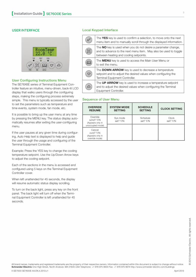
USER INTERFACE
User Configuring Instructions MenuTheSE76X6EseriesofTerminalEquipmentCon-trollerfeatureanintuitive,menu-driven,back-litLCDdisplaythatwalksusersthroughtheconfiguringsteps,makingtheconfiguringprocessextremelysimple.Thismenuistypicallyaccessedbytheusertosettheparameterssuchastemperatureandtimeevents,systemmode,fanmode,etc.
ItispossibletobringuptheusermenuatanytimebypressingtheMENUkey.Thestatusdisplayauto-maticallyresumesafterexitingtheuser-configuringmenu.
Iftheuserpausesatanygiventimeduringconfigur-ing,AutoHelptextisdisplayedtohelpandguidetheuserthroughtheusageandconfiguringoftheTerminalEquipmentController.
Example:PresstheYESkeytochangethecoolingtemperaturesetpoint.UsetheUp/DownArrowkeystoadjustthecoolingsetpoint.
Eachofthesectionsinthemenuisaccessedandconfiguredusing5keysontheTerminalEquipmentControllercover.
Whenleftunattendedfor45seconds,thedisplaywillresumeautomaticstatusdisplayscrolling.
Toturnonthebacklight,pressanykeyonthefrontpanel.ThebacklightwillturnoffwhentheTermi-nalEquipmentControllerisleftunattendedfor45seconds.
Local Keypad Interface
TheYESkeyisusedtoconfirmaselection,tomoveontothenextmenuitemandtomanuallyscrollthroughthedisplayedinformation.
TheNOkeyisusedwhenyoudonotdesireaparameterchange,andtoadvancetothenextmenuitem.Mayalsobeusedtotogglebetweenheatingandcoolingsetpoints.
TheMENUkeyisusedtoaccesstheMainUserMenuortoexitthemenu.
TheDOWN ARROWkeyisusedtodecreaseatemperaturesetpointandtoadjustthedesiredvalueswhenconfiguringtheTerminalEquipmentController.
TheUP ARROWkeyisusedtoincreaseatemperaturesetpointandtoadjustthedesiredvalueswhenconfiguringtheTerminalEquipmentController.
Sequence of User Menu
OVERRIDERESUME
SYSTEM MODE SETTING
SCHEDULE SETTING
CLOCK SETTING
Overrideschd?Y/N
(Appearsonlyinunoccupiedmode)
Sysmodeset?Y/N
Scheduleset?Y/N
Clockset?Y/N
Cancelovrd?Y/N
(Appearsonlyinoverridemode)

© 2
013
Sch
neid
er E
lect
ric. A
ll rig
hts
rese
rved
.
9SE7600E SeriesInstallation Guide
All brand names, trademarks and registered trademarks are the property of their respective owners. Information contained within this document is subject to change without notice.Schneider Electric One High Street, North Andover, MA 01845 USA Telephone: +1 978 975 9600 Fax: +1 978 975 9674 http://www.schneider-electric.com/buildings
II-SE7000-SE7600E-A4.EN.4.2013.v1 April 2013
A) Override an unoccupied period
Overrideschd? Y/N
ThismenuwillappearonlywhentheTerminalEquipmentControllerisinunoccupiedmode.
AnsweringyestothispromptwillcausetheTerminalEquipmentControllertogointooccupiedmodeforanamountoftimeequaltotheparameter“TOccTime”(1to12hours).
B) Resume regular scheduling
Cancelovrd? Y/N
Thismenudoesnotappearinregularoperation.ItwillappearonlywhentheTerminalEquipmentControllerisinUnoccupiedoverridemode.
Answering“Yes”tothisquestionwillcausetheTerminalEquipmentControllertoresumetheregularsetpointsandscheduling.
C) Temperature setpoints
Permanent setpoint changes
Temperatset? Y/N
Thismenupermitstheadjustmentofallpermanenttemperaturesetpoints(occupiedandunoccupied)aswellasthedesiredtemperatureunits(°For°C).PermanentsetpointsarewrittentoRAMandEEPROM.
COOLING SETPOINTOCCUPIED MODE
HEATING SETPOINTOCCUPIED MODE
COOLING SETPOINTUNOCCUPIED MODE
Cooling
set?Y/NNonext→Yesdown↓
Heating
set?Y/NNonext→Yesdown↓
UnoccCL
set?Y/NNonext→Yesdown↓
Use▲▼keystosetvalue,pressYeskeytoconfirm
Cooling
70.0°F(21°C)Use▲▼Tosetvalue
Heating
68.00°F(20°C)Use▲▼Tosetvalue
UnoccCL
80.0°F(26.6°C)Use▲▼Tosetvalue
HEATING SETPOINTUNOCCUPIED MODE
°F OR °CDISPLAY SETTING
UnoccHT
set?Y/NNonext→Yesdown↓
°For°C
set?Y/NNonext→Yesdown↓
Use▲▼keystosetvalue,pressYeskeytoconfirm
UnoccHT
60.0°F(15.5°C)Use▲▼Tosetvalue
Units
°F(°C)Use▲▼Tosetvalue
Temporary setpoint changes
TemporarysetpointscanbemodifiedthroughtheUpArrowkey(▲)andtheDownArrowkey(▼).Theuserwillbepromptedwiththepresentmode(HeatingorCooling)oftheTerminalEquipmentControlleranditssetpoint.TheUp(▲)arrowkeywillincrementthesetpointby0.5degree(ForC).TheDown(▼)arrowkeywilldecrementthesetpointby0.5degree(ForC).PresstheYESkeytoacceptthenewsetpoint.
Localchangestotheheatingorcoolingsetpointsmadebytheuserdirectlywiththeup/downarrowkeysaretemporary.TheywillremaineffectiveforthedurationspecifiedbyToccTime.SetpointswillrevertbacktotheirdefaultvalueafterinternaltimerToccTimeexpires.Ifapermanentchangetothesetpointsisrequired,usetheTemperat set? Y/Nmenu.
D) System mode setting
Sys modeset ? Y/N
Thismenuisaccessedtosetsystemmodeoperation.Usethearrow▲▼keystosetthevalue,theYESkeytoconfirmthechange.
Sys modeauto
Automatic modeAutomaticchangeovermodebetweenheatingandcoolingoperation
Sys modecooling
Cooling modeCoolingoperationmodeonly.
Sys modeheating
Heating modeHeatingoperationmodeonly.
Sys modeemergency
Emergency heat mode (Heatpumpmodelsonly.)Forcedauxiliaryheatoperationmodeonly.
Sys modeoff
Off mode Normalcoolingorheatingoperationdisabled.Ifenabledininstallerpara-meters,onlytheautomaticheatingfrostprotectionat50°F(10°C)isenabled.
All brand names, trademarks and registered trademarks are the property of their respective owners. Information contained within this document is subject to change without notice.Schneider Electric One High Street, North Andover, MA 01845 USA Telephone: +1 978 975 9600 Fax: +1 978 975 9674 http://www.schneider-electric.com/buildings
II-SE7000-SE7600E-A4.EN.4.2013.v1 April 2013
© 2
013
Sch
neid
er E
lect
ric. A
ll rig
hts
rese
rved
.
SE7600E SeriesInstallation Guide 10
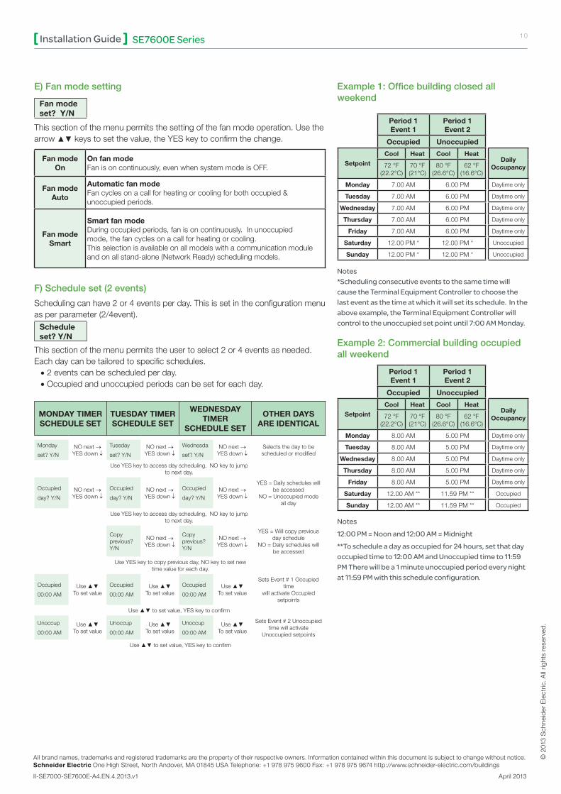
E) Fan mode setting
Fan modeset? Y/N
Thissectionofthemenupermitsthesettingofthefanmodeoperation.Usethearrow ▲▼keystosetthevalue,theYESkeytoconfirmthechange.
Fan modeOn
On fan modeFanisoncontinuously,evenwhensystemmodeisOFF.
Fan modeAuto
Automatic fan modeFancyclesonacallforheatingorcoolingforbothoccupied&unoccupiedperiods.
Fan modeSmart
Smart fan modeDuringoccupiedperiods,fanisoncontinuously.Inunoccupiedmode,thefancyclesonacallforheatingorcooling.Thisselectionisavailableonallmodelswithacommunicationmoduleandonallstand-alone(NetworkReady) schedulingmodels.
F) Schedule set (2 events)
Schedulingcanhave2or4eventsperday.Thisissetintheconfigurationmenuasperparameter(2/4event).
Scheduleset? Y/N
Thissectionofthemenupermitstheusertoselect2or4eventsasneeded.Eachdaycanbetailoredtospecificschedules.•2eventscanbescheduledperday.•Occupiedandunoccupiedperiodscanbesetforeachday.
MONDAY TIMER SCHEDULE SET
TUESDAY TIMER SCHEDULE SET
WEDNESDAY TIMER
SCHEDULE SET
OTHER DAYS ARE IDENTICAL
Monday
set?Y/NNOnext→YESdown↓
Tuesday
set?Y/NNOnext→YESdown↓
Wednesda
set?Y/NNOnext→YESdown↓
Selectsthedaytobescheduledormodified
UseYESkeytoaccessdayscheduling,NOkeytojumptonextday.
Occupied
day?Y/NNOnext→YESdown↓
Occupied
day?Y/NNOnext→YESdown↓
Occupied
day?Y/NNOnext→YESdown↓
YES=Dailyscheduleswillbeaccessed
NO=Unoccupiedmodeallday
UseYESkeytoaccessdayscheduling,NOkeytojumptonextday.
Copyprevious?Y/N
NOnext→YESdown↓
Copyprevious?Y/N
NOnext→YESdown↓
YES=Willcopypreviousdayschedule
NO=Dailyscheduleswillbeaccessed
UseYESkeytocopypreviousday,NOkeytosetnewtimevalueforeachday.
Occupied
00:00AMUse▲▼Tosetvalue
Occupied
00:00AMUse▲▼Tosetvalue
Occupied
00:00AMUse▲▼Tosetvalue
SetsEvent#1Occupiedtime
willactivateOccupiedsetpoints
Use▲▼tosetvalue,YESkeytoconfirm
Unoccup
00:00AMUse▲▼Tosetvalue
Unoccup
00:00AMUse▲▼Tosetvalue
Unoccup
00:00AMUse▲▼Tosetvalue
SetsEvent#2Unoccupiedtimewillactivate
Unoccupiedsetpoints
Use▲▼tosetvalue,YESkeytoconfirm
Example 1: Office building closed all weekend
Period 1 Event 1
Period 1 Event 2
Occupied Unoccupied
Setpoint
Cool Heat Cool HeatDaily
Occupancy72°F(22.2°C)
70°F(21°C)
80°F(26.6°C)
62°F(16.6°C)
Monday 7.00AM 6.00PM Daytimeonly
Tuesday 7.00AM 6.00PM Daytimeonly
Wednesday 7.00AM 6.00PM Daytimeonly
Thursday 7.00AM 6.00PM Daytimeonly
Friday 7.00AM 6.00PM Daytimeonly
Saturday 12.00PM* 12.00PM* Unoccupied
Sunday 12.00PM* 12.00PM* Unoccupied
Notes*Scheduling consecutive events to the same time will cause the Terminal Equipment Controller to choose the last event as the time at which it will set its schedule. In the above example, the Terminal Equipment Controller will control to the unoccupied set point until 7:00 AM Monday.
Example 2: Commercial building occupied all weekend
Period 1 Event 1
Period 1 Event 2
Occupied Unoccupied
Setpoint
Cool Heat Cool HeatDaily
Occupancy72°F(22.2°C)
70°F(21°C)
80°F(26.6°C)
62°F(16.6°C)
Monday 8.00AM 5.00PM Daytimeonly
Tuesday 8.00AM 5.00PM Daytimeonly
Wednesday 8.00AM 5.00PM Daytimeonly
Thursday 8.00AM 5.00PM Daytimeonly
Friday 8.00AM 5.00PM Daytimeonly
Saturday 12.00AM** 11.59PM** Occupied
Sunday 12.00AM** 11.59PM** Occupied
Notes12:00 PM = Noon and 12:00 AM = Midnight**To schedule a day as occupied for 24 hours, set that day occupied time to 12:00 AM and Unoccupied time to 11:59 PM There will be a 1 minute unoccupied period every night at 11:59 PM with this schedule configuration.

© 2
013
Sch
neid
er E
lect
ric. A
ll rig
hts
rese
rved
.
11SE7600E SeriesInstallation Guide
All brand names, trademarks and registered trademarks are the property of their respective owners. Information contained within this document is subject to change without notice.Schneider Electric One High Street, North Andover, MA 01845 USA Telephone: +1 978 975 9600 Fax: +1 978 975 9674 http://www.schneider-electric.com/buildings
II-SE7000-SE7600E-A4.EN.4.2013.v1 April 2013
G) Schedule set (4 events)
Scheduleset? Y/N
Thissectionofthemenupermitstheusertoselect2or4eventsasneeded.Eachdaycanbetailoredtospecificschedules.•4eventscanbescheduledperday.•OccupiedandUnoccupiedperiodscanbesetforeachday.•Schedulingthe3rd&4theventstothesametimewillcancelthelastperiod.
MONDAY TIMER SCHEDULE SET
TUESDAY TIMER SCHEDULE SET
WEDNESDAY TIMER
SCHEDULE SET
OTHER DAYS ARE IDENTICAL
Monday
set?Y/NNOnext→YESdown↓
Tuesday
set?Y/NNOnext→YESdown↓
Wednesda
set?Y/NNOnext→YESdown↓
Selectsthedaytobescheduledormodified
UseYESkeytoaccessdayscheduling,NOkeytojumptonextday.
Occupied
day?Y/NNOnext→YESdown↓
Occupied
day?Y/NNOnext→YESdown↓
Occupied
day?Y/NNOnext→YESdown↓
YES=Dailyscheduleswillbeaccessed
NO=Unoccupiedmodeallday
UseYESkeytoaccessdayscheduling,NOkeytojumptonextday.
Copyprevious?Y/N
NOnext→YESdown↓
Copyprevious?Y/N
NOnext→YESdown↓
YES=Willcopypreviousdayschedule
NO=Dailyscheduleswillbeaccessed
UseYESkeytocopypreviousday,NOkeytosetnewtimevalueforeachday.
Occupied
00:00AMUse▲▼Tosetvalue
Occupied
00:00AMUse▲▼Tosetvalue
Occupied
00:00AMUse▲▼Tosetvalue
SetsEvent#1OccupiedtimewillactivateOccupiedsetpoints
Use▲▼tosetvalue,YESkeytoconfirm
Unoccup
00:00AMUse▲▼Tosetvalue
Unoccup
00:00AMUse▲▼Tosetvalue
Unoccup
00:00AMUse▲▼Tosetvalue
SetsEvent#2UnoccupiedtimewillactivateUnoccupied
setpoints
Use▲▼tosetvalue,YESkeytoconfirm
Occupie2
00:00AMUse▲▼Tosetvalue
Occupie2
00:00AMUse▲▼Tosetvalue
Occupie2
00:00AMUse▲▼Tosetvalue
SetsEvent#3OccupiedtimewillactivateOccupiedsetpoints
Use▲▼tosetvalue,YESkeytoconfirm
Unoccup2
00:00AMUse▲▼Tosetvalue
Unoccup2
00:00AMUse▲▼Tosetvalue
Unoccup2
00:00AMUse▲▼Tosetvalue
SetsEvent#4UnoccupiedtimewillactivateUnoccupied
setpoints
Use▲▼tosetvalue,YESkeytoconfirm
Example 1: Four event retail establishment schedule
Period 1 Event 1
Period 1 Event 2
Period 2 Event 3
Period 2 Event 4
Occupied Unoccupied Occupied Unoccupied
Setpoint
Cool Heat Cool Heat Cool Heat Cool HeatDaily
Occupancy72°F(22.2°C)
70°F(21°C)
80°F(26.6°C)
62°F(16.6°C)
72°F(22.2°C)
70°F(21°C)
80°F(26.6°C)
62°F(16.6°C)
Monday 7.00AM 5.00PM 12.00PM* 12.00PM* Daytimeonly
Tuesday 7.00AM 5.00PM 12.00PM* 12.00PM* Daytimeonly
Wednesday 7.00AM 5.00PM 12.00PM* 12.00PM* Daytimeonly
Thursday 7.00AM 5.00PM 7.00PM 10.30PM Day/Eveonly
Friday 7.00AM 5.00PM 7.00PM 10.30PM Day/Eveonly
Saturday 12.00PM* 12.00PM* 12.00PM* 12.00PM* Unoccupied
Sunday 12.00PM* 12.00PM* 12.00PM* 12.00PM* Unoccupied
Notes* Scheduling events to the same time will cancel the last period and leave the Terminal Equip-ment Controller in unoccupied mode

All brand names, trademarks and registered trademarks are the property of their respective owners. Information contained within this document is subject to change without notice.Schneider Electric One High Street, North Andover, MA 01845 USA Telephone: +1 978 975 9600 Fax: +1 978 975 9674 http://www.schneider-electric.com/buildings
II-SE7000-SE7600E-A4.EN.4.2013.v1 April 2013
© 2
013
Sch
neid
er E
lect
ric. A
ll rig
hts
rese
rved
.
SE7600E SeriesInstallation Guide 12
Example 2: Four event residential schedule
Period 1 Event 1
Period 1 Event 2
Period 2 Event 3
Period 2 Event 4
Occupied Unoccupied Occupied Unoccupied
Setpoint
Cool Heat Cool Heat Cool Heat Cool HeatDaily
Occupancy72°F(22.2°C)
70°F(21°C)
80°F(26.6°C)
62°F(16.6°C)
72°F(22.2°C)
70°F(21°C)
80°F(26.6°C)
62°F(16.6°C)
Monday 6.00AM 8.00AM 4.00PM 10.00PM Day/Eveonly
Tuesday 6.00AM 8.00AM 4.00PM 10.00PM Day/Eveonly
Wednesday 6.00AM 8.00AM 4.00PM 10.00PM Day/Eveonly
Thursday 6.00AM 8.00AM 4.00PM 10.00PM Day/Eveonly
Friday 6.00AM 8.00AM 4.00PM 11.30PM Day/Eveonly
Saturday 8.00AM* 8.00AM* 8.00AM* 11.59PM* Daytimeonly
Sunday 12.00AM* 12.00AM* 12.00AM* 11.59PM* Allday
Notes*Scheduling consecutive events to the same time will cause the Terminal Equipment Controller to choose the last event as the time at which it will set its schedule. In the above example for Saturday, the Terminal Equipment Controller will control to the oc-cupied set point from 8:00 AM until 11:59 PM. Since it is desired to be in occupied mode throughout the night, then it is necessary to schedule the first event on Sunday at 12:00 AM. The Terminal Equipment Controller will force a one minute unoccupied period for a one minute period (between 11:59 PM and 12:00 AM on Saturday).
H) Clock / Day Settings
Clockset? Y/N
Thissectionofthemenupermitstheusertosetthetimeandday.
TIME SETTING
DAYSETTING
TIME FORMAT SETTING
Time
set?Y/N
0:00
NOnext→YESdown↓
Day
set?Y/NNOnext→YESdown↓
12/24hrs
set?Y/NNO=ExitYESdown↓
Time
00:00Use▲▼Tosetvalue
Day
MondayUse▲▼Tosetvalue
12/24hrs
12hrsUse▲▼Tosetvalue
J) Schedule Hold
Schedulehold? Y/N
•Thismenuappearsonlyonstand-alone(NetworkReady)TerminalEquipmentController,i.e.,withoutaBACnet®Echelon®module.
•Thissectionofthemenupermitstheusertosetapermanentschedulehold,whichbypassestheinternalTerminalEquipmentControllerscheduling.
•Thepermanentscheduleholdfunctionistypicallyusedfornon-scheduledeventsthatextendforvariousperiodsoftime.
•Enablingapermanentoccupiedorpermanentunoccupiedscheduleholdwillcancelanyactiveoverride.
•Theuseoftemporarysetpointsduringpermanentholdispermitted.ThedurationofthetemporarysetpointisassetpertheTOccTimeparameter.Ex.3hours.
•Usethearrow▲▼keystosetthevalue,theYESkeytoconfirmthechange.
Scheduleocc hold
Hold permanent occupied ForcestheTerminalEquipmentControllerintoapermanentoccupiedmodeusingtheoccupiedsetpoints.Alltimedschedulingfunctionsareby-passed.
ThePERMANENTOCCUPIED statuswillappearintheautomaticstatusscroll.Toresumetoregularscheduling,scrolltotheScheduleHoldmenuandselecttheScheduleresumeoption.
Scheduleuno hold
Hold permanent unoccupied ForcestheTerminalEquipmentControllerintoapermanentunoccupiedmodeusingtheunoccupiedsetpoints.Alltimedschedulingfunctionsareby-passed.
ThePERMANENTUNOCCUPIEDstatuswillappearintheautomaticstatusscroll.Toresumetoregularscheduling,scrolltotheScheduleHoldmenuandselecttheScheduleresumeoption.
Scheduleresume
Resume regular scheduling Cancelsthepermanentholdand re-enablestheregularschedulingassetperinternalscheduleorasperremoteNSB,viaoneoftheDI’sconfiguredasremoteNSB.
Thisactioncanalsobeaccomp-lishedbyusingtheResumemenu.
Anytemporarysetpointsthatareactivewillbeleftactiveforthedurationoftheperiod,assetpertheTOccTimeparameter.
Schedule Hold and Resume Functions

© 2
013
Sch
neid
er E
lect
ric. A
ll rig
hts
rese
rved
.
13SE7600E SeriesInstallation Guide
All brand names, trademarks and registered trademarks are the property of their respective owners. Information contained within this document is subject to change without notice.Schneider Electric One High Street, North Andover, MA 01845 USA Telephone: +1 978 975 9600 Fax: +1 978 975 9674 http://www.schneider-electric.com/buildings
II-SE7000-SE7600E-A4.EN.4.2013.v1 April 2013
INSTALLER CONFIGURATION PARAMETER MENU ConfigurationcanbeperformedthroughthenetworkorlocallyattheTerminalEquipmentController.
Enter configurationPressandholdthemiddlekey(MENU)foreightseconds.
PasswordIfapasswordlockoutisactive,“Password”isprompted.Enterapasswordvalueusingtheup/downarrowkeysandthenpressthemiddlekeyagaintogainaccesstoallconfigurationpropertiesoftheTer-minalEquipmentController.Enteringanincorrectpasswordwillpreventlocalaccesstotheconfigurationmenu.
Scroll parametersPresstheNOkeyrepetitivelytoscrollbetweenalltheavailableparameters.
Adjust parameterWhenthedesiredparameterisdisplayed,presstheYESkeytoselectit,thenusetheup/downarrowkeystoadjustittothedesiredvalue.Save new valueToacknowledgeandsavethenewvalue,pressYESkeyagain.Thenextparameterwillbedisplayed.
Configuration interface
TheYESkeyisusedtoconfirmaselection,tomoveontothenextmenuitemandtomanuallyscrollthroughthedisplayedinformation.
TheNOkeyisusedwhenyoudonotdesireaparameterchange,andtoadvancetothenextmenuitem.Mayalsobeusedtotogglebetweenheatingandcoolingsetpoints.
TheMENUkeyisusedtoaccesstheMainUserMenuortoexitthemenu.
TheDOWN ARROWkeyisusedtodecreaseatemperaturesetpointandtoadjustthedesiredvalueswhenconfiguringtheTerminalEquipmentController.
TheUP ARROWkeyisusedtoincreaseatemperaturesetpointandtoadjustthedesiredvalueswhenconfiguringtheTerminalEquipmentController.

All brand names, trademarks and registered trademarks are the property of their respective owners. Information contained within this document is subject to change without notice.Schneider Electric One High Street, North Andover, MA 01845 USA Telephone: +1 978 975 9600 Fax: +1 978 975 9674 http://www.schneider-electric.com/buildings
II-SE7000-SE7600E-A4.EN.4.2013.v1 April 2013
© 2
013
Sch
neid
er E
lect
ric. A
ll rig
hts
rese
rved
.
SE7600E SeriesInstallation Guide 14
CONFIGURATION PARAMETERSDefaultValue SignificantAdjustments
PswrdSetConfigurationparametersmenuaccesspasswordDefault:0Nopasswordprompted
Thisparametersetsapasswordaccesstopreventunauthorizedaccesstotheconfigurationmenuparameters.Adefaultvalueof“0”willnotpromptapasswordorlocktheaccesstotheconfigurationmenu.
Rangeis:0to1000
Com AddrTerminalEquipmentControllernetworkingaddressDefault:254Rangeis:0to254
Conditional parameter to BACnet® MS-TP models SE76xxX5x45B
Conditional parameter to Wireless models SE76xxX5x45W
ThisparameterwillonlyappearwhenaBACnet®orwirelessnetworkadapterispresent.IftheTerminalEquipmentControllerisinstalledasastand-alone(Net-workReady)unitorwithanEchelon®adapter,thisparameterwillnotbeusedordisplayed
ForBACnet®MS-TPmodels,thevalidrangeisfrom1to127.Defaultvalueof254disablesBACnet®communicationfortheTerminalEquipmentController.Forwirelessmodels,thevalidrangeis0to254withamaximumof30TerminalEquipmentControllersperVWG
PAN IDPersonalAreaNetworkIdentificationDefault:0Rangeis:0to1045
Conditional parameter to Wireless models SE76xxX5x45W
Thisparameterwillonlyappearwhenawirelessnetworkadapterispresent.IftheTerminalEquipmentControllerisinstalledasastand-alone(NetworkReady)unitorwithaBACnet®orEchelon®adapter,thisparameterwillnotbeusedordisplayed.
Thisparameter(PersonalAreaNetworkIdentification)isusedtolinkspecificTerminalEquipmentControllerstoasinglespecificSchneiderElectricwirelessgateway(VWG).ForeveryTerminalEquipmentControllerreportingtoagateway(maximumof30TerminalEquipmentControllerspergateway),besureyousettheSAMEPANIDvaluebothonthegatewayandtheTerminalEquipmentController(s).
Thedefaultvalueof0isNOTavalidPANID.
ChannelChannelselectionDefault:10Rangeis:10to26
Conditional parameter to Wireless models SE76xxX5x45W
Thisparameterwillonlyappearwhenawirelessnetworkadapterispresent.IftheTerminalEquipmentControllerisinstalledasastand-alone(NetworkReady)unitorwithaBACnet®orEchelon®adapter,thisparameterwillnotbeusedordisplayed.
Thisparameter(Channel)isusedtolinkspecificTerminalEquipmentTerminalEquipmentControllerstospecificSchneiderElectricwirelessgateway(s)(VWG).ForeveryTerminalEquipmentTerminalEquipmentControllerreportingtoagateway(maximumof30TerminalEquipmentControllerspergateway),besureyousettheSAMEchannelvaluebothonthegatewayandtheTerminalEquipmentController(s).
Schneider Electric recommends using only channels 15 and 25.
Thedefaultvalueof10isNOTavalidchannel.Thevalidrangeofavailablechannelsisfrom11to26

© 2
013
Sch
neid
er E
lect
ric. A
ll rig
hts
rese
rved
.
15SE7600E SeriesInstallation Guide
All brand names, trademarks and registered trademarks are the property of their respective owners. Information contained within this document is subject to change without notice.Schneider Electric One High Street, North Andover, MA 01845 USA Telephone: +1 978 975 9600 Fax: +1 978 975 9674 http://www.schneider-electric.com/buildings
II-SE7000-SE7600E-A4.EN.4.2013.v1 April 2013
DefaultValue SignificantAdjustments
AI1Analoginputno.1configurationDefaultvalue=None
None,Nofunctionwillbeassociatedwiththeinput
CO2,the0-10VDCinputvalueisusedasa0-2000ppmCO2level:
0VDC=0ppm
10VDC=2000ppm
FA RangeFArangeupperlimitvalue
Defaultvalue=0CFM
SetstheupperlimitoftheCFMrange.Thisparametershouldbesetbasedontherooftopunitsize.Ifsetto0CFM,thefreshairdampercontrolwillbebasedontheMin/MaxCO2andMin/MaxPosvalues.SeeDamperPositionsectionformoredetails.
0to20000CFM(0to9438L/s),10or100increments
MenuScroMenuscrollDefault:On-Scrollactive
Removesthescrollingdisplayanddisplaystheroomtemperature/humiditytotheuser.Withthisoptionenabled,nomode,scheduleandoutdoortemperaturestatusisgiven.
•On=Scrollactive•Off=Scrollnotactive
lockout KeypadlockoutlevelsDefaultvalue=0(Nolock)
0=Nolock1=Lowlevel2=Highlevel
USERKEYFUNCTIONS
LEVEL
Resume/
Override
Scheduling
PermanentOccupiedandUnoccupiedSetpoints
Temporarysetpointsusingarrows
Systemmodesetting
Fanmodesetting
Schedulessetting
Clocksetting
Permanenthold
0 Unlocked Unlocked Unlocked Unlocked Unlocked Unlocked Unlocked Unlocked
1 Unlocked Locked Unlocked Locked Locked Locked Unlocked Locked
2 Locked Locked Locked Locked Locked Locked Unlocked Locked
pwr delPower-updelayDefaultvalue=10seconds
OninitialpowerupoftheTerminalEquipmentController(eachtime24Vacpowersupplyisremoved&re-applied)thereisadelaybeforeanyoperationisauthorized(fan,coolingorheating).Thiscanbeusedtosequencestartupmultipleunits/TerminalEquipmentControllerinonelocation.10to120seconds
CONFIGURATION PARAMETERS

All brand names, trademarks and registered trademarks are the property of their respective owners. Information contained within this document is subject to change without notice.Schneider Electric One High Street, North Andover, MA 01845 USA Telephone: +1 978 975 9600 Fax: +1 978 975 9674 http://www.schneider-electric.com/buildings
II-SE7000-SE7600E-A4.EN.4.2013.v1 April 2013
© 2
013
Sch
neid
er E
lect
ric. A
ll rig
hts
rese
rved
.
SE7600E SeriesInstallation Guide 16
CONFIGURATION PARAMETERSDefaultValue SignificantAdjustments
Frost prFrostprotectionenabledDefaultvalue=Off
Off:noroomfrostprotectionOn:roomfrostprotectionenabledinallsystemmodeat:42°F(5.6°C)FrostprotectionisenabledeveninsystemOffmodeOfforOn(OnheatpumpmodelsthesystemmodewillbeforcedtoEMERGENCYmodeiffrostprotectionisactivated.)
Heat max MaximumheatingsetpointlimitDefault:90°F(32°C)
Maximumoccupied&unoccupiedheatingsetpointadjustment.
Heatingsetpointrangeis:40to90°F(4.5to32.0°C)
Cool minMinimumcoolingsetpointlimitDefault:54°F(12°C)
Minimumoccupied&unoccupiedcoolingsetpointadjustment.
Coolingsetpointrangeis:54to100°F(12.0to37.5°C)
PbandProportionalBandsettingDefaultvalue2=2.0°F(0.6°C
AdjuststheproportionalbandusedbytheTerminalEquipmentControllerPIcontrolloop.
Notethatthedefaultvalueof2.0°F(1.1°C)givessatisfactoryoperationinmostnormalinstallationcases.TheuseofaproportionalbanddifferentthanthefactoryoneisnormallywarrantedinapplicationswheretheTerminalEquipmentControllerlocationisproblematicandleadstounwantedcyclingoftheunit.AtypicalexampleisawallmountedunitwheretheTerminalEquipmentControllerisinstalledbetweenthereturnandsupplyairfeedsandisdirectlyinfluencedbythesupplyairstreamoftheunit.
VALUE°F SCALE PBAND
°C SCALEPBAND
2 2 F 1.1 C3 3 F 1.7 C4 4 F 2.2 C5 5 F 2.8 C6 6 F 3.3 C7 7 F 3.9 C8 8 F 4.4 C
AnticycleMinimumOn-OffoperationtimeforstagesDefaultvalue=2minutes
MinimumOn-Offoperationtimeofcooling&heatingstages.
IMPORTANT,anti-shortcyclingcanbesetto0minutesforequipmentthatpossestheirownanticyclingtimer.Donotusethisvalueunlesstheequipmentisequippedwithsuchinternaltimer.Failuretodosocandamagetheequipment.0,1,2,3,4&5minutes
Anti-shortcyclingcanbesetto0minutesforequipmentthatpossestheirownanticyclingtimer.Donotusethatvalueunlesstheequipmentisequippedwithsuchinternaltimer.Failuretodosocandamagetheequipment.
DefaultValue SignificantAdjustments
© 2
013
Sch
neid
er E
lect
ric. A
ll rig
hts
rese
rved
.
17SE7600E SeriesInstallation Guide
All brand names, trademarks and registered trademarks are the property of their respective owners. Information contained within this document is subject to change without notice.Schneider Electric One High Street, North Andover, MA 01845 USA Telephone: +1 978 975 9600 Fax: +1 978 975 9674 http://www.schneider-electric.com/buildings
II-SE7000-SE7600E-A4.EN.4.2013.v1 April 2013
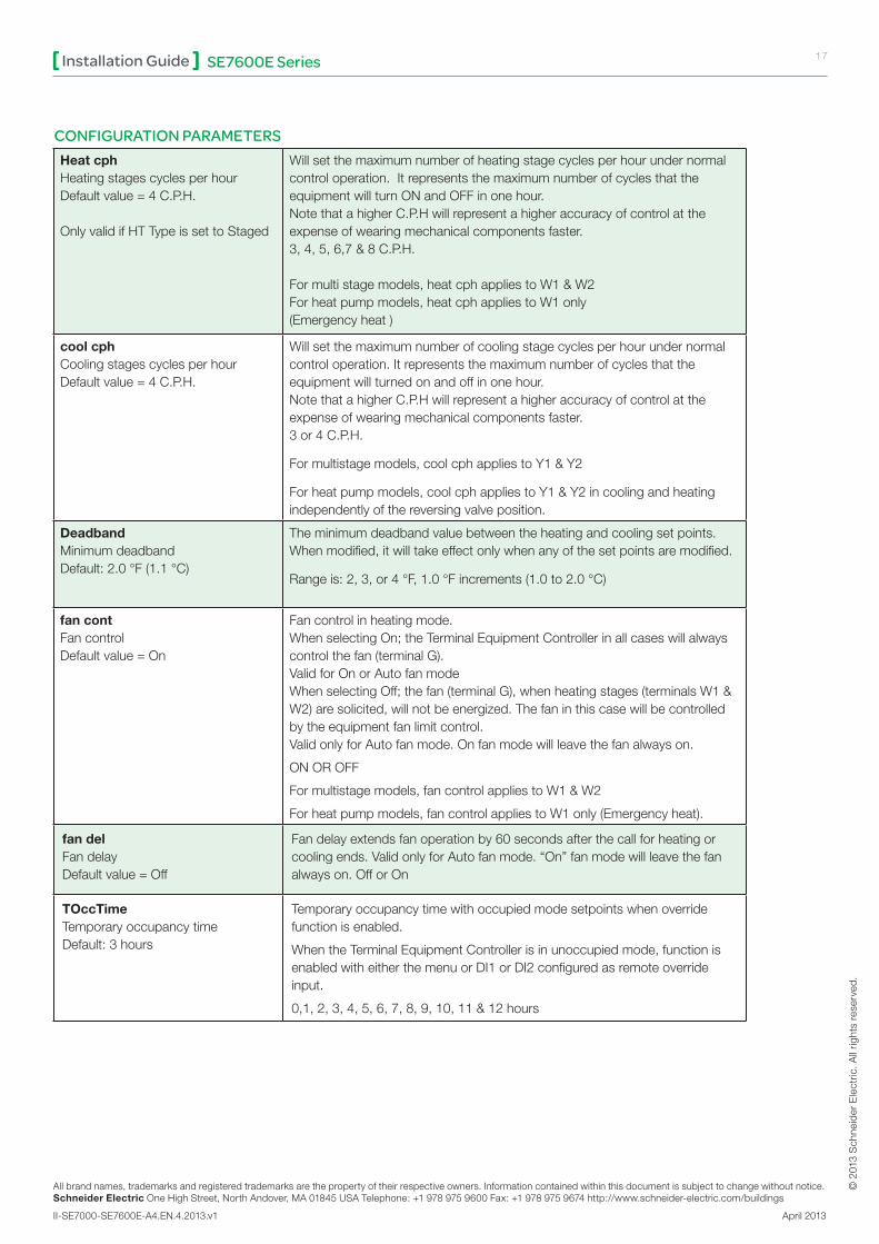
Heat cphHeatingstagescyclesperhourDefaultvalue=4C.P.H.
OnlyvalidifHTTypeissettoStaged
Willsetthemaximumnumberofheatingstagecyclesperhourundernormalcontroloperation.ItrepresentsthemaximumnumberofcyclesthattheequipmentwillturnONandOFFinonehour.NotethatahigherC.P.Hwillrepresentahigheraccuracyofcontrolattheexpenseofwearingmechanicalcomponentsfaster.3,4,5,6,7&8C.P.H.
Formultistagemodels,heatcphappliestoW1&W2Forheatpumpmodels,heatcphappliestoW1only(Emergencyheat)
cool cphCoolingstagescyclesperhourDefaultvalue=4C.P.H.
Willsetthemaximumnumberofcoolingstagecyclesperhourundernormalcontroloperation.Itrepresentsthemaximumnumberofcyclesthattheequipmentwillturnedonandoffinonehour.NotethatahigherC.P.Hwillrepresentahigheraccuracyofcontrolattheexpenseofwearingmechanicalcomponentsfaster.3or4C.P.H.
Formultistagemodels,coolcphappliestoY1&Y2
Forheatpumpmodels,coolcphappliestoY1&Y2incoolingandheatingindependentlyofthereversingvalveposition.
DeadbandMinimumdeadbandDefault:2.0°F(1.1°C)
Theminimumdeadbandvaluebetweentheheatingandcoolingsetpoints.Whenmodified,itwilltakeeffectonlywhenanyofthesetpointsaremodified.
Rangeis:2,3,or4°F,1.0°Fincrements(1.0to2.0°C)
fan contFancontrolDefaultvalue=On
Fancontrolinheatingmode.WhenselectingOn;theTerminalEquipmentControllerinallcaseswillalwayscontrolthefan(terminalG).ValidforOnorAutofanmodeWhenselectingOff;thefan(terminalG),whenheatingstages(terminalsW1&W2)aresolicited,willnotbeenergized.Thefaninthiscasewillbecontrolledbytheequipmentfanlimitcontrol.ValidonlyforAutofanmode.Onfanmodewillleavethefanalwayson.
ONOROFF
Formultistagemodels,fancontrolappliestoW1&W2
Forheatpumpmodels,fancontrolappliestoW1only(Emergencyheat).
fan delFandelayDefaultvalue=Off
Fandelayextendsfanoperationby60secondsafterthecallforheatingorcoolingends.ValidonlyforAutofanmode.“On”fanmodewillleavethefanalwayson.OfforOn
TOccTime TemporaryoccupancytimeDefault:3hours
Temporaryoccupancytimewithoccupiedmodesetpointswhenoverridefunctionisenabled.
WhentheTerminalEquipmentControllerisinunoccupiedmode,functionisenabledwitheitherthemenuorDI1orDI2configuredasremoteoverrideinput.
0,1,2,3,4,5,6,7,8,9,10,11&12hours
CONFIGURATION PARAMETERS

All brand names, trademarks and registered trademarks are the property of their respective owners. Information contained within this document is subject to change without notice.Schneider Electric One High Street, North Andover, MA 01845 USA Telephone: +1 978 975 9600 Fax: +1 978 975 9674 http://www.schneider-electric.com/buildings
II-SE7000-SE7600E-A4.EN.4.2013.v1 April 2013
© 2
013
Sch
neid
er E
lect
ric. A
ll rig
hts
rese
rved
.
SE7600E SeriesInstallation Guide 18
CONFIGURATION PARAMETERS
DefaultValue SignificantAdjustments
Cal RS RoomairtemperaturesensorcalibrationDefault:0.0°For°C
Offsetthatcanbeadded/subtractedtotheactualdisplayedroomtemperature.
Rangeis:±5.0°F(±2.5°C)
Cal OSOutsideairtemperaturesensorcalibrationDefaultvalue=0.0°For°C
Offsetthatcanbeadded/subtractedtoactualdisplayedoutsideairtemperature±5.0°F(±2.5°C)
H stageNumberofheatingstages.Defaultvalue=2stages
Willreverttheoperationof2stagesthermostattosinglestageoperationortomodulating0to10Vdcheatingoutput:
0=0-10Vdcanalogheatingoutput(AO)1=1heatingstage(W1)2=2heatingstages(W1&W2)
C stageNumberofcoolingstagesDefaultvalue=2stages
Willreverttheoperationof2stageTerminalEquipmentControllertosinglestageoperationonlywhenthesecondcoolingstepisnotneeded.1or2stages
H lockOutsideairtemperatureheatinglockoutDefaultvalue=120°F(49°C)
Disablesheatingstageoperationbasedonoutdoorairtemperature.FunctionwillonlybeenabledifOS(outsideairtemperaturesensor)isconnected.
From-15°Fupto120°F(-26°Cupto49°C)
C lockOutsideairtemperaturemechanicalcoolinglockout.Defaultvalue=-40°F(-40°C)
Disablescoolingstageoperationbasedonoutdoorairtemperature.Oneconomizermodel,freecoolingwillnotbedisabledbythisfunction.FunctionwillonlybeenabledifOS(outsideairtemperaturesensor)isconnected.
From-40°Fupto95°F(-40°Cupto35°C)
Unocc TMUnoccupiedTimervalueDefault=0.5hours
TimedelaybetweenthemomentwheretheTerminalEquipmentControllertogglesfromoccupiedtounoccupiedafterthelastmovementhasbeendetectedbythePIR.
Rangeis:0.5to24.0hoursin0.5hourincrements.
2/4eventNumberofeventsconfigurationDefaultvalue=2events
2events,willsetupschedulingforthefollowing:Event1isforOccupiedsetpointsEvent2isforUnoccupiedsetpoints
4events,willsetupschedulingforthefollowing:Event1isforOccupiedsetpointsEvent2isforUnoccupiedsetpointsEvent3isforOccupiedsetpointsEvent4isforUnoccupiedsetpoints
MS disDisplaymixedairtemperature
Usedasdiagnosticaidtotroubleshootanddiagnoseeconomizeroperation.
© 2
013
Sch
neid
er E
lect
ric. A
ll rig
hts
rese
rved
.
19SE7600E SeriesInstallation Guide
All brand names, trademarks and registered trademarks are the property of their respective owners. Information contained within this document is subject to change without notice.Schneider Electric One High Street, North Andover, MA 01845 USA Telephone: +1 978 975 9600 Fax: +1 978 975 9674 http://www.schneider-electric.com/buildings
II-SE7000-SE7600E-A4.EN.4.2013.v1 April 2013
CONFIGURATION PARAMETERS
DefaultValue SignificantAdjustments
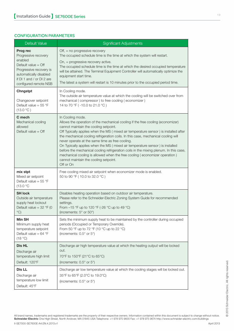
Prog recProgressiverecoveryenabledDefaultvalue=OffProgressiverecoveryisautomaticallydisabledifDI1and/orDI2areconfiguredremoteNSB
Off,=noprogressiverecoveryTheoccupiedscheduletimeisthetimeatwhichthesystemwillrestart.
On,=progressiverecoveryactive.Theoccupiedscheduletimeisthetimeatwhichthedesiredoccupiedtemperaturewillbeattained.TheTerminalEquipmentControllerwillautomaticallyoptimizetheequipmentstarttime.
Thelatestasystemwillrestartis10minutespriortotheoccupiedperiodtime.
Chngstpt
ChangeoversetpointDefaultvalue=55°F(13.0°C)
InCoolingmode.Theoutsideairtemperaturevalueatwhichthecoolingwillbeswitchedoverfrommechanical(compressor)tofreecooling(economizer)14to70°F(-10.0to21.0°C)
C mechMechanicalcoolingallowedDefaultvalue=Off
InCoolingmode.Allowstheoperationofthemechanicalcoolingifthefreecooling(economizer)cannotmaintainthecoolingsetpoint.OffTypicallyapplieswhentheMS(mixedairtemperaturesensor)isinstalledafterthemechanicalcoolingrefrigerationcoils.Inthiscase,mechanicalcoolingwillneveroperateatthesametimeasfreecooling.OnTypicallyapplieswhentheMS(mixedairtemperaturesensor)isinstalledbeforethemechanicalcoolingrefrigerationcoilsinthemixingplenum.Inthiscase,mechanicalcoolingisallowedwhenthefreecooling(economizeroperation)cannotmaintainthecoolingsetpoint.OfforOn
mix stptMixedairsetpointDefaultvalue=55°F(13.0°C
Freecoolingmixedairsetpointwheneconomizermodeisenabled.50to90°F(10.0to32.0°C)
SH lockOutsideairtemperaturesupplyheatlockoutDefaultvalue=32°F(0°C)
Disablesheatingoperationbasedonoutdoorairtemperature.PleaserefertotheSchneider-ElectricZoningSystemGuideforrecommendedsettings.From–15°Fupto120°F(-26°Cupto49°C)(increments:5°or50°)
Min SHMinimumsupplyheattemperaturesetpointDefaultvalue=64°F(18°C)
Setstheminimumsupplyheattobemaintainedbythecontrollerduringoccupiedperiods(OccupiedorTemporaryOverride).From50°Fupto72°F(10°Cupto22°C)(increments:0.5°or5°)
Dis HL
Dischargeairtemperaturehighlimit
Default:120°F
Dischargeairhightemperaturevalueatwhichtheheatingoutputwillbelockedout.
70°Fto150°F(21°Cto65°C)
(increments:0.5°or5°)
Dis LL
Dischargeairtemperaturelowlimit
Default:45°F
Dischargeairlowtemperaturevalueatwhichthecoolingstageswillbelockedout.
35°Fto65°F(2.0°Cto19.0°C)
(increments:0.5°or5°)

All brand names, trademarks and registered trademarks are the property of their respective owners. Information contained within this document is subject to change without notice.Schneider Electric One High Street, North Andover, MA 01845 USA Telephone: +1 978 975 9600 Fax: +1 978 975 9674 http://www.schneider-electric.com/buildings
II-SE7000-SE7600E-A4.EN.4.2013.v1 April 2013
© 2
013
Sch
neid
er E
lect
ric. A
ll rig
hts
rese
rved
.
SE7600E SeriesInstallation Guide 20
CONFIGURATION PARAMETERS
DefaultValue SignificantAdjustments
Min PosMinimumFreshAirDamper/EconomizerPositionDefaultvalue=0%
Minimumfreshairdamperposition.EffectiveonlyinOccupiedmode(FanisON).ThisvalueisalsousedtodeterminethefreshairdamperpositionbasedontheMin/MaxCO2andMin/MaxPosvaluesset.SeeFreshAirDamperPositionsectionformoredetails.
0%to100%,1or10increments
Max PosMaximumFreshAirDamper/EconomizerPositionDefaultvalue=100%
Maximumfreshairdamperposition.EffectiveonlyinOccupiedmode(FanisON).ThisvalueisusedtodeterminethefreshairdamperpositionbasedontheMin/MaxCO2andMin/MaxPosvaluesset.SeeFreshAirDamperPositionsectionformoredetails.
0%to100%,1or10increments
Min FAMinimumFreshAirValueDefaultvalue=0CFM
Minimumfreshairrequired.EffectiveonlyinOccupiedmode(FanisON).ThisvalueisusedtodeterminethefreshairdamperpositionbasedontheMin/MaxCO2andMin/MaxFAvalues(ifFARangeissettootherthan0CFM).SeeFreshAirDamperPositionsectionformoredetails.
0to20000CFM(0to9438L/s)(thevaluesetcannotexceedthevalueofFARangeparameter),10or100increments
Max FAMaximumFreshAirValueDefaultvalue=0CFM
Maximumfreshairallowed.EffectiveonlyinOccupiedmode(FanisON).ThisvalueisusedtodeterminethefreshairdamperpositionbasedontheMin/MaxCO2andMin/MaxFAvaluesset(ifFARangeissettootherthan0CFM).SeeFreshAirDamperPositionsectionformoredetails.
0to20000CFM(0to9438L/s)(thevaluesetcannotexceedthevalueofFARangeparameter),10or100increments
Min CO2MinimumCO2LevelDefaultvalue=800ppm
MinimumCO2Levelrequired.EffectiveonlyinOccupiedmode(FanisON).ThisvalueisusedtodeterminethefreshairdamperpositionbasedontheMin/MaxCO2andMin/MaxPosvaluesset.SeeFreshAirDamperPositionsectionformoredetails.
0to2000ppm,10or100increments
Max CO2MaximumCO2LevelDefaultvalue=1200ppm
MaximumCO2Levelallowed.EffectiveonlyinOccupiedmode(FanisON).ThisvalueisusedtodeterminethefreshairdamperpositionbasedontheMin/MaxCO2andMin/MaxPosvaluesset.SeeFreshAirDamperPositionsectionformoredetails.
0to2000ppm,10or100increments
CO2 LevelDisplayCO2Level,onlyifaCO2transmitterisinstalledatAI1input
Usedasdiagnostic/servicehelptotroubleshootanddiagnoseIAQcontroloperation
© 2
013
Sch
neid
er E
lect
ric. A
ll rig
hts
rese
rved
.
21SE7600E SeriesInstallation Guide
All brand names, trademarks and registered trademarks are the property of their respective owners. Information contained within this document is subject to change without notice.Schneider Electric One High Street, North Andover, MA 01845 USA Telephone: +1 978 975 9600 Fax: +1 978 975 9674 http://www.schneider-electric.com/buildings
II-SE7000-SE7600E-A4.EN.4.2013.v1 April 2013
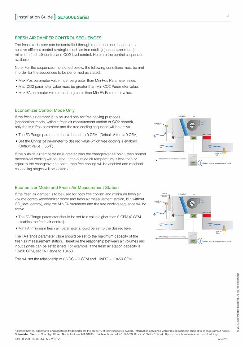
FRESH AIR DAMPER CONTROL SEQUENCES Thefreshairdampercanbecontrolledthroughmorethanonesequencetoachievedifferentcontrolstrategiessuchasfreecooling(economizermode),minimumfreshaircontrolandCO2levelcontrol.Herearethecontrolsequencesavailable:
Note:Forthesequencesmentionedbelow,thefollowingconditionsmustbemetinorderforthesequencestobeperformedasstated:
•MaxPosparametervaluemustbegreaterthanMinPosParametervalue.
•MacCO2parametervaluemustbegreaterthanMinCO2Parametervalue.
•MaxFAparametervaluemustbegreaterthanMinFAParametervalue.
Economizer Control Mode Only
Ifthefreshairdamperistobeusedonlyforfreecoolingpurposes(economizermode,withoutfreshairmeasurementstationorCO2control),onlytheMinPosparameterandthefreecoolingsequencewillbeactive.
•TheFARangeparametershouldbesetto0CFM.(DefaultValue=0CFM)
•SettheChngstptparametertodesiredvaluewhichfreecoolingisenabled.(DefaultValue=55°F)
Iftheoutsideairtemperatureisgreaterthanthechangeoversetpoint,thennormalmechanicalcoolingwillbeused.Iftheoutsideairtemperatureislessthanorequaltothechangeoversetpoint,thenfreecoolingwillbeenabledandmechani-calcoolingstageswillbelockedout.
Economizer Mode and Fresh-Air Measurement Station
Ifthefreshairdamperistobeusedforbothfreecoolingandminimumfreshairvolumecontrol(economizermodeandfreshairmeasurementstation,butwithoutCO2levelcontrol),onlytheMinFAparameterandthefreecoolingsequencewillbeactive.
•TheFARangeparametershouldbesettoavaluehigherthan0CFM(0CFMdisablesthefreshaircontrol).
•MinFA(minimumfreshair)parametershouldbesettothedesiredlevel.
TheFARangeparametervalueshouldbesettothemaximumcapacityofthefreshairmeasurementstation.Thereforetherelationshipbetweenairvolumesandinputsignalscanbeestablished.Forexample,ifthefreshairstationcapacityis10450CFM,setFARangeto10450.
Thiswillsettherelationshipof0VDC=0CFMand10VDC=10450CFM.
ControlBoard
Outside AirSensor
Supply AirSensor
OA
RA
Cooling Coil Fan
Heating Coil
SA
BACnet® open communication protocols
ZigBee® optional communication protocols
ControlBoard
Outside AirSensor
Supply AirSensor
OA
RA
Cooling Coil Fan
Heating Coil
SA
BACnet® open communication protocols
ZigBee® optional communication protocols
Fresh air measurement
station

All brand names, trademarks and registered trademarks are the property of their respective owners. Information contained within this document is subject to change without notice.Schneider Electric One High Street, North Andover, MA 01845 USA Telephone: +1 978 975 9600 Fax: +1 978 975 9674 http://www.schneider-electric.com/buildings
II-SE7000-SE7600E-A4.EN.4.2013.v1 April 2013
© 2
013
Sch
neid
er E
lect
ric. A
ll rig
hts
rese
rved
.
SE7600E SeriesInstallation Guide 22
FRESH AIR DAMPER CONTROL SEQUENCES (CONT.)
Economizer Mode and CO2 Level Control
IfthefreshairdamperistobeusedforbothfreecoolingandCO2levelcontrol(economizermodeandCO2levelcontrol,butwithoutfreshairmeasurementstation),onlytheMinPos,MaxPos,MinCO2andMaxCO2parametersaswellasthefreecoolingsequencewillbeactive.
•TheFARangeparametershouldbesetto0CFM.
•SetAI1parametertoCO2(0VDC=0ppm;10VDC=2000ppm)
•MinPos,MaxPos,MinCO2andMaxCO2parametersshouldbesetaccordingtotherequiredsetting.
Thehighestvaluebetweenfreecoolingdemandoutputandinterpolationoutputforthefreshairsetpointwillbetheoutputtothefreshairdamper.
Economizer Mode, CO2 Level Control and Fresh-Air Measurement Station
IfthefreshairdamperistobeusedforbothfreecoolingandCO2levelcontrolwithafreshairmeasurementstation,onlytheMinFA,MaxFA,MinCO2andMaxCO2parametersaswellasthefreecoolingsequencewillbeactive.
•TheFARangeparametershouldbesettosomethingotherthan0CFM.
•UseanairflowtransmittertoreadfreshairlevelwithAI2input(0-5VDCinput)
•MinFA,MaxFA,MinCO2andMaxCO2parametersshouldbesetaccordingtotherequiredsetting.
ThehighestvaluebetweenfreecoolingdemandoutputandinterpolationoutputforthefreshairsetpointbasedontheCO2levelwillbetheoutputtothefreshairdamper
ControlBoard
Outside AirSensor
Supply AirSensor
OA
RA
Cooling Coil Fan
Heating Coil
SA
BACnet® open communication protocols ZigBee® optional communication protocols
Fresh air measurement
station
CO2Sensor
ControlBoard
Outside AirSensor
Supply AirSensor
OA
RA
Cooling Coil Fan
Heating Coil
SA
ZigBee® optional communication protocolsBACnet® open communication protocols
CO2Sensor

© 2
013
Sch
neid
er E
lect
ric. A
ll rig
hts
rese
rved
.
23SE7600E SeriesInstallation Guide
All brand names, trademarks and registered trademarks are the property of their respective owners. Information contained within this document is subject to change without notice.Schneider Electric One High Street, North Andover, MA 01845 USA Telephone: +1 978 975 9600 Fax: +1 978 975 9674 http://www.schneider-electric.com/buildings
II-SE7000-SE7600E-A4.EN.4.2013.v1 April 2013
SPECIFICATIONS
TerminalEquipmentControllerpowerrequirements:19-30VAC50or60Hz;2VAClass2RCtoRHjumper2.0Amps48VAmax.
Operatingconditions0°Cto50°C(32°Fto122°F)0%to95%R.H.non-condensing
Storageconditions-30°Cto50°C(-22°Fto122°F)0%to95%R.H.non-condensing
Temperaturesensor Local10KNTCthermistor
Temperatesensorresolution ±0.1°C(±0.2°F)
Temperaturecontrolaccuracy ±0.5°C(±0.9°F)@21°C(70°F)typicalcalibrated
Contactoutputrating Relayoutput:30VAC,1Amp.Maximum,3Amp.In-rush.
Occ,Stand-ByandUnocccoolingsetpointrange 12.0to37.5°C(54to100°F)
Occ,Stand-ByandUnoccheatingsetpointrange 4.5°Cto32°C(40°Fto90°F)
Roomandoutdoorairtemperaturedisplayrange -40°Cto50°C(-40°Fto122°F)
Proportionalbandforroomtemp.displayrange: Factorydefault:Cooling&Heating:1.8˚C(3.2˚F)(Adjustable).
CO2andairflowanaloginputs: 0to10VDCinputacrossScom,AI1andAI2.
Analogheat&economizeranalogoutputsrating: 0-10VDCinto2KWresistancemin.
Analogheat&economizeranalogoutputaccuracy: ±3%typical
Wiregauge 18gaugemax.22gaugemin.
Approximateshippingweight 0.75lb(0.34kg)
AgencyApprovalsallmodelsUL:UL873(US)andCSAC22.2No.24(Canada),FileE27734withCCNXAPX(US)andXAPX7(Canada)IndustryCanada:ICES-003(Canada)
AgencyApprovalsallmodels
FCC:ComplianttoCFR47,Part15,SubpartB,ClassA(US)CE:EMCDirective2004/108/EC(EuropeUnion)C-Tick:AS/NZSCISPR22Compliant(Australia/NewZealand)SupplierCodeNumberN10696
AgencyApprovalsWirelessmodels FCC:Compliantto:Part15,SubpartB,Class(US)
THISDEVICECOMPLIESWITHPART15OFTHEFCCRULES.OPERATIONISSUBJECTTOTHEFOLLOWINGTWOCONDITIONS:(1)THISDEVICEMAYNOTCAUSEHARMFULINTERFERENCE,AND(2)THISDEVICEMUSTACCEPTANYINTERFERENCERECEIVED,INCLUDINGINTERFERENCETHATMAYCAUSEUNDESIREDOPERATION.
Pleasecheckwithyourlocalgovernmentforinstructionondisposalofthisproduct.

All brand names, trademarks and registered trademarks are the property of their respective owners. Information contained within this document is subject to change without notice.Schneider Electric One High Street, North Andover, MA 01845 USA Telephone: +1 978 975 9600 Fax: +1 978 975 9674 http://www.schneider-electric.com/buildings
II-SE7000-SE7600E-A4.EN.4.2013.v1 April 2013
© 2
013
Sch
neid
er E
lect
ric. A
ll rig
hts
rese
rved
.
SE7600E SeriesInstallation Guide 24
DIMENSIONAL DRAWING